US1281663A - Combined hand-rail and water-gage. - Google Patents
Combined hand-rail and water-gage. Download PDFInfo
- Publication number
- US1281663A US1281663A US23583818A US23583818A US1281663A US 1281663 A US1281663 A US 1281663A US 23583818 A US23583818 A US 23583818A US 23583818 A US23583818 A US 23583818A US 1281663 A US1281663 A US 1281663A
- Authority
- US
- United States
- Prior art keywords
- rail
- gage
- water
- tank
- locomotive
- Prior art date
- Legal status (The legal status is an assumption and is not a legal conclusion. Google has not performed a legal analysis and makes no representation as to the accuracy of the status listed.)
- Expired - Lifetime
Links
Images
Classifications
-
- F—MECHANICAL ENGINEERING; LIGHTING; HEATING; WEAPONS; BLASTING
- F22—STEAM GENERATION
- F22B—METHODS OF STEAM GENERATION; STEAM BOILERS
- F22B37/00—Component parts or details of steam boilers
- F22B37/78—Adaptations or mounting of level indicators
Definitions
- 1 provide a substantially vertical metal gage tube, 1, which is connected. at or near its lower end, by a tubular coupling, 2, with the water tank. 3, of a locomotive tender.
- the upper end of the gage tube is connected to the tank by a coupling, 2, which m y either be tubular or solid, and in the latter case, an opening should be formed in it to establish communication between the interior of the gage tube and the atmosphere.
- the gage tube, 1, is.
Landscapes
- Engineering & Computer Science (AREA)
- Physics & Mathematics (AREA)
- Thermal Sciences (AREA)
- Mechanical Engineering (AREA)
- General Engineering & Computer Science (AREA)
- Emergency Lowering Means (AREA)
Description
C. 0. ROGERS.
COMBINED HAND RAIL AND WATER GAGE.
APPLICATION FILED MAYZI, 191s.
Patented Oct. 15, 1915 WITNESSES CAMP-BELL o. noenns,
(DIE TROY, IZE'W YGIi-K,
'GQHIEBIIFED HANE-RAEL AND WATERkGAGE.
mam
Specification of Letters Patent.
Patented @cm 215,
application filed may 21, 1918. Serial No. 235,838.
- particularly to appliances if such type designed for application to the Water tank of a locomotive engine, and its object is to effect, by a simple and inexpensive construction, the utilization of an ordinarily existing member of a locomotive tender, for the performance of this function, in addition to its us al and normal one.
'1 1e improvement claimed is hereinafter set forth.
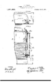
in the accompanyin; is a vertical longitmlina forward portio 0: the winter, and; lig. 2, a plan or top view of the same.
In the practice of my invention, referring descriptively to the specific embodiment thereof which is herein exemplified, 1 provide a substantially vertical metal gage tube, 1, which is connected. at or near its lower end, by a tubular coupling, 2, with the water tank. 3, of a locomotive tender. The upper end of the gage tube is connected to the tank by a coupling, 2, which m y either be tubular or solid, and in the latter case, an opening should be formed in it to establish communication between the interior of the gage tube and the atmosphere. The gage tube, 1, is. preferably, as shown, located suiiiciently far from the tank to enable it to be grasped by an operator in getting on or oil the locomotive, and in the poshim'i occupier by the ordinary hand rail which is app I to facilitate ingress and e s to and from the locomotive cab an l 1 located, perfor the it rail, in addition to that plurality of small. perforations Figure l hrough the kili of a locomotive or vents, 1*, 1
is formed in the gage tu e, at ed 0. determined inteiuals i .i\,.ngtl1,' intervals may be less greater,
to the degree a; acc-i indication c t lo ot a gage tube. A
vent liability tofreezing, a small drain hole,
1", is formed at the bottom of the gage tube, to allow all water to escape therefrom when not under observation as an indicator.
The advantage of my invention as compared with indicators of the type in which a float or a glass sight tube is applied, will be obvious to those familiar with the conditions of locomotive operation, and as the appliance can be substituted for the ordinary tender hand rail, its application is easy and inexpensive.
I claim as my invention and desire to secure by Letters Patent:
1. The combination, with a locomotive tender tank, of a vertical tubular metal. band rail supported from the wall of the tank its top and bottom, the support at the bottom of the rail having a passage there-- through putting the tank water space in communication with the inside of the rail, a valve in said passage to control such communication, and means operable at the top of the tank to actuate said valve, said rail having a plurality of vents di posed at regular intervals throughout its length.
2. The combination, with a locomotive tender tank. of a tubular hand rail connected thereto, a ti ular connection from the inside of the tank to the inside of the rail near the bottom of tee latter, a valve in said connection, a rod to actuate said valve extending above the top of the tank, and a handle on the upper end of said rod, said rail having an air vent at its top, a drain vent at its bottom, and a plurality of vents disposed at intervals throughout its length.
J. SNo-WDEN BELL, EDWARD A. WRIGHT.
Priority Applications (1)
| Application Number | Priority Date | Filing Date | Title |
|---|---|---|---|
| US23583818A US1281663A (en) | 1918-05-21 | 1918-05-21 | Combined hand-rail and water-gage. |
Applications Claiming Priority (1)
| Application Number | Priority Date | Filing Date | Title |
|---|---|---|---|
| US23583818A US1281663A (en) | 1918-05-21 | 1918-05-21 | Combined hand-rail and water-gage. |
Publications (1)
| Publication Number | Publication Date |
|---|---|
| US1281663A true US1281663A (en) | 1918-10-15 |
Family
ID=3349253
Family Applications (1)
| Application Number | Title | Priority Date | Filing Date |
|---|---|---|---|
| US23583818A Expired - Lifetime US1281663A (en) | 1918-05-21 | 1918-05-21 | Combined hand-rail and water-gage. |
Country Status (1)
| Country | Link |
|---|---|
| US (1) | US1281663A (en) |
-
1918
- 1918-05-21 US US23583818A patent/US1281663A/en not_active Expired - Lifetime
Similar Documents
| Publication | Publication Date | Title |
|---|---|---|
| US1396606A (en) | Funnel | |
| US1281663A (en) | Combined hand-rail and water-gage. | |
| US1623374A (en) | Float valve | |
| US1859479A (en) | Sanitary vent for gravity milk-tanks | |
| US2771944A (en) | Emergency fuel reservoir and gauge | |
| US2399167A (en) | Tank filler | |
| US1423411A (en) | Liquid-level indicator | |
| US2895447A (en) | Liquid level indicators | |
| US914936A (en) | Automatic cut-off for cisterns. | |
| US1336280A (en) | Automatic air-vent | |
| US1482144A (en) | Garbage-disposal device | |
| US1443402A (en) | Signal for refrigerator pans | |
| US1546013A (en) | Fuel-reserve-supply device | |
| US1225178A (en) | Fuel-tank gage. | |
| US2198291A (en) | Automatic air relief valve | |
| US871427A (en) | Controlling device for deep-seal siphons. | |
| US484619A (en) | Henry e | |
| US770548A (en) | Tank-car indicator | |
| US1442502A (en) | Reserve oil tank for automobiles | |
| US1408022A (en) | Radiator alarm | |
| US1223190A (en) | Attachment for vapor-heating systems. | |
| US757947A (en) | Gage for sand-boxes. | |
| US1390415A (en) | Oil-gage | |
| US550023A (en) | Apparatus for cleaning reservoirs | |
| US125487A (en) | Improvement in steam-traps |