US1277458A - Window-scaffold. - Google Patents
Window-scaffold. Download PDFInfo
- Publication number
- US1277458A US1277458A US5508415A US5508415A US1277458A US 1277458 A US1277458 A US 1277458A US 5508415 A US5508415 A US 5508415A US 5508415 A US5508415 A US 5508415A US 1277458 A US1277458 A US 1277458A
- Authority
- US
- United States
- Prior art keywords
- window
- members
- support
- united
- platform
- Prior art date
- Legal status (The legal status is an assumption and is not a legal conclusion. Google has not performed a legal analysis and makes no representation as to the accuracy of the status listed.)
- Expired - Lifetime
Links
- 238000004140 cleaning Methods 0.000 description 3
- XLYOFNOQVPJJNP-UHFFFAOYSA-N water Substances O XLYOFNOQVPJJNP-UHFFFAOYSA-N 0.000 description 2
- 235000017274 Diospyros sandwicensis Nutrition 0.000 description 1
- 241000282838 Lama Species 0.000 description 1
- 229940110339 Long-acting muscarinic antagonist Drugs 0.000 description 1
- 230000001788 irregular Effects 0.000 description 1
- 238000004519 manufacturing process Methods 0.000 description 1
- 239000000463 material Substances 0.000 description 1
- 239000002184 metal Substances 0.000 description 1
- 230000000284 resting effect Effects 0.000 description 1
Images
Classifications
-
- A—HUMAN NECESSITIES
- A47—FURNITURE; DOMESTIC ARTICLES OR APPLIANCES; COFFEE MILLS; SPICE MILLS; SUCTION CLEANERS IN GENERAL
- A47L—DOMESTIC WASHING OR CLEANING; SUCTION CLEANERS IN GENERAL
- A47L3/00—Safety devices for use in window-cleaning
- A47L3/02—Cages; Platforms
Definitions
- WITNESS Wyk/M m nomafs #sans co.. pnaruumo.. wnsmuarun. n. n
- the hereinafter described invention relates to a device for attachment to windows for supporting persons engaged in connection with the cleaning of windows and the same comprises members so connected relative to each other that the said device may be quickly applied to and disconnected from the window sill and when connected thereto the support or stand will be projected eXteriorly and the connecting members for the support so arranged that the weight of the person supported thereby will be distributed between the attaching bracket bearing on the ledge of the window and the member bearing against the outer wall surface' of the building; the object of the invention being the production of a device wherein the securing members for the attachment thereof to the sill of the window are adjustable to compensate for the irregular shape of the window ledge and sill, and at the same time produce a simple, inexpensive and eiiicient device for detachable -engagement with windows for the support outside thereof of a person while engaged in the cleaning of windows.
- Fig. 2 is an end elevation of the attachment illustrated as applied to a window
- Fig. 3 is a partly broken away plan view of the attachment removed from the window.
- the numeral 1 is used to designate a suitable size platform united in spaced relation relative to each other and are connected at their lower end portions by the tie rod member 3.
- the angle brackets 7 To the upper inner end portion lof the frame members 3 are united by rivets 6 the angle brackets 7, the upper inwardly turned portion of said angle brackets, when the attachment is united to a window being adapted to rest on the upper surface of the window ledge 8.
- the support structure as thus formed is adjustably held to the window sill 9 inside of the room by means of the angle clamps 10, which clamps are held to a connecting member 11 means of the wing nuts 12, which nuts screw onto the threaded studs 13 upwardly projected from the members 11 through the Slotted portions M of the clamps 10.
- the members 11 are connected to the members 111 by the hinged connections 15, and the said members 14 are hingedly united at 1G to the upwardly flanged portion 17 of the members 18 united by rivets 19 to the under surface of the platform 1.
- each member 3 of the frame structures for the platform 1 is provided with an inwardly projected extension 21, the inner end 22 of which is upwardly flanged so as to bear against the exterior surface of the wall 20 so that the members 3 will stand a lug extension substzmtially parallel with of .the Wall 20 when the support is applied to the Window sill.
- tie members constituting the described support are made of metal, but the material' of Which thesame is formed is immaterial to the present -invention.V
- a frame structure comprising ya pair of parallell spaced substantially triangular members, , so resting at its opposite ends on the horizontal legs of said triangular members and connected thereto, a bracket carried bythe vertical leg Eof each of said Atriangular members, a portion of each of said brackets adaptedv for projecting ⁇ at right ⁇ angles to ⁇ the 1surface of said vertical fname legs and ,in a plane substantially parallel With tthe upper surface of said platform for engagement over the ledge of a window, and adnsnble penning new for ⁇ connecting the snpporting "structure to the sill of a.
Landscapes
- Wing Frames And Configurations (AREA)
Description
W. G. MORRIS.
WINDOW SCAFFOLD.
APPucATroN man ocT. 9, |915.
Patented Sept. 3, 1918.
N; t INVENTOR..
l 92mm/W BY @wk/1f n @Mm LL i441 ATTORNEYS.
LAMA
WITNESS Wyk/M m: nomafs #sans co.. pnaruumo.. wnsmuarun. n. n
'WILLIS G. MORRIS, 0F ALAMEDA, CALIFORNIA, ASSIGNOR 0F ONE-HALF T0 SHIVERICKv KELLOGG, 0F ALAMEDA, CALIFORNIA.
WINDOW-SGAFFOLD.
Specification of Letters latent.
Patented Sept., 3, 191,.
To all whom it may concern.'
Be it known that I, WILLIS G. MORRIS, a citizen of the United States, residing at the city of Alameda, in the county of Alameda and State of California, have invented certain new and useful Improvements in Window-Sca`olds, of which the following is a specication.
The hereinafter described invention relates to a device for attachment to windows for supporting persons engaged in connection with the cleaning of windows and the same comprises members so connected relative to each other that the said device may be quickly applied to and disconnected from the window sill and when connected thereto the support or stand will be projected eXteriorly and the connecting members for the support so arranged that the weight of the person supported thereby will be distributed between the attaching bracket bearing on the ledge of the window and the member bearing against the outer wall surface' of the building; the object of the invention being the production of a device wherein the securing members for the attachment thereof to the sill of the window are adjustable to compensate for the irregular shape of the window ledge and sill, and at the same time produce a simple, inexpensive and eiiicient device for detachable -engagement with windows for the support outside thereof of a person while engaged in the cleaning of windows.
While the invention is illustrated in the drawings forming a part hereof and herein described as adapted for the support of persons engaged in the cleaning of windows, it will be understood that the use thereof is not so coniined, but the device is applicable for all uses and purposes wherein it is required to obtain a firm and secure support outside of a window.
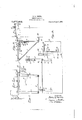
In order to comprehend the invention referen-ce should be had to the accompanying sheet of drawings, wherein- Figure 1 is a broken front elevation illustating the attachment as applied to a winow. i
Fig. 2 is an end elevation of the attachment illustrated as applied to a window, and
Fig. 3 is a partly broken away plan view of the attachment removed from the window.
In the drawings, the numeral 1 is used to designate a suitable size platform united in spaced relation relative to each other and are connected at their lower end portions by the tie rod member 3. To the upper inner end portion lof the frame members 3 are united by rivets 6 the angle brackets 7, the upper inwardly turned portion of said angle brackets, when the attachment is united to a window being adapted to rest on the upper surface of the window ledge 8. (Fig. 2 of the drawings.) The support structure as thus formed is adjustably held to the window sill 9 inside of the room by means of the angle clamps 10, which clamps are held to a connecting member 11 means of the wing nuts 12, which nuts screw onto the threaded studs 13 upwardly projected from the members 11 through the Slotted portions M of the clamps 10. The members 11 are connected to the members 111 by the hinged connections 15, and the said members 14 are hingedly united at 1G to the upwardly flanged portion 17 of the members 18 united by rivets 19 to the under surface of the platform 1. By reason of the articulated members 11 and 14, which constitute the connection between the platform 1 and the adjustable securing clamps 10, any irregularity of the window ledge 8 and window sill 9, is overcome thus adapting the support to be readily attached to the window sill 9 of windows having varying shaped ledges S, so that at all times the platform 1, when the support is applied to the window ,witll stand in horizontal position.
In order to compensate for the projection or overhang of the window ledge 8 relative to the exterior surface of the building wall 20, each member 3 of the frame structures for the platform 1 is provided with an inwardly projected extension 21, the inner end 22 of which is upwardly flanged so as to bear against the exterior surface of the wall 20 so that the members 3 will stand a lug extension substzmtially parallel with of .the Wall 20 when the support is applied to the Window sill.
For the holding of the Water pail and the Wash rags and to place the same Within convenient reach of the operator situated on the platforml l and' prevent the slopping or splashing of the Water fisoni the pail lonto the said platform l, there is united to one end of the said platform 'a supporting bracket 23, which is connected thereto by the hinges 2,4, the leaf members of the said hinges being' united to the under surface of the platforn'i l and the under surface of the bracket 23, respectively, by the con nections 25 and 26. Vlfhen in a raised ProSition7 the said bracket 23 lis supported by the link members 27 and 28,', .united respectively* to one of the members 3 anjd under surface of the bracket 23, and the said mein,- bers 27 and 2,8 are pivotally connected .by a zrule joint 29. The link 27 is provided With 30 which when the `links are extended to support the bracket 25 moves into engagement with the notched portion 31 of the link 2S when the Ibracket 23 is placed in raised position, and' by such engagement holds the links 27 ari- 1d y28 in locked engagement and prevents the donn- Ward movement of the said bracket 23' `ein the Weightof a filled bucket being placed thereon. i
It will be understood ythat when the device `is not in use the bracket 23 is swung downwardly Iin ,the position indicated b 74"the dotted lines in Fi l of the drawings.
Preferably tie members constituting the described support are made of metal, but the material' of Which thesame is formed is immaterial to the present -invention.V
Gopes pf this patent may be obtained for ve the outer surface Having thus described the invention, what is claimed as new and desi-red to be protected by Letters Patent of the United States, is
In a Window scaffold, the combination with a frame structure comprising ya pair of parallell spaced substantially triangular members, ,plattform resting at its opposite ends on the horizontal legs of said triangular members and connected thereto, a bracket carried bythe vertical leg Eof each of said Atriangular members, a portion of each of said brackets adaptedv for projecting` at right `angles to `the 1surface of said vertical fname legs and ,in a plane substantially parallel With tthe upper surface of said platform for engagement over the ledge of a window, and adnsnble penning new for `connecting the snpporting "structure to the sill of a. Window, a link piveted at one end to said Iclamping means and pivotally connected at its opposite end .t0 Said platform intermediate said triangnlar frame nlembers, the pivoted point of' 1connection of said link `and plkatfprn'i ,being in substantially horizontal alinemcnt with the heel of said brackets, whereby said clamping nlreans is capable of engagement with sills disposed in. varions planes Eabove or Melon7 said platf ferm wthontinterfering with ,the yengagement of lsaid brackets with the Window ledge. y
In testimony -Wliereof I have signed my naine to this speciiica-tion `inthe presence .of twosnbscribin'g Witnesses.J i
WILLIS Gr. MORQRS. Witnesses cents each, by `ad'r'es,sling the "Commissioner ,er Patents,
washington, D. el"
Priority Applications (1)
| Application Number | Priority Date | Filing Date | Title |
|---|---|---|---|
| US5508415A US1277458A (en) | 1915-10-09 | 1915-10-09 | Window-scaffold. |
Applications Claiming Priority (1)
| Application Number | Priority Date | Filing Date | Title |
|---|---|---|---|
| US5508415A US1277458A (en) | 1915-10-09 | 1915-10-09 | Window-scaffold. |
Publications (1)
| Publication Number | Publication Date |
|---|---|
| US1277458A true US1277458A (en) | 1918-09-03 |
Family
ID=3345056
Family Applications (1)
| Application Number | Title | Priority Date | Filing Date |
|---|---|---|---|
| US5508415A Expired - Lifetime US1277458A (en) | 1915-10-09 | 1915-10-09 | Window-scaffold. |
Country Status (1)
| Country | Link |
|---|---|
| US (1) | US1277458A (en) |
-
1915
- 1915-10-09 US US5508415A patent/US1277458A/en not_active Expired - Lifetime
Similar Documents
| Publication | Publication Date | Title |
|---|---|---|
| US1277458A (en) | Window-scaffold. | |
| US829537A (en) | Adjustable bracket for supporting platforms. | |
| US763209A (en) | Step-ladder. | |
| US1658942A (en) | Seat or platform for outside window cleaning | |
| US1518091A (en) | Window guard | |
| US1456362A (en) | Window scaffold | |
| US926320A (en) | Mechanic's adjustable trestle. | |
| US1541402A (en) | Safety device for ladders | |
| US279740A (en) | William a | |
| US539200A (en) | Adjustable window-scaffold | |
| US596427A (en) | rickey | |
| US933148A (en) | Step or platform attachment. | |
| US811514A (en) | Adjustable bracket for employment on windows, ladders, and parapets. | |
| US1318479A (en) | Saeety-rack eor window-washers | |
| US991182A (en) | Portable extension-scaffold. | |
| US1141749A (en) | Pendant-scaffold support. | |
| US363634A (en) | Folding ladder | |
| US557026A (en) | Platform | |
| US924744A (en) | Combined ironing-board and step-ladder. | |
| US1130417A (en) | Combined ironing-board and step-ladder. | |
| US268132A (en) | sandyos | |
| US759629A (en) | Window-chair. | |
| US266691A (en) | Window-platform and fire-escape | |
| US678115A (en) | Window-scaffold. | |
| US818268A (en) | Scaffold. |