US1237317A - Cake-turner. - Google Patents
Cake-turner. Download PDFInfo
- Publication number
- US1237317A US1237317A US8911216A US8911216A US1237317A US 1237317 A US1237317 A US 1237317A US 8911216 A US8911216 A US 8911216A US 8911216 A US8911216 A US 8911216A US 1237317 A US1237317 A US 1237317A
- Authority
- US
- United States
- Prior art keywords
- cake
- turner
- handle
- members
- blade
- Prior art date
- Legal status (The legal status is an assumption and is not a legal conclusion. Google has not performed a legal analysis and makes no representation as to the accuracy of the status listed.)
- Expired - Lifetime
Links
Images
Classifications
-
- A—HUMAN NECESSITIES
- A47—FURNITURE; DOMESTIC ARTICLES OR APPLIANCES; COFFEE MILLS; SPICE MILLS; SUCTION CLEANERS IN GENERAL
- A47J—KITCHEN EQUIPMENT; COFFEE MILLS; SPICE MILLS; APPARATUS FOR MAKING BEVERAGES
- A47J43/00—Implements for preparing or holding food, not provided for in other groups of this subclass
- A47J43/28—Other culinary hand implements, e.g. spatulas, pincers, forks or like food holders, ladles, skimming ladles, cooking spoons; Spoon-holders attached to cooking pots
- A47J43/283—Tongs; Devices for picking, holding or rotating food
Definitions
- Fig. 2 is a View in side elevation.
- My invention comprises a handle composed of the separate companion members 1, 2 Which are connected by the hub 3, the former member being hinged thereto at 3.
- the members 1, 2 are formed with relatively adjacent flat faces 4, 5 in whichthe oppositely disposed recesses 6, 7 are formed to receive the ends of the spiral expansion spring 8 the purpose of which is toyieldingly retain the handle 'members 1, 2 the maximum distance apart.
- An elongated recess 9 is formed in the face 4 to receive a link 10 one end of which is pivotally arranged upon a transverse pin 11 arranged in the said handle member 1 and passing throu h the said recess 9; the upper end of said fink 10 being pivotally secured to a reach rod 12 which extends through a perforation in the hub 3 and through a bore in a stem 13 carried by said hub, the opposite end of said rod 12 bein pivotally connected to the shank 14 of the lode 15, said shank being pivotally suspended in the angular bifurcated end 16 of the stem 13.
- the operation of the device is as follows: lVhen the handle members 1, 2 are pressed together against the tension of the spring 8 the member 2 bears against the reach rod 12 and link 10 and forces both toward the blade-end of the device moving the blade into the position'shown in Fig, 2 and turning the cake, which has previously been raised from the griddle upon said blade by inserting that member beneath the cake, in a quick and satisfactory manner.
- pressure is removed from the handle members 1, 2 they will, through the medium of spring 8, again assume the position shown in Fig. 1.
- a handle comprising a hinged member and a relatively fixed incinber; said hinged member being formed with a longitudinal recess, means for yieldingly retaining said members the maximum distance apart, a pin extending transversely through the recessed portion of said hinged member, a hollow stem connected to said handle and having an angular bifurcated termination, a blade, a shank carryin said blade and pivotally disposed in the ifurcated end of said stem, a reach rod movably disposed in said stem and connected to said shank, and a springepressed link connecting said reach rod and the aforesaid pin and disposed in the recessed portion of said hinged handle member whereby movement of said member with relation to the fixed handle member will impart movement to said reach rod.
- VALERIE EMANUEL FAG'ERFJEEOM VALERIE EMANUEL FAG'ERFJEEOM.
Landscapes
- Engineering & Computer Science (AREA)
- Mechanical Engineering (AREA)
- Food Science & Technology (AREA)
- Toys (AREA)
- Adornments (AREA)
Description
V. E. FAGERSTRQM. H
CAKE TURNER. APPLICATION FILED Ams. mus.
Patented Aug. 21, 1917.
Min 5.963
' UNITED snares earner canton VALFBID EMANUEL FAGERSTBOM, 0F DULUTH, MINNESOTA CAKE-TURNER.
Specification 01 Letters Patent.
Patented Au 21, rain Application filed April 5, 1916. Serial No. 89,112.
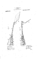
be hereinafter fully described in the ioll0wing specification, pointed out in the ap pended claim and illustrated in the accompanying drawin which forms a part of said specification an in which- Figure 1 is a perspective view of my improved cake turner.
Fig. 2 is a View in side elevation.
Like reference characters denote corresponding parts in both views.
My invention comprises a handle composed of the separate companion members 1, 2 Which are connected by the hub 3, the former member being hinged thereto at 3. The members 1, 2 are formed with relatively adjacent flat faces 4, 5 in whichthe oppositely disposed recesses 6, 7 are formed to receive the ends of the spiral expansion spring 8 the purpose of which is toyieldingly retain the handle 'members 1, 2 the maximum distance apart.- An elongated recess 9 is formed in the face 4 to receive a link 10 one end of which is pivotally arranged upon a transverse pin 11 arranged in the said handle member 1 and passing throu h the said recess 9; the upper end of said fink 10 being pivotally secured to a reach rod 12 which extends through a perforation in the hub 3 and through a bore in a stem 13 carried by said hub, the opposite end of said rod 12 bein pivotally connected to the shank 14 of the lode 15, said shank being pivotally suspended in the angular bifurcated end 16 of the stem 13. v r
The operation of the device is as follows: lVhen the handle members 1, 2 are pressed together against the tension of the spring 8 the member 2 bears against the reach rod 12 and link 10 and forces both toward the blade-end of the device moving the blade into the position'shown in Fig, 2 and turning the cake, which has previously been raised from the griddle upon said blade by inserting that member beneath the cake, in a quick and satisfactory manner. When pressure is removed from the handle members 1, 2 they will, through the medium of spring 8, again assume the position shown in Fig. 1.
What is claimed is In a cake turner, a handle comprising a hinged member and a relatively fixed incinber; said hinged member being formed with a longitudinal recess, means for yieldingly retaining said members the maximum distance apart, a pin extending transversely through the recessed portion of said hinged member, a hollow stem connected to said handle and having an angular bifurcated termination, a blade, a shank carryin said blade and pivotally disposed in the ifurcated end of said stem, a reach rod movably disposed in said stem and connected to said shank, and a springepressed link connecting said reach rod and the aforesaid pin and disposed in the recessed portion of said hinged handle member whereby movement of said member with relation to the fixed handle member will impart movement to said reach rod.
In testimony that I claim the'foregoiiig as my own I have hereto affixed my'sigha ture in the presence of two subscribing Witnesses; v
VALERIE EMANUEL FAG'ERFJEEOM.
Witnesses:
fiwMORTEMD, J. A. Mourners.
Priority Applications (1)
| Application Number | Priority Date | Filing Date | Title |
|---|---|---|---|
| US8911216A US1237317A (en) | 1916-04-05 | 1916-04-05 | Cake-turner. |
Applications Claiming Priority (1)
| Application Number | Priority Date | Filing Date | Title |
|---|---|---|---|
| US8911216A US1237317A (en) | 1916-04-05 | 1916-04-05 | Cake-turner. |
Publications (1)
| Publication Number | Publication Date |
|---|---|
| US1237317A true US1237317A (en) | 1917-08-21 |
Family
ID=3305136
Family Applications (1)
| Application Number | Title | Priority Date | Filing Date |
|---|---|---|---|
| US8911216A Expired - Lifetime US1237317A (en) | 1916-04-05 | 1916-04-05 | Cake-turner. |
Country Status (1)
| Country | Link |
|---|---|
| US (1) | US1237317A (en) |
Cited By (3)
| Publication number | Priority date | Publication date | Assignee | Title |
|---|---|---|---|---|
| US6530611B2 (en) * | 2001-06-01 | 2003-03-11 | Remco Technologies, Inc. | Pizza peel with rotatable blade |
| US20070271839A1 (en) * | 2006-05-29 | 2007-11-29 | Kuei-Tzu Su | Electronic mosquito racket |
| USD631206S1 (en) * | 2010-06-14 | 2011-01-18 | Jordan Michael Barry Parlee | Heat protection glove for hand-gripping implements |
-
1916
- 1916-04-05 US US8911216A patent/US1237317A/en not_active Expired - Lifetime
Cited By (3)
| Publication number | Priority date | Publication date | Assignee | Title |
|---|---|---|---|---|
| US6530611B2 (en) * | 2001-06-01 | 2003-03-11 | Remco Technologies, Inc. | Pizza peel with rotatable blade |
| US20070271839A1 (en) * | 2006-05-29 | 2007-11-29 | Kuei-Tzu Su | Electronic mosquito racket |
| USD631206S1 (en) * | 2010-06-14 | 2011-01-18 | Jordan Michael Barry Parlee | Heat protection glove for hand-gripping implements |
Similar Documents
| Publication | Publication Date | Title |
|---|---|---|
| US1237317A (en) | Cake-turner. | |
| US1259458A (en) | Clothes-pin. | |
| US1443138A (en) | Digging device | |
| US1832584A (en) | Toy building construction | |
| US1605008A (en) | Removable handle for scrubbing brushes and the like | |
| US1078533A (en) | Clamping device. | |
| US3417443A (en) | Curtain training clip | |
| US1595706A (en) | Dynamite tool | |
| US1142837A (en) | Handle connection. | |
| US1079998A (en) | Tobacco-cutter. | |
| US2488102A (en) | Cuff link | |
| US1828585A (en) | Undertaker's device | |
| US7386940B2 (en) | Hairdressing scissors and positioning device thereof | |
| US662468A (en) | Combined separating-spring and locking device for shears or the like. | |
| US1485510A (en) | Ice-pick holder | |
| US1323509A (en) | Fly catcher and swatter | |
| US1041729A (en) | Bracelet. | |
| US1778969A (en) | Cooky and doughnut cutter | |
| US1699253A (en) | Press for securing foundations in honey boxes | |
| US1846595A (en) | Automobile radiator ornament | |
| US1081170A (en) | Fruit-tree prop. | |
| US276424A (en) | Albeet c | |
| US1807801A (en) | Albert stenckeb | |
| US33971A (en) | Improvement in skirt-supporters | |
| US1369424A (en) | Tool rest or support |