US1237282A - Glass tank-furnace. - Google Patents
Glass tank-furnace. Download PDFInfo
- Publication number
- US1237282A US1237282A US83631114A US1914836311A US1237282A US 1237282 A US1237282 A US 1237282A US 83631114 A US83631114 A US 83631114A US 1914836311 A US1914836311 A US 1914836311A US 1237282 A US1237282 A US 1237282A
- Authority
- US
- United States
- Prior art keywords
- furnace
- tank
- wall
- walls
- glass
- Prior art date
- Legal status (The legal status is an assumption and is not a legal conclusion. Google has not performed a legal analysis and makes no representation as to the accuracy of the status listed.)
- Expired - Lifetime
Links
- 239000011521 glass Substances 0.000 title description 10
- 238000010276 construction Methods 0.000 description 6
- 238000013021 overheating Methods 0.000 description 5
- 230000001066 destructive effect Effects 0.000 description 2
- 239000004575 stone Substances 0.000 description 2
- 230000009471 action Effects 0.000 description 1
- 230000008901 benefit Effects 0.000 description 1
- 230000007547 defect Effects 0.000 description 1
- 230000003467 diminishing effect Effects 0.000 description 1
- 230000000694 effects Effects 0.000 description 1
- 239000000945 filler Substances 0.000 description 1
- 230000002452 interceptive effect Effects 0.000 description 1
- 230000004048 modification Effects 0.000 description 1
- 238000012986 modification Methods 0.000 description 1
- 230000008439 repair process Effects 0.000 description 1
- 125000006850 spacer group Chemical group 0.000 description 1
- 239000002699 waste material Substances 0.000 description 1
Images

Classifications
-
- F—MECHANICAL ENGINEERING; LIGHTING; HEATING; WEAPONS; BLASTING
- F27—FURNACES; KILNS; OVENS; RETORTS
- F27B—FURNACES, KILNS, OVENS OR RETORTS IN GENERAL; OPEN SINTERING OR LIKE APPARATUS
- F27B3/00—Hearth-type furnaces, e.g. of reverberatory type; Electric arc furnaces ; Tank furnaces
- F27B3/10—Details, accessories or equipment, e.g. dust-collectors, specially adapted for hearth-type furnaces
- F27B3/12—Working chambers or casings; Supports therefor
-
- F—MECHANICAL ENGINEERING; LIGHTING; HEATING; WEAPONS; BLASTING
- F27—FURNACES; KILNS; OVENS; RETORTS
- F27D—DETAILS OR ACCESSORIES OF FURNACES, KILNS, OVENS OR RETORTS, IN SO FAR AS THEY ARE OF KINDS OCCURRING IN MORE THAN ONE KIND OF FURNACE
- F27D1/00—Casings; Linings; Walls; Roofs
Definitions
- WILLIAM e. BERGMAN, OE TOLEDO, OHIO, AssIGNOE To THE TOLEDO GLAss coMrAnr.
- the invention relates to glass furnaces of the tank form, and it is-the object of the invention to produce higher efficiency with less destructive action upon vthe tank.v I n the present state of the art it is usual in glass furnacevconstruction to form the tank and furnace chamber of different materia-ls.
- Figure l is a vertical section through one of the sides of a glass tank and furnace
- Fig. 2 is a similar view Vshowing a modified constructlon
- FIG. 3 A is the wall. of the tank, B is the cap or tuck-stone for said tankand C is the side wall of the furnace which. supports the arch D.
- This side wall C is shown as arranged outside of the tank wall A, but instead of supporting it upon a girder adjacent to the tank wall a metallic angle bar D is employed for that purpose.
- This angle bar is arranged with its lower wing' fiush with the bottom of the wall C and without overlapping to any materialen# tent the tank wall A.
- the upwardlyex tending flange of the angle gives the necessary strength, and this may be attached to the buck-stays (not shown) to support the furnace independent of the tank.
- V which stays, in addition to supporting the furnacewail, are used to hold the tank walls 1n position.
- furnace chamber is shown with side Walls of y greater height, these walls being supported with sufficient clearance to prevent bindingl due to expansion Aof the walls when the furnace is under heat, but the clearance is not large enough to waste any considerable amount of the furnace heat.
- a tight -sealis formed between the furnace and the tank
Landscapes
- Engineering & Computer Science (AREA)
- Mechanical Engineering (AREA)
- General Engineering & Computer Science (AREA)
- Furnace Housings, Linings, Walls, And Ceilings (AREA)
Description
W. G. BERGIVIAN. GLASS TANK FURNACE.
, APPLICATION FILED MAY 4. 1914. 1,237,282. 611A SHEETS` ET l III, I III, ."I
Aff
I BV
W. G, BBBBBB N. GLASS TANK- FURNACl-.V
l APPLICATION FILED MAY 4. |914. 1,237,282. rammed Aug. 21,1917.
` 2 5 EEEEEEEEE n 2. 1
I/ l J2 --ffl UNITED STATES ,PATENT oEEroE. y
WILLIAM: e. BERGMAN, OE TOLEDO, OHIO, AssIGNOE To THE TOLEDO GLAss coMrAnr.
OE TOLEDO, ojrio, A CORPORATION OE OHIO.
GLAss TANKAEURNAOE.
Specification of Letters Patent.
Application led May 4, 1914. Serial No. 836,311.
of Lucas and State of Ohio, have invented certain new and useful Improvements in Glass Tank-Furnaces, of which the following is a specification, reference being had therein to the accompanying drawings.
The invention relates to glass furnaces of the tank form, and it is-the object of the invention to produce higher efficiency with less destructive action upon vthe tank.v I n the present state of the art it is usual in glass furnacevconstruction to form the tank and furnace chamber of different materia-ls.
It is also usual to support the furnace which is above the tank independently of the latter, so that repairs may be made upon the tank without disturbing the furnace. To accomplish this result the walls of the furnace are usuallysupported upon girders or supporting beams which .are arranged outside of the tank walls, said beams in turny being supported by the buck-stays which hold the furnace walls -in position. A defect in furnaces of this construction is the destructive action upon the tank wall, which is due to overheating of the upper' portion thereof, such overheating being in turn due Ato the marginal heat in the furnace chamber and the shielding action of the supporting girders upon the outer face of the wall.
Thus the circulation of air which lowersthe temperature of the outer portion of theetank wall is obstructed'by the supporting girders at the very point where the inner portion of thel wall is subjected to the most intense heat, and as a result the wasting of the wall at this point is veryrapid. With my improved construction I first avoid any shielding of the tank wall upon its outer surface; and second, I avoid overheating the inner portion of the tank wall by diminishing the size of the furnace chamber to be flush with the inner face of the tank wall. This is accomplished without interfering with the independence of the furnace fromy the tank, and an additional advantage obtained is the conservation of heat due to the smaller chamber. l
In the drawings:
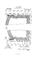
Figure l is a vertical section through one of the sides of a glass tank and furnace;
Fig. 2 is a similar view Vshowing a modified constructlon; and
Patented Aug. 21, 1917. i
Figs. 3 and are similar views showing j still other modifications. f
As shown in Fig. 3 A is the wall. of the tank, B is the cap or tuck-stone for said tankand C is the side wall of the furnace which. supports the arch D. This side wall C is shown as arranged outside of the tank wall A, but instead of supporting it upon a girder adjacent to the tank wall a metallic angle bar D is employed for that purpose. This angle bar is arranged with its lower wing' fiush with the bottom of the wall C and without overlapping to any materialen# tent the tank wall A. The upwardlyex tending flange of the angle gives the necessary strength, and this may be attached to the buck-stays (not shown) to support the furnace independent of the tank.
The construction just described, while avoiding the shielding effect on the outer surface 'of the tank wall is nevertheless open to the objection that the inner face of the wall and the tuck-stone are subjectedto overheating. This I lhave avoided in the construction shown in Figs. l, 2 and i byA arranging the side walls of the furnace 1n alinement with the side wail of the tank. As shown in Fig. 1, E is a supporting girder arranged adjacent to the outer face ofthe furnace wall anriupporting the base' blocks F of the arch wall D. The girders-E are attached by brackets Gr to the buck-stays H,
Vwhich stays, in addition to supporting the furnacewail, are used to hold the tank walls 1n position. i
In the construction shown in Fig. 2, the.
furnace chamber is shown with side Walls of y greater height, these walls being supported with sufficient clearance to prevent bindingl due to expansion Aof the walls when the furnace is under heat, but the clearance is not large enough to waste any considerable amount of the furnace heat. In the construction Vshown in Fig. 4, a tight -sealis formed between the furnace and the tank,
loo
Within the furnace chamber is effective upon the glass and is not Wasted upon the tank Walls. Also the furnace so constructed is longer lived, as overheating ofthe tank Walls is prevented. I What I claim as my invention is;-
l. In a glass furnace, the combination Withthe tank, of a fsuperposed furnace having side walls substantially flush with the tank Walls, a metallic bar or girder for supporting said side walls, buck-stays spacedfrom the tank Walls, and brackets or spacers secured to said` buck-stays and supporting bars intermediate the same, the lower sides of said bars and said brackets being [subopies of this patent may be obtained for ve cents each, by addressing the Washington, D. C.
sta-ntially flush with the lower sides of said Walls.
2. In a glass furnace, the combination.
a nd tank Walls.
3. In a glass furnace, the combinationv with the tank, of a superposed furnace, means for supporting the furnace Wall independent of the tank Wall, and filler blocks between said tank `vvall and furnace Wall comprisingl reverse wedges adjustable to completely fill the space. y
In testimony whereof I 'aflix my signature in presence of two Witnesses.
IVILLIAM G. BERGMAN. lVitnesses:
T. H. MILLER, S. E. EICHMAN.
Commissioner of lPatents,
Priority Applications (1)
| Application Number | Priority Date | Filing Date | Title |
|---|---|---|---|
| US83631114A US1237282A (en) | 1914-05-04 | 1914-05-04 | Glass tank-furnace. |
Applications Claiming Priority (1)
| Application Number | Priority Date | Filing Date | Title |
|---|---|---|---|
| US83631114A US1237282A (en) | 1914-05-04 | 1914-05-04 | Glass tank-furnace. |
Publications (1)
| Publication Number | Publication Date |
|---|---|
| US1237282A true US1237282A (en) | 1917-08-21 |
Family
ID=3305101
Family Applications (1)
| Application Number | Title | Priority Date | Filing Date |
|---|---|---|---|
| US83631114A Expired - Lifetime US1237282A (en) | 1914-05-04 | 1914-05-04 | Glass tank-furnace. |
Country Status (1)
| Country | Link |
|---|---|
| US (1) | US1237282A (en) |
Cited By (2)
| Publication number | Priority date | Publication date | Assignee | Title |
|---|---|---|---|---|
| US4155703A (en) * | 1976-02-25 | 1979-05-22 | Eisenwerk-Gesellschaft Maximillianshutte mbH. | Lining truncated cone walls by means of refractory bricks |
| US5445661A (en) * | 1990-12-12 | 1995-08-29 | Beteiligungen Sorg Gmbh & Co. Kg | Melting end for glass melting furnaces with soldier blocks and operating process therefor |
-
1914
- 1914-05-04 US US83631114A patent/US1237282A/en not_active Expired - Lifetime
Cited By (2)
| Publication number | Priority date | Publication date | Assignee | Title |
|---|---|---|---|---|
| US4155703A (en) * | 1976-02-25 | 1979-05-22 | Eisenwerk-Gesellschaft Maximillianshutte mbH. | Lining truncated cone walls by means of refractory bricks |
| US5445661A (en) * | 1990-12-12 | 1995-08-29 | Beteiligungen Sorg Gmbh & Co. Kg | Melting end for glass melting furnaces with soldier blocks and operating process therefor |
Similar Documents
| Publication | Publication Date | Title |
|---|---|---|
| US1237282A (en) | Glass tank-furnace. | |
| US2007038A (en) | Furnace construction | |
| US668797A (en) | Arch-skewback. | |
| US969752A (en) | Deflector for furnaces. | |
| US1069973A (en) | Front arch for locomotive-furnaces. | |
| US1982797A (en) | Stoker furnace construction | |
| US1655680A (en) | Furnace construction | |
| US253192A (en) | Furnace | |
| US1540069A (en) | Furnace construction | |
| US997977A (en) | Furnace-casing. | |
| US2093212A (en) | Muffle construction | |
| US1437328A (en) | Tile for furnace grates of the checkerboard type | |
| US1086467A (en) | Fire-arch for furnaces. | |
| US558206A (en) | playfoed | |
| US323876A (en) | Fkank | |
| US660181A (en) | Straw-burning furnace. | |
| US1094702A (en) | Furnace-front. | |
| US576872A (en) | Metallic arch for furnace-fronts | |
| US528229A (en) | Steam-boiler furnace | |
| US1323038A (en) | foote | |
| US1259215A (en) | Heating-furnace. | |
| US1073919A (en) | Rectangular gas-producer. | |
| US1019155A (en) | Furnace-front. | |
| US835596A (en) | Fire-brick tile. | |
| US1138044A (en) | Locomotive-furnace arch. |