US12354792B2 - Magnet structure with improved performance, inverter, and associated method - Google Patents
Magnet structure with improved performance, inverter, and associated method Download PDFInfo
- Publication number
- US12354792B2 US12354792B2 US18/717,871 US202318717871A US12354792B2 US 12354792 B2 US12354792 B2 US 12354792B2 US 202318717871 A US202318717871 A US 202318717871A US 12354792 B2 US12354792 B2 US 12354792B2
- Authority
- US
- United States
- Prior art keywords
- magnet
- angle
- magnet structure
- equal
- magnets
- Prior art date
- Legal status (The legal status is an assumption and is not a legal conclusion. Google has not performed a legal analysis and makes no representation as to the accuracy of the status listed.)
- Active
Links
Images


Classifications
-
- H—ELECTRICITY
- H01—ELECTRIC ELEMENTS
- H01F—MAGNETS; INDUCTANCES; TRANSFORMERS; SELECTION OF MATERIALS FOR THEIR MAGNETIC PROPERTIES
- H01F7/00—Magnets
- H01F7/02—Permanent magnets [PM]
- H01F7/0273—Magnetic circuits with PM for magnetic field generation
-
- H—ELECTRICITY
- H01—ELECTRIC ELEMENTS
- H01F—MAGNETS; INDUCTANCES; TRANSFORMERS; SELECTION OF MATERIALS FOR THEIR MAGNETIC PROPERTIES
- H01F7/00—Magnets
- H01F7/02—Permanent magnets [PM]
- H01F7/0205—Magnetic circuits with PM in general
- H01F7/021—Construction of PM
-
- H—ELECTRICITY
- H05—ELECTRIC TECHNIQUES NOT OTHERWISE PROVIDED FOR
- H05H—PLASMA TECHNIQUE; PRODUCTION OF ACCELERATED ELECTRICALLY-CHARGED PARTICLES OR OF NEUTRONS; PRODUCTION OR ACCELERATION OF NEUTRAL MOLECULAR OR ATOMIC BEAMS
- H05H7/00—Details of devices of the types covered by groups H05H9/00, H05H11/00, H05H13/00
- H05H7/04—Magnet systems, e.g. undulators, wigglers; Energisation thereof
- H05H2007/041—Magnet systems, e.g. undulators, wigglers; Energisation thereof for beam bunching, e.g. undulators
Definitions
- the present invention relates to a magnet structure. It also relates to an undulator comprising such a structure, as well as an associated method.
- Such a device allows a user to generate a magnetic field.
- the field of the invention is more particularly, but not limited to, that of particle accelerators.
- An undulator is a device that generates a spatially periodic magnetic field. When charged particles (generally electrons) pass through this device, they are subjected to a force that imparts an oscillating movement to them and generates an electromagnetic wave. Due to its spectral and optical qualities, the radiation emitted, called synchrotron radiation, is used as a tool for probing material in numerous scientific fields (biology, chemistry, etc.). Undulators are characterized by their spatial period and their magnetic field, main parameters that impact the spectral extent of the emitted radiation. APPLE and associated undulators (APPLE I, II, III, X, Delta, etc.) produce a vertical and/or horizontal periodic magnetic field for generating linear polarization (pure or inclined) or circular polarization.
- APPLE I, II, III, X, Delta, etc. produce a vertical and/or horizontal periodic magnetic field for generating linear polarization (pure or inclined) or circular polarization.
- the permanent magnets consist of rows of permanent magnets; moving two of them that are diagonally opposite makes it possible to change the phase between the field components, as well as their intensity and therefore to vary the helicity of the polarization.
- the permanent magnets are assembled in accordance with a Halbach structure. The latter consists in alternating permanent magnets whose magnetization vector rotates by 90° in the beam direction around the horizontal axis of the undulator, each magnet being magnetized in one direction at most. These permanent magnets are generally difficult to maintain in position because they repel one another or are in unstable equilibrium.
- each magnet is generally held just by means of a mechanical flange.
- this single flange no longer suffices because the thickness of the magnet is insufficient.
- the permanent magnets are then bonded in pairs, or even welded.
- the magnetization vector rotates from one magnet to another by 90° around the horizontal axis if four magnets are used to form the period.
- APPLE undulators consist of four longitudinally mobile beams to vary the phase between the field components and therefore the polarization of the electrons, or vertically (low vs high) in order to modify the strength of the magnetic field and therefore the resonance energy of the undulator.
- the two low rows have the same sequence of magnets, while on the upper beams, the magnets magnetized longitudinally are in the opposite direction to the low beams.
- the benefit of the APPLE undulators is to be able to vary the polarization in linear or circular mode.
- the horizontal and vertical field components are not equal, the resonance energy is then bounded by the value of the lowest magnetic field component.
- the number N of sets is equal to 4 or 6.
- the sets may further comprise:
- G x may be comprised in the interval [1 mm; 250 mm], preferably in the interval [1 mm; 50 mm], and/or G z is comprised in the interval [1 mm; 250 mm], preferably in the interval [1 mm; 50 mm].
- a method for generating a magnetic field characterized in that it is generated by means of a magnet structure according to the invention or an undulator according to the invention.
- FIG. 4 shows:
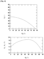
- FIG. 6 obtained on the same principle as the upper part of FIG. 4 or the lower part of FIG. 5 , shows the angle ⁇ s as a function of the angle ⁇ x for values of ⁇ s and ⁇ x for which the component B z in the direction Z of the magnetic field generated by the magnet structure 100 is equal to the component B x in the direction X of the magnetic field generated by the magnet structure 100 , with different curves corresponding to different values of the distance G.
- FIG. 8 shows:
- FIG. 9 shows the angle ⁇ s as a function of the angle ⁇ x for different values of spatial period Au, and for which the component B z in the direction Z of the magnetic field generated by the magnet structure 100 is equal to the component B x in the direction X of the magnetic field generated by the magnet structure 100 and maximum
- FIG. 10 shows on the vertical axis values of angle ⁇ corresponding to ⁇ x or ⁇ s :
- FIG. 11 shows the values of the magnetic fields B x and B z generated by the structure 100 as a function of the longitudinal position S at the center of the four magnets of each set 1 , 2 , 3 or 4 , out of vacuum or in the center of a vacuum chamber of the undulator 1000 comprising the structure 100 ,
- FIG. 15 is a profile view of six sets 1 , 5 , 2 , 3 , 6 , and 4 of magnets (each set comprising a magnet of one of the beams 10 , 20 , 30 , 40 ) of a second embodiment of a magnet structure 200 according to the invention; in this figure, each magnet is represented by a rectangle with rounded corners and has a direction of its permanent magnetization vector, projected in the plane of FIG. 15 comprising the directions S and Z, shown by an arrow inside the rectangle of this magnet,
- FIG. 18 shows the angle ⁇ s as a function of the angle ⁇ x for different values of spatial period ⁇ u , and for which the component B z in the direction Z of the magnetic field generated by the magnet structure 200 is equal to the component B x in the direction X of the magnetic field generated by the magnet structure 200 and maximum
- FIG. 19 shows, on the vertical axis, values of angle ⁇ corresponding to ⁇ x or ⁇ s :
- variants of the invention comprise only a selection of the features disclosed or shown hereinafter in isolation from the other features disclosed or shown (even if that selection is isolated within a phrase comprising other features), if this selection of features is sufficient to confer a technical benefit or to differentiate the invention with respect to the prior state of the art.
- This selection comprises at least one preferably functional feature which lacks structural details, and/or only has a portion of the structural details if that portion is only sufficient to confer a technical benefit or to differentiate the invention with respect to the prior state of the art.
- the fourth beam 40 and the first beam 10 follow one another along the direction X.
- the magnetization vector (which leads to permanent magnetization, but not to a temporary magnetization of an electromagnet), of each magnet of each beam 10 , 20 , 30 , 40 has a non-zero component along each of the directions X, S and Z.
- ⁇ x is different from 0°, 90°, 180° or 270°, preferably to +1°, even preferably to ⁇ 5°.
- ⁇ s is different from 0°, 90°, 180° or 270°, preferably to +1°, even preferably to +5°.
- FIG. 4 shows:
- FIG. 4 is obtained by digital simulation by means of a magnetic field simulation software (RADIA) that calculates the magnetic field generated by a permanent magnet or a sequencing of permanent magnets with the following assumptions:
- RADIA magnetic field simulation software
- FIG. 5 is obtained by digital simulation by means of a magnetic field simulation software (RADIA) that calculates the magnetic field generated by a permanent magnet or a sequencing of permanent magnets with the following assumptions:
- RADIA magnetic field simulation software
- G x is equal, or substantially equal, to ⁇ 500 ⁇ m, preferably to within ⁇ 200 ⁇ m, at G z , and is noted in this case in the present distance description (also called air gap) G.
- FIG. 9 is obtained by digital simulation by means of a magnetic field simulation software (RADIA) that calculates the magnetic field generated by a permanent magnet or a sequencing of permanent magnets with the following assumptions:
- RADIA magnetic field simulation software
- FIG. 10 is obtained by digital simulation by means of a magnetic field simulation software (RADIA) that calculates the magnetic field generated by a permanent magnet or a sequencing of permanent magnets with the following assumptions:
- RADIA magnetic field simulation software
- ⁇ x ⁇ ( G ; ⁇ u ) Offset ⁇ 1 + AGap ⁇ 1 * exp ⁇ ( BGap ⁇ 2 * G ) + APeriod ⁇ 1 * exp ⁇ ( BPeriod ⁇ 1 * ⁇ u ) ⁇ to ⁇ within ⁇ 10 ⁇ % , preferably ⁇ to ⁇ within ⁇ 5 ⁇ % where:
- G is expressed in mm and ⁇ u is expressed in mm.
- G is expressed in mm and Au is expressed in mm.
- the structure 100 is preferably arranged to generate a magnetic field with its component B z along the direction Z equal, or substantially equal, to ⁇ 5%, preferably to ⁇ 1% with minimum air gap, to its component B x along the X direction.
- an undulator 1000 (not shown) according to the invention is constructed comprising:
- a magnetic field is generated by means of the magnet structure 100 or 200 or of the undulator 1000 .
- the magnetic field is generated with its component B z along the direction Z equal, or substantially equal, to +5%, preferably to +1% with minimum air gap, to its component B x along the X direction.
- FIG. 11 which shows the fields B x and B z obtained by the structure 100 , is obtained by digital simulation by means of a magnetic field calculation software (RADIA) which calculates the magnetic field generated by a permanent magnet or a sequencing of permanent magnets with the following assumptions:
- RADIA magnetic field calculation software
- the proposed new structure 100 or 200 produces a magnetic field (with an elliptical polarization) as large as the Halbach structure and makes it possible to address the problem of retention of the magnets.
- all the magnets are magnetized along 3 directions (vertical, horizontal and longitudinal). The fact of tilting the magnetization vector in the longitudinal direction makes it possible to keep two magnets naturally bonded. It is thus easier to retain a block of two bonded magnets naturally than a single magnet less thick subjected to opposite forces or two magnets bonded by other non-natural means (welding, adhesive, screws, etc.).
- the new structure 100 or 200 proposed makes it possible to respond to this problem, while maintaining the fact that the field components B z , B x in the two planes are always equivalent.
- the directions of the magnetization vectors of the magnets of the sets 1 , 23 , 3 and 4 do not change relative to the structure 100 .
- the magnetization vector of each magnet of each beam has a non-zero component along each of the directions X, S and Z.
- FIG. 17 is obtained by digital simulation by means of a magnetic field simulation software (RADIA) that calculates the magnetic field generated by a permanent magnet or a sequencing of permanent magnets with the following assumptions:
- RADIA magnetic field simulation software
- FIG. 18 is obtained by digital simulation by means of a magnetic field simulation software (RADIA) that calculates the magnetic field generated by a permanent magnet or a sequencing of permanent magnets with the following assumptions:
- RADIA magnetic field simulation software
- FIG. 19 is obtained by digital simulation by means of a magnetic field simulation software (RADIA) that calculates the magnetic field generated by a permanent magnet or a sequencing of permanent magnets with the following assumptions:
- RADIA magnetic field simulation software
- ⁇ x is typically within the interval ]5°; 80°], preferably in the interval [28°; 72°].
- ⁇ s is typically within the interval ]5°; 43°[, preferably in the interval [34°; 42°].
- G is expressed in mm and Au is expressed in mm.
- G is expressed in mm and Au is expressed in mm.
Landscapes
- Physics & Mathematics (AREA)
- Engineering & Computer Science (AREA)
- Optics & Photonics (AREA)
- Plasma & Fusion (AREA)
- Spectroscopy & Molecular Physics (AREA)
- Electromagnetism (AREA)
- Power Engineering (AREA)
- Particle Accelerators (AREA)
- Magnetic Resonance Imaging Apparatus (AREA)
- Hard Magnetic Materials (AREA)
Applications Claiming Priority (4)
| Application Number | Priority Date | Filing Date | Title |
|---|---|---|---|
| FRFR2205787 | 2022-06-14 | ||
| FR2205787A FR3136586B1 (fr) | 2022-06-14 | 2022-06-14 | Structure d’aimants à tenue améliorée, onduleur, et procédé associé. |
| FR2205787 | 2022-06-14 | ||
| PCT/EP2023/065735 WO2023242162A1 (fr) | 2022-06-14 | 2023-06-13 | Structure d'aimants à tenue améliorée, onduleur, et procédé associé |
Publications (2)
| Publication Number | Publication Date |
|---|---|
| US20250104896A1 US20250104896A1 (en) | 2025-03-27 |
| US12354792B2 true US12354792B2 (en) | 2025-07-08 |
Family
ID=83996395
Family Applications (1)
| Application Number | Title | Priority Date | Filing Date |
|---|---|---|---|
| US18/717,871 Active US12354792B2 (en) | 2022-06-14 | 2023-06-13 | Magnet structure with improved performance, inverter, and associated method |
Country Status (6)
| Country | Link |
|---|---|
| US (1) | US12354792B2 (pl) |
| EP (1) | EP4434063B1 (pl) |
| ES (1) | ES3046887T3 (pl) |
| FR (1) | FR3136586B1 (pl) |
| PL (1) | PL4434063T3 (pl) |
| WO (1) | WO2023242162A1 (pl) |
Citations (3)
| Publication number | Priority date | Publication date | Assignee | Title |
|---|---|---|---|---|
| US5383049A (en) | 1993-02-10 | 1995-01-17 | The Board Of Trustees Of Leland Stanford University | Elliptically polarizing adjustable phase insertion device |
| US5420556A (en) * | 1991-08-12 | 1995-05-30 | Sumitomo Electric Industries, Ltd. | Multipolar wiggler |
| US20120256715A1 (en) * | 2008-04-04 | 2012-10-11 | Correlated Magnetics Research, Llc | Magnetic attachment system |
-
2022
- 2022-06-14 FR FR2205787A patent/FR3136586B1/fr active Active
-
2023
- 2023-06-13 US US18/717,871 patent/US12354792B2/en active Active
- 2023-06-13 WO PCT/EP2023/065735 patent/WO2023242162A1/fr not_active Ceased
- 2023-06-13 PL PL23735594.6T patent/PL4434063T3/pl unknown
- 2023-06-13 EP EP23735594.6A patent/EP4434063B1/fr active Active
- 2023-06-13 ES ES23735594T patent/ES3046887T3/es active Active
Patent Citations (3)
| Publication number | Priority date | Publication date | Assignee | Title |
|---|---|---|---|---|
| US5420556A (en) * | 1991-08-12 | 1995-05-30 | Sumitomo Electric Industries, Ltd. | Multipolar wiggler |
| US5383049A (en) | 1993-02-10 | 1995-01-17 | The Board Of Trustees Of Leland Stanford University | Elliptically polarizing adjustable phase insertion device |
| US20120256715A1 (en) * | 2008-04-04 | 2012-10-11 | Correlated Magnetics Research, Llc | Magnetic attachment system |
Non-Patent Citations (3)
| Title |
|---|
| International Search Report and Written Opinion received for PCT/EP2023/065735, mailed Oct. 6, 2023. (Translator Declaration included). |
| Liang X., et al., "Analysis of the first magnetic results of the PSI APPLE X undulators in elliptical polarisation," Nuclear Instruments & Methods in Physics Research, Section A, vol. 987, Oct. 16, 2020, 10 pages. |
| Sasaki, S., et al., "Design of a New Type of Planar Undulator for Generating Variably Polarized Radiation," Nuclear Instruments & Methods in Physics Research, Section A, vol. 331, No. 1, Jul. 1, 1993, pp. 763-767. |
Also Published As
| Publication number | Publication date |
|---|---|
| EP4434063B1 (fr) | 2025-08-06 |
| FR3136586B1 (fr) | 2024-05-24 |
| WO2023242162A1 (fr) | 2023-12-21 |
| PL4434063T3 (pl) | 2025-11-12 |
| EP4434063C0 (fr) | 2025-08-06 |
| EP4434063A1 (fr) | 2024-09-25 |
| FR3136586A1 (fr) | 2023-12-15 |
| ES3046887T3 (en) | 2025-12-02 |
| US20250104896A1 (en) | 2025-03-27 |
Similar Documents
| Publication | Publication Date | Title |
|---|---|---|
| US5383049A (en) | Elliptically polarizing adjustable phase insertion device | |
| Shiltsev et al. | Considerations on compensation of beam-beam effects in the Tevatron with electron beams | |
| US5672879A (en) | System and method for producing superimposed static and time-varying magnetic fields | |
| JP2908220B2 (ja) | 常電導型偏向電磁石 | |
| Ito et al. | Coherent resonance stop bands in alternating gradient beam transport | |
| Quimby et al. | Development of a 10-meter Wedged-pole undulator | |
| US12354792B2 (en) | Magnet structure with improved performance, inverter, and associated method | |
| JPH0793200B2 (ja) | 多極ウィグラ | |
| Bahrdt | Shaping photon beams with undulators and wigglers | |
| Shiltsev et al. | Electron beam distortions in beam-beam compensation setup | |
| JPH0992498A (ja) | 挿入光源装置用磁気回路 | |
| Steiner et al. | Wien filter as a spin rotator at low energy | |
| Levichev et al. | Undulators and other insertion devices | |
| Smolyakov | Planar microundulator with rectangular grooved poles | |
| WO2010146628A1 (ja) | 挿入光源 | |
| JPH02174099A (ja) | 超電導偏向電磁石 | |
| JPH10270197A (ja) | 永久磁石型偏向磁石装置および電子蓄積リング | |
| Cremer et al. | Planar permanent magnet multipoles: measurements and configurations | |
| Tatchyn | Planar permanent magnet multipoles for particle accelerator and storage ring applications | |
| Pfluger | Insertion devices for 4/sup th/generation light sources | |
| US12046417B2 (en) | Multipole magnet | |
| Cobb et al. | Tests of planar permanent magnet multipole focusing elements | |
| JP4002977B2 (ja) | Ffag加速器 | |
| Bahrdt | Insertion devices | |
| Skachkov et al. | Quasi-sheet quadrupole triplets |
Legal Events
| Date | Code | Title | Description |
|---|---|---|---|
| AS | Assignment |
Owner name: SYNCHROTRON SOLEIL, FRANCE Free format text: ASSIGNMENT OF ASSIGNORS INTEREST;ASSIGNORS:VALLEAU, MATHIEU;GHAITH, AMIN;COUPRIE, MARIE-EMMANUELLE;SIGNING DATES FROM 20230904 TO 20230906;REEL/FRAME:067659/0093 |
|
| FEPP | Fee payment procedure |
Free format text: ENTITY STATUS SET TO UNDISCOUNTED (ORIGINAL EVENT CODE: BIG.); ENTITY STATUS OF PATENT OWNER: SMALL ENTITY |
|
| FEPP | Fee payment procedure |
Free format text: ENTITY STATUS SET TO SMALL (ORIGINAL EVENT CODE: SMAL); ENTITY STATUS OF PATENT OWNER: SMALL ENTITY |
|
| STCF | Information on status: patent grant |
Free format text: PATENTED CASE |