US12343809B2 - Reciprocating tool having orbit function - Google Patents
Reciprocating tool having orbit function Download PDFInfo
- Publication number
- US12343809B2 US12343809B2 US17/654,130 US202217654130A US12343809B2 US 12343809 B2 US12343809 B2 US 12343809B2 US 202217654130 A US202217654130 A US 202217654130A US 12343809 B2 US12343809 B2 US 12343809B2
- Authority
- US
- United States
- Prior art keywords
- reciprocating
- mode
- coupled
- bushing
- power tool
- Prior art date
- Legal status (The legal status is an assumption and is not a legal conclusion. Google has not performed a legal analysis and makes no representation as to the accuracy of the status listed.)
- Active, expires
Links
Images


Classifications
-
- B—PERFORMING OPERATIONS; TRANSPORTING
- B23—MACHINE TOOLS; METAL-WORKING NOT OTHERWISE PROVIDED FOR
- B23D—PLANING; SLOTTING; SHEARING; BROACHING; SAWING; FILING; SCRAPING; LIKE OPERATIONS FOR WORKING METAL BY REMOVING MATERIAL, NOT OTHERWISE PROVIDED FOR
- B23D49/00—Machines or devices for sawing with straight reciprocating saw blades, e.g. hacksaws
- B23D49/10—Hand-held or hand-operated sawing devices with straight saw blades
- B23D49/16—Hand-held or hand-operated sawing devices with straight saw blades actuated by electric or magnetic power or prime movers
- B23D49/162—Pad sawing devices
- B23D49/165—Pad sawing devices with means to move the saw blades in an orbital path
-
- B—PERFORMING OPERATIONS; TRANSPORTING
- B23—MACHINE TOOLS; METAL-WORKING NOT OTHERWISE PROVIDED FOR
- B23D—PLANING; SLOTTING; SHEARING; BROACHING; SAWING; FILING; SCRAPING; LIKE OPERATIONS FOR WORKING METAL BY REMOVING MATERIAL, NOT OTHERWISE PROVIDED FOR
- B23D49/00—Machines or devices for sawing with straight reciprocating saw blades, e.g. hacksaws
- B23D49/10—Hand-held or hand-operated sawing devices with straight saw blades
- B23D49/16—Hand-held or hand-operated sawing devices with straight saw blades actuated by electric or magnetic power or prime movers
- B23D49/162—Pad sawing devices
- B23D49/167—Pad sawing devices with means to adjust the guide plate or with means to adjust the plane in which the saw blade moves
-
- B—PERFORMING OPERATIONS; TRANSPORTING
- B23—MACHINE TOOLS; METAL-WORKING NOT OTHERWISE PROVIDED FOR
- B23D—PLANING; SLOTTING; SHEARING; BROACHING; SAWING; FILING; SCRAPING; LIKE OPERATIONS FOR WORKING METAL BY REMOVING MATERIAL, NOT OTHERWISE PROVIDED FOR
- B23D51/00—Sawing machines or sawing devices working with straight blades, characterised only by constructional features of particular parts; Carrying or attaching means for tools, covered by this subclass, which are connected to a carrier at both ends
- B23D51/16—Sawing machines or sawing devices working with straight blades, characterised only by constructional features of particular parts; Carrying or attaching means for tools, covered by this subclass, which are connected to a carrier at both ends of drives or feed mechanisms for straight tools, e.g. saw blades, or bows
- B23D51/161—Sawing machines or sawing devices working with straight blades, characterised only by constructional features of particular parts; Carrying or attaching means for tools, covered by this subclass, which are connected to a carrier at both ends of drives or feed mechanisms for straight tools, e.g. saw blades, or bows with dynamic balancing
-
- B—PERFORMING OPERATIONS; TRANSPORTING
- B23—MACHINE TOOLS; METAL-WORKING NOT OTHERWISE PROVIDED FOR
- B23D—PLANING; SLOTTING; SHEARING; BROACHING; SAWING; FILING; SCRAPING; LIKE OPERATIONS FOR WORKING METAL BY REMOVING MATERIAL, NOT OTHERWISE PROVIDED FOR
- B23D51/00—Sawing machines or sawing devices working with straight blades, characterised only by constructional features of particular parts; Carrying or attaching means for tools, covered by this subclass, which are connected to a carrier at both ends
- B23D51/16—Sawing machines or sawing devices working with straight blades, characterised only by constructional features of particular parts; Carrying or attaching means for tools, covered by this subclass, which are connected to a carrier at both ends of drives or feed mechanisms for straight tools, e.g. saw blades, or bows
- B23D51/166—Devices for arresting movement of the saw blades
-
- B—PERFORMING OPERATIONS; TRANSPORTING
- B25—HAND TOOLS; PORTABLE POWER-DRIVEN TOOLS; MANIPULATORS
- B25F—COMBINATION OR MULTI-PURPOSE TOOLS NOT OTHERWISE PROVIDED FOR; DETAILS OR COMPONENTS OF PORTABLE POWER-DRIVEN TOOLS NOT PARTICULARLY RELATED TO THE OPERATIONS PERFORMED AND NOT OTHERWISE PROVIDED FOR
- B25F5/00—Details or components of portable power-driven tools not particularly related to the operations performed and not otherwise provided for
- B25F5/001—Gearings, speed selectors, clutches or the like specially adapted for rotary tools
-
- B—PERFORMING OPERATIONS; TRANSPORTING
- B23—MACHINE TOOLS; METAL-WORKING NOT OTHERWISE PROVIDED FOR
- B23D—PLANING; SLOTTING; SHEARING; BROACHING; SAWING; FILING; SCRAPING; LIKE OPERATIONS FOR WORKING METAL BY REMOVING MATERIAL, NOT OTHERWISE PROVIDED FOR
- B23D51/00—Sawing machines or sawing devices working with straight blades, characterised only by constructional features of particular parts; Carrying or attaching means for tools, covered by this subclass, which are connected to a carrier at both ends
- B23D51/16—Sawing machines or sawing devices working with straight blades, characterised only by constructional features of particular parts; Carrying or attaching means for tools, covered by this subclass, which are connected to a carrier at both ends of drives or feed mechanisms for straight tools, e.g. saw blades, or bows
- B23D51/20—Sawing machines or sawing devices working with straight blades, characterised only by constructional features of particular parts; Carrying or attaching means for tools, covered by this subclass, which are connected to a carrier at both ends of drives or feed mechanisms for straight tools, e.g. saw blades, or bows with controlled feed of the tool, or with special arrangements for relieving or lifting the tool on the return stroke
Definitions
- Reciprocating mechanisms may be included in various different types of tools such as, for example, reciprocating saws and jig saws.
- reciprocating mechanisms may convert a rotary force or motion to a reciprocating force or motion, for output by the tool.
- the reciprocating force or motion may be a substantially linear reciprocating force or motion.
- the reciprocating force or motion may follow an orbital path. Operation of a motor of this type of power tool may generate a force, for example, a rotational force.
- the reciprocating mechanism may be coupled to the motor by, for example, a transmission mechanism that provides for force transfer between the motor and the reciprocating mechanism.
- the reciprocating mechanism may convert the rotational force, or rotational motion, output by the motor to a reciprocating force or reciprocating motion, to drive a reciprocal motion of an output spindle of the tool.
- interaction of various components of the reciprocating mechanism may cause wear, for example, premature wear of the components, particularly due to operation in the orbital mode of operation. This may result in durability and/or reliability issues, and/or may reduce the life of the tool. Reducing and/or substantially eliminating these types of wear issues may improve the user experience with the tool.
- the plurality of operation modes of the reciprocating tool may include at least a linear mode of operation in which a reciprocating motion of the reciprocating shaft follows a linear path; and at least one orbital mode of operation in which the reciprocating motion of the reciprocating shaft follows an orbital path.
- the guide bracket may include a first guide slot formed in a first side portion of the guide bracket and configured to guide movement of a first roller rotatably coupled to the first end portion of the reciprocating shaft; and a second guide slot formed in a second side portion of the guide bracket, corresponding to the first guide slot formed in the first side portion of the guide bracket, wherein the second guide slot is configured to guide movement of a second roller rotatably coupled to the first end portion of the reciprocating shaft.
- a centerline of the first and second guide slots may be aligned with a centerline of the bushing; and in a second mode of operation of the reciprocating tool, the centerline of the bushing may be offset from the centerline of the first and second guide slots.
- the first mode of operation may be a linear mode of operation in which a reciprocating motion of the reciprocating shaft follows a linear path.
- the second mode of operation may be an orbital mode of operation in which the reciprocating motion of the reciprocating shaft follows an orbital path.
- the reciprocating power tool includes a yoke having a first end portion thereof coupled to the first end portion of the reciprocating shaft, and a second end portion thereof coupled to an output gear of the driving system.
- the second end portion of the yoke may be coupled to an eccentric pin on the output gear of the driving system such that the yoke moves in a linear reciprocal motion in response to rotation of the output gear.
- the reciprocating shaft may move in a reciprocal motion in response to the reciprocal motion of the yoke.
- a first mode of operation in which the bushing is in a first position relative to the guide bracket
- motion of the reciprocating shaft may follow a linear reciprocating path in response to the reciprocal motion of the yoke.
- a second mode of operation in which the bushing is in a second position relative to the guide bracket
- motion of the reciprocating shaft may follow an orbital reciprocating path in response to the reciprocal motion of the yoke.
- the reciprocating power tool may include an orbit bracket that movably couples the selection mechanism to the bushing.
- the orbit bracket may include a first arm having a first end portion coupled to the bushing; and a second arm having a first end portion coupled to a second end portion of the first arm, and a second end portion coupled to a selection arm of the selection mechanism.
- a position of the bushing relative to the guide bracket may be configured to change in response to a manipulation of a selection knob coupled to the selection arm.
- the reciprocating power tool may include an accessory tool holder at a second end portion of the reciprocating shaft.
- a reciprocating power tool may include a housing; a driving system including a motor and a transmission received in the housing; a selection mechanism providing for selection of one of a plurality of modes of operation of the power reciprocating tool; and a reciprocating mechanism coupled to the driving system and to the selection mechanism.
- the selection mechanism may include a selection knob accessible from an exterior of the housing; and a selection arm coupled to the selection knob at an interior of the housing.
- the reciprocating mechanism may include a reciprocating shaft; a guide bracket fixed in the housing and configured to guide movement of a first end portion of the reciprocating shaft; a bushing movably coupled in the housing, and coupled to an intermediate portion of the reciprocating shaft, wherein a position of the bushing relative to the fixed guide bracket is changed in response to a manipulation of the selection mechanism; and a yoke having a first end portion thereof coupled to the first end portion of the reciprocating mechanism and a second end portion thereof coupled to an eccentric pin on an output gear of the drive system, wherein the reciprocating shaft is configured to reciprocate in response to rotation of the output gear and a corresponding linear force transmitted thereto by the yoke.
- the plurality of operation modes of the reciprocating tool may include at least a linear mode of operation in which a reciprocating motion of the reciprocating shaft follows a linear path; and at least one orbital mode of operation in which the reciprocating motion of the reciprocating shaft follows corresponding orbital path.
- the at least one orbital mode of operation may include a first orbital mode of operation in which the reciprocal motion of the reciprocating shaft follows a first orbital path; a second orbital mode of operation in which the reciprocal motion of the reciprocating shaft follows a second orbital path having a greater degree of ellipticity than that of the first orbital path; and a third orbital mode of operation in which the reciprocal motion of the reciprocating shaft follows a third orbital path.
- the third orbital mode of operation is an upside-down orbital mode in which the out stroke of the reciprocating shaft is shifted downward from the linear mode of operation, and the return stroke of the reciprocating shaft is shifted upward from the linear mode of operation.
- a centerline of the first and second guide slots may be aligned with a centerline of the bushing.
- the centerline of the bushing may be offset from the centerline of the first and second guide slots.
- the guide bracket may include a first guide slot formed in a first side portion of the guide bracket and configured to guide movement of a first roller rotatably coupled to the first end portion of the reciprocating shaft; and a second guide slot formed in a second side portion of the guide bracket, corresponding to the first guide slot formed in the first side portion of the guide bracket, wherein the second guide slot is configured to guide movement of a second roller rotatably coupled to the first end portion of the reciprocating shaft.
- the reciprocating power tool may include an orbit bracket that movably couples the selection mechanism to the bushing.
- the orbit bracket may include a first portion coupled to the bushing at a coupling pin; and a second portion coupled to a selection arm of the selection mechanism.
- the position of the bushing relative to the guide bracket may be configured to change in response to movement of the selection knob coupled to the selection arm, and corresponding movement of the bushing.
- FIG. 1 is a schematic view of an example reciprocating power tool.
- FIG. 2 is a side view of an example reciprocating power tool.
- FIG. 3 A is a side view of an example reciprocating mechanism, in accordance with implementations described herein.
- FIG. 3 B is a top view of the example reciprocating mechanism shown in FIG. 3 A .
- FIG. 3 C is a bottom view of the example reciprocating mechanism shown in FIG. 3 A .
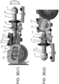
- FIG. 3 D ( 1 ) is a first side view
- FIG. 3 D ( 2 ) is a second side view of the example reciprocating mechanism in a linear mode of operation.
- FIG. 3 E ( 1 ) is a first side view
- FIG. 3 E ( 2 ) is a second side view of the example reciprocating mechanism in an orbital mode of operation.
- FIG. 3 F is a perspective view of the example reciprocating mechanism shown in FIG. 3 A .
- FIG. 4 A is a schematic illustration of operation of the example reciprocating mechanism in a linear mode of operation.
- FIG. 4 B is a schematic illustration of operation of the example reciprocating mechanism in an orbital mode of operation.
Landscapes
- Engineering & Computer Science (AREA)
- Mechanical Engineering (AREA)
- Transmission Devices (AREA)
Abstract
Description
Claims (19)
Priority Applications (3)
| Application Number | Priority Date | Filing Date | Title |
|---|---|---|---|
| US17/654,130 US12343809B2 (en) | 2022-03-09 | 2022-03-09 | Reciprocating tool having orbit function |
| EP23767677.0A EP4489949A1 (en) | 2022-03-09 | 2023-03-09 | Reciprocating tool having orbit function |
| PCT/US2023/064003 WO2023172994A1 (en) | 2022-03-09 | 2023-03-09 | Reciprocating tool having orbit function |
Applications Claiming Priority (1)
| Application Number | Priority Date | Filing Date | Title |
|---|---|---|---|
| US17/654,130 US12343809B2 (en) | 2022-03-09 | 2022-03-09 | Reciprocating tool having orbit function |
Publications (2)
| Publication Number | Publication Date |
|---|---|
| US20230286126A1 US20230286126A1 (en) | 2023-09-14 |
| US12343809B2 true US12343809B2 (en) | 2025-07-01 |
Family
ID=87933058
Family Applications (1)
| Application Number | Title | Priority Date | Filing Date |
|---|---|---|---|
| US17/654,130 Active 2043-09-11 US12343809B2 (en) | 2022-03-09 | 2022-03-09 | Reciprocating tool having orbit function |
Country Status (3)
| Country | Link |
|---|---|
| US (1) | US12343809B2 (en) |
| EP (1) | EP4489949A1 (en) |
| WO (1) | WO2023172994A1 (en) |
Citations (181)
| Publication number | Priority date | Publication date | Assignee | Title |
|---|---|---|---|---|
| US1362628A (en) | 1919-03-15 | 1920-12-21 | Kaunitz Ernest Lewis | Power-hacksaw |
| US1525070A (en) | 1924-07-14 | 1925-02-03 | George B Coleman | Gearing |
| US2240755A (en) | 1937-09-07 | 1941-05-06 | Briggs Martin | Power tool |
| DE803142C (en) | 1949-03-29 | 1951-03-01 | Scintilla Ag | Crank gear |
| US2610524A (en) | 1948-06-23 | 1952-09-16 | Frederick K Maust | Counterbalancing device |
| US2704941A (en) | 1952-04-03 | 1955-03-29 | Black & Decker Mfg Co | Power driven reciprocating tool |
| US2931402A (en) | 1957-03-22 | 1960-04-05 | Walter A Papworth | Power driven reciprocable cutting tool |
| US2949944A (en) | 1958-06-27 | 1960-08-23 | Oster Mfg Co John | Portable hand held saw |
| US2966178A (en) | 1958-02-13 | 1960-12-27 | Porter Co Inc H K | Drive mechanism for power saw |
| US2970484A (en) | 1959-04-20 | 1961-02-07 | Robbins & Myers | Balancing mechanism for sabre saws and the like |
| GB891832A (en) | 1960-04-04 | 1962-03-21 | Black & Decker Mfg Co | Arcuate motion jig saw |
| DE1870185U (en) | 1957-12-03 | 1963-04-11 | Stanley Works | JACK SAW OR JIG SAW. |
| US3095748A (en) | 1961-06-16 | 1963-07-02 | Porter Cable Machine Co | Orbital motion tool |
| US3205721A (en) | 1960-06-13 | 1965-09-14 | Rockwell Mfg Co | Saber saws |
| US3206989A (en) | 1963-05-21 | 1965-09-21 | Black & Decker Mfg Co | Arcuate motion jig saw |
| US3229793A (en) | 1962-08-22 | 1966-01-18 | Sperry Rand Corp | Clutch responsive to predetermined force |
| US3246528A (en) | 1963-04-17 | 1966-04-19 | Alois J Kosch | Rotary-to-reciprocating motion converter |
| US3270369A (en) | 1964-10-02 | 1966-09-06 | Jarvis Corp | Reciprocating saw |
| US3309932A (en) | 1964-06-04 | 1967-03-21 | Portable Electric Tools Inc | Drive mechanism for use in saws and the like |
| US3451276A (en) | 1966-09-20 | 1969-06-24 | F G Miles Eng Ltd | Actuator mechanisms |
| US3457796A (en) | 1966-06-23 | 1969-07-29 | Rockwell Mfg Co | Tool |
| US3461732A (en) | 1966-12-19 | 1969-08-19 | Rockwell Mfg Co | Portable power driven reciprocating saw |
| US3482458A (en) | 1968-07-16 | 1969-12-09 | Black & Decker Mfg Co | Dual stroke length mechanism |
| DE1673054A1 (en) | 1967-12-19 | 1971-08-19 | Sp K Bjuro Analititscheskogo P | Single-beam absorption analyzer for gases, vapors and liquids |
| US3655021A (en) | 1970-11-23 | 1972-04-11 | Froio Corp | Imbalanced braking device |
| US3688522A (en) | 1969-12-29 | 1972-09-05 | Hilti Ag | Overload clutch permitting torque transmission during overload |
| US3729823A (en) | 1971-05-05 | 1973-05-01 | Gardner Denver Co | Reciprocation drive and counterweight arrangement for power saws |
| US3750483A (en) | 1972-04-21 | 1973-08-07 | Stanley Works | Portable reciprocating saw drive mechanism |
| US3766362A (en) | 1972-11-24 | 1973-10-16 | R Pell | Averaging apparatus |
| US3978862A (en) | 1974-08-26 | 1976-09-07 | Stryker Corporation | Surgical cutting device |
| US4145811A (en) | 1977-10-31 | 1979-03-27 | Jarvis Products Corporation | Reciprocating saw |
| GB2042973A (en) | 1979-03-15 | 1980-10-01 | Freund R | Saw |
| FR2451242A1 (en) | 1979-03-14 | 1980-10-10 | Freund Reinhard Maschbau | MACHINE SAW |
| US4385443A (en) | 1981-07-24 | 1983-05-31 | Aeg Power Tool Corporation | Sabre saw |
| US4482042A (en) | 1982-05-17 | 1984-11-13 | Unr Industries, Inc. | Retarder device for moving objects |
| US4542812A (en) | 1984-03-05 | 1985-09-24 | Honeywell Inc. | Variable torque slip clutch |
| US4550501A (en) | 1984-01-23 | 1985-11-05 | Black & Decker Inc. | Orbital-action reciprocating power saw |
| DE3446278A1 (en) | 1984-12-19 | 1986-06-26 | Metabowerke GmbH & Co, 7440 Nürtingen | Jigsaw |
| US4884344A (en) | 1988-08-29 | 1989-12-05 | Robert Bosch Power Tool Corporation | Saber saw |
| DE4009911A1 (en) | 1990-03-28 | 1990-10-31 | Kurt Dipl Ing Spiegelmacher | Cutting soft webs of material - by two=dimensional oscillation of outer blade |
| GB2234034A (en) | 1989-07-11 | 1991-01-23 | Black & Decker Inc | Drive mechanism for converting rotary motion into reciprocating linear motion |
| US5009012A (en) | 1988-08-29 | 1991-04-23 | Robert Bosch Power Tool Corporation | Saber saw |
| US5025562A (en) | 1990-03-01 | 1991-06-25 | Milwaukee Electric Tool Corporation | Counterbalanced reciprocating mechanism |
| US5050307A (en) | 1990-03-01 | 1991-09-24 | Milwaukee Electric Tool Corporation | Wobble plate drive |
| US5099705A (en) | 1989-12-05 | 1992-03-31 | Konstantins Dravnieks | Hand-held reciprocating working tool |
| GB2252072A (en) | 1991-01-23 | 1992-07-29 | Black & Decker Inc | Jigsaw |
| US5134777A (en) | 1991-12-05 | 1992-08-04 | Skil Corporation | Adjustable stroke reciprocating mechanism for a power tool |
| US5205043A (en) * | 1991-01-23 | 1993-04-27 | Black & Decker Inc. | Pendulum jigsaws |
| US5212887A (en) | 1992-03-18 | 1993-05-25 | S-B Power Tool Company | Counterbalanced orbital drive mechanism for saws and the like |
| US5392519A (en) | 1992-09-02 | 1995-02-28 | Makita Corporation | Reciprocating saw |
| USRE35258E (en) | 1990-11-13 | 1996-06-04 | Milwaukee Electric Tool Corporation | Counterbalanced reciprocating mechanism |
| US5561909A (en) | 1995-06-26 | 1996-10-08 | Berg; Donald N. E. | Battery operated saw |
| US5566458A (en) | 1994-12-13 | 1996-10-22 | Milwaukee Electric Tool Corporation | Clutch mechanism for reciprocating saws |
| US5598636A (en) | 1994-08-17 | 1997-02-04 | Ryobi Motor Products | Reciprocating drive saw mechanism |
| US5607023A (en) | 1994-12-13 | 1997-03-04 | Milwaukee Electric Tool Corp. | Impact absorption mechanism for power tools |
| US5653030A (en) | 1994-01-20 | 1997-08-05 | Makita Corporation | Hedge trimmer |
| US5689891A (en) | 1994-12-13 | 1997-11-25 | Milwaukee Electric Tool Corp. | Clutch mechanism for reciprocating saws |
| US5964039A (en) | 1992-07-28 | 1999-10-12 | Matsushita Electric Works, Ltd. | Cutting method and saw tool |
| US6012346A (en) | 1998-09-18 | 2000-01-11 | New Hampshire Ball Bearing, Inc. | Low vibration motion translation system |
| US6209208B1 (en) | 1998-10-09 | 2001-04-03 | Milwaukee Electric Tool Corporarion | Keyless blade clamp mechanism |
| US6212781B1 (en) | 1998-10-09 | 2001-04-10 | Milwaukee Electric Tool Corporation | Reciprocating saw |
| USRE37211E1 (en) | 1994-12-13 | 2001-06-12 | Milwaukee Electric Tool Corporation | Clutch mechanism for reciprocating saws |
| US6249979B1 (en) | 1998-08-13 | 2001-06-26 | Milwaukee Electric Tool Corporation | Orbital reciprocating saw |
| US6260281B1 (en) | 1998-12-24 | 2001-07-17 | Makita Corporation | Blade mounting devices for reciprocating cutting tools |
| US6282797B1 (en) | 1999-03-12 | 2001-09-04 | Hitachi Koki Co., Ltd. | Cutting mechanism for saber saw |
| US6286217B1 (en) | 1998-04-09 | 2001-09-11 | Black & Decker Inc. | Reciprocating saw with pivoted arm drive |
| US6295910B1 (en) | 1999-08-13 | 2001-10-02 | S-B Power Tool Company | Clutch assembly for use with a circular saw |
| US6357125B1 (en) | 2000-04-24 | 2002-03-19 | S-B Power Tool Company | Adjustable stroke mechanism for a scotch yoke assembly |
| USD455328S1 (en) | 2001-08-31 | 2002-04-09 | S-B Power Tool Company | Articulated jigsaw |
| US6370781B1 (en) | 1998-12-04 | 2002-04-16 | Hitachi Koki Co., Ltd. | Reciprocating tool |
| US6508151B1 (en) | 1996-08-19 | 2003-01-21 | Milwaukee Electric Tool Corporation | Reciprocating saw with rocker motion |
| US20030121389A1 (en) | 2002-01-02 | 2003-07-03 | Wheeler Thomas J. | Reciprocating saw |
| US6634107B2 (en) | 1999-03-12 | 2003-10-21 | Hitachi Koki Co., Ltd. | Cutting mechanism for a saber saw |
| US6634437B1 (en) | 1998-04-23 | 2003-10-21 | Gary Rudolph | Apparatus and method for rotary motion conversion and waste product collection unit |
| US6662455B2 (en) | 2001-03-28 | 2003-12-16 | Hitachi Koki Co., Ltd. | Cutting mechanism for a saber saw |
| US6688005B1 (en) | 1999-08-11 | 2004-02-10 | Hitachi Koki Co., Ltd. | Plunger holding device for saber saw |
| US6758119B1 (en) | 1996-08-19 | 2004-07-06 | Milwaukee Electric Tool Corporation | Reciprocating saw with rocker motion |
| US20040194987A1 (en) | 2001-03-07 | 2004-10-07 | Andreas Hanke | Hammer |
| US20040231170A1 (en) | 2000-11-02 | 2004-11-25 | Neitzell Roger Dean | Handle arrangement for a reciprocating saw |
| US20040261273A1 (en) | 2003-06-24 | 2004-12-30 | Griep David B. | Drive mechanism and power tool |
| US20050016001A1 (en) | 2003-06-24 | 2005-01-27 | Milwaukee Electric Tool Corporation | Drive mechanism and power tool |
| US6860886B1 (en) | 1999-08-19 | 2005-03-01 | Hee-Young Lee | Reciprocating surgical tool for use at variable angles and in multiple directions |
| US20050252670A1 (en) | 2004-05-12 | 2005-11-17 | Credo Technology Corporation | Rotary to reciprocating motion conversion attachment for a power rotary hand tool |
| US6976313B2 (en) | 2002-04-15 | 2005-12-20 | International Concepts, Inc. | Battery-powered carving knife having a rechargeable battery pack |
| US20060117581A1 (en) | 2004-12-02 | 2006-06-08 | Makita Corporation | Reciprocating power tool |
| US20060124331A1 (en) | 2002-09-13 | 2006-06-15 | Michael Stirm | Rotary tool |
| WO2006065728A2 (en) | 2004-12-14 | 2006-06-22 | Milwaukee Electric Tool Corporation | Reciprocating saw |
| CN2853254Y (en) | 2005-11-25 | 2007-01-03 | 南京德朔实业有限公司 | Reciprocating saw |
| US20070017684A1 (en) | 2003-03-21 | 2007-01-25 | Micheal Stirm | Vibration reduction apparatus for power tool and power tool incorporating such apparatus |
| US7191847B2 (en) | 2003-12-11 | 2007-03-20 | Hilti Aktiengesellschaft | Drive for a motor-driven hand-held tool |
| US20070074407A1 (en) | 2005-09-30 | 2007-04-05 | Serdynski David P | Tool and method of using same |
| US7216433B2 (en) | 2004-05-06 | 2007-05-15 | Hilti Aktiengesellschaft | Saber saw tool |
| US7225546B2 (en) | 2002-12-19 | 2007-06-05 | Hilti Aktiengesellschaft | Reciprocating power saw with secondary bearing element |
| US20070135803A1 (en) | 2005-09-14 | 2007-06-14 | Amir Belson | Methods and apparatus for performing transluminal and other procedures |
| US7290343B2 (en) | 2002-12-19 | 2007-11-06 | Hilti Aktiengsellschaft | Reciprocating stroke bar bearing |
| US7363713B2 (en) | 2003-06-23 | 2008-04-29 | Makita Corporation | Reciprocating power tool |
| DE102007062869A1 (en) | 2007-02-13 | 2008-08-14 | Robert Bosch Gmbh | Linkage drive device for a reciprocating tool |
| DE102007017408B3 (en) | 2007-04-13 | 2008-08-28 | Festool Gmbh | Hacksaw machine i.e. jigsaw, has mass balancing arrangements that rotate together in opposite directions during operation such that individual balance points of arrangements add to balance point formed by mass balancing device |
| US20080251568A1 (en) | 2007-04-13 | 2008-10-16 | Michael Zemlok | Powered surgical instrument |
| US20080287944A1 (en) | 2001-09-28 | 2008-11-20 | Angiodynamics, Inc. | Tissue ablation apparatus and method |
| US20080289843A1 (en) | 2006-11-10 | 2008-11-27 | Joel Townsan | Electric hand screwdriver with adjustable head |
| US20080308606A1 (en) | 2007-06-18 | 2008-12-18 | Timm Richard W | Surgical stapling and cutting instrument with improved firing system |
| US20090077818A1 (en) * | 2007-09-21 | 2009-03-26 | Black & Decker Inc. | Housing of a cutting tool including blade storage, integral blade guard and motor ventilation pathway |
| JP2009083332A (en) | 2007-09-28 | 2009-04-23 | Hitachi Koki Co Ltd | Portable electric saw |
| JP2009101432A (en) | 2007-10-19 | 2009-05-14 | Hitachi Koki Co Ltd | Portable electric saw |
| US7637018B2 (en) | 2005-09-30 | 2009-12-29 | Positec Power Tools (Suzhou) Co. Ltd. | Power tool |
| DE102008042861A1 (en) | 2008-10-15 | 2010-04-22 | Robert Bosch Gmbh | hand-held jigsaw |
| US7707729B2 (en) | 2007-02-02 | 2010-05-04 | Robert Bosch Gmbh | Drive mechanism for a reciprocating tool |
| US20100162579A1 (en) | 2008-03-07 | 2010-07-01 | Michael Naughton | Reciprocating power tool having a counterbalance device |
| US7818887B2 (en) | 2006-07-07 | 2010-10-26 | Robert Bosch Gmbh | Handheld power tool, in particular handheld power saw |
| US20100320252A1 (en) | 2009-06-19 | 2010-12-23 | Tyco Healthcare Group Lp | Flexible surgical stapler with motor in the head |
| US7886841B2 (en) | 2005-03-18 | 2011-02-15 | Black & Decker Inc. | Power tool torque overload clutch |
| US20110107608A1 (en) | 2009-07-23 | 2011-05-12 | Brian Wattenbach | Reciprocating saw |
| JP2011115912A (en) | 2009-12-04 | 2011-06-16 | Hitachi Koki Co Ltd | Reciprocating tool |
| US20110139475A1 (en) | 2008-07-28 | 2011-06-16 | Wacker Neuson Se | Impact device having an impact mechanism lubricating device |
| US7996996B2 (en) | 2003-08-01 | 2011-08-16 | Makita Corporation | Reciprocating power tool |
| US20110315413A1 (en) | 2010-06-25 | 2011-12-29 | Mako Surgical Corp. | Kit-Of Parts for Multi-Functional Tool, Drive Unit, and Operating Members |
| US20120096721A1 (en) | 2010-10-25 | 2012-04-26 | Sinur Robert A | Reciprocating saw |
| US8201337B2 (en) | 2003-06-25 | 2012-06-19 | Robert Bosch Gmbh | Reciprocating cutting tool with orbital action |
| US8230608B2 (en) | 2008-10-23 | 2012-07-31 | Robert Bosch Gmbh | Progressive force cut path drive mechanism for a reciprocating tool |
| US20120192440A1 (en) | 2011-01-27 | 2012-08-02 | Jerabek Jesse J | Power tool with reciprocating blade |
| US20120261153A1 (en) | 2004-08-27 | 2012-10-18 | Makita Coporation | Power tool |
| US8307910B2 (en) | 2010-04-07 | 2012-11-13 | Robert Bosch Gmbh | Drive mechanism for a reciprocating tool |
| DE102011077259A1 (en) | 2011-06-09 | 2012-12-13 | Robert Bosch Gmbh | Motor-driven handsaw |
| USD674263S1 (en) | 2010-10-15 | 2013-01-15 | Robert Bosch Gmbh | Saw |
| US20130019483A1 (en) | 2011-04-01 | 2013-01-24 | Michael Naughton | Reciprocating saw, such as a jigsaw |
| US20130062090A1 (en) | 2011-03-11 | 2013-03-14 | Stanley D. Winnard | Handheld drive device |
| US8403075B2 (en) | 2007-12-19 | 2013-03-26 | Robert Bosch Gmbh | Wobble drive of a hand-held power tool |
| US8407901B2 (en) | 2008-10-23 | 2013-04-02 | Robert Bosch Gmbh | Drive mechanism for a reciprocating tool |
| US20130199812A1 (en) | 2012-02-04 | 2013-08-08 | Andreas Stihl Ag & Co. Kg | Handheld work apparatus |
| US20130247391A1 (en) | 2012-03-26 | 2013-09-26 | Black & Decker Inc. | Power Tool |
| US8578615B2 (en) * | 2011-09-12 | 2013-11-12 | Black & Decker Inc. | Jigsaw with deployable keel and tiltable shoe |
| DE102012210678A1 (en) | 2012-06-25 | 2014-01-02 | Robert Bosch Gmbh | Hand tool |
| US20140171966A1 (en) | 2007-01-10 | 2014-06-19 | Ethicon Endo-Surgery, Inc. | Surgical instrument with wireless communication between a control unit of a robotic system and remote sensor |
| US8763722B2 (en) | 2008-06-24 | 2014-07-01 | Robert Bosch Gmbh | Power tool having clutch device |
| US8813373B2 (en) | 2007-09-14 | 2014-08-26 | Milwaukee Electric Tool Corporation | Blade clamp mechanism |
| US20140245620A1 (en) | 2013-02-06 | 2014-09-04 | Robert Bosch Gmbh | Portable power tool actuating element for a jigsaw, and jigsaw |
| JP2014525354A (en) | 2011-08-31 | 2014-09-29 | インフュージョン ブランズ インターナショナル インコーポレイテッド | Dual reciprocating saw device and saw blade used therefor |
| US20140299345A1 (en) | 2011-12-30 | 2014-10-09 | Campbell Hausfeld / Scott Fetzer Company | Hand-held tools and components thereof |
| US8905153B2 (en) | 2008-06-24 | 2014-12-09 | Robert Bosch Gmbh | Method for operating a power tool having a clutch device |
| CN104209586A (en) | 2013-05-29 | 2014-12-17 | 博世电动工具(中国)有限公司 | Electric tool |
| CN104416225A (en) | 2013-09-05 | 2015-03-18 | 博世电动工具(中国)有限公司 | Reciprocating saw |
| US20150136433A1 (en) | 2012-05-25 | 2015-05-21 | Robert Bosch Gmbh | Percussion Unit |
| EP2903770A2 (en) | 2012-10-08 | 2015-08-12 | Robert Bosch GmbH | Motor-driven machine tool, in particular hand-held power tool |
| US9132491B2 (en) | 2008-03-07 | 2015-09-15 | Milwaukee Electric Tool Corporation | Portable battery-powered reciprocating saw |
| WO2015145912A1 (en) | 2014-03-27 | 2015-10-01 | 株式会社 マキタ | Electric tool |
| US9156097B2 (en) | 2012-03-20 | 2015-10-13 | Milwaukee Electric Tool Corporation | Reciprocating saw blade clamp |
| WO2015155912A1 (en) | 2014-04-08 | 2015-10-15 | 株式会社 マキタ | Electrically driven tool |
| US20150296719A1 (en) | 2005-09-07 | 2015-10-22 | Black & Decker Inc. | Power tool with magnetic blade coupling |
| US20160151845A1 (en) * | 2013-07-24 | 2016-06-02 | Makita Corporation | Reciprocating electric power tool |
| US9393681B2 (en) | 2012-06-13 | 2016-07-19 | Robert Bosch Gmbh | Transmission device |
| EP3053686A1 (en) | 2013-10-04 | 2016-08-10 | Hitachi Koki Co., Ltd. | Reciprocating tool |
| US9470273B2 (en) | 2011-04-27 | 2016-10-18 | Mekra Lang Gmbh & Co. Kg | Automatically switching clutch for a motor vehicle exterior mirror adjustment means |
| US9561552B2 (en) | 2011-02-09 | 2017-02-07 | Robert Bosch Gmbh | Tool machine with an output spindle that moves back and forth |
| US9573207B2 (en) | 2013-05-09 | 2017-02-21 | Makita Corporation | Reciprocating cutting tool |
| US9700949B2 (en) * | 2013-08-02 | 2017-07-11 | Bosch Power Tools (China) Co. Ltd. | Reciprocating drive mechanism and power tool including the same |
| US9724771B2 (en) | 2011-01-31 | 2017-08-08 | Makita Corporation | Reciprocating power tool |
| US9744605B2 (en) * | 2012-01-16 | 2017-08-29 | Bosch Power Tools (China) Co., Ltd. | Saw blade clamping device |
| US9776263B2 (en) | 2010-07-23 | 2017-10-03 | Milwaukee Electric Tool Corporation | Reciprocating saw |
| US9827623B2 (en) * | 2007-09-21 | 2017-11-28 | Black & Decker Inc. | Control of reciprocation speed and orbital magnitude of a jigsaw with a plurality of material and/or task descriptive icons |
| DE102017115754A1 (en) | 2016-07-22 | 2018-01-25 | Makita Corporation | Tool with float |
| US10144106B2 (en) | 2015-11-02 | 2018-12-04 | Lake Country Manufacturing, Inc. | Adjustable stroke mechanism for random orbital machine |
| US20180370012A1 (en) | 2017-06-26 | 2018-12-27 | Bosch Power Tools (China) Co. Ltd. | Electric Power Tool |
| US20190061081A1 (en) | 2016-01-29 | 2019-02-28 | Hilti Aktiengesellschaft | Portable power tool |
| US10259060B2 (en) | 2015-04-17 | 2019-04-16 | Makita Corporation | Reciprocating tool |
| US20190275597A1 (en) | 2010-07-23 | 2019-09-12 | Milwaukee Electric Tool Corporation | Reciprocating saw |
| WO2019235065A1 (en) | 2018-06-08 | 2019-12-12 | 工機ホールディングス株式会社 | Powered tool |
| US20200009668A1 (en) | 2010-07-23 | 2020-01-09 | Milwaukee Electric Tool Corporation | Reciprocating saw |
| US20200063827A1 (en) | 2018-08-27 | 2020-02-27 | GM Global Technology Operations LLC | In-line balance shaft system for internal combustion engines |
| US20200070265A1 (en) | 2017-05-31 | 2020-03-05 | Bosch Power Tools (China) Co., Ltd. | Power Tool |
| EP3038779B1 (en) | 2013-08-26 | 2020-03-25 | Hilti Aktiengesellschaft | Jigsaw transmission |
| US20200094432A1 (en) | 2017-05-31 | 2020-03-26 | Koki Holdings Co., Ltd. | Reciprocating tool |
| EP3038780B1 (en) | 2013-08-26 | 2020-04-08 | Hilti Aktiengesellschaft | Counterweight device |
| US20200398355A1 (en) | 2019-06-24 | 2020-12-24 | Black & Decker Inc. | Force and moment canceling reciprocating mechanism and power tool having same |
| US20210170509A1 (en) | 2019-12-10 | 2021-06-10 | Milwaukee Electric Tool Corporation | Reciprocating saw |
| US20210213548A1 (en) | 2020-01-14 | 2021-07-15 | Milwaukee Electric Tool Corporation | Reciprocating saw |
| US20220305575A1 (en) * | 2021-03-26 | 2022-09-29 | Makita Corporation | Reciprocating cutting tool |
| US20220371112A1 (en) * | 2021-05-24 | 2022-11-24 | Makita Corporation | Electric work machine |
| US20230356310A1 (en) * | 2022-05-04 | 2023-11-09 | Milwaukee Electric Tool Corporation | Jigsaw |
| US11839964B2 (en) * | 2022-03-09 | 2023-12-12 | Black & Decker Inc. | Counterbalancing mechanism and power tool having same |
| US11958121B2 (en) * | 2022-03-04 | 2024-04-16 | Black & Decker Inc. | Reciprocating tool having orbit function |
-
2022
- 2022-03-09 US US17/654,130 patent/US12343809B2/en active Active
-
2023
- 2023-03-09 WO PCT/US2023/064003 patent/WO2023172994A1/en not_active Ceased
- 2023-03-09 EP EP23767677.0A patent/EP4489949A1/en active Pending
Patent Citations (216)
| Publication number | Priority date | Publication date | Assignee | Title |
|---|---|---|---|---|
| US1362628A (en) | 1919-03-15 | 1920-12-21 | Kaunitz Ernest Lewis | Power-hacksaw |
| US1525070A (en) | 1924-07-14 | 1925-02-03 | George B Coleman | Gearing |
| US2240755A (en) | 1937-09-07 | 1941-05-06 | Briggs Martin | Power tool |
| US2610524A (en) | 1948-06-23 | 1952-09-16 | Frederick K Maust | Counterbalancing device |
| DE803142C (en) | 1949-03-29 | 1951-03-01 | Scintilla Ag | Crank gear |
| US2704941A (en) | 1952-04-03 | 1955-03-29 | Black & Decker Mfg Co | Power driven reciprocating tool |
| US2931402A (en) | 1957-03-22 | 1960-04-05 | Walter A Papworth | Power driven reciprocable cutting tool |
| DE1870185U (en) | 1957-12-03 | 1963-04-11 | Stanley Works | JACK SAW OR JIG SAW. |
| US2966178A (en) | 1958-02-13 | 1960-12-27 | Porter Co Inc H K | Drive mechanism for power saw |
| US2949944A (en) | 1958-06-27 | 1960-08-23 | Oster Mfg Co John | Portable hand held saw |
| US2970484A (en) | 1959-04-20 | 1961-02-07 | Robbins & Myers | Balancing mechanism for sabre saws and the like |
| GB891832A (en) | 1960-04-04 | 1962-03-21 | Black & Decker Mfg Co | Arcuate motion jig saw |
| US3205721A (en) | 1960-06-13 | 1965-09-14 | Rockwell Mfg Co | Saber saws |
| US3095748A (en) | 1961-06-16 | 1963-07-02 | Porter Cable Machine Co | Orbital motion tool |
| US3229793A (en) | 1962-08-22 | 1966-01-18 | Sperry Rand Corp | Clutch responsive to predetermined force |
| US3246528A (en) | 1963-04-17 | 1966-04-19 | Alois J Kosch | Rotary-to-reciprocating motion converter |
| US3206989A (en) | 1963-05-21 | 1965-09-21 | Black & Decker Mfg Co | Arcuate motion jig saw |
| US3309932A (en) | 1964-06-04 | 1967-03-21 | Portable Electric Tools Inc | Drive mechanism for use in saws and the like |
| US3270369A (en) | 1964-10-02 | 1966-09-06 | Jarvis Corp | Reciprocating saw |
| US3457796A (en) | 1966-06-23 | 1969-07-29 | Rockwell Mfg Co | Tool |
| US3451276A (en) | 1966-09-20 | 1969-06-24 | F G Miles Eng Ltd | Actuator mechanisms |
| US3461732A (en) | 1966-12-19 | 1969-08-19 | Rockwell Mfg Co | Portable power driven reciprocating saw |
| DE1673054A1 (en) | 1967-12-19 | 1971-08-19 | Sp K Bjuro Analititscheskogo P | Single-beam absorption analyzer for gases, vapors and liquids |
| US3482458A (en) | 1968-07-16 | 1969-12-09 | Black & Decker Mfg Co | Dual stroke length mechanism |
| US3688522A (en) | 1969-12-29 | 1972-09-05 | Hilti Ag | Overload clutch permitting torque transmission during overload |
| US3655021A (en) | 1970-11-23 | 1972-04-11 | Froio Corp | Imbalanced braking device |
| US3729823A (en) | 1971-05-05 | 1973-05-01 | Gardner Denver Co | Reciprocation drive and counterweight arrangement for power saws |
| US3750483A (en) | 1972-04-21 | 1973-08-07 | Stanley Works | Portable reciprocating saw drive mechanism |
| US3766362A (en) | 1972-11-24 | 1973-10-16 | R Pell | Averaging apparatus |
| US3978862A (en) | 1974-08-26 | 1976-09-07 | Stryker Corporation | Surgical cutting device |
| US4145811A (en) | 1977-10-31 | 1979-03-27 | Jarvis Products Corporation | Reciprocating saw |
| FR2451242A1 (en) | 1979-03-14 | 1980-10-10 | Freund Reinhard Maschbau | MACHINE SAW |
| GB2042973A (en) | 1979-03-15 | 1980-10-01 | Freund R | Saw |
| US4385443A (en) | 1981-07-24 | 1983-05-31 | Aeg Power Tool Corporation | Sabre saw |
| US4482042A (en) | 1982-05-17 | 1984-11-13 | Unr Industries, Inc. | Retarder device for moving objects |
| US4550501A (en) | 1984-01-23 | 1985-11-05 | Black & Decker Inc. | Orbital-action reciprocating power saw |
| US4542812A (en) | 1984-03-05 | 1985-09-24 | Honeywell Inc. | Variable torque slip clutch |
| DE3446278A1 (en) | 1984-12-19 | 1986-06-26 | Metabowerke GmbH & Co, 7440 Nürtingen | Jigsaw |
| US4884344A (en) | 1988-08-29 | 1989-12-05 | Robert Bosch Power Tool Corporation | Saber saw |
| US5009012A (en) | 1988-08-29 | 1991-04-23 | Robert Bosch Power Tool Corporation | Saber saw |
| GB2234034A (en) | 1989-07-11 | 1991-01-23 | Black & Decker Inc | Drive mechanism for converting rotary motion into reciprocating linear motion |
| US5099705A (en) | 1989-12-05 | 1992-03-31 | Konstantins Dravnieks | Hand-held reciprocating working tool |
| US5025562A (en) | 1990-03-01 | 1991-06-25 | Milwaukee Electric Tool Corporation | Counterbalanced reciprocating mechanism |
| US5050307A (en) | 1990-03-01 | 1991-09-24 | Milwaukee Electric Tool Corporation | Wobble plate drive |
| DE4009911A1 (en) | 1990-03-28 | 1990-10-31 | Kurt Dipl Ing Spiegelmacher | Cutting soft webs of material - by two=dimensional oscillation of outer blade |
| USRE35258E (en) | 1990-11-13 | 1996-06-04 | Milwaukee Electric Tool Corporation | Counterbalanced reciprocating mechanism |
| GB2252072A (en) | 1991-01-23 | 1992-07-29 | Black & Decker Inc | Jigsaw |
| US5205043A (en) * | 1991-01-23 | 1993-04-27 | Black & Decker Inc. | Pendulum jigsaws |
| US5134777A (en) | 1991-12-05 | 1992-08-04 | Skil Corporation | Adjustable stroke reciprocating mechanism for a power tool |
| US5212887A (en) | 1992-03-18 | 1993-05-25 | S-B Power Tool Company | Counterbalanced orbital drive mechanism for saws and the like |
| EP0561473B1 (en) | 1992-03-18 | 1998-01-21 | S-B Power Tool Company | Counterbalanced orbital drive mechanism for saws and the like |
| US5964039A (en) | 1992-07-28 | 1999-10-12 | Matsushita Electric Works, Ltd. | Cutting method and saw tool |
| US5392519A (en) | 1992-09-02 | 1995-02-28 | Makita Corporation | Reciprocating saw |
| US5653030A (en) | 1994-01-20 | 1997-08-05 | Makita Corporation | Hedge trimmer |
| US5806191A (en) | 1994-01-20 | 1998-09-15 | Makita Corporation | Hedge trimmer |
| US5598636A (en) | 1994-08-17 | 1997-02-04 | Ryobi Motor Products | Reciprocating drive saw mechanism |
| USRE37211E1 (en) | 1994-12-13 | 2001-06-12 | Milwaukee Electric Tool Corporation | Clutch mechanism for reciprocating saws |
| US5689891A (en) | 1994-12-13 | 1997-11-25 | Milwaukee Electric Tool Corp. | Clutch mechanism for reciprocating saws |
| US5566458A (en) | 1994-12-13 | 1996-10-22 | Milwaukee Electric Tool Corporation | Clutch mechanism for reciprocating saws |
| US5607023A (en) | 1994-12-13 | 1997-03-04 | Milwaukee Electric Tool Corp. | Impact absorption mechanism for power tools |
| USRE38606E1 (en) | 1994-12-13 | 2004-10-05 | Milwaukee Electric Tool Corporation | Clutch mechanism for reciprocating saws |
| USRE37529E1 (en) | 1994-12-13 | 2002-01-29 | Milwaukee Tool Corporation | Clutch mechanism for reciprocating saws |
| US5561909A (en) | 1995-06-26 | 1996-10-08 | Berg; Donald N. E. | Battery operated saw |
| US6829831B1 (en) | 1996-08-19 | 2004-12-14 | Milwaukee Electric Tool Corporation | Reciprocating saw with rocker motion |
| US6758119B1 (en) | 1996-08-19 | 2004-07-06 | Milwaukee Electric Tool Corporation | Reciprocating saw with rocker motion |
| US6508151B1 (en) | 1996-08-19 | 2003-01-21 | Milwaukee Electric Tool Corporation | Reciprocating saw with rocker motion |
| US7127973B2 (en) | 1998-02-09 | 2006-10-31 | Milwaukee Electric Tool Corporation | Reciprocating saw |
| US7448137B2 (en) | 1998-02-09 | 2008-11-11 | Milwaukee Electric Tool Corporation | Reciprocating saw |
| US6286217B1 (en) | 1998-04-09 | 2001-09-11 | Black & Decker Inc. | Reciprocating saw with pivoted arm drive |
| US6634437B1 (en) | 1998-04-23 | 2003-10-21 | Gary Rudolph | Apparatus and method for rotary motion conversion and waste product collection unit |
| US6249979B1 (en) | 1998-08-13 | 2001-06-26 | Milwaukee Electric Tool Corporation | Orbital reciprocating saw |
| US7188425B2 (en) | 1998-08-13 | 2007-03-13 | Milwaukee Electric Tool Corporation | Reciprocating saw |
| US6851193B2 (en) | 1998-08-13 | 2005-02-08 | Milwaukee Electric Tool Corp | Reciprocating saw |
| US6012346A (en) | 1998-09-18 | 2000-01-11 | New Hampshire Ball Bearing, Inc. | Low vibration motion translation system |
| US6209208B1 (en) | 1998-10-09 | 2001-04-03 | Milwaukee Electric Tool Corporarion | Keyless blade clamp mechanism |
| US6212781B1 (en) | 1998-10-09 | 2001-04-10 | Milwaukee Electric Tool Corporation | Reciprocating saw |
| US6742267B2 (en) | 1998-10-09 | 2004-06-01 | Milwaukee Electric Tool Corporation | Reciprocating saw |
| US6370781B1 (en) | 1998-12-04 | 2002-04-16 | Hitachi Koki Co., Ltd. | Reciprocating tool |
| US6260281B1 (en) | 1998-12-24 | 2001-07-17 | Makita Corporation | Blade mounting devices for reciprocating cutting tools |
| US6634107B2 (en) | 1999-03-12 | 2003-10-21 | Hitachi Koki Co., Ltd. | Cutting mechanism for a saber saw |
| US6877235B2 (en) | 1999-03-12 | 2005-04-12 | Hitachi Koki Co., Ltd. | Cutting mechanism for a saber saw |
| US6282797B1 (en) | 1999-03-12 | 2001-09-04 | Hitachi Koki Co., Ltd. | Cutting mechanism for saber saw |
| US6688005B1 (en) | 1999-08-11 | 2004-02-10 | Hitachi Koki Co., Ltd. | Plunger holding device for saber saw |
| US6295910B1 (en) | 1999-08-13 | 2001-10-02 | S-B Power Tool Company | Clutch assembly for use with a circular saw |
| US6860886B1 (en) | 1999-08-19 | 2005-03-01 | Hee-Young Lee | Reciprocating surgical tool for use at variable angles and in multiple directions |
| US6357125B1 (en) | 2000-04-24 | 2002-03-19 | S-B Power Tool Company | Adjustable stroke mechanism for a scotch yoke assembly |
| US20040231170A1 (en) | 2000-11-02 | 2004-11-25 | Neitzell Roger Dean | Handle arrangement for a reciprocating saw |
| US20040194987A1 (en) | 2001-03-07 | 2004-10-07 | Andreas Hanke | Hammer |
| US6662455B2 (en) | 2001-03-28 | 2003-12-16 | Hitachi Koki Co., Ltd. | Cutting mechanism for a saber saw |
| USD455328S1 (en) | 2001-08-31 | 2002-04-09 | S-B Power Tool Company | Articulated jigsaw |
| US20080287944A1 (en) | 2001-09-28 | 2008-11-20 | Angiodynamics, Inc. | Tissue ablation apparatus and method |
| US7506447B2 (en) | 2002-01-02 | 2009-03-24 | Black & Decker Inc. | Reciprocating saw |
| US20030121389A1 (en) | 2002-01-02 | 2003-07-03 | Wheeler Thomas J. | Reciprocating saw |
| US6976313B2 (en) | 2002-04-15 | 2005-12-20 | International Concepts, Inc. | Battery-powered carving knife having a rechargeable battery pack |
| US20060124331A1 (en) | 2002-09-13 | 2006-06-15 | Michael Stirm | Rotary tool |
| US7290343B2 (en) | 2002-12-19 | 2007-11-06 | Hilti Aktiengsellschaft | Reciprocating stroke bar bearing |
| US7225546B2 (en) | 2002-12-19 | 2007-06-05 | Hilti Aktiengesellschaft | Reciprocating power saw with secondary bearing element |
| US20070017684A1 (en) | 2003-03-21 | 2007-01-25 | Micheal Stirm | Vibration reduction apparatus for power tool and power tool incorporating such apparatus |
| EP2119536B1 (en) | 2003-03-21 | 2017-08-23 | Black & Decker Inc. | Power tool incorporating vibration reduction apparatus |
| US7363713B2 (en) | 2003-06-23 | 2008-04-29 | Makita Corporation | Reciprocating power tool |
| US20050016001A1 (en) | 2003-06-24 | 2005-01-27 | Milwaukee Electric Tool Corporation | Drive mechanism and power tool |
| US7793420B2 (en) | 2003-06-24 | 2010-09-14 | Milwaukee Electric Tool Corporation | Drive mechanism and power tool |
| US20040261273A1 (en) | 2003-06-24 | 2004-12-30 | Griep David B. | Drive mechanism and power tool |
| US8201337B2 (en) | 2003-06-25 | 2012-06-19 | Robert Bosch Gmbh | Reciprocating cutting tool with orbital action |
| US8371032B2 (en) | 2003-08-01 | 2013-02-12 | Makita Corporation | Power tool with vibration reducing mechanism |
| US7996996B2 (en) | 2003-08-01 | 2011-08-16 | Makita Corporation | Reciprocating power tool |
| US7191847B2 (en) | 2003-12-11 | 2007-03-20 | Hilti Aktiengesellschaft | Drive for a motor-driven hand-held tool |
| US7216433B2 (en) | 2004-05-06 | 2007-05-15 | Hilti Aktiengesellschaft | Saber saw tool |
| US20050252670A1 (en) | 2004-05-12 | 2005-11-17 | Credo Technology Corporation | Rotary to reciprocating motion conversion attachment for a power rotary hand tool |
| US20120261153A1 (en) | 2004-08-27 | 2012-10-18 | Makita Coporation | Power tool |
| US20060117581A1 (en) | 2004-12-02 | 2006-06-08 | Makita Corporation | Reciprocating power tool |
| WO2006065728A2 (en) | 2004-12-14 | 2006-06-22 | Milwaukee Electric Tool Corporation | Reciprocating saw |
| US7886841B2 (en) | 2005-03-18 | 2011-02-15 | Black & Decker Inc. | Power tool torque overload clutch |
| US20150296719A1 (en) | 2005-09-07 | 2015-10-22 | Black & Decker Inc. | Power tool with magnetic blade coupling |
| US20070135803A1 (en) | 2005-09-14 | 2007-06-14 | Amir Belson | Methods and apparatus for performing transluminal and other procedures |
| DE102006041430B4 (en) | 2005-09-30 | 2015-03-19 | Positec Power Tools (Suzhou) Co., Ltd. | Machine tool with motor drive |
| US20070074407A1 (en) | 2005-09-30 | 2007-04-05 | Serdynski David P | Tool and method of using same |
| US7637018B2 (en) | 2005-09-30 | 2009-12-29 | Positec Power Tools (Suzhou) Co. Ltd. | Power tool |
| CN2853254Y (en) | 2005-11-25 | 2007-01-03 | 南京德朔实业有限公司 | Reciprocating saw |
| US7818887B2 (en) | 2006-07-07 | 2010-10-26 | Robert Bosch Gmbh | Handheld power tool, in particular handheld power saw |
| US20080289843A1 (en) | 2006-11-10 | 2008-11-27 | Joel Townsan | Electric hand screwdriver with adjustable head |
| US20140171966A1 (en) | 2007-01-10 | 2014-06-19 | Ethicon Endo-Surgery, Inc. | Surgical instrument with wireless communication between a control unit of a robotic system and remote sensor |
| US7707729B2 (en) | 2007-02-02 | 2010-05-04 | Robert Bosch Gmbh | Drive mechanism for a reciprocating tool |
| DE102007062869A1 (en) | 2007-02-13 | 2008-08-14 | Robert Bosch Gmbh | Linkage drive device for a reciprocating tool |
| EP1980351A2 (en) | 2007-04-13 | 2008-10-15 | Festool GmbH | Hacksaw machine |
| DE102007017408B3 (en) | 2007-04-13 | 2008-08-28 | Festool Gmbh | Hacksaw machine i.e. jigsaw, has mass balancing arrangements that rotate together in opposite directions during operation such that individual balance points of arrangements add to balance point formed by mass balancing device |
| US20080251568A1 (en) | 2007-04-13 | 2008-10-16 | Michael Zemlok | Powered surgical instrument |
| US20080308606A1 (en) | 2007-06-18 | 2008-12-18 | Timm Richard W | Surgical stapling and cutting instrument with improved firing system |
| US20080308607A1 (en) | 2007-06-18 | 2008-12-18 | Timm Richard W | Surgical stapling and cutting instrument with improved closure system |
| US20080308602A1 (en) | 2007-06-18 | 2008-12-18 | Timm Richard W | Surgical stapling and cutting instruments |
| US8813373B2 (en) | 2007-09-14 | 2014-08-26 | Milwaukee Electric Tool Corporation | Blade clamp mechanism |
| US9827623B2 (en) * | 2007-09-21 | 2017-11-28 | Black & Decker Inc. | Control of reciprocation speed and orbital magnitude of a jigsaw with a plurality of material and/or task descriptive icons |
| US20090077818A1 (en) * | 2007-09-21 | 2009-03-26 | Black & Decker Inc. | Housing of a cutting tool including blade storage, integral blade guard and motor ventilation pathway |
| JP2009083332A (en) | 2007-09-28 | 2009-04-23 | Hitachi Koki Co Ltd | Portable electric saw |
| JP2009101432A (en) | 2007-10-19 | 2009-05-14 | Hitachi Koki Co Ltd | Portable electric saw |
| US8403075B2 (en) | 2007-12-19 | 2013-03-26 | Robert Bosch Gmbh | Wobble drive of a hand-held power tool |
| US9233427B2 (en) | 2008-03-07 | 2016-01-12 | Milwaukee Electric Tool Corporation | Portable battery-powered reciprocating saw |
| US9061411B2 (en) | 2008-03-07 | 2015-06-23 | Milwaukee Electric Tool Corporation | Reciprocating power tool having a counterbalance device |
| US9132491B2 (en) | 2008-03-07 | 2015-09-15 | Milwaukee Electric Tool Corporation | Portable battery-powered reciprocating saw |
| US8407902B2 (en) | 2008-03-07 | 2013-04-02 | Milwaukee Electric Tool Corporation | Reciprocating power tool having a counterbalance device |
| US20100162579A1 (en) | 2008-03-07 | 2010-07-01 | Michael Naughton | Reciprocating power tool having a counterbalance device |
| US8763722B2 (en) | 2008-06-24 | 2014-07-01 | Robert Bosch Gmbh | Power tool having clutch device |
| US8905153B2 (en) | 2008-06-24 | 2014-12-09 | Robert Bosch Gmbh | Method for operating a power tool having a clutch device |
| US20110139475A1 (en) | 2008-07-28 | 2011-06-16 | Wacker Neuson Se | Impact device having an impact mechanism lubricating device |
| DE102008042861A1 (en) | 2008-10-15 | 2010-04-22 | Robert Bosch Gmbh | hand-held jigsaw |
| US8407901B2 (en) | 2008-10-23 | 2013-04-02 | Robert Bosch Gmbh | Drive mechanism for a reciprocating tool |
| US8230608B2 (en) | 2008-10-23 | 2012-07-31 | Robert Bosch Gmbh | Progressive force cut path drive mechanism for a reciprocating tool |
| US20100320252A1 (en) | 2009-06-19 | 2010-12-23 | Tyco Healthcare Group Lp | Flexible surgical stapler with motor in the head |
| US20200030897A1 (en) | 2009-07-23 | 2020-01-30 | Milwaukee Electric Tool Corporation | Reciprocating saw |
| US10464148B2 (en) | 2009-07-23 | 2019-11-05 | Milwaukwee Electric Tool Corporation | Reciprocating saw |
| US20110107608A1 (en) | 2009-07-23 | 2011-05-12 | Brian Wattenbach | Reciprocating saw |
| US20170129026A1 (en) | 2009-07-23 | 2017-05-11 | Milwaukee Electric Tool Corporation | Reciprocating saw |
| US9579735B2 (en) | 2009-07-23 | 2017-02-28 | Milwaukee Electric Tool Corporation | Reciprocating saw |
| JP2011115912A (en) | 2009-12-04 | 2011-06-16 | Hitachi Koki Co Ltd | Reciprocating tool |
| US8307910B2 (en) | 2010-04-07 | 2012-11-13 | Robert Bosch Gmbh | Drive mechanism for a reciprocating tool |
| US20130055576A1 (en) | 2010-04-07 | 2013-03-07 | Robert Bosch Gmbh | Drive Mechanism for a Reciprocating Tool |
| US9272347B2 (en) | 2010-04-07 | 2016-03-01 | Robert Bosch Gmbh | Drive mechanism for a reciprocating tool |
| US20110315413A1 (en) | 2010-06-25 | 2011-12-29 | Mako Surgical Corp. | Kit-Of Parts for Multi-Functional Tool, Drive Unit, and Operating Members |
| US20200009668A1 (en) | 2010-07-23 | 2020-01-09 | Milwaukee Electric Tool Corporation | Reciprocating saw |
| US9776263B2 (en) | 2010-07-23 | 2017-10-03 | Milwaukee Electric Tool Corporation | Reciprocating saw |
| US9956625B2 (en) | 2010-07-23 | 2018-05-01 | Milwaukee Electric Tool Corporation | Reciprocating saw |
| US10300541B2 (en) | 2010-07-23 | 2019-05-28 | Milwaukee Electric Tool Corporation | Reciprocating saw |
| US20190275597A1 (en) | 2010-07-23 | 2019-09-12 | Milwaukee Electric Tool Corporation | Reciprocating saw |
| USD674263S1 (en) | 2010-10-15 | 2013-01-15 | Robert Bosch Gmbh | Saw |
| US20120096721A1 (en) | 2010-10-25 | 2012-04-26 | Sinur Robert A | Reciprocating saw |
| EP2481508B1 (en) | 2011-01-27 | 2016-06-22 | Techtronic Power Tools Technology Limited | Power tool with reciprocating blade |
| US20120192440A1 (en) | 2011-01-27 | 2012-08-02 | Jerabek Jesse J | Power tool with reciprocating blade |
| US9724771B2 (en) | 2011-01-31 | 2017-08-08 | Makita Corporation | Reciprocating power tool |
| US9561552B2 (en) | 2011-02-09 | 2017-02-07 | Robert Bosch Gmbh | Tool machine with an output spindle that moves back and forth |
| US20130062090A1 (en) | 2011-03-11 | 2013-03-14 | Stanley D. Winnard | Handheld drive device |
| US20130019483A1 (en) | 2011-04-01 | 2013-01-24 | Michael Naughton | Reciprocating saw, such as a jigsaw |
| US9470273B2 (en) | 2011-04-27 | 2016-10-18 | Mekra Lang Gmbh & Co. Kg | Automatically switching clutch for a motor vehicle exterior mirror adjustment means |
| DE102011077259A1 (en) | 2011-06-09 | 2012-12-13 | Robert Bosch Gmbh | Motor-driven handsaw |
| JP2014525354A (en) | 2011-08-31 | 2014-09-29 | インフュージョン ブランズ インターナショナル インコーポレイテッド | Dual reciprocating saw device and saw blade used therefor |
| US8578615B2 (en) * | 2011-09-12 | 2013-11-12 | Black & Decker Inc. | Jigsaw with deployable keel and tiltable shoe |
| US20140299345A1 (en) | 2011-12-30 | 2014-10-09 | Campbell Hausfeld / Scott Fetzer Company | Hand-held tools and components thereof |
| US9744605B2 (en) * | 2012-01-16 | 2017-08-29 | Bosch Power Tools (China) Co., Ltd. | Saw blade clamping device |
| US20130199812A1 (en) | 2012-02-04 | 2013-08-08 | Andreas Stihl Ag & Co. Kg | Handheld work apparatus |
| US9156097B2 (en) | 2012-03-20 | 2015-10-13 | Milwaukee Electric Tool Corporation | Reciprocating saw blade clamp |
| US20130247391A1 (en) | 2012-03-26 | 2013-09-26 | Black & Decker Inc. | Power Tool |
| US20150136433A1 (en) | 2012-05-25 | 2015-05-21 | Robert Bosch Gmbh | Percussion Unit |
| US9393681B2 (en) | 2012-06-13 | 2016-07-19 | Robert Bosch Gmbh | Transmission device |
| DE102012210678A1 (en) | 2012-06-25 | 2014-01-02 | Robert Bosch Gmbh | Hand tool |
| EP2903770A2 (en) | 2012-10-08 | 2015-08-12 | Robert Bosch GmbH | Motor-driven machine tool, in particular hand-held power tool |
| US20140245620A1 (en) | 2013-02-06 | 2014-09-04 | Robert Bosch Gmbh | Portable power tool actuating element for a jigsaw, and jigsaw |
| US9573207B2 (en) | 2013-05-09 | 2017-02-21 | Makita Corporation | Reciprocating cutting tool |
| CN104209586A (en) | 2013-05-29 | 2014-12-17 | 博世电动工具(中国)有限公司 | Electric tool |
| US20160151845A1 (en) * | 2013-07-24 | 2016-06-02 | Makita Corporation | Reciprocating electric power tool |
| US9700949B2 (en) * | 2013-08-02 | 2017-07-11 | Bosch Power Tools (China) Co. Ltd. | Reciprocating drive mechanism and power tool including the same |
| EP3038779B1 (en) | 2013-08-26 | 2020-03-25 | Hilti Aktiengesellschaft | Jigsaw transmission |
| EP3038780B1 (en) | 2013-08-26 | 2020-04-08 | Hilti Aktiengesellschaft | Counterweight device |
| CN104416225A (en) | 2013-09-05 | 2015-03-18 | 博世电动工具(中国)有限公司 | Reciprocating saw |
| EP3053686A1 (en) | 2013-10-04 | 2016-08-10 | Hitachi Koki Co., Ltd. | Reciprocating tool |
| US20160243634A1 (en) | 2013-10-04 | 2016-08-25 | Hitachi Koki Co., Ltd. | Reciprocating tool |
| WO2015145912A1 (en) | 2014-03-27 | 2015-10-01 | 株式会社 マキタ | Electric tool |
| WO2015155912A1 (en) | 2014-04-08 | 2015-10-15 | 株式会社 マキタ | Electrically driven tool |
| US10259060B2 (en) | 2015-04-17 | 2019-04-16 | Makita Corporation | Reciprocating tool |
| US10144106B2 (en) | 2015-11-02 | 2018-12-04 | Lake Country Manufacturing, Inc. | Adjustable stroke mechanism for random orbital machine |
| US20190061081A1 (en) | 2016-01-29 | 2019-02-28 | Hilti Aktiengesellschaft | Portable power tool |
| DE102017115754A1 (en) | 2016-07-22 | 2018-01-25 | Makita Corporation | Tool with float |
| US20200070265A1 (en) | 2017-05-31 | 2020-03-05 | Bosch Power Tools (China) Co., Ltd. | Power Tool |
| US20200094432A1 (en) | 2017-05-31 | 2020-03-26 | Koki Holdings Co., Ltd. | Reciprocating tool |
| EP3632603A1 (en) | 2017-05-31 | 2020-04-08 | Koki Holdings Co., Ltd. | Reciprocating tool |
| US20180370012A1 (en) | 2017-06-26 | 2018-12-27 | Bosch Power Tools (China) Co. Ltd. | Electric Power Tool |
| WO2019235065A1 (en) | 2018-06-08 | 2019-12-12 | 工機ホールディングス株式会社 | Powered tool |
| US20200063827A1 (en) | 2018-08-27 | 2020-02-27 | GM Global Technology Operations LLC | In-line balance shaft system for internal combustion engines |
| US20200398355A1 (en) | 2019-06-24 | 2020-12-24 | Black & Decker Inc. | Force and moment canceling reciprocating mechanism and power tool having same |
| US11229963B2 (en) | 2019-06-24 | 2022-01-25 | Black & Decker Inc. | Force and moment canceling reciprocating mechanism and power tool having same |
| US20210170509A1 (en) | 2019-12-10 | 2021-06-10 | Milwaukee Electric Tool Corporation | Reciprocating saw |
| US20210213548A1 (en) | 2020-01-14 | 2021-07-15 | Milwaukee Electric Tool Corporation | Reciprocating saw |
| US20220305575A1 (en) * | 2021-03-26 | 2022-09-29 | Makita Corporation | Reciprocating cutting tool |
| US20220371112A1 (en) * | 2021-05-24 | 2022-11-24 | Makita Corporation | Electric work machine |
| US11958121B2 (en) * | 2022-03-04 | 2024-04-16 | Black & Decker Inc. | Reciprocating tool having orbit function |
| US11839964B2 (en) * | 2022-03-09 | 2023-12-12 | Black & Decker Inc. | Counterbalancing mechanism and power tool having same |
| US20240033892A1 (en) * | 2022-03-09 | 2024-02-01 | Black & Decker Inc. | Counterbalancing mechanism and power tool having same |
| US20230356310A1 (en) * | 2022-05-04 | 2023-11-09 | Milwaukee Electric Tool Corporation | Jigsaw |
Non-Patent Citations (1)
| Title |
|---|
| International Search Report and Written Opinion for PCT Application PCT/US2023/064003, mailed on Aug. 1, 2023, 7 pages. |
Also Published As
| Publication number | Publication date |
|---|---|
| EP4489949A1 (en) | 2025-01-15 |
| WO2023172994A1 (en) | 2023-09-14 |
| US20230286126A1 (en) | 2023-09-14 |
Similar Documents
| Publication | Publication Date | Title |
|---|---|---|
| US4238884A (en) | Orbital jig saw | |
| US4240204A (en) | Jig saw | |
| US5134777A (en) | Adjustable stroke reciprocating mechanism for a power tool | |
| US6357125B1 (en) | Adjustable stroke mechanism for a scotch yoke assembly | |
| US8549762B2 (en) | Linkage drive mechanism for a reciprocating tool | |
| US10300541B2 (en) | Reciprocating saw | |
| US7509744B2 (en) | Mode selection mechanism for power tool and power tool incorporating such mechanism | |
| US20140020918A1 (en) | Hand-Held Tool With Rotary-Oscillatory Drive | |
| US20240408710A1 (en) | Rotary power tool | |
| US12370666B2 (en) | Counterbalancing mechanism and power tool having same | |
| US12377479B2 (en) | Reciprocating saw | |
| US3269197A (en) | Variable motion jig saw | |
| US12343809B2 (en) | Reciprocating tool having orbit function | |
| US11958121B2 (en) | Reciprocating tool having orbit function | |
| CN101284320B (en) | Reciprocating cutting tool | |
| US11554430B2 (en) | Reciprocating tool | |
| WO2019134682A1 (en) | Reciprocating saw | |
| GB2271735A (en) | Reciprocating drive in hand held machine tools | |
| JP3897653B2 (en) | Reciprocating power tool | |
| US12466048B2 (en) | Reciprocating tool having offset spur gear and counterweighting assembly | |
| KR102542762B1 (en) | Air motor and Moving apparatus for cutting machine with the air motor | |
| JP2000288897A (en) | Power tool |
Legal Events
| Date | Code | Title | Description |
|---|---|---|---|
| FEPP | Fee payment procedure |
Free format text: ENTITY STATUS SET TO UNDISCOUNTED (ORIGINAL EVENT CODE: BIG.); ENTITY STATUS OF PATENT OWNER: LARGE ENTITY |
|
| STPP | Information on status: patent application and granting procedure in general |
Free format text: DOCKETED NEW CASE - READY FOR EXAMINATION |
|
| AS | Assignment |
Owner name: BLACK & DECKER INC., CONNECTICUT Free format text: ASSIGNMENT OF ASSIGNORS INTEREST;ASSIGNOR:WANG, YANCHAO;REEL/FRAME:059747/0931 Effective date: 20220316 |
|
| STPP | Information on status: patent application and granting procedure in general |
Free format text: NON FINAL ACTION MAILED |
|
| STPP | Information on status: patent application and granting procedure in general |
Free format text: RESPONSE TO NON-FINAL OFFICE ACTION ENTERED AND FORWARDED TO EXAMINER |
|
| STPP | Information on status: patent application and granting procedure in general |
Free format text: NOTICE OF ALLOWANCE MAILED -- APPLICATION RECEIVED IN OFFICE OF PUBLICATIONS |
|
| STCF | Information on status: patent grant |
Free format text: PATENTED CASE |