US7793420B2 - Drive mechanism and power tool - Google Patents

Drive mechanism and power tool Download PDF

Info

Publication number
US7793420B2
US7793420B2 US12/033,260 US3326008A US7793420B2 US 7793420 B2 US7793420 B2 US 7793420B2 US 3326008 A US3326008 A US 3326008A US 7793420 B2 US7793420 B2 US 7793420B2
Authority
US
United States
Prior art keywords
drive
gear
reciprocating saw
set forth
drive arm
Prior art date
Legal status (The legal status is an assumption and is not a legal conclusion. Google has not performed a legal analysis and makes no representation as to the accuracy of the status listed.)
Expired - Lifetime
Application number
US12/033,260
Other versions
US20080189963A1 (en
Inventor
David B. Griep
Richard H. Jungmann
Roger D. Neitzell
Thomas P. James
Thomas R. Bednar
Troy Charles Thorson
David Paul Serdynski
Current Assignee (The listed assignees may be inaccurate. Google has not performed a legal analysis and makes no representation or warranty as to the accuracy of the list.)
Milwaukee Electric Tool Corp
Original Assignee
Milwaukee Electric Tool Corp
Priority date (The priority date is an assumption and is not a legal conclusion. Google has not performed a legal analysis and makes no representation as to the accuracy of the date listed.)
Filing date
Publication date
Priority claimed from US10/602,210 external-priority patent/US20040261273A1/en
Application filed by Milwaukee Electric Tool Corp filed Critical Milwaukee Electric Tool Corp
Priority to US12/033,260 priority Critical patent/US7793420B2/en
Assigned to MILWAUKEE ELECTRIC TOOL CORPORATION reassignment MILWAUKEE ELECTRIC TOOL CORPORATION ASSIGNMENT OF ASSIGNORS INTEREST (SEE DOCUMENT FOR DETAILS). Assignors: BEDNAR, THOMAS R., GRIEP, DAVID B., JAMES, THOMAS P., NEITZELL, ROGER D., JUNGMANN, RICHARD H., SERDYNSKI, DAVID PAUL, THORSON, TROY CHARLES
Publication of US20080189963A1 publication Critical patent/US20080189963A1/en
Application granted granted Critical
Publication of US7793420B2 publication Critical patent/US7793420B2/en
Anticipated expiration legal-status Critical
Expired - Lifetime legal-status Critical Current

Links

Images

Classifications

    • BPERFORMING OPERATIONS; TRANSPORTING
    • B23MACHINE TOOLS; METAL-WORKING NOT OTHERWISE PROVIDED FOR
    • B23DPLANING; SLOTTING; SHEARING; BROACHING; SAWING; FILING; SCRAPING; LIKE OPERATIONS FOR WORKING METAL BY REMOVING MATERIAL, NOT OTHERWISE PROVIDED FOR
    • B23D61/00Tools for sawing machines or sawing devices; Clamping devices for these tools
    • B23D61/02Circular saw blades
    • B23D61/04Circular saw blades with inserted saw teeth the teeth being individually inserted
    • B23D61/06Circular saw blades with inserted saw teeth the teeth being individually inserted in exchangeable arrangement
    • BPERFORMING OPERATIONS; TRANSPORTING
    • B23MACHINE TOOLS; METAL-WORKING NOT OTHERWISE PROVIDED FOR
    • B23DPLANING; SLOTTING; SHEARING; BROACHING; SAWING; FILING; SCRAPING; LIKE OPERATIONS FOR WORKING METAL BY REMOVING MATERIAL, NOT OTHERWISE PROVIDED FOR
    • B23D51/00Sawing machines or sawing devices working with straight blades, characterised only by constructional features of particular parts; Carrying or attaching means for tools, covered by this subclass, which are connected to a carrier at both ends
    • B23D51/16Sawing machines or sawing devices working with straight blades, characterised only by constructional features of particular parts; Carrying or attaching means for tools, covered by this subclass, which are connected to a carrier at both ends of drives or feed mechanisms for straight tools, e.g. saw blades, or bows
    • BPERFORMING OPERATIONS; TRANSPORTING
    • B25HAND TOOLS; PORTABLE POWER-DRIVEN TOOLS; MANIPULATORS
    • B25DPERCUSSIVE TOOLS
    • B25D11/00Portable percussive tools with electromotor or other motor drive
    • B25D11/06Means for driving the impulse member
    • B25D11/12Means for driving the impulse member comprising a crank mechanism
    • YGENERAL TAGGING OF NEW TECHNOLOGICAL DEVELOPMENTS; GENERAL TAGGING OF CROSS-SECTIONAL TECHNOLOGIES SPANNING OVER SEVERAL SECTIONS OF THE IPC; TECHNICAL SUBJECTS COVERED BY FORMER USPC CROSS-REFERENCE ART COLLECTIONS [XRACs] AND DIGESTS
    • Y10TECHNICAL SUBJECTS COVERED BY FORMER USPC
    • Y10TTECHNICAL SUBJECTS COVERED BY FORMER US CLASSIFICATION
    • Y10T74/00Machine element or mechanism
    • Y10T74/18Mechanical movements
    • Y10T74/18056Rotary to or from reciprocating or oscillating
    • Y10T74/18248Crank and slide
    • YGENERAL TAGGING OF NEW TECHNOLOGICAL DEVELOPMENTS; GENERAL TAGGING OF CROSS-SECTIONAL TECHNOLOGIES SPANNING OVER SEVERAL SECTIONS OF THE IPC; TECHNICAL SUBJECTS COVERED BY FORMER USPC CROSS-REFERENCE ART COLLECTIONS [XRACs] AND DIGESTS
    • Y10TECHNICAL SUBJECTS COVERED BY FORMER USPC
    • Y10TTECHNICAL SUBJECTS COVERED BY FORMER US CLASSIFICATION
    • Y10T83/00Cutting
    • Y10T83/687By tool reciprocable along elongated edge
    • Y10T83/688With dynamic balancing or shock absorbing means

Definitions

  • the present invention relates to drive mechanisms and, more particularly, to a drive mechanism for a power tool.
  • a power tool such as, for example, a reciprocating saw, generally includes a housing supporting a motor, an output member adapted to support a tool element and a drive mechanism to drive the output member.
  • the motor and the drive mechanism operate to reciprocate a spindle and a saw blade supported by the spindle.
  • the saw blade may be pinched or bind in the workpiece or may strike a solid object, preventing the saw blade from reciprocating.
  • the sudden stopping of the tool element or saw blade can damage the spindle, the drive mechanism and/or the motor.
  • the present invention provides, among other things, a drive mechanism, a power tool and a reciprocating saw which substantially alleviates one or more of the above-described and other independent problems with existing drive mechanisms, power tools and reciprocating saws.
  • the present invention provides a drive mechanism generally including structure to allow relative movement of components of the drive mechanism to, for example, absorb an impact on the tool element or on the output member.
  • the present invention provides a drive mechanism generally including an elastic member allowing relative movement of components of the drive mechanism to, for example, absorb an impact.
  • the present invention may provide a drive mechanism for a power tool, the power tool generally including a motor including a drive shaft and an output member adapted to support a tool element.
  • the drive mechanism may generally include a drive assembly engaged with and driven by the drive shaft, and a drive arm drivingly connected between the drive assembly and the output member to transmit driving force from the drive assembly to the output member.
  • the drive arm may be configured to absorb an impact.
  • the drive assembly may include a gear rotatably driven about an axis by the drive shaft and drivingly connected to the drive arm.
  • the drive arm may connect the gear to the output member to convert the rotation of the gear to reciprocation of the output member.
  • the drive assembly may also include a hub selectively driven by the gear and an elastic member positioned between the gear and hub to absorb the impact.
  • the drive arm may have a first portion and a second portion, one of the first portion and the second portion being a flexible portion.
  • the flexible portion may be configured to absorb the impact and includes a flexible member.
  • the drive arm may further include a third portion, and the flexible member is located between the second portion and the third portion.
  • the second and third portions may be interlocked to limit the amount of deflection generated in the arm.
  • the flexible portion may have flexure points to create an area of deformation to absorb the impact.
  • the power tool may be a reciprocating saw, and the drive arm may absorb impact resulting from a blade lock-up.
  • the present invention provides a drive mechanism for a power tool, the power tool generally including a motor including a drive shaft and an output member adapted to support a tool element.
  • the drive mechanism may generally include a gear driven by the drive shaft for rotation about an axis, a hub selectively driven by the gear for rotation about the axis, the hub being movable relative to the gear, the hub driving the output member, and structure positioned between the gear and the hub, the structure selectively transmitting drive force from the gear to the hub and selectively allowing relative movement between the gear and the hub.
  • the drive shaft supports a pinion
  • the gear has an outer periphery defining teeth, the teeth preferably being engaged with and driven by the pinion to rotate the gear about the axis.
  • the hub is rotatable about the axis relative to the gear and may have a drive member offset from the axis and connected to the output member to drivingly connect the hub to the output member.
  • the drive mechanism may further comprise a drive arm connecting the drive member to the output member to convert rotation of the hub to reciprocation of the output member.
  • the structure may include an elastic member.
  • the gear may define a pocket and includes a gear protrusion in the pocket, and a portion of the hub may be supported in the pocket and includes a hub protrusion, the gear protrusion drivingly engaging the hub protrusion.
  • at least a portion of the elastic member may be positioned between the gear protrusion and the hub protrusion.
  • the structure is a slip clutch.
  • the power tool may be a reciprocating saw
  • the output member may be a reciprocatable spindle
  • the tool element may be a saw blade operable to cut a workpiece.
  • the structure may preferably absorb impact resulting from a blade lock-up.
  • the present invention may provide a power tool generally including a housing, a motor supported by the housing and having a drive shaft, an output member supported by the housing and adapted to support a tool element, and a drive mechanism supported by the housing and operable to drive the output member.
  • the drive mechanism may generally include a gear driven by the drive shaft for rotation about an axis, a hub selectively driven by the gear for rotation about the axis, the hub being movable relative to the gear, and structure positioned between the gear and the hub, the structure selectively transmitting drive force from the gear to the hub and selectively allowing relative movement between the gear and the hub.
  • the present invention provides a reciprocating saw generally including a housing, a motor supported by the housing and having a drive shaft, a spindle supported by the housing and adapted to support a saw blade, and a drive mechanism supported by the housing and operable to drive the spindle.
  • the drive mechanism may generally include a gear driven by the drive shaft for rotation about an axis, a hub selectively driven by the gear for rotation about the axis, the hub being movable relative to the gear, and structure to absorb impact positioned between the gear and the hub, the structure selectively transmitting drive force from the gear to the hub and allowing relative movement between the gear and the hub to absorb an impact on the spindle.
  • FIG. 1 is a side partial cross-sectional view of a power tool, such as, for example a reciprocating saw.
  • FIG. 2 is a side partial cross-sectional view of a portion of the drive mechanism shown in FIG. 1 .
  • FIG. 3 is a cross-sectional view taken generally along line 3 - 3 in FIG. 2 .
  • FIG. 4 is a cross-sectional view taken generally along line 4 - 4 in FIG. 2 .
  • FIG. 5 is an exploded perspective view of a portion of the drive mechanism shown in FIG. 1 .
  • FIG. 6 is a plan view of the drive mechanism gear and hub components.
  • FIG. 7 is a side partial cross-sectional view of an alternative construction of a power tool, such as, for example a reciprocating saw.
  • FIG. 8 is a side partial cross-sectional view of another alternative construction of a power tool, such as, for example a reciprocating saw.
  • FIG. 9 is an exploded view of an alternative drive arm according to FIG. 8 .
  • FIG. 10 is a cross-sectional view taken generally along line 10 - 10 of FIG. 8 .
  • FIG. 11 is a cross sectional view taken generally along line 11 - 11 of FIG. 10 .
  • FIG. 12 is a side cross-sectional view of an alternative construction of a power tool, such as, for example a reciprocating saw.
  • FIG. 13 is a top cross-sectional view of the reciprocating saw shown in FIG. 12 , illustrating the slip clutch.
  • FIG. 14 is a partial top view showing the slip clutch of FIG. 13 in greater detail.
  • FIG. 15 is an exploded view of the slip clutch of FIG. 13 .
  • FIG. 16 is a side partial cross-sectional view of an alternative construction of a power tool, such as, for example a reciprocating saw.
  • FIG. 17 is a cross-sectional view taken generally along line 17 - 17 in FIG. 16 .
  • FIG. 18 is a cross-sectional view taken generally along line 18 - 18 in FIG. 16 .
  • FIG. 19 is an exploded perspective view of a portion of the drive mechanism shown in FIG. 16 .
  • FIG. 20 is an exploded perspective view of an alternative construction of a drive mechanism.
  • a power tool such as, for example, a reciprocating saw 10 , and a drive mechanism 12 embodying independent aspects of the invention are illustrated in FIG. 1 .
  • the power tool may be another type of power tool, such as, for example, a hammer, a rotary hammer, a circular saw, a drill, etc., or another type of powered equipment or device, such as, for example, a compressor, an engine, a motor, a pneumatic tool, an appliance, a hydraulic motor, a generator, etc.
  • the reciprocating saw 10 generally includes a housing 14 that supports a motor 16 (partially shown).
  • the motor 16 includes a drive shaft 18 that engages the drive mechanism 12 to drive an output member or spindle 22 .
  • the spindle 22 is supported by the housing 14 for generally reciprocating movement and is adapted to support a tool element, such as a saw blade (not shown). It should be understood that the spindle 22 may be supported and driven to also partially move in a direction transverse to the axis of reciprocation to provide, for example, orbital motion or rocking motion, of the spindle 22 and saw blade.
  • the drive mechanism 12 generally includes a gear 26 , a hub 30 (see FIGS. 2-5 ) and structure, such as an elastic member 34 , at least partially between (in a force-transmitting and/or positional sense) the gear 26 and the hub 30 .
  • the drive shaft 18 drives the gear 26 for rotation about an axis 38 .
  • the gear 26 selectively drives the hub 30 for rotation about axis 38 .
  • the hub 30 is supported for movement, such as, for example, limited pivoting or rotational movement about the axis 38 , relative to the gear 26 .
  • the hub 30 drives the spindle 22 .
  • FIGS. 1 the drive shaft 18 drives the gear 26 for rotation about an axis 38 .
  • the gear 26 selectively drives the hub 30 for rotation about axis 38 .
  • the hub 30 is supported for movement, such as, for example, limited pivoting or rotational movement about the axis 38 , relative to the gear 26 .
  • the hub 30 drives the spindle 22 .
  • the elastic member 34 is positioned at least partially between (in the illustrated construction, in both a force-transmitting and positional sense) the gear 26 and the hub 30 to selectively transmit drive force from the gear 26 to the hub 30 and to selectively allow relative movement between the gear 26 and the hub 30 to, for example, absorb an “impact” on the spindle 22 or saw blade.
  • an “impact” may result from relative movement or forces tending to cause relative movement between components of the drive arrangement (i.e., the motor 16 , the drive mechanism 12 , etc.). Such relative movement may be undesirable and may wear and/or damage the components. For example, an impact may occur if the tool element binds on a workpiece (i.e., a saw blade being pinched by the workpiece) or strikes an obstacle while the drive mechanism 12 and/or the motor 16 continue to apply a drive force. An impact may also occur if the output element is stopped because it strikes an obstacle or due to friction between the spindle 22 and the spindle support while the motor 16 continues to apply driving force. In addition, an impact may occur if the motor 16 is stopped while the inertia of the drive mechanism 12 and/or the driven mechanism (i.e., the output element and/or the tool element) continues movement of these components.
  • the drive shaft 18 supports a pinion 42 .
  • the gear 26 includes an outer periphery 46 defining teeth 50 , and the pinion 42 engages the teeth 50 to rotate the gear 26 about the axis 38 .
  • the hub 30 includes a drive member 54 offset from axis 38 and defining an eccentric axis 56 .
  • a drive arm 58 is connected between the drive member 54 and the spindle 22 and drivingly connects the hub 30 to the spindle 22 to convert rotational movement of the hub 30 into generally reciprocating movement of the spindle 22 .
  • the gear 26 defines a pocket 62 and includes at least one and, in the illustrated construction, four gear protrusions 66 .
  • a portion of the hub 30 is supported in the pocket 62 .
  • the hub 30 includes at least one and, in the illustrated construction, four hub protrusions 70 .
  • the gear protrusion 66 selectively drivingly engages the hub protrusion 70 (through the elastic member 34 ), transmitting driving force from the gear 26 to the hub 30 and causing rotation of the hub 30 with the gear 26 .
  • the gear 26 may not define a pocket 62 , and the hub 30 may not be positioned in such a pocket. In such constructions, the gear 26 and the hub 30 may be positioned in axial face-to-face relation. It should also be understood that, in some aspects and in some constructions (not shown), substantially all of the hub 30 may be positioned in the pocket 62 .
  • the gear protrusions 66 and the hub protrusions 70 are generally the same size and generally equally spaced apart. It should be understood that in some constructions (not shown), the gear protrusions 66 and the hub protrusions 70 may be of different sizes and/or may be spaced apart unequally.
  • the elastic member 34 is positioned between the gear 26 and the hub 30 to selectively transmit driving force from the gear 26 to the hub 30 and to selectively allow relative movement between the gear 26 and the hub 30 to, for example, absorb an impact on the spindle 22 or on the saw blade.
  • the elastic member 34 includes a body and at least one and, in the illustrated construction, eight elastic member protrusions 74 connected to the body.
  • an elastic member protrusion 74 is positioned between each adjacent gear protrusion 66 and hub protrusion 70 .
  • each gear protrusion 66 includes a gear protrusion first side 78 and a gear protrusion second side 82
  • each hub protrusion 70 includes a hub protrusion first side 86 and a hub protrusion second side 90
  • an elastic member protrusion 74 is positioned circumferentially between a gear protrusion first side 78 and a hub protrusion first side 86
  • another elastic member protrusion 74 is positioned circumferentially between a gear protrusion second side 82 and a hub protrusion second side 90 .
  • the elastic member 34 may not include a body but may include separate, independent elastic members (similar to the elastic member protrusions 74 ) between adjacent gear protrusions 66 and hub protrusions 70 .
  • the elastic member protrusions 74 may be connected to a body portion, and the remaining elastic member portions 74 may be connected to another body portion, or may be separate from and independent of a body portion.
  • the elastic member 34 is formed of rubber. In other constructions, the elastic member 34 may be formed of another elastomeric material, such as, for example, silicone, neoprene, nitrile, EPDM, or polymers of various durometer. Also, in other constructions (not shown), the elastic member 34 may have a geometry and/or construction providing the necessary characteristics, such as elasticity, resiliency, etc. (i.e., a cut-out portion).
  • the drive shaft 18 rotates the gear 26 , and the gear 26 rotates the hub 30 (through the elastic member 34 ).
  • Eccentric rotation of the drive member 54 and the resulting motion of the drive arm 58 causes reciprocation of the spindle 22 (and of the saw blade).
  • the elastic member 34 may be initially slightly compressed to a driving force-transmitting condition.
  • the hub 30 may be slowed (relative to the rotational speed of the gear 26 ) or may stop rotating. If the motor 16 continues to operate, the drive shaft 18 continues to rotate the gear 26 . In such a condition, the elastic member 34 allows relative rotational movement between the rotating gear 26 and the slowed or stopped hub 30 .
  • Each elastic member protrusion 74 is compressed to an impact-absorbing condition between each adjacent gear protrusion 66 and hub protrusion 70 .
  • the elastic member 34 thus operates to absorb the impact which may prevent wear or damage to the components of the reciprocating saw 10 (including the drive mechanism 12 and the motor 16 ). After the impact is absorbed, the elastic member 34 returns to its original uncompressed condition or to the slightly compressed driving-force transmitting condition.
  • the elastic member 34 is compressed to absorb an impact
  • the elastic member 34 may be arranged to be in tension, torsion, etc. to absorb the impact.
  • the term “elastic” is a relative term.
  • the elastic member 34 is sufficiently rigid to transmit driving force between the gear 26 and the hub 30 and sufficiently flexible to accommodate some relative movement between the gear 26 and the hub 30 to, for example, absorb an impact.
  • the elastic member 34 is sufficiently resilient to substantially (and, preferably, repeatedly) return to its original shape after operation and after absorbing an impact.
  • the structure between the gear 26 and the hub may include another type of elastic member, such as a spring.
  • a spring may be a compression, tension or torsion spring, formed of, for example, spring steel.
  • the structure may include yet other types of elastic members, such as, for example, air-damped shock absorbers, fluid-damped systems, etc., and/or combinations of elastic members.
  • the structure between the gear 26 and the hub 30 may include flexible and/or flexibly-mounted gear protrusions (not shown) and/or hub protrusions (not shown) on the gear 26 and on the hub 30 , respectively.
  • the gear protrusions and/or the hub protrusions selectively transmit the drive force and selectively allow the relative movement between the gear 26 and the hub 30 .
  • the structure between the gear 26 and the hub 30 may be between the gear 26 and the hub 30 in only a force-transmitting sense.
  • Such structure may be provided by a slip clutch 94 between the gear 26 and the hub 30 (see FIG. 13 ). The details of the slip clutch 94 will be described in detail below with respect to FIGS. 12-15 .
  • the structure between the gear 26 and the hub 30 may include another drive arrangement (not shown) between the gear 26 and the hub 30 .
  • a frictional drive arrangement may be provided between (in both a force-transmitting and positional sense) the gear 26 and the hub 30 , and relative movement of the gear 26 and the hub 30 may occur if a force is applied to overcome this frictional engagement.
  • the structure transmits drive force between the gear 26 and the hub 30 in both directions of rotation about the axis 38 . Also, in the illustrated construction, the structure transmits substantially the same force (i.e., allows relative movement of the gear 26 and the hub 30 at substantially the same opposing force threshold or impact force) in both rotational directions. In other constructions (not shown), the structure may transmit drive force and/or allow relative movement between the gear 26 and the hub 30 in only one rotational direction (i.e., impact absorption provided in only a “forward” drive direction and not in an opposite “reverse” drive direction). In other constructions (not shown), the structure may transmit different forces in the opposite rotational directions (i.e., a different “impact” force required for relative movement of the gear 26 and the hub 30 ).
  • another component of the drive mechanism may be configured to absorb impact.
  • a power tool such as, for example, a reciprocating saw 10 A, including a drive mechanism 12 A with an impact-absorbing drive arm 58 A is illustrated in FIG. 7 .
  • Common elements are identified by the same reference number “A”.
  • the drive mechanism 12 A includes the drive arm 58 A connected between a drive member 54 A and the spindle 22 A.
  • the drive arm 58 A generally includes a first portion 100 and a second portion 104 , and one of the first portion 100 and the second portion 104 (e.g. the first portion 100 ) is a flexible portion.
  • the flexible portion 100 generally includes flexure points 108 formed in the drive arm 58 A that allow for compression and/or movement to absorb impact in the drive mechanism 12 A.
  • the flexure point 108 is a cut-out area of known geometry to allow for a generally known amount of deflection.
  • the flexure point 108 may be provided by a reduced thickness portion of the drive arm 58 A that allows for deflection in the drive arm 58 A.
  • the flexible portion 100 may be provided by a flexure point 108 cut out of the drive arm 58 A which is then filled with a flexible member.
  • the flexible member (not shown) may be formed of a different material than the second portion 104 such as, for example, elastomeric material, rubber, silicone, neoprene, etc.
  • the drive arm 58 A drivingly connects a hub 30 A to the spindle 22 A to convert rotational movement of the hub 30 A into generally reciprocating movement of the spindle 22 A.
  • the drive arm 58 A can be utilized with a gear and hub drive mechanism 12 (as described above for FIGS. 1-6 ), a scotch yoke drive mechanism, a wobble plate drive mechanism, or other drive mechanism.
  • the drive arm 58 A could be used with the construction illustrated in FIGS. 1-6 , or with the construction illustrated in FIGS. 12-14 for greater impact absorption.
  • FIG. 8 illustrates another construction of a power tool, such as, for example, a reciprocating saw 10 B, including a drive mechanism 12 B with an impact-absorbing drive arm 58 B. Common elements are identified by the same reference number “B”.
  • the drive mechanism 12 B generally includes the drive arm 58 B that is configured to absorb impact on the drive mechanism 12 B.
  • the drive arm 58 B includes a first portion 100 B, a second portion 104 B, and a third portion 130 .
  • the first portion 100 B is a flexible member and is located between the second portion 104 B and the third portion 130 .
  • the flexible member 100 B may be insert molded between the second portion 104 B and third portion 130 .
  • the flexible member 100 B is formed of a different material than the second portion 104 B and the third portion 130 such as, for example, elastomeric material, rubber, etc.
  • the second portion 104 B and the third portion 130 are formed of relatively non-flexible material, although it should be understood that the second portion 104 B and/or the third portion 130 may be formed of a relatively flexible material as well.
  • the second portion 104 B and third portion 130 can be interlocking to limit the amount of deflection through the assembly of the drive arm 58 B.
  • the second portion 104 B includes a hook 134 that interacts with a similar hook 138 on the third portion 130 .
  • the first portion 100 B may be molded over the hooks 134 , 138 to provide a flexible member to allow for impact absorption in the drive mechanism 12 B, and the interaction of the hooks 134 , 138 limits the amount of deflection (compression, tension, and/or torsion) in the drive arm 58 B to provide for a relatively stable drive arm 58 B.
  • each hook 134 , 138 includes an aperture 142 , 146 for receiving the end of the opposing hook 138 , 134 thus interlocking the hooks 134 , 138 together.
  • FIGS. 12-15 illustrate another construction of a power tool, such as, for example, a reciprocating saw 10 C, including a drive mechanism 12 C. Common elements are referred to by the same reference number “C”.
  • the drive mechanism 12 C generally includes a gear 26 C, a hub 30 C, and a slip clutch 94 at least partially between the gear 26 C and the hub 30 C.
  • the slip clutch 94 is positioned at least partially between the gear 26 C and the hub 30 C to selectively transmit drive force from the gear 26 C to the hub 30 C and to selectively allow relative movement between the gear 26 C and the hub 30 C to, for example, absorb an impact on the spindle 22 C and/or on the blade (not shown).
  • the gear 26 C drives the hub 30 C, which in turn drives the spindle 22 C.
  • a drive arm 58 C is connected between the drive member 54 C and the spindle 22 C to covert the rotational motion of the hub 30 C into generally reciprocating motion of the spindle 22 C.
  • the drive arm 58 C may be the drive arm 58 as described above with respect to FIGS. 2-5 , the drive arm 58 A as described with respect to FIG. 7 , the drive arm 58 B as described with respect to FIG. 8 , or any other suitable drive arm configuration.
  • FIG. 15 illustrates the slip clutch 94 in more detail.
  • the function of the slip clutch is described in U.S. Pat. No. 5,689,891, issued Nov. 25, 1997 to Bednar, et al., the entire contents of which is incorporated herein by reference.
  • the slip clutch 94 generally includes a plurality of clutch disks 150 , 162 , 170 positioned between the gear 26 C and the hub 30 C.
  • a first clutch disk 150 includes a plurality of radially-outwardly projecting splines 154 that cooperate with corresponding axially-extending grooves 158 on the inner surface of the gear 26 C.
  • a third clutch disk 170 has corresponding radially-outwardly projecting splines 174 that cooperate with the grooves 158 on the gear 26 C.
  • a second clutch disk 162 is sandwiched between the first and third clutch disks 150 , 170 and includes a plurality of radially-inwardly projecting splines 166 that cooperate with corresponding axially-extending grooves (see FIG.
  • the illustrated slip clutch 94 provides four friction surfaces. It should be understood that in other constructions (not shown), the slip clutch 94 may have fewer or more clutch disks or may even include no clutch disks, in which case the slip clutch would comprise the frictional engagement between the gear 26 C and the hub 30 C.
  • the slip clutch 94 also includes a disk spring 178 that biases the clutch disks 150 , 162 , 170 together and then allows slippage if there is binding of the spindle 22 C.
  • the disk spring 178 also controls the frictional engagement between the gear 26 C and the hub 30 C.
  • the clutch 94 will slip when the load on the spindle 22 C (or on the motor 16 C) exceeds the force applied by the disk spring 178 , and the friction between the gear 26 C, hub 30 C, and clutch disks 150 , 162 , 170 . More particularly, the clutch disks 150 , 162 , 170 will slip relative to either or both of the gear 26 C and the hub 30 C to absorb an impact.
  • FIGS. 16-19 illustrate another construction of a power tool, such as, for example, a reciprocating saw, (partially shown) including a drive mechanism 12 D. Common elements are referred to by the same reference number “D”.
  • the drive mechanism 12 D generally includes a gear 26 D, a hub 30 D and structure, such as an elastic member 34 D, at least partially between (in a force-transmitting and/or positional sense) the gear 26 D and the hub 30 D. As shown in FIGS. 16-19 , the elastic member 34 D is positioned in a pocket 62 D defined in the gear 26 D.
  • the elastic member 34 D generally includes a body 35 and at least one and, in the illustrated construction, eight elastic member protrusions 74 D connected to and extending radially outwardly from the body 35 .
  • Each elastic member protrusion 74 D includes a first elastic element 182 and a second elastic element 184 .
  • the first elastic elements 182 are formed of an elastomeric material, such as, for example, rubber, silicone, neoprene, nitrile, EDM, or polymers of various durometer. In the illustrated construction and in some aspects, the first elastic elements 182 are integrally formed with the body 35 of the elastic member 34 D, and both the body 35 and the first elastic elements 182 are formed from a single uniform material.
  • the second elastic elements 184 are integrally formed with the first elastic element 184 .
  • the first elastic elements 182 are formed (e.g., molded) around the second elastic elements 184 .
  • the second elastic elements 184 can be supported in pockets or recesses formed in the second elastic elements 184 .
  • the second elastic elements 184 can be positioned adjacent to and/or spaced between first elastic members 182 .
  • the second elastic elements 184 are coil springs.
  • the second elastic elements 184 can be formed of an elastomeric material, such as, for example, rubber, silicone, neoprene, nitrile, EDM, or polymers of various durometer.
  • the second elastic elements 184 can have a geometery and/or construction providing elasticity and/or resiliency.
  • the elastic member protrusions 74 D are positioned circumferentially between a gear protrusion first side 78 D and a hub protrusion first side 86 D, and another elastic member 74 D is positioned circumferentially between a gear protrusion second side 82 D and a hub protrusion second side 90 D.
  • the gear 26 D rotates the hub 30 D.
  • the engagement between the elastic member protrusions 74 D, the gear protrusions 66 D and the hub protrusions 70 D and the driving force transmitted from the gear 26 D through the elastic member 34 D to the hub 70 D may slightly compress the elastic member protrusions 74 D.
  • the driving force-transmitting condition may slightly compress one or both of the first and second elastic elements 182 , 184 of each of the elastic member protrusions 74 D.
  • Each elastic member protrusion 74 D is also selectively compressed to an impact-absorbing condition between each adjacent gear protrusion 66 D and hub protrusion 70 D to absorb impacts and to prevent wear or damage to the components of the reciprocating saw 10 (including the drive mechanism 12 and the motor 16 ).
  • the second elastic member 184 of each elastic protrusion 74 D absorbs a first range of vibrations and/or impacts and the first elastic member 182 , either alone or in combination with the second elastic member 182 , absorbs a second higher range of vibrations and/or impacts.
  • the second elastic elements 184 are compressed to absorb lower oscillation loads, such as, vibration generated by the drive mechanism 12 D and/or motor 16 and vibration generated by the engagement of the a tool element and the workpiece during normal cutting operations. If the saw blade and/or the spindle 22 is stopped suddenly (e.g., because the saw blade has been pinched or binds in the workpiece or because the saw blade strikes a solid object, preventing the saw blade from reciprocating), the first and second elastic elements 182 , 184 are both compressed to absorb larger impact loads.
  • FIG. 20 illustrates another construction of a power tool, such as, for example, a reciprocating saw (partially shown), including a drive mechanism 12 E. Common elements are referred to by the same reference number “E”.
  • the drive mechanism 12 E generally includes a gear 26 E, a hub 30 E and structure, such as an elastic member 34 E, at least partially between (in a force-transmitting and/or positional sense) the gear 26 E and the hub 30 E.
  • the elastic member 34 E is positioned in a pocket 62 E defined in the gear 26 E.
  • the elastic member 34 E includes a body 35 E and at least one and, in the illustrated construction, six elastic member protrusions 74 E connected to and extending radially outwardly from the body 35 E.
  • Each elastic member protrusion 74 E includes a first elastic element 182 E integrally formed with the body 35 E.
  • the first elastic elements 182 E are formed of an elastomeric material, such as, for example, rubber, silicone, neoprene, nitrile, EDM, or polymers of various durometer. In other constructions (not shown), the first elastic elements 182 E can have a geometery and/or construction providing elasticity and/or resiliency.
  • Second elastic elements 184 E are spaced circumferentially around the pocket 62 E of the gear 26 E between gear protrusions 66 E and the hub protrusions 70 E.
  • the second elastic elements 184 E are coil springs.
  • the second elastic elements 184 E can be formed of an elastomeric material, such as, for example, rubber, silicone, neoprene, nitrile, EDM, or polymers of various durometer.
  • the second elastic elements 184 E can have a geometery and/or construction providing elasticity and/or resiliency.
  • windows or apertures 190 extend axially through the hub 30 E and provide access to the second elastic elements 184 E to facilitate assembly and maintenance of the drive mechanism 12 E.
  • the drive mechanism 12 may be another type of drive mechanism, such as, for example, a rotary-to-rotary motion drive mechanism. It should also be understood that, for some aspects and in some constructions (not shown), the drive mechanism 12 may be used with another driven mechanism in equipment other than power tools, such as, for example, compressors, engines, motors, pneumatic tools, appliances, hydraulic motors, generators, etc.

Abstract

A drive mechanism for a power tool. The power tool includes a motor having a drive shaft and an output member adapted to support a tool element. The drive mechanism includes a drive assembly engaged with and driven by the drive shaft and a drive arm drivingly connected between the drive assembly and the output member to transmit driving force from the drive assembly to the output member. The drive arm is configured to absorb an impact.

Description

RELATED APPLICATIONS
The present application is a divisional of U.S. patent application Ser. No. 10/874,890, filed Jun. 23, 2004, now abandoned, which is a continuation-in-part of U.S. patent application Ser. No. 10/602,210, filed Jun. 24, 2003, the entire contents of both of which are hereby incorporated by reference.
FIELD OF THE INVENTION
The present invention relates to drive mechanisms and, more particularly, to a drive mechanism for a power tool.
SUMMARY OF THE INVENTION
A power tool, such as, for example, a reciprocating saw, generally includes a housing supporting a motor, an output member adapted to support a tool element and a drive mechanism to drive the output member. In the reciprocating saw, the motor and the drive mechanism operate to reciprocate a spindle and a saw blade supported by the spindle.
During operation, as the spindle and saw blade are reciprocated, the saw blade may be pinched or bind in the workpiece or may strike a solid object, preventing the saw blade from reciprocating. The sudden stopping of the tool element or saw blade can damage the spindle, the drive mechanism and/or the motor.
The present invention provides, among other things, a drive mechanism, a power tool and a reciprocating saw which substantially alleviates one or more of the above-described and other independent problems with existing drive mechanisms, power tools and reciprocating saws. In some aspects and in some constructions, the present invention provides a drive mechanism generally including structure to allow relative movement of components of the drive mechanism to, for example, absorb an impact on the tool element or on the output member. In some aspects and in some constructions, the present invention provides a drive mechanism generally including an elastic member allowing relative movement of components of the drive mechanism to, for example, absorb an impact.
More particularly, in some aspects and in some constructions, the present invention may provide a drive mechanism for a power tool, the power tool generally including a motor including a drive shaft and an output member adapted to support a tool element. The drive mechanism may generally include a drive assembly engaged with and driven by the drive shaft, and a drive arm drivingly connected between the drive assembly and the output member to transmit driving force from the drive assembly to the output member. The drive arm may be configured to absorb an impact.
In one construction, the drive assembly may include a gear rotatably driven about an axis by the drive shaft and drivingly connected to the drive arm. In another construction, the drive arm may connect the gear to the output member to convert the rotation of the gear to reciprocation of the output member. In another construction, the drive assembly may also include a hub selectively driven by the gear and an elastic member positioned between the gear and hub to absorb the impact.
In one construction, the drive arm may have a first portion and a second portion, one of the first portion and the second portion being a flexible portion. In another construction, the flexible portion may be configured to absorb the impact and includes a flexible member. In another construction, the drive arm may further include a third portion, and the flexible member is located between the second portion and the third portion. In another construction, the second and third portions may be interlocked to limit the amount of deflection generated in the arm. In another construction, the flexible portion may have flexure points to create an area of deformation to absorb the impact. In another construction, the power tool may be a reciprocating saw, and the drive arm may absorb impact resulting from a blade lock-up.
Also, in some aspects and in some constructions, the present invention provides a drive mechanism for a power tool, the power tool generally including a motor including a drive shaft and an output member adapted to support a tool element. The drive mechanism may generally include a gear driven by the drive shaft for rotation about an axis, a hub selectively driven by the gear for rotation about the axis, the hub being movable relative to the gear, the hub driving the output member, and structure positioned between the gear and the hub, the structure selectively transmitting drive force from the gear to the hub and selectively allowing relative movement between the gear and the hub.
In one construction, the drive shaft supports a pinion, and the gear has an outer periphery defining teeth, the teeth preferably being engaged with and driven by the pinion to rotate the gear about the axis. In another construction, the hub is rotatable about the axis relative to the gear and may have a drive member offset from the axis and connected to the output member to drivingly connect the hub to the output member. In another construction, the drive mechanism may further comprise a drive arm connecting the drive member to the output member to convert rotation of the hub to reciprocation of the output member.
In one construction, the structure may include an elastic member. The gear may define a pocket and includes a gear protrusion in the pocket, and a portion of the hub may be supported in the pocket and includes a hub protrusion, the gear protrusion drivingly engaging the hub protrusion. In one construction, at least a portion of the elastic member may be positioned between the gear protrusion and the hub protrusion. In another construction, the structure is a slip clutch.
In some constructions, the power tool may be a reciprocating saw, the output member may be a reciprocatable spindle, and the tool element may be a saw blade operable to cut a workpiece. In such constructions, the structure may preferably absorb impact resulting from a blade lock-up.
In addition, in some aspects and in some constructions, the present invention may provide a power tool generally including a housing, a motor supported by the housing and having a drive shaft, an output member supported by the housing and adapted to support a tool element, and a drive mechanism supported by the housing and operable to drive the output member. The drive mechanism may generally include a gear driven by the drive shaft for rotation about an axis, a hub selectively driven by the gear for rotation about the axis, the hub being movable relative to the gear, and structure positioned between the gear and the hub, the structure selectively transmitting drive force from the gear to the hub and selectively allowing relative movement between the gear and the hub.
Further, in some aspects and in some constructions, the present invention provides a reciprocating saw generally including a housing, a motor supported by the housing and having a drive shaft, a spindle supported by the housing and adapted to support a saw blade, and a drive mechanism supported by the housing and operable to drive the spindle. The drive mechanism may generally include a gear driven by the drive shaft for rotation about an axis, a hub selectively driven by the gear for rotation about the axis, the hub being movable relative to the gear, and structure to absorb impact positioned between the gear and the hub, the structure selectively transmitting drive force from the gear to the hub and allowing relative movement between the gear and the hub to absorb an impact on the spindle.
Independent features and independent advantages of the present invention will become apparent to those skilled in the art upon review of the following detailed description, claims and drawings.
BRIEF DESCRIPTION OF THE DRAWINGS
FIG. 1 is a side partial cross-sectional view of a power tool, such as, for example a reciprocating saw.
FIG. 2 is a side partial cross-sectional view of a portion of the drive mechanism shown in FIG. 1.
FIG. 3 is a cross-sectional view taken generally along line 3-3 in FIG. 2.
FIG. 4 is a cross-sectional view taken generally along line 4-4 in FIG. 2.
FIG. 5 is an exploded perspective view of a portion of the drive mechanism shown in FIG. 1.
FIG. 6 is a plan view of the drive mechanism gear and hub components.
FIG. 7 is a side partial cross-sectional view of an alternative construction of a power tool, such as, for example a reciprocating saw.
FIG. 8 is a side partial cross-sectional view of another alternative construction of a power tool, such as, for example a reciprocating saw.
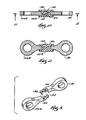
FIG. 9 is an exploded view of an alternative drive arm according to FIG. 8.
FIG. 10 is a cross-sectional view taken generally along line 10-10 of FIG. 8.
FIG. 11 is a cross sectional view taken generally along line 11-11 of FIG. 10.
FIG. 12 is a side cross-sectional view of an alternative construction of a power tool, such as, for example a reciprocating saw.
FIG. 13 is a top cross-sectional view of the reciprocating saw shown in FIG. 12, illustrating the slip clutch.
FIG. 14 is a partial top view showing the slip clutch of FIG. 13 in greater detail.
FIG. 15 is an exploded view of the slip clutch of FIG. 13.
FIG. 16 is a side partial cross-sectional view of an alternative construction of a power tool, such as, for example a reciprocating saw.
FIG. 17 is a cross-sectional view taken generally along line 17-17 in FIG. 16.
FIG. 18 is a cross-sectional view taken generally along line 18-18 in FIG. 16.
FIG. 19 is an exploded perspective view of a portion of the drive mechanism shown in FIG. 16.
FIG. 20 is an exploded perspective view of an alternative construction of a drive mechanism.
Before at least one embodiment of the invention is explained in detail, it is to be understood that the invention is not limited in its application to the details of the construction and the arrangements of the components set forth in the following description or illustrated in the drawings. The invention is capable of other embodiments and of being practiced or carried out in various ways. Also, it is understood that the phraseology and terminology used herein is for the purpose of description and should not be regarded as limiting.
DETAILED DESCRIPTION
A power tool, such as, for example, a reciprocating saw 10, and a drive mechanism 12 embodying independent aspects of the invention are illustrated in FIG. 1. It should be understood that, for some aspects of the invention and in some constructions (not shown), the power tool may be another type of power tool, such as, for example, a hammer, a rotary hammer, a circular saw, a drill, etc., or another type of powered equipment or device, such as, for example, a compressor, an engine, a motor, a pneumatic tool, an appliance, a hydraulic motor, a generator, etc.
As shown in FIG. 1, the reciprocating saw 10 generally includes a housing 14 that supports a motor 16 (partially shown). The motor 16 includes a drive shaft 18 that engages the drive mechanism 12 to drive an output member or spindle 22. In the illustrated construction, the spindle 22 is supported by the housing 14 for generally reciprocating movement and is adapted to support a tool element, such as a saw blade (not shown). It should be understood that the spindle 22 may be supported and driven to also partially move in a direction transverse to the axis of reciprocation to provide, for example, orbital motion or rocking motion, of the spindle 22 and saw blade.
In the illustrated construction and in some aspects, the drive mechanism 12 generally includes a gear 26, a hub 30 (see FIGS. 2-5) and structure, such as an elastic member 34, at least partially between (in a force-transmitting and/or positional sense) the gear 26 and the hub 30. As shown in FIG. 1, the drive shaft 18 drives the gear 26 for rotation about an axis 38. The gear 26 selectively drives the hub 30 for rotation about axis 38. The hub 30 is supported for movement, such as, for example, limited pivoting or rotational movement about the axis 38, relative to the gear 26. As explained below in more detail, the hub 30 drives the spindle 22. As shown in FIGS. 2-5, the elastic member 34 is positioned at least partially between (in the illustrated construction, in both a force-transmitting and positional sense) the gear 26 and the hub 30 to selectively transmit drive force from the gear 26 to the hub 30 and to selectively allow relative movement between the gear 26 and the hub 30 to, for example, absorb an “impact” on the spindle 22 or saw blade.
As used herein, an “impact” may result from relative movement or forces tending to cause relative movement between components of the drive arrangement (i.e., the motor 16, the drive mechanism 12, etc.). Such relative movement may be undesirable and may wear and/or damage the components. For example, an impact may occur if the tool element binds on a workpiece (i.e., a saw blade being pinched by the workpiece) or strikes an obstacle while the drive mechanism 12 and/or the motor 16 continue to apply a drive force. An impact may also occur if the output element is stopped because it strikes an obstacle or due to friction between the spindle 22 and the spindle support while the motor 16 continues to apply driving force. In addition, an impact may occur if the motor 16 is stopped while the inertia of the drive mechanism 12 and/or the driven mechanism (i.e., the output element and/or the tool element) continues movement of these components.
As shown in FIG. 1, the drive shaft 18 supports a pinion 42. The gear 26 includes an outer periphery 46 defining teeth 50, and the pinion 42 engages the teeth 50 to rotate the gear 26 about the axis 38. The hub 30 includes a drive member 54 offset from axis 38 and defining an eccentric axis 56. A drive arm 58 is connected between the drive member 54 and the spindle 22 and drivingly connects the hub 30 to the spindle 22 to convert rotational movement of the hub 30 into generally reciprocating movement of the spindle 22.
A more detailed illustration of the drive mechanism 12 is shown in FIGS. 2-5. In the illustrated construction, the gear 26 defines a pocket 62 and includes at least one and, in the illustrated construction, four gear protrusions 66. In the illustrated construction, a portion of the hub 30 is supported in the pocket 62. The hub 30 includes at least one and, in the illustrated construction, four hub protrusions 70. The gear protrusion 66 selectively drivingly engages the hub protrusion 70 (through the elastic member 34), transmitting driving force from the gear 26 to the hub 30 and causing rotation of the hub 30 with the gear 26.
It should be understood that, in some constructions (not shown), the gear 26 may not define a pocket 62, and the hub 30 may not be positioned in such a pocket. In such constructions, the gear 26 and the hub 30 may be positioned in axial face-to-face relation. It should also be understood that, in some aspects and in some constructions (not shown), substantially all of the hub 30 may be positioned in the pocket 62.
In the illustrated constructions, the gear protrusions 66 and the hub protrusions 70 are generally the same size and generally equally spaced apart. It should be understood that in some constructions (not shown), the gear protrusions 66 and the hub protrusions 70 may be of different sizes and/or may be spaced apart unequally.
At least a portion of the elastic member 34 is positioned between the gear 26 and the hub 30 to selectively transmit driving force from the gear 26 to the hub 30 and to selectively allow relative movement between the gear 26 and the hub 30 to, for example, absorb an impact on the spindle 22 or on the saw blade. In the illustrated construction, the elastic member 34 includes a body and at least one and, in the illustrated construction, eight elastic member protrusions 74 connected to the body. Preferably, an elastic member protrusion 74 is positioned between each adjacent gear protrusion 66 and hub protrusion 70.
As shown in FIG. 6, each gear protrusion 66 includes a gear protrusion first side 78 and a gear protrusion second side 82, and each hub protrusion 70 includes a hub protrusion first side 86 and a hub protrusion second side 90. In the illustrated construction, an elastic member protrusion 74 is positioned circumferentially between a gear protrusion first side 78 and a hub protrusion first side 86, and another elastic member protrusion 74 is positioned circumferentially between a gear protrusion second side 82 and a hub protrusion second side 90.
It should be understood that, in some constructions (not shown), the elastic member 34 may not include a body but may include separate, independent elastic members (similar to the elastic member protrusions 74) between adjacent gear protrusions 66 and hub protrusions 70. In some other constructions (not shown), fewer than all of the elastic member protrusions 74 may be connected to a body portion, and the remaining elastic member portions 74 may be connected to another body portion, or may be separate from and independent of a body portion.
In the illustrated construction, the elastic member 34 is formed of rubber. In other constructions, the elastic member 34 may be formed of another elastomeric material, such as, for example, silicone, neoprene, nitrile, EPDM, or polymers of various durometer. Also, in other constructions (not shown), the elastic member 34 may have a geometry and/or construction providing the necessary characteristics, such as elasticity, resiliency, etc. (i.e., a cut-out portion).
In operation, under normal conditions, when the motor 16 is operated, the drive shaft 18 rotates the gear 26, and the gear 26 rotates the hub 30 (through the elastic member 34). Eccentric rotation of the drive member 54 and the resulting motion of the drive arm 58 causes reciprocation of the spindle 22 (and of the saw blade). At start-up and during operation, the elastic member 34 may be initially slightly compressed to a driving force-transmitting condition.
If the saw blade and/or the spindle 22 is stopped suddenly (i.e., because of an impact), the hub 30 may be slowed (relative to the rotational speed of the gear 26) or may stop rotating. If the motor 16 continues to operate, the drive shaft 18 continues to rotate the gear 26. In such a condition, the elastic member 34 allows relative rotational movement between the rotating gear 26 and the slowed or stopped hub 30. Each elastic member protrusion 74 is compressed to an impact-absorbing condition between each adjacent gear protrusion 66 and hub protrusion 70. The elastic member 34 thus operates to absorb the impact which may prevent wear or damage to the components of the reciprocating saw 10 (including the drive mechanism 12 and the motor 16). After the impact is absorbed, the elastic member 34 returns to its original uncompressed condition or to the slightly compressed driving-force transmitting condition.
While, in the illustrated construction, the elastic member 34 is compressed to absorb an impact, it should be understood that, in other constructions (not shown), the elastic member 34 may be arranged to be in tension, torsion, etc. to absorb the impact.
It should be understood that the term “elastic” is a relative term. In the illustrated construction, the elastic member 34 is sufficiently rigid to transmit driving force between the gear 26 and the hub 30 and sufficiently flexible to accommodate some relative movement between the gear 26 and the hub 30 to, for example, absorb an impact. Also, in the illustrated construction, the elastic member 34 is sufficiently resilient to substantially (and, preferably, repeatedly) return to its original shape after operation and after absorbing an impact.
In other constructions (not shown), the structure between the gear 26 and the hub may include another type of elastic member, such as a spring. Such a spring may be a compression, tension or torsion spring, formed of, for example, spring steel. The structure may include yet other types of elastic members, such as, for example, air-damped shock absorbers, fluid-damped systems, etc., and/or combinations of elastic members.
It should be understood that, in some constructions (not shown), the structure between the gear 26 and the hub 30 may include flexible and/or flexibly-mounted gear protrusions (not shown) and/or hub protrusions (not shown) on the gear 26 and on the hub 30, respectively. In such constructions (not shown), the gear protrusions and/or the hub protrusions selectively transmit the drive force and selectively allow the relative movement between the gear 26 and the hub 30.
It should also be understood that, for some aspects and in some constructions (such as the constructions shown in FIGS. 12-15), the structure between the gear 26 and the hub 30 may be between the gear 26 and the hub 30 in only a force-transmitting sense. Such structure may be provided by a slip clutch 94 between the gear 26 and the hub 30 (see FIG. 13). The details of the slip clutch 94 will be described in detail below with respect to FIGS. 12-15.
In addition, it should be understood that, for some aspects and in some constructions (not shown), the structure between the gear 26 and the hub 30 may include another drive arrangement (not shown) between the gear 26 and the hub 30. For example, a frictional drive arrangement may be provided between (in both a force-transmitting and positional sense) the gear 26 and the hub 30, and relative movement of the gear 26 and the hub 30 may occur if a force is applied to overcome this frictional engagement.
In the construction illustrated in FIGS. 1-6, the structure transmits drive force between the gear 26 and the hub 30 in both directions of rotation about the axis 38. Also, in the illustrated construction, the structure transmits substantially the same force (i.e., allows relative movement of the gear 26 and the hub 30 at substantially the same opposing force threshold or impact force) in both rotational directions. In other constructions (not shown), the structure may transmit drive force and/or allow relative movement between the gear 26 and the hub 30 in only one rotational direction (i.e., impact absorption provided in only a “forward” drive direction and not in an opposite “reverse” drive direction). In other constructions (not shown), the structure may transmit different forces in the opposite rotational directions (i.e., a different “impact” force required for relative movement of the gear 26 and the hub 30).
In other constructions, another component of the drive mechanism may be configured to absorb impact. For example, a power tool, such as, for example, a reciprocating saw 10A, including a drive mechanism 12A with an impact-absorbing drive arm 58A is illustrated in FIG. 7. Common elements are identified by the same reference number “A”.
As shown in FIG. 7, the drive mechanism 12A includes the drive arm 58A connected between a drive member 54A and the spindle 22A. In the illustrated construction, the drive arm 58A generally includes a first portion 100 and a second portion 104, and one of the first portion 100 and the second portion 104 (e.g. the first portion 100) is a flexible portion. In the illustrated construction, the flexible portion 100 generally includes flexure points 108 formed in the drive arm 58A that allow for compression and/or movement to absorb impact in the drive mechanism 12A.
As shown in FIG. 7, the flexure point 108 is a cut-out area of known geometry to allow for a generally known amount of deflection. However, in other constructions (not shown), the flexure point 108 may be provided by a reduced thickness portion of the drive arm 58A that allows for deflection in the drive arm 58A. In yet other constructions (not shown), the flexible portion 100 may be provided by a flexure point 108 cut out of the drive arm 58A which is then filled with a flexible member. In such constructions, the flexible member (not shown) may be formed of a different material than the second portion 104 such as, for example, elastomeric material, rubber, silicone, neoprene, etc.
In the illustrated construction, the drive arm 58A drivingly connects a hub 30A to the spindle 22A to convert rotational movement of the hub 30A into generally reciprocating movement of the spindle 22A. It should be understood that the drive arm 58A can be utilized with a gear and hub drive mechanism 12 (as described above for FIGS. 1-6), a scotch yoke drive mechanism, a wobble plate drive mechanism, or other drive mechanism. Also, it should be understood that the drive arm 58A could be used with the construction illustrated in FIGS. 1-6, or with the construction illustrated in FIGS. 12-14 for greater impact absorption.
FIG. 8 illustrates another construction of a power tool, such as, for example, a reciprocating saw 10B, including a drive mechanism 12B with an impact-absorbing drive arm 58B. Common elements are identified by the same reference number “B”.
As shown in FIG. 8, the drive mechanism 12B generally includes the drive arm 58B that is configured to absorb impact on the drive mechanism 12B. As illustrated, the drive arm 58B includes a first portion 100B, a second portion 104B, and a third portion 130. In the illustrated construction, the first portion 100B is a flexible member and is located between the second portion 104B and the third portion 130. The flexible member 100B may be insert molded between the second portion 104B and third portion 130. As illustrated, the flexible member 100B is formed of a different material than the second portion 104B and the third portion 130 such as, for example, elastomeric material, rubber, etc. By varying the material used to form the flexible member 100B, varying amounts of impact absorption can be achieved within the drive mechanism 12B. Further as illustrated, the second portion 104B and the third portion 130 are formed of relatively non-flexible material, although it should be understood that the second portion 104B and/or the third portion 130 may be formed of a relatively flexible material as well.
As illustrated in FIGS. 9-11, the second portion 104B and third portion 130 can be interlocking to limit the amount of deflection through the assembly of the drive arm 58B. With reference to FIG. 9, the second portion 104B includes a hook 134 that interacts with a similar hook 138 on the third portion 130. The first portion 100B may be molded over the hooks 134, 138 to provide a flexible member to allow for impact absorption in the drive mechanism 12B, and the interaction of the hooks 134, 138 limits the amount of deflection (compression, tension, and/or torsion) in the drive arm 58B to provide for a relatively stable drive arm 58B. As illustrated, each hook 134, 138 includes an aperture 142, 146 for receiving the end of the opposing hook 138, 134 thus interlocking the hooks 134, 138 together.
FIGS. 12-15 illustrate another construction of a power tool, such as, for example, a reciprocating saw 10C, including a drive mechanism 12C. Common elements are referred to by the same reference number “C”.
As shown in FIGS. 12-14, the drive mechanism 12C generally includes a gear 26C, a hub 30C, and a slip clutch 94 at least partially between the gear 26C and the hub 30C. The slip clutch 94 is positioned at least partially between the gear 26C and the hub 30C to selectively transmit drive force from the gear 26C to the hub 30C and to selectively allow relative movement between the gear 26C and the hub 30C to, for example, absorb an impact on the spindle 22C and/or on the blade (not shown). As described above with respect to FIGS. 2-5, the gear 26C drives the hub 30C, which in turn drives the spindle 22C.
In the illustrated construction, a drive arm 58C is connected between the drive member 54C and the spindle 22C to covert the rotational motion of the hub 30C into generally reciprocating motion of the spindle 22C. It is understood that the drive arm 58C may be the drive arm 58 as described above with respect to FIGS. 2-5, the drive arm 58A as described with respect to FIG. 7, the drive arm 58B as described with respect to FIG. 8, or any other suitable drive arm configuration.
FIG. 15 illustrates the slip clutch 94 in more detail. The function of the slip clutch is described in U.S. Pat. No. 5,689,891, issued Nov. 25, 1997 to Bednar, et al., the entire contents of which is incorporated herein by reference.
The slip clutch 94 generally includes a plurality of clutch disks 150, 162, 170 positioned between the gear 26C and the hub 30C. A first clutch disk 150 includes a plurality of radially-outwardly projecting splines 154 that cooperate with corresponding axially-extending grooves 158 on the inner surface of the gear 26C. Similarly, a third clutch disk 170 has corresponding radially-outwardly projecting splines 174 that cooperate with the grooves 158 on the gear 26C. A second clutch disk 162 is sandwiched between the first and third clutch disks 150, 170 and includes a plurality of radially-inwardly projecting splines 166 that cooperate with corresponding axially-extending grooves (see FIG. 14) on the hub 30C. By providing three clutch disks 150, 162, 170, the illustrated slip clutch 94 provides four friction surfaces. It should be understood that in other constructions (not shown), the slip clutch 94 may have fewer or more clutch disks or may even include no clutch disks, in which case the slip clutch would comprise the frictional engagement between the gear 26C and the hub 30C.
The slip clutch 94 also includes a disk spring 178 that biases the clutch disks 150, 162, 170 together and then allows slippage if there is binding of the spindle 22C. The disk spring 178 also controls the frictional engagement between the gear 26C and the hub 30C. The clutch 94 will slip when the load on the spindle 22C (or on the motor 16C) exceeds the force applied by the disk spring 178, and the friction between the gear 26C, hub 30C, and clutch disks 150, 162, 170. More particularly, the clutch disks 150, 162, 170 will slip relative to either or both of the gear 26C and the hub 30C to absorb an impact.
FIGS. 16-19 illustrate another construction of a power tool, such as, for example, a reciprocating saw, (partially shown) including a drive mechanism 12D. Common elements are referred to by the same reference number “D”.
The drive mechanism 12D generally includes a gear 26D, a hub 30D and structure, such as an elastic member 34D, at least partially between (in a force-transmitting and/or positional sense) the gear 26D and the hub 30D. As shown in FIGS. 16-19, the elastic member 34D is positioned in a pocket 62D defined in the gear 26D.
The elastic member 34D generally includes a body 35 and at least one and, in the illustrated construction, eight elastic member protrusions 74D connected to and extending radially outwardly from the body 35. Each elastic member protrusion 74D includes a first elastic element 182 and a second elastic element 184. The first elastic elements 182 are formed of an elastomeric material, such as, for example, rubber, silicone, neoprene, nitrile, EDM, or polymers of various durometer. In the illustrated construction and in some aspects, the first elastic elements 182 are integrally formed with the body 35 of the elastic member 34D, and both the body 35 and the first elastic elements 182 are formed from a single uniform material.
In the construction illustrated in FIGS. 16 and 19, the second elastic elements 184 are integrally formed with the first elastic element 184. Specifically, in the illustrated construction, the first elastic elements 182 are formed (e.g., molded) around the second elastic elements 184. In other constructions (not shown), the second elastic elements 184 can be supported in pockets or recesses formed in the second elastic elements 184. In still other constructions (as shown in FIG. 20), the second elastic elements 184 can be positioned adjacent to and/or spaced between first elastic members 182.
In the illustrated construction, the second elastic elements 184 are coil springs. In other constructions, the second elastic elements 184 can be formed of an elastomeric material, such as, for example, rubber, silicone, neoprene, nitrile, EDM, or polymers of various durometer. In still other constructions (not shown), the second elastic elements 184 can have a geometery and/or construction providing elasticity and/or resiliency.
As shown in FIGS. 16 and 19, the elastic member protrusions 74D are positioned circumferentially between a gear protrusion first side 78D and a hub protrusion first side 86D, and another elastic member 74D is positioned circumferentially between a gear protrusion second side 82D and a hub protrusion second side 90D.
In operation, the gear 26D rotates the hub 30D. At startup and during normal operation, the engagement between the elastic member protrusions 74D, the gear protrusions 66D and the hub protrusions 70D and the driving force transmitted from the gear 26D through the elastic member 34D to the hub 70D may slightly compress the elastic member protrusions 74D. More particularly, the driving force-transmitting condition may slightly compress one or both of the first and second elastic elements 182, 184 of each of the elastic member protrusions 74D.
Each elastic member protrusion 74D is also selectively compressed to an impact-absorbing condition between each adjacent gear protrusion 66D and hub protrusion 70D to absorb impacts and to prevent wear or damage to the components of the reciprocating saw 10 (including the drive mechanism 12 and the motor 16). In the illustrated construction, the second elastic member 184 of each elastic protrusion 74D absorbs a first range of vibrations and/or impacts and the first elastic member 182, either alone or in combination with the second elastic member 182, absorbs a second higher range of vibrations and/or impacts.
For example, in some constructions and in some aspects, the second elastic elements 184 are compressed to absorb lower oscillation loads, such as, vibration generated by the drive mechanism 12D and/or motor 16 and vibration generated by the engagement of the a tool element and the workpiece during normal cutting operations. If the saw blade and/or the spindle 22 is stopped suddenly (e.g., because the saw blade has been pinched or binds in the workpiece or because the saw blade strikes a solid object, preventing the saw blade from reciprocating), the first and second elastic elements 182, 184 are both compressed to absorb larger impact loads.
FIG. 20 illustrates another construction of a power tool, such as, for example, a reciprocating saw (partially shown), including a drive mechanism 12E. Common elements are referred to by the same reference number “E”.
As shown in FIG. 20, the drive mechanism 12E generally includes a gear 26E, a hub 30E and structure, such as an elastic member 34E, at least partially between (in a force-transmitting and/or positional sense) the gear 26E and the hub 30E. The elastic member 34E is positioned in a pocket 62E defined in the gear 26E.
In the illustrated construction, the elastic member 34E includes a body 35E and at least one and, in the illustrated construction, six elastic member protrusions 74E connected to and extending radially outwardly from the body 35E. Each elastic member protrusion 74E includes a first elastic element 182E integrally formed with the body 35E. In the illustrated construction, the first elastic elements 182E are formed of an elastomeric material, such as, for example, rubber, silicone, neoprene, nitrile, EDM, or polymers of various durometer. In other constructions (not shown), the first elastic elements 182E can have a geometery and/or construction providing elasticity and/or resiliency.
Second elastic elements 184E are spaced circumferentially around the pocket 62E of the gear 26E between gear protrusions 66E and the hub protrusions 70E. In the illustrated construction, the second elastic elements 184E are coil springs. In other constructions, the second elastic elements 184E can be formed of an elastomeric material, such as, for example, rubber, silicone, neoprene, nitrile, EDM, or polymers of various durometer. In still other constructions (not shown), the second elastic elements 184E can have a geometery and/or construction providing elasticity and/or resiliency.
In the illustrated construction of FIG. 20, windows or apertures 190 extend axially through the hub 30E and provide access to the second elastic elements 184E to facilitate assembly and maintenance of the drive mechanism 12E.
It should be understood that, for some aspects and in some constructions (not shown), the drive mechanism 12 may be another type of drive mechanism, such as, for example, a rotary-to-rotary motion drive mechanism. It should also be understood that, for some aspects and in some constructions (not shown), the drive mechanism 12 may be used with another driven mechanism in equipment other than power tools, such as, for example, compressors, engines, motors, pneumatic tools, appliances, hydraulic motors, generators, etc.
One or more of the above-identified and other independent features or independent advantages of the invention are set forth in the following claims:

Claims (20)

1. A reciprocating saw comprising:
a motor including a drive shaft;
an output member adapted to support a saw blade; and
a drive mechanism including
a drive assembly engaged with and driven by the drive shaft, and
a drive arm drivingly connected between the drive assembly and the output member to transmit driving force from the drive assembly to the output member, the drive arm including
a first portion pivotably coupled to the drive assembly,
a second portion pivotably coupled to the output member and having a substantially similar shape as the first portion, and
a flexible member interconnecting the first portion and the second portion,
wherein the drive arm is pivotally coupled to the drive assembly and the output member about respective first and second parallel axes, wherein at least a portion of the drive arm is rotatable about a third axis substantially parallel with the first and second axes, and wherein the flexible member is configured to absorb an impact.
2. The reciprocating saw as set forth in claim 1, wherein the drive assembly includes a gear rotatably driven about the third axis by the drive shaft and drivingly connected to the drive arm.
3. The reciprocating saw as set forth in claim 2, wherein the drive assembly includes a drive member supported by the gear and offset from the third axis, the drive member being connected to the drive arm to drivingly connect the gear to the drive arm.
4. The reciprocating saw as set forth in claim 2, wherein the drive arm connects the gear to the output member to convert rotation of the gear to reciprocation of the output member.
5. The reciprocating saw as set forth in claim 2, wherein the drive assembly further includes
a hub selectively driven by the gear, the hub rotatable about the third axis relative to the gear, and
an elastic member positioned between the gear and the hub to absorb the impact.
6. The reciprocating saw set forth in claim 1, wherein the first and second portions of the drive arm are interlocked to limit the amount of deflection of the drive arm.
7. The reciprocating saw set forth in claim 1, wherein the flexible member has a flexure point to create an area of deformation to absorb the impact.
8. The reciprocating saw set forth in claim 7, wherein the flexure point is provided by a cut-out area.
9. The reciprocating saw as set forth in claim 1, wherein the output member is a reciprocatable spindle, and wherein the drive arm absorbs an impact resulting from a blade lock-up.
10. The reciprocating saw set forth in claim 1, wherein the flexible member is formed of a different material than the first portion and the second portion of the drive arm.
11. The reciprocating saw set forth in claim 10, wherein the flexible member is formed of an elastomeric material.
12. The reciprocating saw set forth in claim 10, wherein the flexible member is formed of rubber.
13. A reciprocating saw comprising:
a motor including a drive shaft;
an output member adapted to support a saw blade; and
a drive mechanism including
a drive assembly engaged with and driven by the drive shaft, and
a drive arm drivingly connected between the drive assembly and the output member to transmit driving force from the drive assembly to the output member, the drive arm including
a first portion pivotably coupled to the drive assembly and including a first hook and a first aperture,
a second portion pivotably coupled to the output member and including a second hook and a second aperture, and
a flexible member interconnecting the first portion and the second portion,
wherein the drive arm is pivotally coupled to the drive assembly and the output member about respective first and second parallel axes, wherein at least a portion of the drive arm is rotatable about a third axis substantially parallel with the first and second axes, wherein the flexible member is configured to absorb an impact, wherein the first hook is at least partially received in the second aperture and the second hook is at least partially received in the first aperture, and wherein the flexible member at least partially surrounds the first and second hooks.
14. The reciprocating saw as set forth in claim 13, wherein the drive assembly includes a gear rotatably driven about the third axis by the drive shaft and drivingly connected to the drive arm.
15. The reciprocating saw as set forth in claim 14, wherein the drive assembly includes a drive member supported by the gear and offset from the third axis, the drive member being connected to the drive arm to drivingly connect the gear to the drive arm.
16. The reciprocating saw as set forth in claim 14, wherein the drive arm connects the gear to the output member to convert rotation of the gear to reciprocation of the output member.
17. The reciprocating saw set forth in claim 13, wherein the flexible member is formed of a different material than the first portion and the second portion of the drive arm.
18. The reciprocating saw set forth in claim 17, wherein the flexible member is formed of an elastomeric material.
19. The reciprocating saw set forth in claim 17, wherein the flexible member is formed of rubber.
20. The reciprocating saw set forth in claim 13, wherein the second portion of the drive arm has a substantially similar shape as the first portion of the drive arm.
US12/033,260 2003-06-24 2008-02-19 Drive mechanism and power tool Expired - Lifetime US7793420B2 (en)

Priority Applications (1)

Application Number Priority Date Filing Date Title
US12/033,260 US7793420B2 (en) 2003-06-24 2008-02-19 Drive mechanism and power tool

Applications Claiming Priority (3)

Application Number Priority Date Filing Date Title
US10/602,210 US20040261273A1 (en) 2003-06-24 2003-06-24 Drive mechanism and power tool
US10/874,890 US20050016001A1 (en) 2003-06-24 2004-06-23 Drive mechanism and power tool
US12/033,260 US7793420B2 (en) 2003-06-24 2008-02-19 Drive mechanism and power tool

Related Parent Applications (1)

Application Number Title Priority Date Filing Date
US10/874,890 Division US20050016001A1 (en) 2003-06-24 2004-06-23 Drive mechanism and power tool

Publications (2)

Publication Number Publication Date
US20080189963A1 US20080189963A1 (en) 2008-08-14
US7793420B2 true US7793420B2 (en) 2010-09-14

Family

ID=33519554

Family Applications (2)

Application Number Title Priority Date Filing Date
US10/874,890 Abandoned US20050016001A1 (en) 2003-06-24 2004-06-23 Drive mechanism and power tool
US12/033,260 Expired - Lifetime US7793420B2 (en) 2003-06-24 2008-02-19 Drive mechanism and power tool

Family Applications Before (1)

Application Number Title Priority Date Filing Date
US10/874,890 Abandoned US20050016001A1 (en) 2003-06-24 2004-06-23 Drive mechanism and power tool

Country Status (4)

Country Link
US (2) US20050016001A1 (en)
CN (1) CN1605439A (en)
DE (1) DE102004030580A1 (en)
GB (1) GB2403181B (en)

Cited By (11)

* Cited by examiner, † Cited by third party
Publication number Priority date Publication date Assignee Title
US20090301273A1 (en) * 2008-06-05 2009-12-10 Pro-Cut Licencing Company, Llc On-Vehicle Brake Lathe with Indirect Drive
US20100107427A1 (en) * 2008-10-31 2010-05-06 Hilti Aktiengesellschaft Hand-operated jigsaw
US20100126027A1 (en) * 2008-11-25 2010-05-27 Credo Technology Corporation Impact absorption drive mechanism for a reciprocating tool
US20110107608A1 (en) * 2009-07-23 2011-05-12 Brian Wattenbach Reciprocating saw
US20140322010A1 (en) * 2013-04-29 2014-10-30 Bell Helicopter Textron Inc. Constant-velocity joint link with reduced axial stiffness
US20150065018A1 (en) * 2013-08-30 2015-03-05 Ingersoll-Rand Company Grinders with Friction Drives
US9776263B2 (en) 2010-07-23 2017-10-03 Milwaukee Electric Tool Corporation Reciprocating saw
US10875110B2 (en) 2010-07-23 2020-12-29 Milwaukee Electric Tool Corporation Reciprocating saw
US11052476B2 (en) 2010-07-23 2021-07-06 Milwaukee Electric Tool Corporation Reciprocating saw
US11453093B2 (en) 2019-06-24 2022-09-27 Black & Decker Inc. Reciprocating tool having planetary gear assembly and counterweighting assembly
US11839964B2 (en) 2022-03-09 2023-12-12 Black & Decker Inc. Counterbalancing mechanism and power tool having same

Families Citing this family (16)

* Cited by examiner, † Cited by third party
Publication number Priority date Publication date Assignee Title
CN101489731A (en) * 2006-07-10 2009-07-22 罗伯特·博世有限公司 Hand-held machine tool
US7797841B2 (en) 2006-08-29 2010-09-21 Robert Bosch Gmbh Drive mechanism for a reciprocating saw
US7707729B2 (en) * 2007-02-02 2010-05-04 Robert Bosch Gmbh Drive mechanism for a reciprocating tool
DE102007000393A1 (en) * 2007-07-19 2009-01-22 Hilti Aktiengesellschaft Hand tool with pneumatic percussion
US8006392B2 (en) * 2008-01-31 2011-08-30 Robert Bosch Gmbh Reciprocating tool foot locking arrangement
US20110010951A1 (en) * 2009-07-15 2011-01-20 Ryan Harrison Locking shoe for reciprocating saw
US8230605B2 (en) * 2009-09-15 2012-07-31 Robert Bosch Gmbh Shock absorbing, vibration isolating and jam protecting foot device for a reciprocating saw
JP5811496B2 (en) * 2011-09-15 2015-11-11 日立工機株式会社 Reciprocating tool
US20130133210A1 (en) * 2011-11-30 2013-05-30 Robert Bosch Gmbh Articulating Jig Saw
CN103372683B (en) * 2012-04-27 2017-05-31 博世电动工具(中国)有限公司 For the transmission mechanism of reciprocating saw
US10272506B2 (en) * 2015-12-04 2019-04-30 Nanjing Chervon Industry Co., Ltd. Reciprocating tool with linear guides
JP6989817B2 (en) * 2017-04-05 2022-01-12 ナブテスコ株式会社 Decelerator
CN110142456A (en) * 2018-02-13 2019-08-20 大里兴业有限公司 Pneumatic tool
CN109366539A (en) * 2018-09-26 2019-02-22 李亦然 A kind of electronic dismantling knife of courier packages' carton
CN110508869A (en) * 2019-07-31 2019-11-29 浙江开创电气股份有限公司 Reciprocating saw
CN117358984A (en) * 2022-06-29 2024-01-09 南京泉峰科技有限公司 Power tool

Citations (39)

* Cited by examiner, † Cited by third party
Publication number Priority date Publication date Assignee Title
US110175A (en) * 1870-12-13 Improvement in mechanical movements
US820789A (en) 1905-10-30 1906-05-15 Frederick Hutchins Flexible toothed element.
US1532358A (en) * 1922-11-09 1925-04-07 Weidemann Reinhold Mowing machine
US1697065A (en) 1927-03-18 1929-01-01 Studebaker Corp Elastic-connection regulator
US1780727A (en) 1926-09-29 1930-11-04 Gen Motors Corp Rubber coupler
US2004712A (en) 1930-06-02 1935-06-11 Thiry Leon Elastic shaft coupling
US2560644A (en) 1945-03-14 1951-07-17 Gen Motors Corp Flexible shaft coupling
US2621685A (en) 1949-01-17 1952-12-16 Tri Saw Corp Hand carried power tool
US3071850A (en) 1960-08-18 1963-01-08 Fred L Haushalter Method of making a composite assembly for use between concentric sections of a torsional shaft
US3080897A (en) * 1961-03-31 1963-03-12 Dewalt Inc Saber saw attachment for radial saw machine
FR1380509A (en) 1963-08-29 1964-12-04 Saarlandisches Stahlwerk Dingl Elastic coupling
US3404574A (en) 1966-06-13 1968-10-08 Rockwell Mfg Co Vibration damping mechanism
US3427827A (en) 1966-10-21 1969-02-18 Airheart Prod Shock joint
US3547166A (en) * 1968-07-03 1970-12-15 Singer Co Chuck attachment for sabre saws
US3603173A (en) 1969-11-25 1971-09-07 Bendix Corp Center core for a laminated coupling
US3768334A (en) 1972-06-26 1973-10-30 Bendix Corp Load equalized tension torsion tie bar
US3782220A (en) 1972-05-18 1974-01-01 Bendix Corp Tension-torsion tie bar
US3850255A (en) 1969-08-04 1974-11-26 Rockwell International Corp Power driven hammers or the like
US3859821A (en) 1972-06-22 1975-01-14 Vanmark Corp Flexible coupling
US3945120A (en) 1974-04-25 1976-03-23 Milwaukee Electric Tool Corporation Vibration dampening and heat sink mechanism for a reciprocating power saw
JPS60157516A (en) 1983-12-26 1985-08-17 Keisebun:Kk Flexible coupling
US4552543A (en) 1983-09-14 1985-11-12 Woco Franz-Josef Wolf & Co. Torsionally elastic coupling with an improved characteristic curve
US4569248A (en) 1983-10-18 1986-02-11 Storage Technology Partners Coupling arm for transmitting linear motion
US4648468A (en) 1985-06-26 1987-03-10 Honsa Technologies Portable powered tool with vibration damping
US4764152A (en) 1983-09-27 1988-08-16 Firma Carl Freudenberg Rubber coupling
US5054562A (en) 1990-05-02 1991-10-08 Honsa Ergonomic Technologies, Inc. Vibration-isolated power tool
US5083376A (en) 1988-11-14 1992-01-28 Black & Decker Inc. Thrust bearing arrangement for a power tool transmission
US5127279A (en) 1988-06-22 1992-07-07 Robert Bosch Gmbh Starting device for an internal-combustion engine with start-up shock damping
US5314051A (en) 1992-07-01 1994-05-24 Valeo Friction clutch for a motor vehicle, and an elastic diaphragm for such a clutch
US5564981A (en) 1994-02-10 1996-10-15 Fukoku Co., Ltd. Rotation transmission buffer apparatus
US5607023A (en) 1994-12-13 1997-03-04 Milwaukee Electric Tool Corp. Impact absorption mechanism for power tools
US5689891A (en) 1994-12-13 1997-11-25 Milwaukee Electric Tool Corp. Clutch mechanism for reciprocating saws
US5860218A (en) 1996-10-21 1999-01-19 Vinciguerra; Joseph Synchronized reciprocating saw mechanism
US6044818A (en) 1998-08-26 2000-04-04 Almarv Llc Vibration dampener for internal combustion engines
US6212781B1 (en) * 1998-10-09 2001-04-10 Milwaukee Electric Tool Corporation Reciprocating saw
US6234255B1 (en) 1999-08-12 2001-05-22 S-B Power Tool Company Adjustable stroke for a reciprocating saw
USRE37211E1 (en) 1994-12-13 2001-06-12 Milwaukee Electric Tool Corporation Clutch mechanism for reciprocating saws
US6272971B1 (en) 1997-09-19 2001-08-14 Danfoss Compressors Gmbh Connecting rod for hermetic refrigerating compressor
US6324940B1 (en) 1997-08-13 2001-12-04 Maclean-Fogg Company Composite link

Family Cites Families (102)

* Cited by examiner, † Cited by third party
Publication number Priority date Publication date Assignee Title
US379022A (en) * 1888-03-06 Charles h
US312780A (en) * 1885-02-24 Stephen wilcox
US1222699A (en) * 1917-04-17 James Milton Waugh Spring driving-gear.
US314472A (en) * 1885-03-24 Gear-wheel
US1060865A (en) * 1911-11-16 1913-05-06 August Sundh Combined friction and spur gearing.
US1265811A (en) * 1916-08-22 1918-05-14 Waltham Watch Co Composite machine element.
US1757517A (en) * 1927-10-22 1930-05-06 Brown Lipe Gear Co Vibrationless multiple-disk clutch
US2118913A (en) * 1934-11-24 1938-05-31 Autocar Company Power transmitting mechanism
US2157211A (en) * 1935-12-16 1939-05-09 Harry W Mcdonald Friction clutch
US2187706A (en) * 1936-01-25 1940-01-16 Julien Maurice Franc Alexandre Power transmitting coupling
US2105188A (en) * 1936-06-26 1938-01-11 Guy And Murton Inc Clutch
US2372625A (en) * 1942-11-11 1945-03-27 Wenzel Projector Company Gear
US2400586A (en) * 1944-06-05 1946-05-21 Mercury Clutch Corp Radial pressure clutch
US2460630A (en) * 1945-04-12 1949-02-01 Thomas L Fawick Multicushioned gear
US2591734A (en) * 1949-01-03 1952-04-08 Gen Electric Planetary gear construction
US2869388A (en) * 1953-07-24 1959-01-20 Gen Motors Corp Gear wheels
US2702995A (en) * 1953-12-31 1955-03-01 Goodman Mfg Co Shock absorbing gearing
US3020036A (en) * 1958-02-21 1962-02-06 Gelenkwellenbau Gmbh Rubber spring
US3076352A (en) * 1958-10-13 1963-02-05 Everett P Larsh Gear members and method of producing same
US3078206A (en) * 1959-02-25 1963-02-19 Us Rubber Co Method of forming belt teeth in reinforced positive drive belts
US2939331A (en) * 1959-03-25 1960-06-07 Gen Electric Quiet gear
US3167975A (en) * 1962-05-12 1965-02-02 Francois Durand Device for transmitting motion to a gear
US3229793A (en) * 1962-08-22 1966-01-18 Sperry Rand Corp Clutch responsive to predetermined force
DE1208126B (en) * 1962-08-22 1965-12-30 Pulsgetriebe Erich Friedrich P Single or multiple disk overload slip clutch effective as a vibration damper
US3171270A (en) * 1963-02-25 1965-03-02 Goodman Mfg Co Torque limiting clutch
US3257860A (en) * 1964-06-01 1966-06-28 Burroughs Corp Vibration and shock insulating sprocket
DE1475346B1 (en) * 1965-12-01 1970-05-14 Fichtel & Sachs Ag, 8720 Schweinfurt Clutch disc with several vibration dampers connected in series
US3375911A (en) * 1966-01-03 1968-04-02 Borg Warner Clutch plate employing torsion damper
US3304795A (en) * 1966-02-28 1967-02-21 William S Rouverol Nonlubricated formed gearing
US3362256A (en) * 1966-03-01 1968-01-09 Garrett Corp Combination accessory drive and engine starting mechanism
US3370483A (en) * 1966-03-09 1968-02-27 Bendix Corp Laminated tension-torsion tie-bar
US3360998A (en) * 1966-03-10 1968-01-02 Gen Motors Corp Flexible chain sprocket support
DE1750089A1 (en) * 1968-03-28 1971-01-14 Olympia Werke Ag Gear with internal teeth
US3657813A (en) * 1968-11-29 1972-04-25 Mc Graw Edison Co Powered tree pruning saw
US3557573A (en) * 1968-12-17 1971-01-26 Lohmann & Stolterfoht Ag Highly elastic shaft coupling particularly for use in connection with elastically supported driving engines
US3565223A (en) * 1969-06-09 1971-02-23 Pitts Ind Inc Resilient lining for magnetic clutch
US3640363A (en) * 1969-12-23 1972-02-08 Gen Electric Friction coupling
US3645114A (en) * 1970-05-08 1972-02-29 Shepherd Machinery Co Flexible rotary drive train having splined coupling with elastomeric cushions
US3791499A (en) * 1972-01-03 1974-02-12 J Ryan Clutch
ES420995A1 (en) * 1973-06-29 1976-04-16 Golde Gmbh H T Window regulator, especially for automobiles, with a threaded cable moving in a guide
DE2342401A1 (en) * 1973-08-22 1975-02-27 Renk Ag Zahnraeder GEAR TRANSMISSION
US3885657A (en) * 1973-09-28 1975-05-27 Hisaharu Sato Friction clutch
US3952546A (en) * 1974-08-23 1976-04-27 Kawasaki Jukogyo Kabushiki Kaisha Elastic coupling
US4004669A (en) * 1975-09-02 1977-01-25 Galgon Industries, Inc. Clutch assembly with floater plate and shock canisters
GB1583403A (en) * 1977-07-21 1981-01-28 Automotive Prod Co Ltd Diaphragm spring clutches
US4328879A (en) * 1978-04-27 1982-05-11 The Gates Rubber Company Shock-absorbing sprocket, drive assembly, and the like
FR2486181A1 (en) * 1980-07-02 1982-01-08 Valeo DIAPHRAGM CLUTCH MECHANISM, IN PARTICULAR FOR A MOTOR VEHICLE
GB2124563B (en) * 1982-05-31 1986-01-02 Komatsu Mfg Co Ltd Sprocket wheel assembly of endless track-type vehicles
DE3227004A1 (en) * 1982-07-20 1984-01-26 Fichtel & Sachs Ag, 8720 Schweinfurt CLUTCH DISC WITH FRICTION DAMPER AND LEAF SPRINGS
JPS5924538U (en) * 1982-08-09 1984-02-15 サンデン株式会社 electromagnetic clutch
JPS5972321U (en) * 1982-11-08 1984-05-16 トヨタ自動車株式会社 clutch disc
IT1153392B (en) * 1982-12-10 1987-01-14 Rovilmec Spa CLUTCH DISC PARTICULARLY FOR MOTOR VEHICLES
JPS59103934U (en) * 1982-12-28 1984-07-12 株式会社大金製作所 clutch disk
FR2546592B1 (en) * 1983-05-24 1986-04-11 Valeo CLUTCH MECHANISM
US4638684A (en) * 1983-10-24 1987-01-27 Luk Lamellen Und Kupplungsbau Gmbh Assembly for taking up and compensating for torque-induced shocks
JPS60179523A (en) * 1983-11-10 1985-09-13 ル−ク・ラメレン・ウント・クツプルングスバウ・ゲゼルシヤフト・ミツト・ベシユレンクテル・ハフツング Torque transmitting apparatus
DE3340896A1 (en) * 1983-11-11 1985-05-23 Fichtel & Sachs Ag, 8720 Schweinfurt Torsional vibration damper with play-free storage and defined friction
JPS60113856A (en) * 1983-11-26 1985-06-20 Nippon Denso Co Ltd Power transmission gear
JPS60146922A (en) * 1984-01-06 1985-08-02 Daikin Mfg Co Ltd Torsional damper disk
DE3427163A1 (en) * 1984-07-24 1986-04-03 LuK Lamellen und Kupplungsbau GmbH, 7580 Bühl DEVICE FOR COMPENSATING TURNOVER
DE3628774A1 (en) * 1985-09-07 1987-04-23 Luk Lamellen & Kupplungsbau Device for damping torsional vibrations
EP0227208A1 (en) * 1985-10-29 1987-07-01 Automotive Products Public Limited Company Diaphragm spring clutch cover assembly
GB2184514B (en) * 1985-12-13 1989-10-18 Daikin Mfg Co Ltd Clutch
US4796728A (en) * 1986-05-05 1989-01-10 Austoft Inc. (U.S.A.) Brake noise reduction system
FR2614079B1 (en) * 1987-04-14 1992-04-10 Valeo STRAIGHT MEASUREMENT OF TORSIONAL DAMPING DEVICE
FR2614080B1 (en) * 1987-04-14 1992-04-10 Valeo TORSION DAMPING DEVICE WITH CENTERING BEARING
US4874074A (en) * 1987-08-20 1989-10-17 Eaton Corporation Torsional vibration damping mechanism
JPH01145429A (en) * 1987-11-30 1989-06-07 Aisin Seiki Co Ltd Clutch disk
FR2625772B1 (en) * 1988-01-13 1990-05-25 Valeo ASSEMBLY OF TWO GLOBALLY ANNULAR PARTS, PARTICULARLY DIAPHRAGM AND MOUNTING PART FOR CLUTCH MECHANISM, PARTICULARLY FOR MOTOR VEHICLE
JPH0640996Y2 (en) * 1988-04-11 1994-10-26 株式会社大金製作所 Split flywheel assembly
US4891033A (en) * 1988-04-20 1990-01-02 Automatic Spring Coiling Co. Device for coupling coil springs compressed in series in a clutch damper
DE3937957A1 (en) * 1988-12-15 1990-06-21 Voith Gmbh J M ELASTIC COUPLING
JPH02109024U (en) * 1989-02-17 1990-08-30
SE464930B (en) * 1989-09-20 1991-07-01 Volvo Ab FLY WHEELS FOR COMBUSTION ENGINES
FR2662760B1 (en) * 1990-05-31 1996-06-07 Luk Lamellen & Kupplungsbau TORQUE TRANSMISSION DEVICE.
US5289737A (en) * 1990-08-25 1994-03-01 J. M. Voith Gmbh Elastic clutch
DE4028616C2 (en) * 1990-09-08 2002-09-12 Zf Sachs Ag Clutch disc with identical guide parts to control the coil springs for the idle range
DE4031762B4 (en) * 1990-10-06 2004-09-30 Zf Sachs Ag Clutch disc with space-saving idle damper
US5182519A (en) * 1990-10-22 1993-01-26 Mitsubishi Denki Kabushiki Kaisha Heater control device for an air-fuel ratio sensor
JP3052212B2 (en) * 1991-02-05 2000-06-12 アイシン精機株式会社 Clutch disc
US5113713A (en) * 1991-02-11 1992-05-19 United Technologies Corporation Elastomeric load sharing device
DE4107126A1 (en) * 1991-03-06 1992-09-10 Fichtel & Sachs Ag CLUTCH DISC WITH PLASTIC DAMPER UNIT
JP2979689B2 (en) * 1991-03-30 1999-11-15 アイシン精機株式会社 Torque fluctuation absorber
JP2938219B2 (en) * 1991-05-29 1999-08-23 株式会社ユニシアジェックス Power transmission for automatic transmission
FR2683011B1 (en) * 1991-10-25 1993-12-10 Valeo TORSION DAMPING DEVICE FOR TORQUE TRANSMISSION APPARATUS.
US5209330A (en) * 1991-12-23 1993-05-11 Ford Motor Company Slipping bypass clutch for hydrokinetic torque converter
US5195625A (en) * 1992-05-29 1993-03-23 General Motors Corporation Torque cushion for electromagnetic clutch
US5308282A (en) * 1992-07-15 1994-05-03 Ford Motor Company Pressure plate for a vibration damper assembly having built in lash
US5209370A (en) * 1992-07-16 1993-05-11 Pickett Ralph E Lap tray
US5310025A (en) * 1992-07-23 1994-05-10 Allied-Signal Inc. Aircraft brake vibration damper
US5307705A (en) * 1993-02-09 1994-05-03 Fenelon Paul J Stress dissipation gear and method of making same
US5615746A (en) * 1996-02-02 1997-04-01 Chu; George Reinforced pneumatic tool holder
DE19717624A1 (en) * 1996-05-17 1997-11-20 Mitsuba Corp Reduction transmission with impact absorption mechanism
US6389753B1 (en) * 1996-12-09 2002-05-21 Paul J. Fenelon Window lift mechanism
US5896934A (en) * 1997-09-08 1999-04-27 Chicago Pneumatic Tool Company Reciprocating tool having a piston retainer
US6183368B1 (en) * 1997-10-09 2001-02-06 Ntn Corporation One-way over-running flex coupling
JP4043567B2 (en) * 1997-11-04 2008-02-06 株式会社マキタ Impact tool
JP4040753B2 (en) * 1998-06-03 2008-01-30 アスモ株式会社 Motor and opening / closing member driving device
US6216394B1 (en) * 1998-09-21 2001-04-17 Paul J. Fenelon Window lift mechanism
JP2000225517A (en) * 1998-12-04 2000-08-15 Hitachi Koki Co Ltd Reciprocating tool
US6357125B1 (en) * 2000-04-24 2002-03-19 S-B Power Tool Company Adjustable stroke mechanism for a scotch yoke assembly
JP2003145446A (en) * 2001-11-09 2003-05-20 Yamada Kikai Kogyo Kk Engine breaker

Patent Citations (40)

* Cited by examiner, † Cited by third party
Publication number Priority date Publication date Assignee Title
US110175A (en) * 1870-12-13 Improvement in mechanical movements
US820789A (en) 1905-10-30 1906-05-15 Frederick Hutchins Flexible toothed element.
US1532358A (en) * 1922-11-09 1925-04-07 Weidemann Reinhold Mowing machine
US1780727A (en) 1926-09-29 1930-11-04 Gen Motors Corp Rubber coupler
US1697065A (en) 1927-03-18 1929-01-01 Studebaker Corp Elastic-connection regulator
US2004712A (en) 1930-06-02 1935-06-11 Thiry Leon Elastic shaft coupling
US2560644A (en) 1945-03-14 1951-07-17 Gen Motors Corp Flexible shaft coupling
US2621685A (en) 1949-01-17 1952-12-16 Tri Saw Corp Hand carried power tool
US3071850A (en) 1960-08-18 1963-01-08 Fred L Haushalter Method of making a composite assembly for use between concentric sections of a torsional shaft
US3080897A (en) * 1961-03-31 1963-03-12 Dewalt Inc Saber saw attachment for radial saw machine
FR1380509A (en) 1963-08-29 1964-12-04 Saarlandisches Stahlwerk Dingl Elastic coupling
US3404574A (en) 1966-06-13 1968-10-08 Rockwell Mfg Co Vibration damping mechanism
US3427827A (en) 1966-10-21 1969-02-18 Airheart Prod Shock joint
US3547166A (en) * 1968-07-03 1970-12-15 Singer Co Chuck attachment for sabre saws
US3850255A (en) 1969-08-04 1974-11-26 Rockwell International Corp Power driven hammers or the like
US3603173A (en) 1969-11-25 1971-09-07 Bendix Corp Center core for a laminated coupling
US3782220A (en) 1972-05-18 1974-01-01 Bendix Corp Tension-torsion tie bar
US3859821A (en) 1972-06-22 1975-01-14 Vanmark Corp Flexible coupling
US3768334A (en) 1972-06-26 1973-10-30 Bendix Corp Load equalized tension torsion tie bar
US3945120A (en) 1974-04-25 1976-03-23 Milwaukee Electric Tool Corporation Vibration dampening and heat sink mechanism for a reciprocating power saw
US4552543A (en) 1983-09-14 1985-11-12 Woco Franz-Josef Wolf & Co. Torsionally elastic coupling with an improved characteristic curve
US4764152A (en) 1983-09-27 1988-08-16 Firma Carl Freudenberg Rubber coupling
US4569248A (en) 1983-10-18 1986-02-11 Storage Technology Partners Coupling arm for transmitting linear motion
JPS60157516A (en) 1983-12-26 1985-08-17 Keisebun:Kk Flexible coupling
US4648468A (en) 1985-06-26 1987-03-10 Honsa Technologies Portable powered tool with vibration damping
US5127279A (en) 1988-06-22 1992-07-07 Robert Bosch Gmbh Starting device for an internal-combustion engine with start-up shock damping
US5083376A (en) 1988-11-14 1992-01-28 Black & Decker Inc. Thrust bearing arrangement for a power tool transmission
US5054562A (en) 1990-05-02 1991-10-08 Honsa Ergonomic Technologies, Inc. Vibration-isolated power tool
US5314051A (en) 1992-07-01 1994-05-24 Valeo Friction clutch for a motor vehicle, and an elastic diaphragm for such a clutch
US5564981A (en) 1994-02-10 1996-10-15 Fukoku Co., Ltd. Rotation transmission buffer apparatus
USRE37211E1 (en) 1994-12-13 2001-06-12 Milwaukee Electric Tool Corporation Clutch mechanism for reciprocating saws
US5689891A (en) 1994-12-13 1997-11-25 Milwaukee Electric Tool Corp. Clutch mechanism for reciprocating saws
US5607023A (en) 1994-12-13 1997-03-04 Milwaukee Electric Tool Corp. Impact absorption mechanism for power tools
USRE37529E1 (en) 1994-12-13 2002-01-29 Milwaukee Tool Corporation Clutch mechanism for reciprocating saws
US5860218A (en) 1996-10-21 1999-01-19 Vinciguerra; Joseph Synchronized reciprocating saw mechanism
US6324940B1 (en) 1997-08-13 2001-12-04 Maclean-Fogg Company Composite link
US6272971B1 (en) 1997-09-19 2001-08-14 Danfoss Compressors Gmbh Connecting rod for hermetic refrigerating compressor
US6044818A (en) 1998-08-26 2000-04-04 Almarv Llc Vibration dampener for internal combustion engines
US6212781B1 (en) * 1998-10-09 2001-04-10 Milwaukee Electric Tool Corporation Reciprocating saw
US6234255B1 (en) 1999-08-12 2001-05-22 S-B Power Tool Company Adjustable stroke for a reciprocating saw

Cited By (24)

* Cited by examiner, † Cited by third party
Publication number Priority date Publication date Assignee Title
US8215212B2 (en) * 2008-06-05 2012-07-10 Pro-Cut Licensing Company, Llc On-vehicle brake lathe with indirect drive
US20090301273A1 (en) * 2008-06-05 2009-12-10 Pro-Cut Licencing Company, Llc On-Vehicle Brake Lathe with Indirect Drive
US20100107427A1 (en) * 2008-10-31 2010-05-06 Hilti Aktiengesellschaft Hand-operated jigsaw
US8640347B2 (en) * 2008-10-31 2014-02-04 Hilti Aktiengesellschaft Hand-operated jigsaw
US20100126027A1 (en) * 2008-11-25 2010-05-27 Credo Technology Corporation Impact absorption drive mechanism for a reciprocating tool
US8826547B2 (en) * 2008-11-25 2014-09-09 Robert Bosch Gmbh Impact absorption drive mechanism for a reciprocating tool
US9579735B2 (en) * 2009-07-23 2017-02-28 Milwaukee Electric Tool Corporation Reciprocating saw
US20110107608A1 (en) * 2009-07-23 2011-05-12 Brian Wattenbach Reciprocating saw
US11919097B2 (en) 2009-07-23 2024-03-05 Milwaukee Electric Tool Corporation Reciprocating saw
US10464148B2 (en) 2009-07-23 2019-11-05 Milwaukwee Electric Tool Corporation Reciprocating saw
US9956625B2 (en) 2010-07-23 2018-05-01 Milwaukee Electric Tool Corporation Reciprocating saw
US11052476B2 (en) 2010-07-23 2021-07-06 Milwaukee Electric Tool Corporation Reciprocating saw
US11607738B2 (en) 2010-07-23 2023-03-21 Milwaukee Electric Tool Corporation Reciprocating saw
US11370043B2 (en) 2010-07-23 2022-06-28 Milwaukee Electric Tool Corporation Reciprocating saw
US10300541B2 (en) 2010-07-23 2019-05-28 Milwaukee Electric Tool Corporation Reciprocating saw
US9776263B2 (en) 2010-07-23 2017-10-03 Milwaukee Electric Tool Corporation Reciprocating saw
US10875110B2 (en) 2010-07-23 2020-12-29 Milwaukee Electric Tool Corporation Reciprocating saw
US11066157B2 (en) 2013-04-29 2021-07-20 Bell Textron Inc. Constant-velocity joint link with reduced axial stiffness
US9994311B2 (en) * 2013-04-29 2018-06-12 Bell Helicopter Textron Inc. Constant-velocity joint link with reduced axial stiffness
US20140322010A1 (en) * 2013-04-29 2014-10-30 Bell Helicopter Textron Inc. Constant-velocity joint link with reduced axial stiffness
US20150065018A1 (en) * 2013-08-30 2015-03-05 Ingersoll-Rand Company Grinders with Friction Drives
US9289878B2 (en) * 2013-08-30 2016-03-22 Ingersoll-Rand Company Grinders with friction drives
US11453093B2 (en) 2019-06-24 2022-09-27 Black & Decker Inc. Reciprocating tool having planetary gear assembly and counterweighting assembly
US11839964B2 (en) 2022-03-09 2023-12-12 Black & Decker Inc. Counterbalancing mechanism and power tool having same

Also Published As

Publication number Publication date
GB2403181A (en) 2004-12-29
US20050016001A1 (en) 2005-01-27
GB0414079D0 (en) 2004-07-28
US20080189963A1 (en) 2008-08-14
DE102004030580A1 (en) 2005-02-03
GB2403181B (en) 2006-09-27
CN1605439A (en) 2005-04-13

Similar Documents

Publication Publication Date Title
US7793420B2 (en) Drive mechanism and power tool
US5689887A (en) Hedge shear
US10464148B2 (en) Reciprocating saw
CA2318587C (en) Rotational energy storage device and tools incorporating same
US6926595B2 (en) Oscillatory drive
US5566458A (en) Clutch mechanism for reciprocating saws
US5689891A (en) Clutch mechanism for reciprocating saws
JP4501757B2 (en) Impact tools
US7610967B2 (en) Hand-held power tool with a decoupling device
US5607023A (en) Impact absorption mechanism for power tools
USRE37529E1 (en) Clutch mechanism for reciprocating saws
JP2006315093A (en) Impact tool
US20040261273A1 (en) Drive mechanism and power tool
JP2007203401A (en) Impact tool
WO2017090375A1 (en) Reciprocating work machine
US7195547B2 (en) Dual plate sander
JP2002283254A (en) Shock tool
US9234549B2 (en) Torsional coupling for a mobile attachment device
US20040003931A1 (en) Machine-tool, in particular drilling and/or chipping hammer
JP2008284660A (en) Striking tool
EP1825743A2 (en) Coupling for modified transmission of rotational vibrations
US6481509B1 (en) Impact generator
JPH0349883A (en) Rotary tool
JP2008284659A (en) Striking tool
JP3342133B2 (en) Displacement absorption joint

Legal Events

Date Code Title Description
AS Assignment

Owner name: MILWAUKEE ELECTRIC TOOL CORPORATION, WISCONSIN

Free format text: ASSIGNMENT OF ASSIGNORS INTEREST;ASSIGNORS:GRIEP, DAVID B.;JUNGMANN, RICHARD H.;NEITZELL, ROGER D.;AND OTHERS;REEL/FRAME:020526/0737;SIGNING DATES FROM 20040824 TO 20040910

Owner name: MILWAUKEE ELECTRIC TOOL CORPORATION, WISCONSIN

Free format text: ASSIGNMENT OF ASSIGNORS INTEREST;ASSIGNORS:GRIEP, DAVID B.;JUNGMANN, RICHARD H.;NEITZELL, ROGER D.;AND OTHERS;SIGNING DATES FROM 20040824 TO 20040910;REEL/FRAME:020526/0737

STCF Information on status: patent grant

Free format text: PATENTED CASE

FPAY Fee payment

Year of fee payment: 4

MAFP Maintenance fee payment

Free format text: PAYMENT OF MAINTENANCE FEE, 8TH YEAR, LARGE ENTITY (ORIGINAL EVENT CODE: M1552)

Year of fee payment: 8

MAFP Maintenance fee payment

Free format text: PAYMENT OF MAINTENANCE FEE, 12TH YEAR, LARGE ENTITY (ORIGINAL EVENT CODE: M1553); ENTITY STATUS OF PATENT OWNER: LARGE ENTITY

Year of fee payment: 12