US12241253B2 - Combination rainscreen/lath assembly and method of installing same - Google Patents
Combination rainscreen/lath assembly and method of installing same Download PDFInfo
- Publication number
- US12241253B2 US12241253B2 US17/915,016 US202117915016A US12241253B2 US 12241253 B2 US12241253 B2 US 12241253B2 US 202117915016 A US202117915016 A US 202117915016A US 12241253 B2 US12241253 B2 US 12241253B2
- Authority
- US
- United States
- Prior art keywords
- lath
- rainscreen
- combination
- layer
- corrugated
- Prior art date
- Legal status (The legal status is an assumption and is not a legal conclusion. Google has not performed a legal analysis and makes no representation as to the accuracy of the status listed.)
- Active, expires
Links
Images


Classifications
-
- E—FIXED CONSTRUCTIONS
- E04—BUILDING
- E04B—GENERAL BUILDING CONSTRUCTIONS; WALLS, e.g. PARTITIONS; ROOFS; FLOORS; CEILINGS; INSULATION OR OTHER PROTECTION OF BUILDINGS
- E04B1/00—Constructions in general; Structures which are not restricted either to walls, e.g. partitions, or floors or ceilings or roofs
- E04B1/62—Insulation or other protection; Elements or use of specified material therefor
- E04B1/625—Sheets or foils allowing passage of water vapor but impervious to liquid water; house wraps
-
- E—FIXED CONSTRUCTIONS
- E04—BUILDING
- E04B—GENERAL BUILDING CONSTRUCTIONS; WALLS, e.g. PARTITIONS; ROOFS; FLOORS; CEILINGS; INSULATION OR OTHER PROTECTION OF BUILDINGS
- E04B1/00—Constructions in general; Structures which are not restricted either to walls, e.g. partitions, or floors or ceilings or roofs
- E04B1/62—Insulation or other protection; Elements or use of specified material therefor
- E04B1/70—Drying or keeping dry, e.g. by air vents
- E04B1/7069—Drying or keeping dry, e.g. by air vents by ventilating
-
- E—FIXED CONSTRUCTIONS
- E04—BUILDING
- E04F—FINISHING WORK ON BUILDINGS, e.g. STAIRS, FLOORS
- E04F13/00—Coverings or linings, e.g. for walls or ceilings
- E04F13/02—Coverings or linings, e.g. for walls or ceilings of plastic materials hardening after applying, e.g. plaster
- E04F13/04—Bases for plaster
- E04F13/047—Plaster carrying meshes
Definitions
- a combination rainscreen/lath assembly comprises a corrugated spunbond layer and a lath layer operatively connected to the corrugated spunbond layer.
- the assembly is configured and arranged to allow air and moisture to flow therethrough.
- the first combination rainscreen/lath assembly and the second combination rainscreen/lath assembly are provided.
- the first combination rainscreen/lath assembly is positioned on the wall with a first corrugated spunbond layer facing toward the wall, a first lath layer facing away from the wall, and a first skirt portion of the first lath layer extending downward beyond the first corrugated spunbond layer.
- the first combination rainscreen/lath assembly is fastened to the wall.
- the second combination rainscreen/lath assembly is positioned on the wall above the first combination rainscreen/lath assembly with a second corrugated spunbond layer facing toward the wall, a second lath layer facing away from the wall, and a second skirt portion of the second lath layer extending downward beyond the second corrugated spunbond layer.
- a bottom of the second corrugated spunbond layer is aligned with a top of the first corrugated spunbond layer, the second skirt portion is overlapped on the first lath layer, and the second combination rainscreen/lath assembly is fastened to the wall.
- FIG. 1 is a front view of an embodiment spunbond layer of a combination rainscreen/lath assembly that has been perforated and constructed in accordance with the principles of the present invention
- FIG. 2 is a perspective view of a roller assembly for perforating the spunbond layer shown in FIG. 1 ;
- FIG. 3 is a side view of another embodiment spunbond layer of a combination rainscreen/lath assembly that has been corrugated and constructed in accordance with the principles of the present invention
- FIG. 4 is a side view of a roller assembly for corrugating the spunbond layer shown in FIG. 3 ;
- FIG. 5 is a detail view of a portion of a roller shown in FIG. 4 ;
- FIG. 6 is a front view of an embodiment combination rainscreen/lath assembly constructed in accordance with the principles of the present invention.
- FIG. 7 a is a front view of an embodiment installation of first and second combination rainscreen/lath assemblies constructed in accordance with the principles of the present invention
- FIG. 7 b is a front view of the embodiment installation of first and second combination rainscreen/lath assemblies shown in FIG. 7 a with front and middle layers of the second assembly folded;
- FIG. 8 is a front view of the first assembly shown in FIG. 7 a;
- FIG. 9 is a front view of the first assembly shown in FIG. 8 with a front layer folded;
- FIG. 10 is a front view of the first assembly shown in FIG. 8 with a front layer and a middle layer folded;
- FIG. 11 is a front view of the second assembly shown in FIG. 7 a;
- FIG. 12 is a front view of the second assembly shown in FIG. 11 with a front layer folded;
- FIG. 13 is a front view of the second assembly shown in FIG. 11 with a front layer and a middle layer folded;
- FIG. 14 a is a front view of another embodiment installation of first and second combination rainscreen/lath assemblies constructed in accordance with the principles of the present invention.
- FIG. 14 b is a front view of the embodiment installation of first and second combination rainscreen/lath assemblies shown in FIG. 14 a with a front layer of the second assembly folded;
- FIG. 14 c is a front view of the embodiment installation of first and second combination rainscreen/lath assemblies shown in FIG. 14 a with a front layer and a rear layer of the second assembly folded;
- FIG. 15 is a front view of the first assembly shown in FIG. 14 a;
- FIG. 16 is a front view of the first assembly shown in FIG. 15 with a front layer folded;
- FIG. 17 is a front view of the second assembly shown in FIG. 14 a;
- FIG. 18 is a front view of the second assembly shown in FIG. 15 with a front layer folded;
- FIG. 19 is a side view of another embodiment installation of a combination rainscreen/lath assembly connected to a wall;
- FIG. 20 is a side view of another embodiment installation of the combination rainscreen/lath assembly shown in FIG. 19 connected to a wall with a weep screed;
- FIG. 21 is a side view of another embodiment installation of the combination rainscreen/lath assembly shown in FIG. 19 connected to a wall with a vented edge metal;
- FIG. 22 is a side view of another embodiment installation of the combination rainscreen/lath assembly shown in FIG. 19 connected to a wall with another vented edge metal;
- FIG. 23 is a side view of another embodiment installation of a combination rainscreen/lath assembly connected to a wall;
- FIG. 24 is a front view of another embodiment installation showing a step of installing a starter strip
- FIG. 25 is a front view of the embodiment installation of FIG. 24 showing a step of fastening the starter strip to a wall;
- FIG. 26 is a front view of the embodiment installation of FIG. 24 showing a step of installing a first combination rainscreen/lath assembly to the wall;
- FIG. 27 is a front view of the embodiment installation of FIG. 24 showing a step of positioning the first combination rainscreen/lath assembly relative to the starter strip;
- FIG. 28 is a front view of the embodiment installation of FIG. 24 showing a step of installing the first combination rainscreen/lath assembly to the wall;
- FIG. 29 is a front view of the embodiment installation of FIG. 24 showing a step of installing a second combination rainscreen/lath assembly to the wall;
- FIG. 30 is a front view of the embodiment installation of FIG. 24 showing a step of installing a third combination rainscreen/lath assembly to the wall;
- FIG. 31 is a side view of another embodiment spunbond layer of a combination rainscreen/lath assembly that has been corrugated and constructed in accordance with the principles of the present invention.
- FIG. 32 is a front view of another embodiment combination rainscreen/lath assembly constructed in accordance with the principles of the present invention.
- FIG. 33 is a rear view of the combination rainscreen/lath assembly of FIG. 32 ;
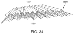
- FIG. 34 is a perspective view of the combination rainscreen/lath assembly of FIG. 32 ;
- FIG. 35 is a front view of the combination rainscreen/lath assembly of FIG. 32 with another combination rainscreen/lath assembly.
- FIG. 36 is a front view of another embodiment lath layer of a combination rainscreen/lath assembly constructed in accordance with the principles of the present invention.
- embodiments of this disclosure relate to a combination lath and rainscreen provided in a single assembly and to methods of installation.
- Various embodiments simplify installation thereby reducing labor costs and installation requirements.
- various embodiments are non-corrosive and are metal-free. Advantages of being metal-free include reduced weight, reduced cost, safer handling, and less interference with radio frequency signals.
- An example combination lath and rainscreen assembly generally includes two layers.
- One layer is a rainscreen layer preferably made of spunbond, which is preferably made of polypropylene.
- the spunbond has a sheet thickness of 0.020 to 0.030 gauge.
- the spunbond is crimped or folded to form corrugated spunbond having grooves or ridges.
- spunbond 161 has been crimped to form outwardly extending portions 169 proximate a front side 162 and inwardly extending portions 170 proximate a rear side 163 thereby forming outwardly facing cavities 172 and inwardly facing cavities 173 .
- the portions 169 and 170 can have 1 ⁇ 4 to 1 ⁇ 2 inch (preferably 5/16 inch) diameters D 1 and the peaks of adjacent portions 169 and adjacent portions 170 can be spaced (spaces S 1 ) 1 ⁇ 4 to 1 ⁇ 2 inch (preferably 5 ⁇ 8 inch) apart so the corrugated spunbond's thickness T 1 is 1 ⁇ 4 to 3 ⁇ 4 inch (preferably 5/16 inch). Any suitable crimping or folding technique can be used.
- crimping can be accomplished by inserting the spunbond between rollers 198 and 198 ′ including mating protrusions 199 and 199 ′.
- the spunbond can optionally be perforated prior to crimping.
- perforations 175 can be formed in the spunbond 161 in a staggered pattern and each perforation having a 1 ⁇ 4 to 1 ⁇ 2 inch (preferably 5/16 inch) diameter D 2 with the centers generally spaced (spaces S 2 , S 3 ) 1 ⁇ 2 inch to 1 inch (preferably 3 ⁇ 4 inch) apart. Any suitable perforation technique can be used. For example, as shown in FIG.
- perforation can be accomplished by inserting the spunbond between two rollers, a perforating roller 194 having a plurality of outwardly extending pins 195 configured and arranged to pierce the spunbond and a roller 196 having slots 197 configured and arranged to receive the pins 195 as they extend through the spunbond.
- the perforations can be any suitable size, any suitable shape, and arranged in any suitable pattern.
- the assembly can include spunbond without perforations, spunbond with perforations, or spunbond alternating between no perforations and perforations. The alternating no perforations and perforations can be on the same sheet or with alternating sheets of spunbond.
- FIG. 31 Another example spunbond 1061 is shown in FIG. 31 .
- Spunbond 1061 has been folded to form outwardly extending portions 1069 proximate a front side 1062 and inwardly extending portions 1070 proximate a rear side 1063 thereby forming outwardly facing cavities 1072 and inwardly facing cavities 1073 .
- the spunbond 1061 can be folded to have a height H 1 of 1 ⁇ 4 to 3 ⁇ 4 inch (preferably 3 ⁇ 8 inch) with a space S 4 of 1 ⁇ 4 to 3 ⁇ 4 inch (preferably 3 ⁇ 8 inch) between adjacent peaks of the outwardly and inwardly extending portions. Any suitable folding technique can be used.
- the other layer is a lath layer preferably made of a scrim material, which is made of a fiberglass material with an alkaline resistant coating suitable for a fire rating.
- the scrim material has a thickness of 0.025 to 0.035 gauge.
- the lath layer is operatively connected to the spunbond layer by any suitable attachment means including but not limited to an adhesive, a fastener, or stitching.
- the scrim material includes a plurality of voids or apertures configured and arranged to receive scratch coat and is preferably a heavier weight than typical scrim material to better support and secure the scratch coat.
- scratch coat When scratch coat is applied onto the lath, some of the scratch coat extends through the voids or apertures in the lath and can enter the outward facing cavities and the perforations of the spunbond thereby providing additional adherence or bonding.
- scrim material used throughout can be substituted with a suitable lath layer material.
- the assembly includes that it is flexible (e.g., it is easy to roll and transport), it is lightweight, it does not crack, it is easy cut, it is easier and safer to handle, and it is less expensive.
- types of walls to which the combination rainscreen/lath assembly can be connected include wood studs, sheathing, and weather resistant barrier (“WRB”); steel studs, sheathing, and WRB; structural insulated panes (“SIP”) wall systems; masonry walls with WRB; poured concrete walls with WRB; insulated concrete forms (“ICF”) with poured concrete cores and WRB.
- a combination rainscreen/lath assembly 260 includes a rainscreen layer made of spunbond 261 and a lath layer made of scrim material 280 operatively connected to a front side 262 of the spunbond 261 .
- the spunbond 261 is of similar corrugated construction as spunbond 161 and it is recognized that spunbond 161 or any other suitable material and configuration can be used.
- An adhesive is applied horizontally onto the spunbond 261 in at least one row so that the outwardly extending portions 269 of the spunbond 261 adhere to the scrim material 280 .
- the scrim material 280 overhangs downward from the spunbond 261 to form a skirt portion 285 .
- the apertures 288 in the scrim material 280 and the outward facing cavities 272 in the spun bond 261 provide voids in which scratch coat can extend when the scratch coat is applied onto the front side 281 of the scrim material 280 .
- the spunbond layer can be 22 inches high and the lath layer can be 24 inches high, and the layers can come in 50 foot long rolls, but it is recognized that any suitable dimensions can be used.
- the assembly 1160 includes a spunbond layer 1161 and a lath layer 1180 that are both crimped or folded to form corrugated layers having grooves or ridges. These layers can be crimped or folded as described for spunbond 161 or 1061 or any other suitable crimping or folding technique.
- Spunbond layer 1161 has been crimped to form outwardly extending portions 1169 proximate a front side 1162 and inwardly extending portions 1170 proximate a rear side 1163 thereby forming outwardly facing cavities 1172 and inwardly facing cavities 1173 .
- spunbond 161 , 1061 , and 1161 are shown and described, it is recognized that any suitable rainscreen material can be used in any suitable configuration to form corrugated rainscreen.
- the term “spunbond” used throughout can be substituted with a suitable rainscreen material. It is recognized that crimping or folding the lath layer is optional, and the lath layer crimping or folding can have a different configuration than that of the spunbond layer.
- the lath layer 1180 is operatively connected to the spunbond layer 1161 with any suitable attachment means including but not limited to an adhesive, a fastener, or stitching.
- the crimped or folded lath layer provides a structure to better receive and secure the scratch coat because the space between the lath layer and the spunbond accommodates the scratch coat.
- the spunbond 1161 extends upward from the lath layer 1180 to form a skirt 1165 and the lath layer 1180 extends downward from the spunbond 1161 to form a skirt 1185 .
- FIG. 35 it is illustrated how two or more assemblies 1160 can be installed.
- the first assembly 1160 a is positioned below the second assembly 1160 b and, in one embodiment, the assemblies are preferably offset a suitable amount.
- the spunbond layer of the second assembly 1160 b is positioned over the skirt 1165 a of the spunbond layer 1161 a so that it abuts the lath layer 1180 a and the skirt 1185 b extends over a top portion of the lath layer 1180 a .
- the crimping patterns of the spunbond and lath layers do not need to correspond and can have different configurations.
- the crimping patterns of the respective layers mate to align drainage channels (for the spunbond layers) or apertures to receive scratch coat (for the lath layers).
- This lath layer 1190 includes warp strands 1191 and weft strands 1192 interwoven to form apertures 1198 configured and arranged to receive scratch coat.
- the warp strands 1191 include one or more concentrated portion 1199 that is a group of at least two warp strands spaced closer together than other portions of the lath layer.
- the one or more concentrated portion 1199 provides additional strength for receiving fasteners to secure the assembly to studs or other structural anchor members.
- Two or more concentrated portions 1199 can be spaced to correspond with studs or other structural anchor members.
- the concentrated portion 1199 can also provide an area where the lath layer 1190 is secured to the spunbond layer.
- the warp strands 1191 and the weft strands 1192 are approximately 1 ⁇ 8 inch wide and are generally spaced approximately 1 ⁇ 2 inch from adjacent warp strands 1191 or weft strands 1192 and, in the concentrated portion 1199 , the warp strands 1191 are spaced approximately 1 ⁇ 8 inch apart. With three strands of warp strands 1191 , the concentrated portion 1199 is approximately 5 ⁇ 8 inch wide.
- the lath layer 1190 is 271 ⁇ 2 inches wide and 1500 to 2000 feet long. The lath layer 1190 can be coated, preferably with a suitable fire proof material, to add structure to both the lath layer and the assembly. It is recognized that the lath layer 1190 can be used with or without corrugated configurations.
- FIGS. 7 a - 13 An embodiment method of installation, illustrated in FIGS. 7 a - 13 , generally includes overlapping first and second combination rainscreen/lath assemblies 360 a and 360 b .
- the assemblies 360 a and 360 b are the same but it is recognized that they can be different.
- FIGS. 10 and 13 illustrate optional rear layers 334 a and 334 b that are preferably made of high impact polystyrene (“HIPS”) that has been crimped at 3/16 inch diameters and are 24 inches in height.
- FIGS. 9 and 12 illustrate middle layers 361 a and 361 b that are preferably made of perforated, lightly crimped (1 ⁇ 8 to 1 ⁇ 4 inch pattern), heavy spunbond (0.020 to 0.030 gauge) polypropylene and are 24 inches in height.
- HIPS high impact polystyrene
- the middle layers 361 a and 361 b are positioned with vertical offsets approximately 2 inches so that skirts of approximately 2 inches of the rear layers 334 a and 334 b extend upward from the middle layers 361 a and 361 b and skirts of approximately 2 inches of the middle layers 361 a and 361 b extend downward from the rear layers 334 a and 334 b .
- FIGS. 8 and 11 illustrate front layers 380 a and 380 b that are preferably made of heavy scrim material (0.025 to 0.035 gauge) and are 26 inches in height.
- the tops of the front layers 380 a and 380 b align with the tops of the middle layers 361 a and 361 b and skirts of approximately 2 inches extend downward from the middle layers 361 a and 361 b .
- the assembly 360 a is first secured to the studs using suitable fasteners such as nails or staples.
- the bottom of the rear layer 334 b is positioned on top of the rear layer 334 a skirt to abut the tops of the middle layer 361 a and the front layer 380 a so that approximately 2 inches of the middle layer 361 b and approximately 4 inches of the front layer 380 b extend downward over the front layer 380 a .
- suitable fasteners such as nails or staples.
- the bottom of the rear layer 334 b is positioned on top of the rear layer 334 a skirt to abut the tops of the middle layer 361 a and the front layer 380 a so that approximately 2 inches of the middle layer 361 b and approximately 4 inches of the front layer
- FIGS. 14 a - 18 An embodiment method of installation, illustrated in FIGS. 14 a - 18 , generally includes overlapping first and second combination rainscreen/lath assemblies 460 a and 460 b .
- the assemblies 460 a and 460 b are the same but it is recognized that they can be different.
- FIGS. 16 and 18 illustrate rear layers 461 a and 461 b that are preferably made of crimped spunbond polypropylene and are preferably 24 inches in height, 50 feet in length (rolls).
- FIGS. 15 and 17 illustrate front layers 480 a and 480 b that are preferably made of scrim material and are 24 inches in height, 50 feet in length (rolls).
- the front layers 480 a and 480 b are positioned with vertical offsets approximately 2 inches relative to the rear layers 461 a and 461 b so that skirts of approximately 2 inches of the rear layers 461 a and 461 b extend upward from the front layers 480 a and 480 b and skirts of approximately 2 inches of the front layers 480 a and 480 b extend downward from the rear layers 461 a and 461 b .
- the assembly 460 a is first secured to the studs using suitable fasteners such as nails or staples.
- the bottom of the rear layer 461 b is positioned on top of the rear layer 461 a skirt to abut the top of the front layer 480 a so that approximately 2 inches of the front layer 480 b extends downward over the front layer 480 a .
- the assembly 480 b can be horizontally offset relative to the assembly 480 a , as shown. Although two assemblies are shown, it is recognized that any suitable number of assemblies can be installed in such overlapping fashion. It is recognized that any suitable dimensions can be used.
- the corrugated spunbond layer creates spaces between the corrugated spunbond layer and adjacent materials.
- An embodiment method of installation illustrated in FIGS. 19 - 22 , generally includes sheathing 504 connected to studs 503 , which could be wood or steel studs, and water resistant barrier 532 connected to the sheathing 504 , as is known in the art.
- the studs 503 are spaced apart to create stud cavities 503 a therebetween.
- a weep screed 512 is connected to the sheathing 504 proximate the foundation so that a bottom portion of the weep screed 512 overhangs a top portion of the foundation.
- the water resistant barrier 532 is positioned over approximately 2 inches of the top portion of the weep screed 512 .
- a starter strip 536 including spunbond 548 positioned about a front 538 , a bottom 541 , and a rear 539 of a base 537 is positioned within a cavity 521 of the weep screed 512 with front and rear flanges 549 and 552 of the spunbond 548 extending upward approximately 4 inches.
- the base 537 is made of corrugated HIPS at 3/16 inch by 2 inches. Although dimensions are listed for embodiments, it is recognized that any suitable dimensions can be used.
- the combination rainscreen/lath assembly 560 is positioned with the spunbond 561 facing rearward proximate the water resistant barrier 532 and the lath 580 facing frontward.
- the spunbond 561 is made of polypropylene and is perforated and corrugated to 5/16 inch diameters.
- the lath 580 is scrim material including apertures 588 .
- the spunbond 561 creates inward facing cavities 573 between the inwardly extending portions 570 and creates outward facing cavities 572 between the outwardly extending portions 569 .
- the first row of the assembly 560 is positioned with the bottom of the spunbond 561 abutting a top 540 of the starter strip base 537 between the rear and front flanges 549 and 552 .
- vented edge material 530 with apertures 530 a can be used with ( FIG. 21 ) or without ( FIG. 22 ) a starter strip 536 , as known in the art.
- the lath 680 is scrim material including apertures 688 .
- the spunbond 661 creates inward facing cavities 673 between the inwardly extending portions 670 and creates outward facing cavities 672 between the outwardly extending portions 669 .
- the assembly 660 can be installed in a similar manner as the assembly 560 using a weep screed and edging.
- another embodiment method of installation includes attaching a suitable weep screed (not shown) and optional deflector (not shown) along a bottom of a wall at a code approved elevation from an existing exterior grade and attaching suitable window and door flashing (not shown), as known in the art.
- a weather resistant barrier (“WRB”) 832 applied to the wall has a bottom that is positioned to overlap a back flange of the weep screed without interrupting vent slots in the weep screed.
- the weep screed accommodates air flow and drainage capacity, and an example of a suitable weep screed is L&R Weep Screed, LR 3501, by Masonry Technology, Inc.
- a weep screed deflector such as WSD 1309 by Masonry Technology, Inc.
- WSD 1309 by Masonry Technology, Inc.
- a bug screen can also be used as is known in the art. Openings for windows, doors, etc. preferably terminate with edging, and an example of suitable edging is MTI Edge Metal, MEM 3168, by Masonry Technology, Inc.
- a starter strip 836 for example Corrugated Lath Starter Strip, CLSS 2316, by Masonry Technology, Inc., is installed so that the bottom edge of the starter strip's base 837 is seated into the cavity of the weep screed (not shown) to ensure that no scratch coat mortar reaches the weep screed's vent slots when it is applied.
- An example of a suitable base is 2 inches high corrugated high impact polystyrene.
- the starter strip's spunbond 848 is wrapped about the base 837 so that a rear flange 852 and a front flange 849 extend upward from the base's bottom.
- a combination rainscreen/lath assembly includes corrugated spunbond and lath offset vertically about 2 inches so that about 2 inches of spunbond extend upward from the lath and about 2 inches of lath extend downward from the spunbond.
- a first course of combination rainscreen/lath assembly 860 is installed horizontally with a bottom edge of corrugated spunbond 861 abutting a top edge of the base 837 . Fasteners such as nails or stapes are inserted through the assembly 860 into the wall, preferably at each stud, in accordance with code requirements.
- the front flange 849 is positioned over the base 837 and the spunbond 861 , and the skirt 885 of the lath 880 is positioned over the spunbond 861 , as shown in FIGS. 26 - 28 .
- a second course of combination rainscreen/lath assembly 860 ′ is installed horizontally with a bottom portion of the second corrugated spunbond (not shown) overlapping a top portion of the first corrugated spunbond 861 and the skirt 885 ′ of the second lath 880 ′ is positioned over the first lath 880 , as shown in FIG. 29 .
- Fasteners such as nails or stapes are inserted through the assembly 860 ′ into the wall, preferably at each stud, in accordance with code requirements.
- a third course of combination rainscreen/lath assembly 860 ′′ is installed horizontally with a bottom portion of the third corrugated spunbond (not shown) overlapping a top portion of the second corrugated spunbond (not shown) and the skirt 885 ′′ of the third lath 880 ′′ is positioned over the second lath 880 ′, as shown in FIG. 30 .
- Fasteners such as nails or stapes are inserted through the assembly 860 ′′ into the wall, preferably at each stud, in accordance with code requirements.
- the top of the final course of combination rainscreen/lath assembly preferably terminates with a vented metal edge with venting capacity, for example Vented MTI Edge Metal, VMEM 3168, by Masonry Technology, Inc.
- the top of the vented metal edge is preferably installed approximately 3 ⁇ 8 inch down from the bottom of the soffit, and a starter strip is positioned with its “bottom” edge seated into the vented metal edge cavity to ensure no scratch coat goes into the vent slots.
- the top edge of the combination rainscreen/lath assembly's corrugated spunbond preferably contacts the bottom edge of the starter strip's base, with the starter strip's rear and front flanges of spunbond extending downward and overlapping the top portion of the assembly's spunbond on opposing sides, and the assembly's lath extending upward and overlapping the front flange of spunbond.
- the lath is configured and arranged to receive scratch coat within its apertures, and the corrugated spunbond provides areas for scratch coat extending through the apertures proximate the opposing side of the lath to which the scratch coat was applied. If the corrugated spunbond includes perforations or apertures, the scratch coat can also extend through at least some of these apertures for additional adherence and support. Preferably the spunbond's apertures are large enough to incorporate some of the scratch coat but not large enough for the scratch coat to extend through the spunbond and block the spunbond's channels.
- the corrugated spun bond also provides a drainage plane, which also provides a gap or thermo-break resulting in an insulation R-value for energy efficiency.
- the spunbond's channels which form the drainage plane, allow for venting of air and moisture thereby assisting in reducing any accumulation of moisture. Moisture can move through the scratch coat to drain through the channels and out of the voids. Because there are voids or venting in the bottom and the top, there is a “chimney effect” to assist in venting.
Landscapes
- Engineering & Computer Science (AREA)
- Architecture (AREA)
- Civil Engineering (AREA)
- Structural Engineering (AREA)
- Physics & Mathematics (AREA)
- Electromagnetism (AREA)
- Building Environments (AREA)
Abstract
Description
Claims (10)
Priority Applications (1)
| Application Number | Priority Date | Filing Date | Title |
|---|---|---|---|
| US17/915,016 US12241253B2 (en) | 2020-03-30 | 2021-03-23 | Combination rainscreen/lath assembly and method of installing same |
Applications Claiming Priority (4)
| Application Number | Priority Date | Filing Date | Title |
|---|---|---|---|
| US202063001846P | 2020-03-30 | 2020-03-30 | |
| US202063023480P | 2020-05-12 | 2020-05-12 | |
| PCT/US2021/023612 WO2021202161A1 (en) | 2020-03-30 | 2021-03-23 | Combination rainscreen/lath assembly and method of installing same |
| US17/915,016 US12241253B2 (en) | 2020-03-30 | 2021-03-23 | Combination rainscreen/lath assembly and method of installing same |
Publications (2)
| Publication Number | Publication Date |
|---|---|
| US20230151615A1 US20230151615A1 (en) | 2023-05-18 |
| US12241253B2 true US12241253B2 (en) | 2025-03-04 |
Family
ID=77928335
Family Applications (1)
| Application Number | Title | Priority Date | Filing Date |
|---|---|---|---|
| US17/915,016 Active 2041-07-06 US12241253B2 (en) | 2020-03-30 | 2021-03-23 | Combination rainscreen/lath assembly and method of installing same |
Country Status (2)
| Country | Link |
|---|---|
| US (1) | US12241253B2 (en) |
| WO (1) | WO2021202161A1 (en) |
Families Citing this family (1)
| Publication number | Priority date | Publication date | Assignee | Title |
|---|---|---|---|---|
| US12241253B2 (en) * | 2020-03-30 | 2025-03-04 | Masonry Technology, Inc. | Combination rainscreen/lath assembly and method of installing same |
Citations (41)
| Publication number | Priority date | Publication date | Assignee | Title |
|---|---|---|---|---|
| US1802779A (en) * | 1927-08-01 | 1931-04-28 | William H Quade | Plaster and stucco reenforcing base |
| US2212126A (en) * | 1932-06-14 | 1940-08-20 | Phillips Roy | Flexible suspension for wall and ceiling finishes |
| US3888087A (en) * | 1973-04-11 | 1975-06-10 | Oivind Lorentzen Activities In | Foundation wall protective sheet |
| US4381630A (en) * | 1980-12-01 | 1983-05-03 | Koester John H | Foundation vent structure |
| US4795562A (en) * | 1985-09-13 | 1989-01-03 | Walsh James W | Membrane batch-processing apparatus |
| US5099627A (en) * | 1990-09-28 | 1992-03-31 | Benjamin Obdyke Incorporated | Ventilated roof construction and method |
| US5224316A (en) * | 1991-08-05 | 1993-07-06 | Fredericks Chester P | Textured insulated building panel |
| US6131353A (en) * | 1998-06-03 | 2000-10-17 | Mbt Holding Ag | Composite weather barrier |
| US6298620B1 (en) * | 2000-04-10 | 2001-10-09 | Michael Hatzinikolas | Moisture control panel |
| US6355333B1 (en) * | 1997-12-09 | 2002-03-12 | E. I. Du Pont De Nemours And Company | Construction membrane |
| US20030037499A1 (en) * | 2001-08-21 | 2003-02-27 | Coulton Michael S. | Spacer for providing drainage passageways within building structures |
| US20040255533A1 (en) * | 2003-06-18 | 2004-12-23 | Koester John H. | Moisture drainage product, wall system incorporating such product and method therefore |
| US6883284B1 (en) * | 2003-03-21 | 2005-04-26 | Paul R. Burgunder | Masonry wall device |
| US6964136B2 (en) * | 2002-06-17 | 2005-11-15 | Pacc Systems I.P., Llc | Flashing and weep apparatus for masonry wall window and door installations |
| US20060117686A1 (en) * | 2004-11-23 | 2006-06-08 | Mankell Kurt O | Insulation batt having integral baffle vent |
| US20060281379A1 (en) * | 2005-06-10 | 2006-12-14 | Fabrene Inc. | Breathable, water resistant fabric |
| US20060286347A1 (en) * | 2005-06-17 | 2006-12-21 | Building Materials Investment Corporation | Breathable non-asphaltic roofing underlayment having tailorable breathability |
| US20070051069A1 (en) * | 2005-09-07 | 2007-03-08 | Benjamin Obdyke Incorporated | Composite Building Material for Cementitious Material Wall Assembly |
| US20080260993A1 (en) * | 2007-04-18 | 2008-10-23 | Masonry Technology Incorporated | Moisture drainage product having limited bearing surface, wall system incorporating such and method therefore |
| US20090158683A1 (en) * | 2007-12-20 | 2009-06-25 | Theresa Ann Weston | Multiple sheet building wrap for use in external wall assemblies having wet-applied facades |
| US7625827B2 (en) * | 2003-12-19 | 2009-12-01 | Basf Construction Chemicals, Llc | Exterior finishing system and building wall containing a corrosion-resistant enhanced thickness fabric and method of constructing same |
| US7632763B2 (en) | 2003-12-19 | 2009-12-15 | Saint Gobain Technical Fabrics America, Inc. | Enhanced thickness fabric and method of making same |
| US20100043326A1 (en) * | 2008-08-21 | 2010-02-25 | Masonry Technology, Inc. | Wall Structure with Moisture Diverter and Method of Making Same |
| US20100043307A1 (en) * | 2008-08-21 | 2010-02-25 | Masonry Technology, Inc. | Weep Screed with Weep Screed Deflector and Method of Using Same |
| US20100101159A1 (en) * | 2007-03-21 | 2010-04-29 | James Gleeson | Framed Wall Construction and Method |
| US20100236158A1 (en) * | 2009-03-18 | 2010-09-23 | Peter Carbonaro | Apparatus for a wind resistant and post load re-tensioning system utilizing a composite fabric and attachment apparatus |
| US20120183744A1 (en) * | 2011-01-17 | 2012-07-19 | Keene James R | Drainage mat |
| US20120183746A1 (en) * | 2011-01-17 | 2012-07-19 | Keene James R | Drainage mat |
| US20120247040A1 (en) * | 2011-04-01 | 2012-10-04 | Boral Stone Products Llc | Apparatuses and methods for a lath and rain screen assembly |
| US20120304565A1 (en) * | 2011-06-06 | 2012-12-06 | Boral Stone Products Llc | Apparatuses and Methods for an Improved Lath, Vapor Control Layer and Rain Screen Assembly |
| US20130276392A1 (en) * | 2012-03-23 | 2013-10-24 | Mortar Net Usa, Ltd. | Lath |
| US9145688B2 (en) * | 2007-06-28 | 2015-09-29 | Spiderlath, Inc. | Lath support system |
| US20170037637A1 (en) * | 2015-08-03 | 2017-02-09 | Bayer Materialscience Llc | Stucco wall structure |
| US9783980B2 (en) * | 2014-07-01 | 2017-10-10 | VaproShield, LLC | Building membrane with drainage matrix and horizontal adhesive portions |
| US20180209140A1 (en) * | 2017-01-23 | 2018-07-26 | John G. Hoggatt | Drainage and ventilation mat for building exterior wall, roof and basement assemblies |
| US10125489B2 (en) * | 2014-07-01 | 2018-11-13 | VaproShield, LLC | Self adhering weather resistant vapor permeable air barrier membrane with rain plane matrix |
| US10196812B1 (en) * | 2015-09-29 | 2019-02-05 | Frank L. Duffy | Weep screed |
| US20200340238A1 (en) * | 2018-04-10 | 2020-10-29 | Innovation Calumet Llc | Drainage channel for use in a building wall |
| US20200354965A1 (en) * | 2019-05-08 | 2020-11-12 | II Harold C. Attebery | Panelized lath and drainage plane system for building exteriors |
| US20210404177A1 (en) * | 2018-11-29 | 2021-12-30 | John H. Koester | Combination lath/rainscreen assemblies and methods of installation and manufacture |
| US20230151615A1 (en) * | 2020-03-30 | 2023-05-18 | John H. Koester | Combination rainscreen/lath assembly and method of installing same |
-
2021
- 2021-03-23 US US17/915,016 patent/US12241253B2/en active Active
- 2021-03-23 WO PCT/US2021/023612 patent/WO2021202161A1/en not_active Ceased
Patent Citations (54)
| Publication number | Priority date | Publication date | Assignee | Title |
|---|---|---|---|---|
| US1802779A (en) * | 1927-08-01 | 1931-04-28 | William H Quade | Plaster and stucco reenforcing base |
| US2212126A (en) * | 1932-06-14 | 1940-08-20 | Phillips Roy | Flexible suspension for wall and ceiling finishes |
| US3888087A (en) * | 1973-04-11 | 1975-06-10 | Oivind Lorentzen Activities In | Foundation wall protective sheet |
| US4381630A (en) * | 1980-12-01 | 1983-05-03 | Koester John H | Foundation vent structure |
| US4795562A (en) * | 1985-09-13 | 1989-01-03 | Walsh James W | Membrane batch-processing apparatus |
| US5099627A (en) * | 1990-09-28 | 1992-03-31 | Benjamin Obdyke Incorporated | Ventilated roof construction and method |
| US5224316A (en) * | 1991-08-05 | 1993-07-06 | Fredericks Chester P | Textured insulated building panel |
| US6355333B1 (en) * | 1997-12-09 | 2002-03-12 | E. I. Du Pont De Nemours And Company | Construction membrane |
| US6131353A (en) * | 1998-06-03 | 2000-10-17 | Mbt Holding Ag | Composite weather barrier |
| US6298620B1 (en) * | 2000-04-10 | 2001-10-09 | Michael Hatzinikolas | Moisture control panel |
| US20030037499A1 (en) * | 2001-08-21 | 2003-02-27 | Coulton Michael S. | Spacer for providing drainage passageways within building structures |
| US6594965B2 (en) * | 2001-08-21 | 2003-07-22 | Benjamin Obdyke Incorporated | Spacer for providing drainage passageways within building structures |
| US6964136B2 (en) * | 2002-06-17 | 2005-11-15 | Pacc Systems I.P., Llc | Flashing and weep apparatus for masonry wall window and door installations |
| US6883284B1 (en) * | 2003-03-21 | 2005-04-26 | Paul R. Burgunder | Masonry wall device |
| US20040255533A1 (en) * | 2003-06-18 | 2004-12-23 | Koester John H. | Moisture drainage product, wall system incorporating such product and method therefore |
| US6990775B2 (en) * | 2003-06-18 | 2006-01-31 | Masonry Technology, Inc. | Moisture drainage product, wall system incorporating such product and method therefore |
| US20100000665A1 (en) * | 2003-12-19 | 2010-01-07 | Newton Mark J | Enhanced Thickness Fabric and Method of Making Same |
| US7699949B2 (en) | 2003-12-19 | 2010-04-20 | Saint-Gobain Technical Fabrics America, Inc. | Enhanced thickness fabric and method of making same |
| US7902092B2 (en) | 2003-12-19 | 2011-03-08 | Basf Construction Chemicals, Llc | Exterior finishing system and building wall containing a corrosion-resistant enhanced thickness fabric and method of constructing same |
| US7867350B2 (en) | 2003-12-19 | 2011-01-11 | Saint Gobain Technical Fabrics America, Inc. | Enhanced thickness fabric and method of making same |
| US8298967B2 (en) | 2003-12-19 | 2012-10-30 | Basf Corporation | Exterior finishing system and building wall containing a corrosion-resistant enhanced thickness fabric |
| US7786026B2 (en) | 2003-12-19 | 2010-08-31 | Saint-Gobain Technical Fabrics America, Inc. | Enhanced thickness fabric and method of making same |
| US7625827B2 (en) * | 2003-12-19 | 2009-12-01 | Basf Construction Chemicals, Llc | Exterior finishing system and building wall containing a corrosion-resistant enhanced thickness fabric and method of constructing same |
| US7632763B2 (en) | 2003-12-19 | 2009-12-15 | Saint Gobain Technical Fabrics America, Inc. | Enhanced thickness fabric and method of making same |
| US8187401B2 (en) | 2003-12-19 | 2012-05-29 | Saint-Gobain Adfors Canada, Ltd. | Enhanced thickness fabric and method of making same |
| US20060117686A1 (en) * | 2004-11-23 | 2006-06-08 | Mankell Kurt O | Insulation batt having integral baffle vent |
| US20060281379A1 (en) * | 2005-06-10 | 2006-12-14 | Fabrene Inc. | Breathable, water resistant fabric |
| US20060286347A1 (en) * | 2005-06-17 | 2006-12-21 | Building Materials Investment Corporation | Breathable non-asphaltic roofing underlayment having tailorable breathability |
| US20070051069A1 (en) * | 2005-09-07 | 2007-03-08 | Benjamin Obdyke Incorporated | Composite Building Material for Cementitious Material Wall Assembly |
| US20100101159A1 (en) * | 2007-03-21 | 2010-04-29 | James Gleeson | Framed Wall Construction and Method |
| US20080260993A1 (en) * | 2007-04-18 | 2008-10-23 | Masonry Technology Incorporated | Moisture drainage product having limited bearing surface, wall system incorporating such and method therefore |
| US9145688B2 (en) * | 2007-06-28 | 2015-09-29 | Spiderlath, Inc. | Lath support system |
| US20090158683A1 (en) * | 2007-12-20 | 2009-06-25 | Theresa Ann Weston | Multiple sheet building wrap for use in external wall assemblies having wet-applied facades |
| US20100043326A1 (en) * | 2008-08-21 | 2010-02-25 | Masonry Technology, Inc. | Wall Structure with Moisture Diverter and Method of Making Same |
| US20100043307A1 (en) * | 2008-08-21 | 2010-02-25 | Masonry Technology, Inc. | Weep Screed with Weep Screed Deflector and Method of Using Same |
| US20100236158A1 (en) * | 2009-03-18 | 2010-09-23 | Peter Carbonaro | Apparatus for a wind resistant and post load re-tensioning system utilizing a composite fabric and attachment apparatus |
| US8631615B2 (en) * | 2009-03-18 | 2014-01-21 | Windwrap, Inc. | Apparatus for a wind resistant and post load re-tensioning system utilizing a composite fabric and attachment apparatus |
| US8910436B2 (en) * | 2009-03-18 | 2014-12-16 | Windwrap, Inc. | Apparatus for a wind resistant and post load re-tensioning system utilizing a composite fabric and attachment apparatus |
| US20120183746A1 (en) * | 2011-01-17 | 2012-07-19 | Keene James R | Drainage mat |
| US8734932B2 (en) * | 2011-01-17 | 2014-05-27 | Keene Building Products Co., Inc. | Drainage mat |
| US20120183744A1 (en) * | 2011-01-17 | 2012-07-19 | Keene James R | Drainage mat |
| US20120247040A1 (en) * | 2011-04-01 | 2012-10-04 | Boral Stone Products Llc | Apparatuses and methods for a lath and rain screen assembly |
| US20120304565A1 (en) * | 2011-06-06 | 2012-12-06 | Boral Stone Products Llc | Apparatuses and Methods for an Improved Lath, Vapor Control Layer and Rain Screen Assembly |
| US20130276392A1 (en) * | 2012-03-23 | 2013-10-24 | Mortar Net Usa, Ltd. | Lath |
| US10125489B2 (en) * | 2014-07-01 | 2018-11-13 | VaproShield, LLC | Self adhering weather resistant vapor permeable air barrier membrane with rain plane matrix |
| US9783980B2 (en) * | 2014-07-01 | 2017-10-10 | VaproShield, LLC | Building membrane with drainage matrix and horizontal adhesive portions |
| US20170037637A1 (en) * | 2015-08-03 | 2017-02-09 | Bayer Materialscience Llc | Stucco wall structure |
| US10196812B1 (en) * | 2015-09-29 | 2019-02-05 | Frank L. Duffy | Weep screed |
| US20180209140A1 (en) * | 2017-01-23 | 2018-07-26 | John G. Hoggatt | Drainage and ventilation mat for building exterior wall, roof and basement assemblies |
| US10822791B2 (en) * | 2017-01-23 | 2020-11-03 | John G. Hoggatt | Drainage and ventilation mat for building exterior wall, roof and basement assemblies |
| US20200340238A1 (en) * | 2018-04-10 | 2020-10-29 | Innovation Calumet Llc | Drainage channel for use in a building wall |
| US20210404177A1 (en) * | 2018-11-29 | 2021-12-30 | John H. Koester | Combination lath/rainscreen assemblies and methods of installation and manufacture |
| US20200354965A1 (en) * | 2019-05-08 | 2020-11-12 | II Harold C. Attebery | Panelized lath and drainage plane system for building exteriors |
| US20230151615A1 (en) * | 2020-03-30 | 2023-05-18 | John H. Koester | Combination rainscreen/lath assembly and method of installing same |
Non-Patent Citations (26)
| Title |
|---|
| Adfors Saint-Gobain; FibaLath Installation Instructions; 1 page; Apr. 2019. |
| Adfors Saint-Gobain; FibaLath Sell Sheet; 2 pages; Apr. 2018. |
| Adfors; Fibalath product overview; known of prior to Mar. 30, 2020; accessed at https://us.adfors.com/facade-reinforcement-mesh/fibalath on Jun. 3, 2022; 2 pages. |
| Adfors; Industrial Fabrics brochure; Sep. 2018; 2 pages. |
| Amico; Hydrodry Moisture Management Solution brochure; 8 pages; date of brochure unknown; HYDRODRY trademark registration date of first use Jul. 31, 2019. |
| avintiv.com; Typar Spunbond Polypropylene; http://www.technicalnonwovens.com/product/typar-spunbond-polypropylene; accessed Mar. 19, 2020; 2 pages. |
| BASF Wall Systems; PermaLath 1000 Product Bulletin 1032008; 2007; 4 pages. |
| BASF; PermaLath 1000 Product Bulletin rev 180808; 4 pages; 2018. |
| BASF; Senergy Sentry Stucco Ultra Wall System System Overview rev 150120; 4 pages; 2015. |
| Benjamin Obdyke; Cedar Breather Installation Instructions; 10 pages; 2017. |
| Coravent Incorporated; Cor-A-Vent's Siding Vent System: Your Rainscreen Ventilation Solution brochure; 12 pages; Jun. 2015. |
| Delta; Dorken Systems Inc.; Delta—Dry & Lath Installation Instructions; 3 pages; Apr. 11, 2019. |
| Delta; Dorken Systems Inc.; Delta—Dry & Lath product brochure; 4 pages; known of prior to Nov. 29, 2018. |
| Dorken; Delta-Dry & Lath Technical Data Sheet; 1 page; 2019. |
| ICC Evaluation Service; New Fiber Stucco Lath Creates Industry Buzz; 2 pages; Oct. 2008. |
| International Search Report and Written Opinion from PCT/US21/23612; Lee Young; 12 pages; Jun. 8, 2021. |
| Intertek; Code Compliance Research Report CCRR0249; 9 pages; known of prior to Mar. 30, 2020; Renewal Date Jun. 30, 2021. |
| Masonry Technology Incorporated; Building Moisture Management Solutions, Mar. 2019; 52 pages. |
| Masonry Technology Incorporated; Corrugated Lath Strip brochure; Mar. 2019; 2 pages. |
| Master Builders Solutions; PermaLath 1000 Product Bulletin; known of prior to Mar. 30, 2020; Apr. 2021; 3 pages. |
| Master Builders Solutions; PermaLath 1000 Test Results Technical Bulletin; known of prior to Mar. 30, 2020; Feb. 2022; 2 pages. |
| Master Wall Inc.; Fibalath product data sheet; rev 190101; 2019; 2 pages. |
| Risinger, Matt; Keep it Dry: How to Manage Moisture with Rainscreens; Builder Online; 3 pages; posted on Jun. 25, 2015; accesed at https://www.builderonline.com/building/building-science/keep-it-dry-how-to-manage-moisture-with-rainscreens_s?o=0 on Apr. 30, 2021. |
| Tamlyn; XtremeEnvelope Solutions; Tamlyn Water Management System Product & Technical Guide; 32 Pages; 2016. |
| Typar; Geotextiles Product Overview; 12 pages; TGT01; Aug. 2012. |
| US Fabrics; DuPont Spunbond Nonwoven Geotextiles; 3 pages; https://www.usfabricsinc.com/products/dupont-spunbond-nonwoven-geotextiles/; accessed Mar. 19, 2020. |
Also Published As
| Publication number | Publication date |
|---|---|
| WO2021202161A1 (en) | 2021-10-07 |
| US20230151615A1 (en) | 2023-05-18 |
Similar Documents
| Publication | Publication Date | Title |
|---|---|---|
| US9863146B2 (en) | Structural panel systems with a nested sidelap and method of securing | |
| US5511351A (en) | Drainage system for decks | |
| KR20070054744A (en) | Prefabricated Universal Structural Steel Panels and Panel Systems | |
| JP6047063B2 (en) | Thermal insulation structure and thermal insulation method for building | |
| US4277926A (en) | Vented insulation system for existing structure | |
| US20190316352A1 (en) | Wall/Roof Construction System and Related Method | |
| CN113216507A (en) | Modular partition | |
| US12241253B2 (en) | Combination rainscreen/lath assembly and method of installing same | |
| US6035584A (en) | Building system using replaceable insulated panels | |
| US8561359B2 (en) | Baffle vent with integral drift blocker | |
| FI126229B (en) | Multi-layer remediation building element | |
| US20030066249A1 (en) | Metal panel building system | |
| US6952901B2 (en) | Panel mounted shingles assembly with ventilating screen | |
| US1946560A (en) | Building unit | |
| US9151064B1 (en) | Construction device for releasing moisture from a building | |
| US20240287809A1 (en) | Building venting system | |
| US20080000170A1 (en) | Rafter Membrance Hold Down Clip | |
| US20210404177A1 (en) | Combination lath/rainscreen assemblies and methods of installation and manufacture | |
| US20200109555A1 (en) | Cavity wall through-wall flashing support system and method | |
| CN219773292U (en) | Fireproof isolation belt between inner layers of curtain wall | |
| US9719260B2 (en) | Roof baffle | |
| WO2016043784A1 (en) | A construction device for releasing moisture from a building | |
| EP3999692A1 (en) | Facade panel with integrated window system | |
| EP2547834B1 (en) | Air gap barrier | |
| JP7148951B2 (en) | Ventilation cross plate and ventilation roof using the same |
Legal Events
| Date | Code | Title | Description |
|---|---|---|---|
| FEPP | Fee payment procedure |
Free format text: ENTITY STATUS SET TO UNDISCOUNTED (ORIGINAL EVENT CODE: BIG.); ENTITY STATUS OF PATENT OWNER: SMALL ENTITY |
|
| FEPP | Fee payment procedure |
Free format text: ENTITY STATUS SET TO SMALL (ORIGINAL EVENT CODE: SMAL); ENTITY STATUS OF PATENT OWNER: SMALL ENTITY |
|
| STPP | Information on status: patent application and granting procedure in general |
Free format text: DOCKETED NEW CASE - READY FOR EXAMINATION |
|
| STPP | Information on status: patent application and granting procedure in general |
Free format text: NON FINAL ACTION MAILED |
|
| STPP | Information on status: patent application and granting procedure in general |
Free format text: RESPONSE TO NON-FINAL OFFICE ACTION ENTERED AND FORWARDED TO EXAMINER |
|
| STPP | Information on status: patent application and granting procedure in general |
Free format text: RESPONSE AFTER FINAL ACTION FORWARDED TO EXAMINER |
|
| STPP | Information on status: patent application and granting procedure in general |
Free format text: ADVISORY ACTION MAILED |
|
| STPP | Information on status: patent application and granting procedure in general |
Free format text: NOTICE OF ALLOWANCE MAILED -- APPLICATION RECEIVED IN OFFICE OF PUBLICATIONS |
|
| AS | Assignment |
Owner name: MASONRY TECHNOLOGY, INC., IOWA Free format text: ASSIGNMENT OF ASSIGNORS INTEREST;ASSIGNOR:KOESTER, JOHN H.;REEL/FRAME:069848/0602 Effective date: 20241216 Owner name: MASONRY TECHNOLOGY, INC., IOWA Free format text: ASSIGNMENT OF ASSIGNORS INTEREST;ASSIGNOR:KOESTER, JOHN H.;REEL/FRAME:069848/0359 Effective date: 20241216 |
|
| STPP | Information on status: patent application and granting procedure in general |
Free format text: PUBLICATIONS -- ISSUE FEE PAYMENT VERIFIED |
|
| STCF | Information on status: patent grant |
Free format text: PATENTED CASE |