US12219084B2 - Communication apparatus, information processing apparatus, and information processing method to feed back presence of a wireless signal - Google Patents
Communication apparatus, information processing apparatus, and information processing method to feed back presence of a wireless signal Download PDFInfo
- Publication number
- US12219084B2 US12219084B2 US17/425,003 US201917425003A US12219084B2 US 12219084 B2 US12219084 B2 US 12219084B2 US 201917425003 A US201917425003 A US 201917425003A US 12219084 B2 US12219084 B2 US 12219084B2
- Authority
- US
- United States
- Prior art keywords
- wireless signal
- antenna
- communication
- information
- information processing
- Prior art date
- Legal status (The legal status is an assumption and is not a legal conclusion. Google has not performed a legal analysis and makes no representation as to the accuracy of the status listed.)
- Active, expires
Links
Images


Classifications
-
- H—ELECTRICITY
- H04—ELECTRIC COMMUNICATION TECHNIQUE
- H04M—TELEPHONIC COMMUNICATION
- H04M1/00—Substation equipment, e.g. for use by subscribers
- H04M1/72—Mobile telephones; Cordless telephones, i.e. devices for establishing wireless links to base stations without route selection
- H04M1/724—User interfaces specially adapted for cordless or mobile telephones
- H04M1/72448—User interfaces specially adapted for cordless or mobile telephones with means for adapting the functionality of the device according to specific conditions
- H04M1/72454—User interfaces specially adapted for cordless or mobile telephones with means for adapting the functionality of the device according to specific conditions according to context-related or environment-related conditions
-
- G—PHYSICS
- G06—COMPUTING OR CALCULATING; COUNTING
- G06F—ELECTRIC DIGITAL DATA PROCESSING
- G06F3/00—Input arrangements for transferring data to be processed into a form capable of being handled by the computer; Output arrangements for transferring data from processing unit to output unit, e.g. interface arrangements
- G06F3/14—Digital output to display device ; Cooperation and interconnection of the display device with other functional units
- G06F3/147—Digital output to display device ; Cooperation and interconnection of the display device with other functional units using display panels
-
- G—PHYSICS
- G06—COMPUTING OR CALCULATING; COUNTING
- G06T—IMAGE DATA PROCESSING OR GENERATION, IN GENERAL
- G06T19/00—Manipulating 3D models or images for computer graphics
- G06T19/006—Mixed reality
-
- H—ELECTRICITY
- H01—ELECTRIC ELEMENTS
- H01Q—ANTENNAS, i.e. RADIO AERIALS
- H01Q1/00—Details of, or arrangements associated with, antennas
- H01Q1/12—Supports; Mounting means
- H01Q1/22—Supports; Mounting means by structural association with other equipment or articles
- H01Q1/24—Supports; Mounting means by structural association with other equipment or articles with receiving set
- H01Q1/241—Supports; Mounting means by structural association with other equipment or articles with receiving set used in mobile communications, e.g. GSM
- H01Q1/242—Supports; Mounting means by structural association with other equipment or articles with receiving set used in mobile communications, e.g. GSM specially adapted for hand-held use
- H01Q1/243—Supports; Mounting means by structural association with other equipment or articles with receiving set used in mobile communications, e.g. GSM specially adapted for hand-held use with built-in antennas
-
- H—ELECTRICITY
- H01—ELECTRIC ELEMENTS
- H01Q—ANTENNAS, i.e. RADIO AERIALS
- H01Q21/00—Antenna arrays or systems
- H01Q21/06—Arrays of individually energised antenna units similarly polarised and spaced apart
-
- H—ELECTRICITY
- H01—ELECTRIC ELEMENTS
- H01Q—ANTENNAS, i.e. RADIO AERIALS
- H01Q21/00—Antenna arrays or systems
- H01Q21/28—Combinations of substantially independent non-interacting antenna units or systems
-
- H—ELECTRICITY
- H01—ELECTRIC ELEMENTS
- H01Q—ANTENNAS, i.e. RADIO AERIALS
- H01Q3/00—Arrangements for changing or varying the orientation or the shape of the directional pattern of the waves radiated from an antenna or antenna system
- H01Q3/26—Arrangements for changing or varying the orientation or the shape of the directional pattern of the waves radiated from an antenna or antenna system varying the relative phase or relative amplitude of energisation between two or more active radiating elements; varying the distribution of energy across a radiating aperture
-
- H—ELECTRICITY
- H04—ELECTRIC COMMUNICATION TECHNIQUE
- H04B—TRANSMISSION
- H04B17/00—Monitoring; Testing
- H04B17/30—Monitoring; Testing of propagation channels
- H04B17/309—Measuring or estimating channel quality parameters
- H04B17/318—Received signal strength
-
- H—ELECTRICITY
- H04—ELECTRIC COMMUNICATION TECHNIQUE
- H04B—TRANSMISSION
- H04B7/00—Radio transmission systems, i.e. using radiation field
- H04B7/02—Diversity systems; Multi-antenna system, i.e. transmission or reception using multiple antennas
- H04B7/04—Diversity systems; Multi-antenna system, i.e. transmission or reception using multiple antennas using two or more spaced independent antennas
- H04B7/08—Diversity systems; Multi-antenna system, i.e. transmission or reception using multiple antennas using two or more spaced independent antennas at the receiving station
- H04B7/0868—Hybrid systems, i.e. switching and combining
- H04B7/088—Hybrid systems, i.e. switching and combining using beam selection
-
- G—PHYSICS
- G09—EDUCATION; CRYPTOGRAPHY; DISPLAY; ADVERTISING; SEALS
- G09G—ARRANGEMENTS OR CIRCUITS FOR CONTROL OF INDICATING DEVICES USING STATIC MEANS TO PRESENT VARIABLE INFORMATION
- G09G2340/00—Aspects of display data processing
- G09G2340/04—Changes in size, position or resolution of an image
- G09G2340/0492—Change of orientation of the displayed image, e.g. upside-down, mirrored
-
- G—PHYSICS
- G09—EDUCATION; CRYPTOGRAPHY; DISPLAY; ADVERTISING; SEALS
- G09G—ARRANGEMENTS OR CIRCUITS FOR CONTROL OF INDICATING DEVICES USING STATIC MEANS TO PRESENT VARIABLE INFORMATION
- G09G2354/00—Aspects of interface with display user
-
- H—ELECTRICITY
- H04—ELECTRIC COMMUNICATION TECHNIQUE
- H04M—TELEPHONIC COMMUNICATION
- H04M1/00—Substation equipment, e.g. for use by subscribers
- H04M1/26—Devices for calling a subscriber
-
- H—ELECTRICITY
- H04—ELECTRIC COMMUNICATION TECHNIQUE
- H04M—TELEPHONIC COMMUNICATION
- H04M2250/00—Details of telephonic subscriber devices
- H04M2250/52—Details of telephonic subscriber devices including functional features of a camera
Definitions
- the present disclosure relates to a communication apparatus, an information processing apparatus, and an information processing method.
- LTE/LTE-A Advanced
- ultra high frequencies are primarily used for communication.
- the present disclosure proposes a technology that makes it possible to feed back the presence of the wireless signal in a more preferred manner.
- a communication apparatus that includes one or more communication sections each configured to communicate with other communication apparatuses via a wireless communication channel, an estimation section configured to estimate, on the basis of reception results of a wireless signal by at least some of the one or more communication sections, an incoming direction of the wireless signal, and an output control section configured to exercise control in such a manner that notification information according to an estimation result of the incoming direction is presented via an output section.
- an information processing apparatus that includes an estimation section configured to estimate, on the basis of reception results of a wireless signal by at least some of one or more communication sections each of which communicates with other communication apparatuses via a wireless communication channel, an incoming direction of the wireless signal in question, and an output control section configured to exercise control in such a manner that notification information according to an estimation result of the incoming direction is presented via an output section.
- an information processing method that includes, by a computer, estimating, on the basis of reception results of a wireless signal by at least some of one or more communication sections each of which communicates with other communication apparatuses via a wireless communication channel, an incoming direction of the wireless signal in question, and exercising control in such a manner that notification information according to an estimation result of the incoming direction is presented via an output section.
- FIG. 1 is an explanatory diagram for describing an example of a schematic configuration of a system according to an embodiment of the present disclosure.
- FIG. 2 is a block diagram illustrating an example of a configuration of a terminal apparatus according to the embodiment.
- FIG. 3 is an explanatory diagram for describing an example of a schematic configuration of a communication apparatus that assumes the use of millimeter waves.
- FIG. 5 is an explanatory diagram for outlining an example of a directional beam pattern formed by the terminal apparatus according to the embodiment.
- FIG. 8 is an explanatory diagram for describing an example of the method by which information according to the estimation result of the incoming direction of the wireless signal is fed back by the communication apparatus according to working example 2.
- the base station 100 A is logically connected to another base station, for example, by an X2 interface, and can transmit and receive control information and the like. Also, the base station 100 A is logically connected to what is called a core network (not illustrated), for example, by an Si interface, and can transmit and receive control information and the like. It should be noted that communication between these apparatuses can be physically relayed by a variety of apparatuses.
- the terminal apparatus 200 can communicate in a cellular system (or mobile communication system).
- the terminal apparatus 200 wirelessly communicates with a wireless communication apparatus of a cellular system (e.g., the base station 100 A, the master device 100 B, or the master device 100 C).
- a wireless communication apparatus of a cellular system e.g., the base station 100 A, the master device 100 B, or the master device 100 C.
- the terminal apparatus 200 A receives the downlink signal from the base station 100 A and transmits the uplink signal to the base station 100 A.
- the antenna section 2001 radiates a signal, which is output from the wireless communication section 2003 , into space as a radio wave. Also, the antenna section 2001 converts the radio wave in space into the signal and outputs the signal in question to the wireless communication section 2003 .
- the wireless communication section 2003 transmits and receives the signals.
- the wireless communication section 2003 receives the downlink signal from the base station and transmits the uplink signal to the base station.
- a short length direction of the front surface of the plate-shaped housing 201 is denoted as an x direction, and, in a case where the terminal apparatus 200 is used in a state of being held in the vertical orientation in particular, the direction equivalent to a right side as seen from the user is also denoted as a positive x direction, and the direction equivalent to a left side is also denoted as a negative x direction.
- the antenna apparatus 220 b is held in the vicinity of the surface of the housing 201 in the negative z direction relative to the terminal apparatus 200 (rear surface) in such a manner as to allow the other module to receive the wireless signals arriving from the negative z direction.
- the antenna apparatus 220 c includes two communication modules that are connected in the shape of the letter “L.” On the basis of such a configuration, the antenna apparatus 220 c is held in the vicinity of the edge portion of the housing 201 in the negative y direction relative to the terminal apparatus 200 in such a manner as to allow one of the modules to receive the wireless signals arriving from the negative y direction.
- FIG. 4 is an explanatory diagram for describing an example of the schematic configuration of the antenna apparatus applied to the terminal apparatus 200 according to the embodiment of the present disclosure and illustrates a schematic side view of the antenna apparatus according to the present embodiment. It should be noted that an upper direction in FIG. 4 corresponds to the direction in which the antenna apparatus 220 forms a radiation pattern.
- the antenna apparatus 220 includes a substrate 221 , a plurality of antenna components 223 , and a control circuit 225 and is configured as an array antenna by combining the plurality of antenna components 223 in question into an array.
- a planar element is applied as each of the antenna components 223 .
- the substrate 221 is formed on an approximately flat plate.
- the plurality of antenna components 223 are held on the front surface of the substrate 221 in such a manner as to be arranged along the direction of extension of the substrate 221 in question.
- each of reference signs Rx01 to Rx05 schematically illustrates an example of a directional beam pattern related to the reception of the wireless signals formed by the antenna apparatus 220 .
- Each of the antenna apparatuses 220 a to 220 d is configured in such a manner that the directional beams related to the transmission and reception of the wireless signals described with reference to FIG. 4 can be formed. Also, as described with reference to FIG. 3 , each of the antenna apparatuses 220 a to 220 d is supported in such a manner as to be able to receive the wireless signals arriving from the different directions relative to the housing 201 of the terminal apparatus 200 . That is, the directional beam patterns, each pointing to a different direction relative to the housing 201 , are formed by the antenna apparatuses 220 a to 220 d , respectively.
- the terminal apparatus 200 Due to the configuration as described above, it becomes possible, regardless the directions relative to the housing 201 of the terminal apparatus 200 from which the wireless signal arrives, to receive the wireless signal in question by using the directional beam formed by any one of the antenna apparatuses 220 a to 220 d . As a result, by forming the directional beam through the beam forming as in a case where the millimeter waves are used for communication, it becomes possible for the terminal apparatus 200 to receive the wireless signal transmitted from the base station 100 even in the situation where communication between the base station 100 and the terminal apparatus 200 is multiplexed in space in a more preferred manner.
- the directional beam is formed on the basis of the beam forming technology as in a case where the millimeter waves are used for communication
- communication takes place in the state where a BPL (Beam Pear Link) state by beam synchronization is established between the base station 100 and the terminal apparatus 200 . That is, the BPL state is established as a result of the base station 100 and the terminal apparatus 200 pointing the directional beams to each other as illustrated in FIG. 6 , thus making it possible for the base station 100 and the terminal apparatus 200 to communicate with each other.
- BPL Beam Pear Link
- the terminal apparatus 200 can roughly estimate the incoming direction of the wireless signal transmitted from the base station 100 by discriminating which of the plurality of antenna apparatuses 220 is used to communicate with the base station 100 (e.g., which antenna apparatus 220 has higher reception sensitivity than the others).
- the terminal apparatus 200 forms the directional beam Rx to receive the wireless signal transmitted from the base station 100 . Accordingly, by identifying the directional beam Rx used for the reception of the wireless signal transmitted from the base station 100 , it becomes possible for the terminal apparatus 200 to more elaborately estimate the incoming direction of the wireless signal in question.
- directional beams are formed by the antenna apparatuses 220 a to 220 d as described with reference to FIG. 5 . Accordingly, for example, it becomes possible, by using identification information (e.g., beam ID) individually associated with the directional beams formed, respectively, by the antenna apparatuses 220 a to 220 d , to identify the directional beam used for the reception of the wireless signal.
- identification information e.g., beam ID
- the estimation method is not necessarily limited to that described above.
- the terminal apparatus 200 may estimate the incoming direction of the wireless signal transmitted from the base station 100 in question by using such characteristics.
- the terminal apparatus 200 estimates the incoming direction of the wireless signal transmitted from the base station 100 and feeds back, to the user, the incoming direction of the wireless signal in question by notifying notification information according to the estimation result in question.
- FIG. 7 is an explanatory diagram for describing an example of the method by which information according to the estimation result of the incoming direction of the wireless signal is fed back by the communication apparatus according to the working example 1.
- FIG. 7 illustrates an example of a case where information is fed back to the user as display information by using, as the output section 2009 illustrated in FIG. 2 , a display section 2019 such as what is called a display for presenting information to the user by displaying display information such as an image (e.g., video or still image).
- an image e.g., video or still image
- display information V 101 and display information 103 are presented via the display section 2019 .
- the display information V 103 is information for feeding back, of the plurality of antenna apparatuses 220 (communication sections) included in the terminal apparatus 200 , the antenna apparatus 220 used for the reception of the wireless signal to the user.
- an image imitating the terminal apparatus 200 is presented as the display information V 103
- the position of each of the plurality of antenna apparatuses 220 provided in the terminal apparatus 200 is presented as an icon on the image in question.
- the icons corresponding, respectively, to the plurality of antenna apparatuses 220 the icon corresponding to the antenna apparatus 220 used for the reception of the wireless signal is highlighted.
- the display information V 101 is information for feeding back the incoming direction of the wireless signal to the user. Specifically, the display information V 101 indicates the direction from which the wireless signal arrives at the terminal apparatus 200 by using a relative position presented by using the display information V 103 , which imitates the terminal apparatus 200 , as a base point.
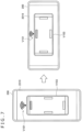
- FIG. 8 is an explanatory diagram for describing an example of the method by which information according to the estimation result of the incoming direction of the wireless signal is fed back by the communication apparatus according to the working example 2.
- FIG. 8 illustrates another example of a case where information is fed back to the user as display information via the display section 2019 .
- FIG. 8 illustrates another example of a case where information indicating the position of the antenna apparatus 220 used for the reception of the wireless signal transmitted from the base station 100 and information indicating the incoming direction of the wireless signal in question are presented.
- display information V 111 and display information V 113 are presented via the display section 2019 .
- the display information V 113 is information for feeding back, of the plurality of antenna apparatuses 220 (communication sections) included in the terminal apparatus 200 , the antenna apparatus 220 used for the reception of the wireless signal to the user.
- icons corresponding to the plurality of antenna apparatuses 220 are presented as the display information V 113 at the positions on the screen of the display section 2019 according to the positions where the antenna apparatuses 220 are held.
- the display information V 111 points to the direction equivalent to the upper side in the figure.
- the icon corresponding, respectively, to the plurality of antenna apparatuses 220 presented as the display information V 113 the icon corresponding to the direction equivalent to the upper side in the figure is highlighted. That is, the example in FIG. 8 illustrates that the wireless signal arrives at the terminal apparatus 200 from the direction equivalent to the upper side in the figure and that the antenna apparatus 220 located on the side of the direction in question is used for the reception of the wireless signal in question.
- FIG. 10 is an explanatory diagram for describing an example of the method by which information according to the estimation result of the incoming direction of the wireless signal is fed back by the communication apparatus according to the working example 4.
- FIG. 10 illustrates yet another example of a case where information is fed back to the user as display information via the display section 2019 .
- the antenna apparatus 220 (communication section) capable of forming the directional beam in the direction of an optical axis of the imaging apparatus that captures the video image of the real space to receive the wireless signal arriving from the direction of the optical axis. That is, it becomes possible for the terminal apparatus 200 in question to receive the wireless signal transmitted from the base station 100 if the user changes the posture of the terminal apparatus 200 in such a manner that the display information V 131 is displayed in the screen of the display section 2019 .
- the terminal apparatus 200 feeds back, to the user, the fact that it is difficult to use the antenna apparatuses 220 covered with the user's hand, by superimposing display information V 145 a and display information V 145 b on the icons associated with the antenna apparatuses 220 in question.
- the method by which the covering of some of the antenna apparatuses 220 with the user's hand is detected is not particularly limited. As a specific example, the covering of some of the antenna apparatuses 220 with the user's hand may be detected by using various sensors such as a contact sensor and a proximity sensor. Also, in a case where the covering of some of the antenna apparatuses 220 with the user's hand is detected, the terminal apparatus 200 may give priority to measurement of the reception sensitivity of the wireless signal by other antenna apparatuses 220 .
- FIG. 13 illustrates an example of a case where the housing 201 of the terminal apparatus 200 is held in such a posture that the long length direction of the housing 201 in question as seen from the user approximately agrees with the lateral direction of the user in question.
- the housing 201 is held in such a manner that the screen of the display section 2019 is in portrait orientation.
- both of the edge portions of the housing 201 in question in the short length direction are gripped by the user's hand.
- FIG. 13 schematically illustrates the state in which the antenna apparatuses 220 each provided in the vicinity of both of the edge portions of the housing 201 in the short length direction are covered with the user's hand. Accordingly, in the example illustrated in FIG. 13 , the terminal apparatus 200 feeds back, to the user, not only the incoming direction of the wireless signal but also the antenna apparatuses 220 having difficulty in receiving the wireless signal because of being covered with the hand.
- the terminal apparatus 200 feeds back, to the user, the incoming direction of the wireless signal by presenting display information V 151 . Also, the terminal apparatus 200 highlights, of the icons presented, respectively, in a manner associated with the plurality of antenna apparatuses 220 , an icon V 153 associated with the antenna apparatus 220 that is used for the reception of the wireless signal. This operation is similar to that described with reference to FIG. 8 .
- the terminal apparatus 200 feeds back, to the user, the fact that it is difficult to use the antenna apparatuses 220 covered with the user's hand, by superimposing display information V 155 a and display information V 155 b on the icons associated with the antenna apparatuses 220 in question.
- the wireless signal arrives from one of the long length directions of the housing 201 (left side in FIG. 14 ), with the housing 201 held in such a posture that the screen of the display section 2019 is in landscape orientation.
- the antenna apparatus 220 used for the reception of the wireless signal (antenna apparatus 220 associated with the highlighted icon V 143 ) to be covered with the hand.
- the terminal apparatus 200 may guide the user in question, by presenting information indicating the position by which the housing 201 is to be gripped or by other ways, in such a manner that the antenna apparatus 220 expected to be used for the reception of the wireless signal is not covered with the user' hand.
- the terminal apparatus 200 may guide the user in such a manner that, of the edge portions of the housing 201 in the long length directions, the edge portion in the direction equivalent to the right side in FIG. 14 is held by the user in question.
- the terminal apparatus 200 may present, to the user, information regarding guidance as to the method by which the housing 201 in question is to be gripped, on the basis of the estimation result of the posture in question.
- a trigger such as activation of content
- the terminal apparatus 200 may present, to the user, information regarding guidance as to the method by which the housing 201 in question is to be gripped, on the basis of the estimation result of the posture in question.
- the housing 201 is held in such a manner that the screen of the display section 2019 is in landscape orientation.
- the terminal apparatus 200 may present, to the user, information indicating the method by which the housing 201 is to be gripped (e.g., the position at which the housing 201 is to be gripped), on the basis of the estimation result of the posture of the housing 201 in question and the estimation result of the incoming direction of the wireless signal in such a manner that the incoming direction of the wireless signal is not covered with the user's hand.
- information indicating the method by which the housing 201 is to be gripped e.g., the position at which the housing 201 is to be gripped
- a plurality of options of information may be presented as information according to the estimation result of the incoming direction of the wireless signal. Also, at this time, all the options of information may be presented. Alternatively, some of the options of information (e.g., predetermined number of options in decreasing order of reception sensitivity) may be presented. Also, when the plurality of options of information are presented, the options of information with the higher reception sensitivity may be highlighted more. Naturally, in a case where there are two or more options, information of only one of the options may be presented. In this case, it is only necessary to identify one of the options from among the plurality of options on the basis of the predetermined condition and present information regarding the identified option in question. As a specific example, the option with the higher reception sensitivity may be identified as a target.
- the plurality of communication sections e.g., antenna apparatuses 220
- pieces of information each associated with the plurality of communication sections in question may be highlighted.
- the manner in which the pieces of information each corresponding to the plurality of communication sections in question are presented may be controlled according to an extent to which each of the plurality of communication sections used for the reception of the wireless signal contributes to the reception in question.
- the piece of information corresponding to the communication section that contributes more to the reception in question may be highlighted.
- an occasion related to the estimation of the incoming direction of the wireless signal and the presentation of information according to the estimation result in question is not particularly limited.
- the incoming direction of the wireless signal may be estimated in real time.
- information according to the estimation result in question may be presented in real time in conjunction with the estimation of the incoming direction of the wireless signal, or the information may be presented in response to the predetermined trigger.
- the estimation of the incoming direction of the wireless signal and the presentation of information according to the estimation result in question may be conducted in response to the predetermined trigger.
- the estimation of the incoming direction of the wireless signal and the presentation of information according to the estimation result in question may be conducted by using the change in question in the detection result as the trigger.
- the method by which the incoming direction of the wireless signal is estimated may be changed as appropriate in consideration of a use case.
- the estimation of the incoming direction of the wireless signal may be conducted on the basis of the reception result of the wireless signal at that time.
- information according to the reception result of the wireless signal may be accumulated sequentially, thus statistically estimating the incoming direction of the wireless signal in question on the basis of a tallying result of the information in question for a predetermined period of time.
- information types and the method by which information is presented are not particularly limited as long as it is possible to feed back desired information to the user.
- information according to the estimation result of the incoming direction of the wireless signal may be presented via an acoustic output section such as a speaker as a voice or acoustics.
- information according to the estimation result in question may be presented as a tactile sensation or a force sensation by vibrating the vibration section such as an actuator, according to the estimation result of the incoming direction of the wireless signal.
- FIG. 15 is a functional block diagram illustrating an example of the hardware configuration of the information processing apparatus included in the system according to an embodiment of the present disclosure.
- An information processing apparatus 900 included in an imaging system primarily includes a CPU 901 , a ROM 902 , and a RAM 903 . Also, the information processing apparatus 900 further includes a host bus 907 , a bridge 909 , an external bus 911 , an interface 913 , an input apparatus 915 , an output apparatus 917 , a storage apparatus 919 , a drive 921 , a connection port 923 , and a communication apparatus 925 .
- the CPU 901 functions as an arithmetic processing apparatus and a control apparatus and controls the overall or partial operation in the information processing apparatus 900 according to various programs recorded in the ROM 902 , the RAM 903 , the storage apparatus 919 , or a removable recording medium 927 .
- the ROM 902 stores the programs and arithmetic parameters used by the CPU 901 .
- the RAM 903 temporarily stores the programs used by the CPU 901 , parameters that change as appropriate during execution of the programs, and the like. These are connected to each other by the host bus 907 that includes internal buses such as CPU buses.
- the host bus 907 is connected to the external bus 911 such as a PCI (Peripheral Component Interconnect/Interface) bus via the bridge 909 . Also, the input apparatus 915 , the output apparatus 917 , the storage apparatus 919 , the drive 921 , the connection port 923 , and the communication apparatus 925 are connected to the external bus 911 via the interface 913 .
- PCI Peripheral Component Interconnect/Interface
- the input apparatus 915 is manipulating means, such as a mouse, a keyboard, a touch panel, a button, a switch, a lever, and a pedal, manipulated by the user.
- the input apparatus 915 may be, for example, remote control means (what is called a remote control) using infrared rays or other radio waves or external connection equipment 929 such as a mobile phone or a PDA corresponding to the manipulation of the information processing apparatus 900 .
- the input apparatus 915 includes, for example, an input control circuit that generates an input signal on the basis of information input by the user by using the above manipulating means and outputs the signal to the CPU 901 .
- the user of the information processing apparatus 900 can input various pieces of data to the information processing apparatus 900 and instruct that processing an operation be conducted by manipulating the input apparatus 915 .
- the output apparatus 917 includes apparatuses that are able to visually or audibly inform the user of acquired information.
- Such apparatuses are display apparatuses such as a CRT display apparatus, a liquid crystal display apparatus, a plasma display apparatus, an EL display apparatus, and lamps, audio output apparatuses such as a speaker and a headphone, and printer apparatuses.
- the output apparatus 917 outputs the result acquired by various processing tasks conducted by the information processing apparatus 900 .
- the display apparatus displays the result acquired by various processing tasks conducted by the information processing apparatus 900 in the form of a text or an image.
- the audio output apparatus converts an audio signal including reproduced sound data, acoustic data, or the like into an analog signal and outputs the analog signal.
- the output section 2009 described earlier with reference to FIG. 2 can be realized, for example, by the output apparatus 917 .
- the storage apparatus 919 is an apparatus for storing data configured as an example of the storage section of the information processing apparatus 900 .
- the storage apparatus 919 includes, for example, a magnetic storage device such as an HDD (Hard Disk Drive), a semiconductor storage device, an optical storage device, a magneto-optical storage section device, or the like.
- the storage apparatus 919 stores the programs executed by the CPU 901 , various types of data, and the like. It should be noted that the storage section 2007 described earlier with reference to FIG. 2 can be realized, for example, by the storage apparatus 919 .
- the drive 921 is a reader/writer for a recording medium and incorporated in or attached externally to the information processing apparatus 900 .
- the drive 921 reads out information recorded in the attached removable recording medium 927 such as a magnetic disk, an optical disc, a magneto-optical disk, or a semiconductor memory and outputs the information to the RAM 903 .
- the drive 921 can write a record to the attached removable recording medium 927 such as a magnetic disk, an optical disc, a magneto-optical disk, or a semiconductor memory.
- the removable recording medium 927 is, for example, DVD media, HD-DVD media, Blu-ray (registered trademark) media, or the like.
- the removable recording medium 927 may be a CompactFlash (CF) (registered trademark), a flash memory, an SD memory card (Secure Digital memory card), or the like. Also, the removable recording medium 927 may be an IC card (Integrated Circuit card) having a non-contact IC chip, electronic equipment, or the like.
- CF CompactFlash
- SD memory card Secure Digital memory card
- the removable recording medium 927 may be an IC card (Integrated Circuit card) having a non-contact IC chip, electronic equipment, or the like.
- the connection port 923 is a port for direct connection to the information processing apparatus 900 .
- Examples of the connection port 923 are USB (Universal Serial Bus) port, IEEE1394 port, and SCSI (Small Computer System Interface) port.
- Other examples of the connection port 923 are an RS-232C port, an optical audio terminal, and an HDMI (registered trademark) (High-Definition Multimedia Interface) port.
- the information processing apparatus 900 can directly acquire various pieces of data from the external connection equipment 929 or provide various types of data to the external connection equipment 929 by connecting the external connection equipment 929 to the connection port 923 .
- the communication apparatus 925 is a communication interface that includes a communication device for connection to a communication network 931 , for example.
- the communication apparatus 925 is, for example, a communication card for a wired or wireless LAN (Local Area Network), Bluetooth (registered trademark), a WUSB (Wireless USB), or the like.
- the communication apparatus 925 may be a router for optical communication, a router for an ADSL (Asymmetric Digital Subscriber Line), a modem for various types of communication, or the like.
- This communication apparatus 925 can transmit and receive a signal and the like to and from the Internet or another communication equipment in conformity with a predetermined protocol such as a TCP/IP.
- the communication network 931 connected to the communication apparatus 925 includes a network connected in a wired or wireless manner or the like and may be, for example, the Internet, a home LAN, infrared communication, radio wave communication, satellite communication, or the like. It should be noted that the wireless communication section 2003 described earlier with reference to FIG. 2 can be realized, for example, by the communication apparatus 925 .
- each of the above constituents may be configured by using a general-purpose member or include hardware tailored to the functions of the constituent. Accordingly, it is possible to change the hardware configuration to be used as appropriate according to a technical level at the time when the present embodiment is carried out. It should be noted that, although not illustrated in FIG. 15 , various constituents corresponding to the information processing apparatus 900 included in the imaging system according to the present embodiment are naturally provided.
- the above computer programs may be delivered, for example, via the network without using the recording medium.
- the number of computers for executing the computer programs in question is not particularly limited.
- the computer programs in question may be executed in coordination between the plurality of computers (e.g., plurality of servers). It should be noted that a single computer or a plurality of computers working in a coordinated manner will be also referred to as a “computer system.”
- the communication apparatus includes the one or more communication sections, the estimation section, and the output control section.
- Each of the communication sections communicates with other communication apparatuses via the wireless communication channel.
- the estimation section estimates, on the basis of the reception result of the wireless signal by at least some of the one or more communication sections, the incoming direction of the wireless signal.
- the output control section exercises control in such a manner that the notification information according to the estimation result of the incoming direction is presented via the output section.
- the communication apparatus even in the situation where the wireless signals such as millimeter waves that have the extremely high straight traveling property and can decline significantly in radio wave strength as a result of being shielded by a shield is used for communication, it is possible to feed back, to the user, the presence of the wireless signal in question in a more preferred manner.
- the plurality of communication sections for receiving the wireless signal are provided
- the terminal apparatus 200 guide the user in such a manner as to change the posture of the housing 201 and estimate the incoming direction of the wireless signal when the communication section becomes able to receive the wireless signal on the basis of the detection result of the posture of the housing 201 at that time and the reception result of the wireless signal in question.
- an advantageous effect described in the present specification is explanatory or illustrative and not restrictive. That is, the technology according to the present disclosure can provide other advantageous effects apparent to a person skilled in the art from the description of the present specification together with or in place of the above advantageous effect.
- a communication apparatus including:
- An information processing apparatus including:
- An information processing method including, by a computer:
Landscapes
- Engineering & Computer Science (AREA)
- Computer Networks & Wireless Communication (AREA)
- Signal Processing (AREA)
- Human Computer Interaction (AREA)
- Theoretical Computer Science (AREA)
- Physics & Mathematics (AREA)
- Environmental & Geological Engineering (AREA)
- General Engineering & Computer Science (AREA)
- General Physics & Mathematics (AREA)
- Software Systems (AREA)
- Computer Hardware Design (AREA)
- Computer Graphics (AREA)
- Mobile Radio Communication Systems (AREA)
- Quality & Reliability (AREA)
- Electromagnetism (AREA)
- Telephone Function (AREA)
Abstract
Description
-
- Samsung, SK Telecom, KT Corporation, LG Uplus, NTT DOCOMO, INC., “On band definition for 26.5-29.5 GHz,” R4-1704770, 3GPP TSG RAN WG4 Meeting #83, Hangzhou, China 15-19 May 2017
-
- 1. Schematic configuration
- 1.1. Example of the system configuration
- 1.2. Configuration example of the terminal apparatus
- 2. Examination regarding communication assuming the use of millimeter waves
- 3. Technical features
- 3.1. Schematic configuration of the communication apparatus
- 3.2. Schematic operation
- 3.3. Working examples
- 4. Hardware configuration
- 5. Conclusion
- 1. Schematic configuration
-
- one or more communication sections each configured to communicate with other communication apparatuses via a wireless communication channel;
- an estimation section configured to estimate, on the basis of reception results of a wireless signal by at least some of the one or more communication sections, an incoming direction of the wireless signal; and
- an output control section configured to exercise control in such a manner that notification information according to an estimation result of the incoming direction is presented via an output section.
(2)
-
- the output control section exercises control in such a manner that information indicating the incoming direction is presented as the notification information.
(3)
- the output control section exercises control in such a manner that information indicating the incoming direction is presented as the notification information.
-
- the output control section exercises control in such a manner that information indicating the incoming direction is presented in a manner superimposed on a real space.
(4)
- the output control section exercises control in such a manner that information indicating the incoming direction is presented in a manner superimposed on a real space.
-
- a plurality of the communication sections; and
- a housing configured to support the plurality of communication sections in such a manner that the plurality of communication sections receive, respectively, the wireless signals arriving from relatively different directions, in which
- the estimation section estimates, on the basis of reception results of the wireless signal by at least some of the plurality of communication sections, the incoming direction of the wireless signal in question.
(5)
-
- the estimation section identifies, on the basis of the reception results of the wireless signal by at least some of the communication sections, the communication section of the at least some of the communication sections that has higher reception sensitivity, and
- the output control section exercises control in such a manner that information according to the identification result of the communication section having the higher reception sensitivity is presented as the notification information.
(6)
-
- the output control section exercises control in such a manner that a position where the identified communication section having the higher reception sensitivity is supported is presented as the notification information.
(7)
- the output control section exercises control in such a manner that a position where the identified communication section having the higher reception sensitivity is supported is presented as the notification information.
-
- the output control section exercises control in such a manner that information regarding guidance as to a method by which the housing is to be gripped according to the identification result of the communication section having the higher reception sensitivity is presented as the notification information.
(8)
- the output control section exercises control in such a manner that information regarding guidance as to a method by which the housing is to be gripped according to the identification result of the communication section having the higher reception sensitivity is presented as the notification information.
-
- the output control section exercises control in such a manner that the position by which the housing is to be gripped is presented as information regarding the guidance as to the method by which the housing in question is to be gripped.
(9)
- the output control section exercises control in such a manner that the position by which the housing is to be gripped is presented as information regarding the guidance as to the method by which the housing in question is to be gripped.
-
- the output control section exercises control in such a manner that information regarding the guidance as to the method by which the housing is to be gripped according to a posture of the housing in question is presented.
(10)
- the output control section exercises control in such a manner that information regarding the guidance as to the method by which the housing is to be gripped according to a posture of the housing in question is presented.
-
- the communication section is configured in such a manner as to be able to control a directional beam pattern related to the reception of the wireless signal, and
- the estimation section estimates, on the basis of identification information associated with the directional beam used by the communication section for the reception of the wireless signal, the incoming direction of the wireless signal in question.
(11)
-
- the wireless signal is a downlink signal transmitted by a base station by selectively switching between a plurality of beam patterns.
(12)
- the wireless signal is a downlink signal transmitted by a base station by selectively switching between a plurality of beam patterns.
-
- an estimation section configured to estimate, on the basis of reception results of a wireless signal by at least some of one or more communication sections each of which communicates with other communication apparatuses via a wireless communication channel, an incoming direction of the wireless signal in question; and
- an output control section configured to exercise control in such a manner that notification information according to an estimation result of the incoming direction is presented via an output section.
(13)
-
- estimating, on the basis of reception results of a wireless signal by at least some of one or more communication sections each of which communicates with other communication apparatuses via a wireless communication channel, an incoming direction of the wireless signal in question; and exercising control in such a manner that notification information according to an estimation result of the incoming direction is presented via an output section.
-
- 1: System
- 100: Base station
- 200: Terminal apparatus
- 201: Housing
- 220: Antenna apparatus
- 221: Substrate
- 223: Antenna component
- 225: Control circuit
- 2001: Antenna section
- 2003: Wireless communication section
- 2005: Control section
- 2007: Storage section
- 2009: Output section
- 2011: Detection section
- 2013: Communication control section
- 2015: Estimation section
- 2017: Output control section
- 2019: Display section
Claims (13)
Applications Claiming Priority (1)
| Application Number | Priority Date | Filing Date | Title |
|---|---|---|---|
| PCT/JP2019/003449 WO2020157930A1 (en) | 2019-01-31 | 2019-01-31 | Communication device, information processing device, and information processing method |
Publications (2)
| Publication Number | Publication Date |
|---|---|
| US20220094775A1 US20220094775A1 (en) | 2022-03-24 |
| US12219084B2 true US12219084B2 (en) | 2025-02-04 |
Family
ID=71840387
Family Applications (1)
| Application Number | Title | Priority Date | Filing Date |
|---|---|---|---|
| US17/425,003 Active 2040-09-06 US12219084B2 (en) | 2019-01-31 | 2019-01-31 | Communication apparatus, information processing apparatus, and information processing method to feed back presence of a wireless signal |
Country Status (5)
| Country | Link |
|---|---|
| US (1) | US12219084B2 (en) |
| EP (1) | EP3920515B1 (en) |
| JP (1) | JP7405101B2 (en) |
| CN (1) | CN113330725B (en) |
| WO (1) | WO2020157930A1 (en) |
Families Citing this family (4)
| Publication number | Priority date | Publication date | Assignee | Title |
|---|---|---|---|---|
| EP3788775B1 (en) * | 2018-05-02 | 2021-09-22 | Telefonaktiebolaget LM Ericsson (publ) | User equipment, method by a user equipment, and network node |
| TWI737337B (en) * | 2020-06-05 | 2021-08-21 | 啟碁科技股份有限公司 | Method for determining position of base station and associated electronic device |
| CN117378152A (en) * | 2021-05-25 | 2024-01-09 | 夏普株式会社 | Communication terminal and control method |
| WO2024048361A1 (en) * | 2022-09-02 | 2024-03-07 | ソニーグループ株式会社 | Information processing device and information processing method |
Citations (12)
| Publication number | Priority date | Publication date | Assignee | Title |
|---|---|---|---|---|
| KR20000042765A (en) | 1998-12-26 | 2000-07-15 | 윤종용 | Method for displaying direction of optimum receiving sensitivity in cellular phone |
| WO2012042851A1 (en) | 2010-09-30 | 2012-04-05 | パナソニック株式会社 | Wireless communication device and wireless communication method |
| JP2012248935A (en) | 2011-05-25 | 2012-12-13 | Nec Corp | Radio communication device and control method therefor |
| WO2013077197A1 (en) | 2011-11-24 | 2013-05-30 | 株式会社 エヌ・ティ・ティ・ドコモ | Mobile communication terminal, mobile communication method, mobile communication program, and storage medium |
| EP2747193A1 (en) | 2012-12-19 | 2014-06-25 | BlackBerry Limited | Method and system for antenna alignment |
| JP2014239393A (en) | 2013-06-10 | 2014-12-18 | 株式会社Nttドコモ | Wireless tag search method and device therefor |
| JP2016092451A (en) | 2014-10-29 | 2016-05-23 | 京セラ株式会社 | mobile phone |
| US20160278044A1 (en) * | 2015-03-18 | 2016-09-22 | Panasonic Intellectual Property Management Co., Ltd. | Wireless communicating apparatus |
| WO2017169013A1 (en) | 2016-03-30 | 2017-10-05 | シャープ株式会社 | Terminal device, server device, information processing method, and program |
| WO2017169010A1 (en) | 2016-03-30 | 2017-10-05 | シャープ株式会社 | Terminal device, communication method, and program |
| WO2017169016A1 (en) | 2016-03-30 | 2017-10-05 | シャープ株式会社 | Terminal device, communication method, and program |
| WO2018143390A1 (en) | 2017-02-03 | 2018-08-09 | 株式会社Nttドコモ | User terminal and wireless communication method |
-
2019
- 2019-01-31 CN CN201980090054.2A patent/CN113330725B/en active Active
- 2019-01-31 EP EP19912397.7A patent/EP3920515B1/en active Active
- 2019-01-31 JP JP2020569291A patent/JP7405101B2/en active Active
- 2019-01-31 WO PCT/JP2019/003449 patent/WO2020157930A1/en not_active Ceased
- 2019-01-31 US US17/425,003 patent/US12219084B2/en active Active
Patent Citations (19)
| Publication number | Priority date | Publication date | Assignee | Title |
|---|---|---|---|---|
| KR20000042765A (en) | 1998-12-26 | 2000-07-15 | 윤종용 | Method for displaying direction of optimum receiving sensitivity in cellular phone |
| US20130189929A1 (en) | 2010-09-30 | 2013-07-25 | Panasonic Corporation | Wireless communication device and wireless communication method |
| WO2012042851A1 (en) | 2010-09-30 | 2012-04-05 | パナソニック株式会社 | Wireless communication device and wireless communication method |
| JP2012078172A (en) | 2010-09-30 | 2012-04-19 | Panasonic Corp | Radio communication device |
| JP2012248935A (en) | 2011-05-25 | 2012-12-13 | Nec Corp | Radio communication device and control method therefor |
| US20140349715A1 (en) | 2011-11-24 | 2014-11-27 | Ntt Docomo, Inc. | Mobile communication terminal, mobile communication method, mobile communication program and recording medium |
| EP2785023A1 (en) | 2011-11-24 | 2014-10-01 | Ntt Docomo, Inc. | Mobile communication terminal, mobile communication method, mobile communication program, and storage medium |
| WO2013077197A1 (en) | 2011-11-24 | 2013-05-30 | 株式会社 エヌ・ティ・ティ・ドコモ | Mobile communication terminal, mobile communication method, mobile communication program, and storage medium |
| JP5647595B2 (en) | 2011-11-24 | 2015-01-07 | 株式会社Nttドコモ | Mobile communication terminal, mobile communication method, and mobile communication program |
| EP2747193A1 (en) | 2012-12-19 | 2014-06-25 | BlackBerry Limited | Method and system for antenna alignment |
| JP6059607B2 (en) | 2013-06-10 | 2017-01-11 | 株式会社Nttドコモ | Wireless tag search method and apparatus |
| JP2014239393A (en) | 2013-06-10 | 2014-12-18 | 株式会社Nttドコモ | Wireless tag search method and device therefor |
| JP2016092451A (en) | 2014-10-29 | 2016-05-23 | 京セラ株式会社 | mobile phone |
| US20160278044A1 (en) * | 2015-03-18 | 2016-09-22 | Panasonic Intellectual Property Management Co., Ltd. | Wireless communicating apparatus |
| WO2017169013A1 (en) | 2016-03-30 | 2017-10-05 | シャープ株式会社 | Terminal device, server device, information processing method, and program |
| WO2017169010A1 (en) | 2016-03-30 | 2017-10-05 | シャープ株式会社 | Terminal device, communication method, and program |
| WO2017169016A1 (en) | 2016-03-30 | 2017-10-05 | シャープ株式会社 | Terminal device, communication method, and program |
| JP6584034B2 (en) | 2016-03-30 | 2019-10-02 | シャープ株式会社 | Terminal device, communication method and program |
| WO2018143390A1 (en) | 2017-02-03 | 2018-08-09 | 株式会社Nttドコモ | User terminal and wireless communication method |
Non-Patent Citations (4)
| Title |
|---|
| European Search Report of EP Application No. 19912397.7, issued on Jan. 4, 2022, 07 pages. |
| International Search Report and Written Opinion of PCT Application No. PCT/JP2019/003449, issued on Mar. 26, 2019, 08 pages of ISRWO. |
| Machine Translation of WO2017/169013 (Year: 2017). * |
| Machine Translation of WO2017/169016 (Year: 2017). * |
Also Published As
| Publication number | Publication date |
|---|---|
| EP3920515A1 (en) | 2021-12-08 |
| EP3920515B1 (en) | 2024-08-14 |
| JP7405101B2 (en) | 2023-12-26 |
| US20220094775A1 (en) | 2022-03-24 |
| JPWO2020157930A1 (en) | 2021-12-02 |
| WO2020157930A1 (en) | 2020-08-06 |
| CN113330725B (en) | 2023-05-23 |
| EP3920515A4 (en) | 2022-01-26 |
| CN113330725A (en) | 2021-08-31 |
Similar Documents
| Publication | Publication Date | Title |
|---|---|---|
| US12490291B2 (en) | Methods, architectures, apparatuses and systems for extended reality-assisted radio resource management | |
| US12219084B2 (en) | Communication apparatus, information processing apparatus, and information processing method to feed back presence of a wireless signal | |
| US11894604B2 (en) | Communication apparatus | |
| TWI767084B (en) | Communication device, communication method, and program | |
| JP6769431B2 (en) | apparatus | |
| US11528647B2 (en) | Device and method for measuring a channel state | |
| JP6634982B2 (en) | Terminal device, base station, method and recording medium | |
| US10944449B2 (en) | Apparatus and method in wireless communication system, and computer readable storage medium | |
| US20190215134A1 (en) | Apparatus and method | |
| KR102332909B1 (en) | Terminal device, base station, method and recording medium | |
| CN110958042A (en) | Network side device, user equipment, wireless communication method and storage medium | |
| WO2015170651A1 (en) | Device | |
| CN110166146A (en) | A kind of power-sensing circuit and terminal | |
| JP7127648B2 (en) | Communication device and communication method | |
| JPWO2015182292A1 (en) | apparatus | |
| JP6888663B2 (en) | Terminal equipment, base stations, methods and recording media | |
| CN113853751B (en) | Electronic device, distributed unit device, wireless communication method and storage medium | |
| JP2011151670A (en) | Radio communication method and radio communication system | |
| US12192786B2 (en) | Diagnosis of operation of plural communicating units | |
| KR20160067393A (en) | Apparatus for controlling push service | |
| CN117376938A (en) | Antenna management method, equipment and communication system | |
| CN119497192A (en) | A communication method and corresponding device | |
| KR20170136360A (en) | Wireless signal receiving module |
Legal Events
| Date | Code | Title | Description |
|---|---|---|---|
| AS | Assignment |
Owner name: SONY GROUP CORPORATION, JAPAN Free format text: ASSIGNMENT OF ASSIGNORS INTEREST;ASSIGNOR:SUZUKI, YUICHIRO;REEL/FRAME:056944/0832 Effective date: 20210609 |
|
| FEPP | Fee payment procedure |
Free format text: ENTITY STATUS SET TO UNDISCOUNTED (ORIGINAL EVENT CODE: BIG.); ENTITY STATUS OF PATENT OWNER: LARGE ENTITY |
|
| STPP | Information on status: patent application and granting procedure in general |
Free format text: DOCKETED NEW CASE - READY FOR EXAMINATION |
|
| STPP | Information on status: patent application and granting procedure in general |
Free format text: NON FINAL ACTION MAILED |
|
| STPP | Information on status: patent application and granting procedure in general |
Free format text: RESPONSE TO NON-FINAL OFFICE ACTION ENTERED AND FORWARDED TO EXAMINER |
|
| STPP | Information on status: patent application and granting procedure in general |
Free format text: FINAL REJECTION MAILED |
|
| STPP | Information on status: patent application and granting procedure in general |
Free format text: ADVISORY ACTION MAILED |
|
| STPP | Information on status: patent application and granting procedure in general |
Free format text: DOCKETED NEW CASE - READY FOR EXAMINATION |
|
| STPP | Information on status: patent application and granting procedure in general |
Free format text: NOTICE OF ALLOWANCE MAILED -- APPLICATION RECEIVED IN OFFICE OF PUBLICATIONS |
|
| STPP | Information on status: patent application and granting procedure in general |
Free format text: PUBLICATIONS -- ISSUE FEE PAYMENT VERIFIED |
|
| STCF | Information on status: patent grant |
Free format text: PATENTED CASE |