US12196080B2 - Drilling device for geotechnical engineering investigation - Google Patents
Drilling device for geotechnical engineering investigation Download PDFInfo
- Publication number
- US12196080B2 US12196080B2 US18/331,254 US202318331254A US12196080B2 US 12196080 B2 US12196080 B2 US 12196080B2 US 202318331254 A US202318331254 A US 202318331254A US 12196080 B2 US12196080 B2 US 12196080B2
- Authority
- US
- United States
- Prior art keywords
- supporting
- seat
- ring seat
- rotatably connected
- supporting ring
- Prior art date
- Legal status (The legal status is an assumption and is not a legal conclusion. Google has not performed a legal analysis and makes no representation as to the accuracy of the status listed.)
- Active, expires
Links
- 238000005553 drilling Methods 0.000 title claims abstract description 71
- 238000011835 investigation Methods 0.000 title claims abstract description 29
- 230000008093 supporting effect Effects 0.000 claims abstract description 167
- 230000007246 mechanism Effects 0.000 claims abstract description 42
- XLYOFNOQVPJJNP-UHFFFAOYSA-N water Substances O XLYOFNOQVPJJNP-UHFFFAOYSA-N 0.000 claims description 21
- 230000003139 buffering effect Effects 0.000 claims description 20
- 239000011435 rock Substances 0.000 claims description 8
- 238000005086 pumping Methods 0.000 claims description 5
- 238000013016 damping Methods 0.000 claims description 4
- 239000007788 liquid Substances 0.000 claims description 4
- 238000007599 discharging Methods 0.000 claims description 3
- 238000010586 diagram Methods 0.000 description 7
- 238000000034 method Methods 0.000 description 7
- 238000010276 construction Methods 0.000 description 5
- 230000008569 process Effects 0.000 description 5
- 239000002689 soil Substances 0.000 description 4
- 230000003044 adaptive effect Effects 0.000 description 1
- 230000009286 beneficial effect Effects 0.000 description 1
- 230000008859 change Effects 0.000 description 1
- 238000013461 design Methods 0.000 description 1
- 230000000694 effects Effects 0.000 description 1
- 238000005516 engineering process Methods 0.000 description 1
- 230000007613 environmental effect Effects 0.000 description 1
- 230000006872 improvement Effects 0.000 description 1
- 238000012986 modification Methods 0.000 description 1
- 230000004048 modification Effects 0.000 description 1
- 230000002787 reinforcement Effects 0.000 description 1
- 238000006467 substitution reaction Methods 0.000 description 1
- 238000012360 testing method Methods 0.000 description 1
Images


Classifications
-
- E—FIXED CONSTRUCTIONS
- E21—EARTH OR ROCK DRILLING; MINING
- E21B—EARTH OR ROCK DRILLING; OBTAINING OIL, GAS, WATER, SOLUBLE OR MELTABLE MATERIALS OR A SLURRY OF MINERALS FROM WELLS
- E21B7/00—Special methods or apparatus for drilling
- E21B7/04—Directional drilling
-
- E—FIXED CONSTRUCTIONS
- E21—EARTH OR ROCK DRILLING; MINING
- E21B—EARTH OR ROCK DRILLING; OBTAINING OIL, GAS, WATER, SOLUBLE OR MELTABLE MATERIALS OR A SLURRY OF MINERALS FROM WELLS
- E21B7/00—Special methods or apparatus for drilling
- E21B7/02—Drilling rigs characterised by means for land transport with their own drive, e.g. skid mounting or wheel mounting
- E21B7/027—Drills for drilling shallow holes, e.g. for taking soil samples or for drilling postholes
-
- E—FIXED CONSTRUCTIONS
- E21—EARTH OR ROCK DRILLING; MINING
- E21B—EARTH OR ROCK DRILLING; OBTAINING OIL, GAS, WATER, SOLUBLE OR MELTABLE MATERIALS OR A SLURRY OF MINERALS FROM WELLS
- E21B11/00—Other drilling tools
- E21B11/005—Hand operated drilling tools
-
- E—FIXED CONSTRUCTIONS
- E21—EARTH OR ROCK DRILLING; MINING
- E21B—EARTH OR ROCK DRILLING; OBTAINING OIL, GAS, WATER, SOLUBLE OR MELTABLE MATERIALS OR A SLURRY OF MINERALS FROM WELLS
- E21B15/00—Supports for the drilling machine, e.g. derricks or masts
- E21B15/04—Supports for the drilling machine, e.g. derricks or masts specially adapted for directional drilling, e.g. slant hole rigs
-
- E—FIXED CONSTRUCTIONS
- E21—EARTH OR ROCK DRILLING; MINING
- E21B—EARTH OR ROCK DRILLING; OBTAINING OIL, GAS, WATER, SOLUBLE OR MELTABLE MATERIALS OR A SLURRY OF MINERALS FROM WELLS
- E21B17/00—Drilling rods or pipes; Flexible drill strings; Kellies; Drill collars; Sucker rods; Cables; Casings; Tubings
- E21B17/22—Rods or pipes with helical structure
-
- F—MECHANICAL ENGINEERING; LIGHTING; HEATING; WEAPONS; BLASTING
- F16—ENGINEERING ELEMENTS AND UNITS; GENERAL MEASURES FOR PRODUCING AND MAINTAINING EFFECTIVE FUNCTIONING OF MACHINES OR INSTALLATIONS; THERMAL INSULATION IN GENERAL
- F16F—SPRINGS; SHOCK-ABSORBERS; MEANS FOR DAMPING VIBRATION
- F16F15/00—Suppression of vibrations in systems; Means or arrangements for avoiding or reducing out-of-balance forces, e.g. due to motion
- F16F15/02—Suppression of vibrations of non-rotating, e.g. reciprocating systems; Suppression of vibrations of rotating systems by use of members not moving with the rotating systems
- F16F15/023—Suppression of vibrations of non-rotating, e.g. reciprocating systems; Suppression of vibrations of rotating systems by use of members not moving with the rotating systems using fluid means
Definitions
- the application relates to the technical field of geotechnical engineering investigation, and in particular to a drilling device for geotechnical engineering investigation.
- Geotechnical engineering investigation refers to the activity of identifying, analyzing and evaluating the geological and environmental characteristics and geotechnical engineering conditions of the construction site and compiling investigation documents according to the requirements of construction projects.
- Main purposes of geotechnical engineering investigation are to investigate, analyze and judge the construction site by testing means and methods, to study the geological conditions of various engineering buildings and the influence of construction on the natural geological environment, to study the measures to ensure the strength and stability of foundation and prevent the foundation from impermissible deformation when the foundation, foundation structure and superstructure work jointly, and to improve the bearing capacity of foundation, and provide the engineering address and geotechnical information needed for foundation design and construction and foundation reinforcement when necessary.
- the existing drilling devices such as a drilling device for geotechnical investigation and drilling technology with publication number of CN113738267A, basically limit the drill pipe in the vertical direction, so that a stable drilling state is maintained.
- this drilling device cannot work and has a small range of application.
- the objective of the application is to provide a drilling device for geotechnical engineering investigation, and the drilling device for geotechnical engineering investigation is able to realize multi-angle position limitation of a drill pipe and limit the drill pipe at a designated drilling position at the same time, and is applicable for various drilling situations, wide in application range and convenient to popularize.
- the application adopts the following technical scheme.
- a drilling device for geotechnical engineering investigation includes an outer supporting ring seat, where a center of the outer supporting ring seat is rotatably connected with a middle supporting ring seat through a first supporting shaft rod; a center of the middle supporting ring seat is rotatably connected with an inner supporting ring seat through a second supporting shaft rod; the first supporting shaft rod and the second supporting shaft rod are vertically crossed; a second rotating motor is fixedly installed at one end of the first supporting shaft rod on an outer surface of the outer supporting ring seat; a pow output end of the second rotating motor is fixedly connected with the first supporting shaft rod, an other end of the first supporting shaft rod is provided with a first locking mechanism for position limitation; a first rotating motor is fixedly installed at one end of the second supporting shaft rod on an outer surface of the middle supporting ring seat, a power output end of the first rotating motor is fixedly connected with the second supporting shaft rod, and an other end of the second supporting shaft rod is also provided with a second locking mechanism for position limitation.
- a drill pipe limit seat is fixedly installed right above the inner supporting ring seat through a bracket, a drilling drive device is arranged right above the drill pipe limit seat, and a connecting support seat is fixedly installed at a power output end of the drilling drive device.
- a drill pipe is fixedly installed at a bottom end of the connecting support seat, a bottom end of the drill pipe is rotatably connected inside the drill pipe limit seat, a drainage mechanism for discharging liquid inside rocks is arranged inside the drill pipe.
- a buffering mechanism for buffering and supporting the drilling drive device is arranged between the connecting support seat and the outer supporting ring seat, and a bottom surface of the outer supporting ring seat is provided with a bottom supporting mechanism fixedly connected with a ground.
- the buffering mechanism includes side supporting arms fixedly welded to the outer surface of the outer supporting ring seat and second universal ball shafts rotatably connected to an outer surface of the connecting support seat; a top surface of each of the side supporting arms is provided with a chute; a slider is slidably connected inside the chute; a top surface of the slider is rotatably connected with a first universal ball shaft; a supporting hydraulic rod is arranged between the first universal ball shaft and corresponding one of the second universal ball shafts; and one end of the supporting hydraulic rod is rotatably connected with the first universal ball shaft and an other end of the supporting hydraulic rod is rotatably connected with the corresponding one of the second universal ball shafts.
- the side supporting arms are provided at least four and are uniformly circumferentially arrayed on the outer surface of the outer supporting ring seat, and a number of the second universal ball shafts is the same as that of the side supporting arms, and positions of the second universal ball shafts and the corresponding side supporting arms are matched.
- a damping sliding shaft is arranged between the slider and the chute.
- the bottom supporting mechanism includes mounting support seats arranged on a bottom surfaces of each joint of the each of the side supporting arms and the outer supporting ring seat, where a bottom end of each of the mounting support seats is rotatably connected with a movable leg, a bottom end of the movable leg are rotatably connected with a grounding leg, and a bottom surface of the grounding leg is provided with a fixing nail.
- a top connecting seat is fixedly welded at one end of a bottom surface of the each of the side supporting arms away from the inner supporting ring seat
- a bottom connecting seat is fixedly welded at a center of a top surface of the movable leg
- a buffering hydraulic rod is arranged between the bottom connecting seat and the top connecting seat, where one end of the buffering hydraulic rod is rotatably connected to the bottom connecting seat, and an other end of the buffering hydraulic rod is rotatably connected to the top connecting seat.
- the first locking mechanism and the second locking mechanism both include supporting shells fixedly installed on the outer surface of the outer supporting ring seat and an outer surface of the middle supporting ring seat; brake gears are arranged in the supporting shells; the brake gears are fixedly sleeved ends of the first supporting shaft rod and the second supporting shaft rod respectively; a brake strut is rotatably connected at one corner of a top end of the each of the supporting shells; a brake chuck is arranged on a bottom surface of one end of the brake strut adjacent to a top surface of each of the brake gears; a brake cylinder is fixedly installed at one end of the each of the supporting shells adjacent to a rotating shaft of the brake strut; and a pow output end of the brake cylinder is rotatably connected with a bottom end of the brake strut.
- the drainage mechanism includes water inlet holes arranged on a side of the bottom end of the drill pipe and a drainage hollow groove arranged inside the drill pipe, and a water outlet is arranged on a side of a top end of the drill pipe, and the water outlet is communicated with the drainage hollow groove.
- the water outlet is connected with a water pumping device through a universal hose.
- two sides of a bottom end of the drilling drive device are symmetrically provided with handles.
- the present application has following beneficial effects.
- the mutual cooperation among the outer supporting ring seat, the middle supporting ring seat and the inner supporting ring seat enables the drill pipe to rotate at any angle in a three-dimensional space according to needs and the need for inclined drilling in most situations is further satisfied.
- vertical drilling is also realized, which provides a wider range of application and diversifies the drilling methods, therefore contributing to popularization.
- the rotating positions of the first supporting shaft rod and the second supporting shaft rod are locked after the drill pipe is positionally adjusted, thereby avoiding position deviation caused by excessive impact force during drilling, and avoiding damage to the first rotating motor and the second rotating motor at the same time, thus making the drilling process more stable and reliable.
- the buffer mechanism adaptively adjusts the position while the drill pipe is positionally adjusted, and stably supports the drill pipe and the drilling drive device, so that the control of the device by the staff during drilling is more convenient and the drilling process is more stable.
- the bottom supporting mechanism forms a stable triangular structure to support the drilling device for geotechnical engineering investigation, and meanwhile, the drilling impact force is buffered in the drilling process, thus reducing the damage to the drilling device for geotechnical engineering investigation during working while stable support is provided and prolonging the service life of the drilling device for geotechnical engineering investigation.
- FIG. 1 is a schematic diagram of the three-dimensional structure of the present application.
- FIG. 2 is a schematic structural diagram of a top surface of an outer supporting ring seat of the present application.
- FIG. 3 is a schematic structural diagram of a bottom surface of an outer supporting ring seat of the present application.
- FIG. 4 is a schematic structural diagram of a first locking mechanism or a second locking mechanism of the present application.
- FIG. 5 is a schematic structural diagram of a bottom supporting mechanism of the present application.
- FIG. 6 is a schematic structural diagram of a buffer mechanism of the present application.
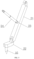
- FIG. 7 is a side cross-sectional view of a drill pipe of the present application.
- FIG. 8 is a diagram showing a positional relationship between the damping sliding shaft and a slider.
- a drilling device for geotechnical engineering investigation includes an outer supporting ring seat 1 , where a center of the outer supporting ring seat 1 is rotatably connected with a middle supporting ring seat 2 through a first supporting shaft rod 4 ; a center of the middle supporting ring seat 2 is rotatably connected with an inner supporting ring seat 3 through a second supporting shaft rod 5 ; the first supporting shaft rod 4 and the second supporting shaft rod 5 are vertically crossed; a second rotating motor 7 is fixedly installed at one end of the first supporting shaft rod 4 on an outer surface of the outer supporting ring seat 1 ; a pow output end of the second rotating motor 7 is fixedly connected with the first supporting shaft rod 4 , an other end of the first supporting shaft rod 4 is provided with a first locking mechanism for position limitation; a first rotating motor 6 is fixedly installed at one end of the second supporting shaft rod 5 on an outer surface of the middle supporting ring seat 2 , a power output end of the first rotating motor 6 is fixedly connected with
- a drill pipe limit seat 8 is fixedly installed right above the inner supporting ring seat 3 through a bracket, a drilling drive device 15 is arranged right above the drill pipe limit seat 8 , and a connecting support seat 16 is fixedly installed at a power output end of the drilling drive device 15 .
- a drill pipe 17 is fixedly installed at a bottom end of the connecting support seat 16 , a bottom end of the drill pipe 17 is rotatably connected inside the drill pipe limit seat 8 , a drainage mechanism for discharging liquid inside rocks is arranged inside the drill pipe 17 .
- a buffering mechanism for buffering and supporting the drilling drive device 15 is arranged between the connecting support seat 16 and the outer supporting ring seat 1 , and a bottom surface of the outer supporting ring seat 1 is provided with a bottom supporting mechanism fixedly connected with a ground.
- the buffering mechanism includes side supporting arms 9 fixedly welded to the outer surface of the outer supporting ring seat 1 and second universal ball shafts 18 rotatably connected to an outer surface of the connecting support seat 16 ; a top surface of each of the side supporting arms 9 is provided with a chute 12 ; a slider 10 is slidably connected inside the chute 12 .
- a top surface of the slider 10 is rotatably connected with a first universal ball shaft 11 ; a supporting hydraulic rod 19 is arranged between the first universal ball shaft 11 and corresponding one of the second universal ball shafts 18 and one end of the supporting hydraulic rod 19 is rotatably connected with the first universal ball shaft 11 and an other end of the supporting hydraulic rod 19 is rotatably connected with the corresponding one of the second universal ball shafts 18 . Therefore, the supporting hydraulic rod 19 at different positions are able to adaptively retract and rotate with the change of the angle of the drill pipe 17 and the stable supporting effect is further provided.
- the side supporting arms 9 are provided at least four.
- the side supporting arms are provided with four and are uniformly circumferentially arrayed on the outer surface of the outer supporting ring seat 1 .
- a number of the second universal ball shafts 18 is the same as that of the side supporting arms 9 , and positions of the second universal ball shafts 18 and the corresponding side supporting arms 9 are matched, which facilitates the drilling drive device 15 to be buffered and supported in all directions and further helps the staff to control the drilling drive device 15 and a situation where the excessive weight of the drilling drive device 15 leads to the failure in controlling the drilling drive device 15 by the staff is avoided.
- the bottom supporting mechanism includes mounting support seats 13 arranged on a bottom surface of each joint of the each of the side supporting arms 9 and the outer supporting ring seat 1 .
- a bottom end of each of the mounting support seats 13 is rotatably connected with a movable leg 21
- a bottom end of the movable leg 21 are rotatably connected with a grounding leg 22
- a bottom surface of the grounding leg 22 is provided with a fixing nail 35 , so that fixed connection with the ground in multi-height and multi-angle is realized.
- a top connecting seat 14 fixedly welded at one end of a bottom surface of the each of the side supporting arms 9 away from the inner supporting ring seat 3 , a bottom connecting seat 23 fixedly welded at a center of a top surface of the movable leg 21 , and a buffering hydraulic rod 24 arranged between the bottom connecting seat 23 and the top connecting seat 14 , where one end of the buffering hydraulic rod 24 is rotatably connected to the bottom connecting seat 23 , and an other end of the buffering hydraulic rod 24 is rotatably connected to the top connecting seat 14 , a stable triangular support structure is formed to provide stable support for the drilling device for geotechnical engineering investigation with higher support strength, and the buffering hydraulic rod 24 is utilized to buffer the drilling impact force.
- the first locking mechanism and the second locking mechanism both include supporting shells 25 fixedly installed on the outer surface of the outer supporting ring seat 1 and an outer surface of the middle supporting ring seat 2 ; brake gears 26 are arranged in the supporting shells 25 .
- Two brake gears 26 are fixedly sleeved ends of the first supporting shaft rod 4 and the second supporting shaft rod 5 respectively and a brake strut 27 is rotatably connected at one corner of a top end of the each of the supporting shells 25 .
- a brake chuck 28 is arranged adjacently to the top ends of each of the brake gears 26 .
- a brake cylinder 29 is fixedly installed at one end of the each of the supporting shells 25 adjacent to a rotating shaft of the brake strut 27 and a pow output end of the brake cylinder 29 is rotatably connected with a bottom end of the brake strut 27 .
- the brake cylinder 29 is used to push the brake strut 27 to rotate, so that the brake chuck 28 is inserted into or separated from the clamping groove on the surface of the brake gears 26 , thereby realizing the rotation locking of the first supporting shaft rod 4 and the second supporting shaft rod 5 .
- the drainage mechanism includes water inlet holes 30 arranged on a side of the bottom end of the drill pipe 17 and a drainage hollow groove 31 arranged inside the drill pipe 17 , and a water outlet 32 is arranged on a side of a top end of the drill pipe 17 , and the water outlet 32 is communicated with the drainage hollow groove 31 .
- the water outlet 32 is connected with a water pumping device 34 through a universal hose. Therefore, the liquid in water layer of rock and soil is discharged upward form the bottom of the drill pipe 17 through the water pumping device 34 .
- two sides of a bottom end of the drilling drive device 15 are symmetrically provided with handles 20 for conveniently controlling the drilling drive device 15 by the staff.
- the drilling device for geotechnical engineering investigation is stably connected with the ground through the grounding leg 22 to support the drilling device for geotechnical engineering investigation stably; then, the first supporting shaft rod 4 and the second supporting shaft rod 5 are respectively rotated by the first rotating motor 6 and the second rotating motor 7 according to the drilling needs, so as to drive the drill pipe 17 to rotate in the three-dimensional space until the drill pipe 17 rotates at a proper angle; at the same time, the supporting hydraulic rod 19 at different positions is adaptively retracted and rotated relative to the connecting support seat 16 , and the slider 10 at different positions is adaptively rotated inside the chute 12 .
- the drilling drive device 15 and the drill pipe 17 are further provided with adaptive support and buffer, and at the same time, the drilling drive device 15 and the drill pipe 17 are not prevented from rotating in three-dimensional space, so that the inclined drilling to the designated position is carried out.
- the rotating positions of the first supporting shaft rod 4 and the second supporting shaft rod 5 are locked through the first locking mechanism and the second locking mechanism after the drill pipe 17 is positionally adjusted, thereby avoiding position deviation caused by excessive impact force during drilling, and avoiding damage to the first rotating motor 6 and the second rotating motor 7 at the same time.
- the drilling drive device 15 drives the drill pipe 17 through the handles 20 to drill the rock and soil layer, and the drill pipe 17 continuously drills into the rock; at the same time, the buffering mechanism changes position adaptively to buffer and support the drill pipe 17 and the drill pipe 17 stops drilling in case of the rock and soil layer. Meanwhile, the water pumping device is communicated with the water outlet 32 and water inside the rock and soil layer is discharged out through the water inlet holes 30 and the drainage hollow groove 31 , thereby avoiding affecting the normal drilling.
Landscapes
- Engineering & Computer Science (AREA)
- Geology (AREA)
- Life Sciences & Earth Sciences (AREA)
- Mining & Mineral Resources (AREA)
- Physics & Mathematics (AREA)
- Environmental & Geological Engineering (AREA)
- Fluid Mechanics (AREA)
- General Life Sciences & Earth Sciences (AREA)
- Geochemistry & Mineralogy (AREA)
- Mechanical Engineering (AREA)
- General Engineering & Computer Science (AREA)
- Acoustics & Sound (AREA)
- Aviation & Aerospace Engineering (AREA)
- Earth Drilling (AREA)
- Sampling And Sample Adjustment (AREA)
Abstract
Description
Claims (10)
Applications Claiming Priority (4)
| Application Number | Priority Date | Filing Date | Title |
|---|---|---|---|
| CN202210093158.2A CN114482859A (en) | 2022-01-26 | 2022-01-26 | Drilling rig for geotechnical engineering investigation |
| CN2022100931582 | 2022-01-26 | ||
| CN202210093158.2 | 2022-01-26 | ||
| PCT/CN2022/125916 WO2023142542A1 (en) | 2022-01-26 | 2022-10-18 | Drilling apparatus for geotechnical engineering investigation |
Related Parent Applications (1)
| Application Number | Title | Priority Date | Filing Date |
|---|---|---|---|
| PCT/CN2022/125916 Continuation WO2023142542A1 (en) | 2022-01-26 | 2022-10-18 | Drilling apparatus for geotechnical engineering investigation |
Publications (2)
| Publication Number | Publication Date |
|---|---|
| US20230313615A1 US20230313615A1 (en) | 2023-10-05 |
| US12196080B2 true US12196080B2 (en) | 2025-01-14 |
Family
ID=81474375
Family Applications (1)
| Application Number | Title | Priority Date | Filing Date |
|---|---|---|---|
| US18/331,254 Active 2042-10-22 US12196080B2 (en) | 2022-01-26 | 2023-06-08 | Drilling device for geotechnical engineering investigation |
Country Status (4)
| Country | Link |
|---|---|
| US (1) | US12196080B2 (en) |
| CN (1) | CN114482859A (en) |
| LU (1) | LU504867B1 (en) |
| WO (1) | WO2023142542A1 (en) |
Families Citing this family (20)
| Publication number | Priority date | Publication date | Assignee | Title |
|---|---|---|---|---|
| CN114482859A (en) | 2022-01-26 | 2022-05-13 | 桂林理工大学 | Drilling rig for geotechnical engineering investigation |
| CN116752902B (en) * | 2023-08-10 | 2023-10-20 | 山东省地矿工程集团有限公司 | Horizontal directional drilling equipment for improving drilling precision |
| CN117553761B (en) * | 2023-11-14 | 2024-05-14 | 蒙阴县自然资源和规划局 | Intelligent land measuring instrument convenient to adjust |
| CN117684873B (en) * | 2024-02-04 | 2024-05-03 | 山东省地质矿产勘查开发局第七地质大队(山东省第七地质矿产勘查院) | Fully-mechanized mining face drilling machine drilling stabilizing mechanism |
| CN118029915B (en) * | 2024-04-12 | 2024-06-25 | 兰州城市学院 | Drilling deviation prevention device for geological survey |
| CN118050205B (en) * | 2024-04-16 | 2024-06-11 | 山东省国土空间生态修复中心(山东省地质灾害防治技术指导中心、山东省土地储备中心) | Core extractor for geological remains on site |
| CN118088157B (en) * | 2024-04-17 | 2024-06-28 | 山东省地矿工程勘察院(山东省地质矿产勘查开发局八〇一水文地质工程地质大队) | Automatic measuring device for water level of engineering geological survey drilling hole |
| CN118442003B (en) * | 2024-04-30 | 2024-11-12 | 中建材岩土工程江苏有限公司 | An efficient exploration equipment for engineering survey |
| CN118241992B (en) * | 2024-05-29 | 2024-09-17 | 徐州景云祥机械制造有限公司 | Intelligent regulation rig of many geological environment of self-adaptation |
| CN118407393B (en) * | 2024-07-03 | 2025-04-11 | 江西九勘地质工程技术有限公司 | A drilling device for construction engineering survey |
| CN118835921B (en) * | 2024-07-09 | 2025-01-21 | 国家能源集团西藏电力有限公司忠玉分公司 | A grouting and drilling device for ice-water accumulation block gravel soil covering layer |
| CN118481541B (en) * | 2024-07-10 | 2024-10-29 | 中铁七局集团西安铁路工程有限公司 | Drilling machine for construction of railway tunnel drain hole |
| CN118687911B (en) * | 2024-08-26 | 2024-11-15 | 湘潭大学 | Underwater rock-soil foundation exploration sampling equipment suitable for geotechnical engineering |
| CN118911596B (en) * | 2024-10-10 | 2025-01-24 | 山东省煤炭技术服务有限公司 | A survey equipment for geological engineering survey research |
| CN118911613B (en) * | 2024-10-11 | 2024-11-29 | 内蒙古工业大学 | An efficient drilling rig for engineering geological survey |
| CN119163353B (en) * | 2024-11-21 | 2025-02-14 | 山东省煤田地质局第一勘探队 | Mountain rock seam detection method and detection device for geological survey |
| CN119266743B (en) * | 2024-12-12 | 2025-02-25 | 成都锦城学院 | Drilling guiding device for foundation pile foundation holes |
| CN119374959A (en) * | 2024-12-31 | 2025-01-28 | 山东同建工程勘测有限公司 | Sampling device for land engineering survey |
| CN119618726B (en) * | 2025-02-12 | 2025-04-29 | 西南交通建设集团股份有限公司 | Ground sampling device is used in building engineering reconnaissance |
| CN120119891B (en) * | 2025-05-13 | 2025-07-29 | 河南中矿能源有限公司 | Mineral geological investigation device convenient to installation |
Citations (13)
| Publication number | Priority date | Publication date | Assignee | Title |
|---|---|---|---|---|
| RU2401376C1 (en) | 2009-04-06 | 2010-10-10 | Юрий Николаевич Щербаков | Mobile drilling jig (versions) |
| US20140238747A1 (en) * | 2013-02-25 | 2014-08-28 | Paul J. Fabian | Auger stand for a utility truck and method of using same |
| CN207212268U (en) | 2017-10-12 | 2018-04-10 | 平顶山工业职业技术学院 | A kind of stratigraphic analysis drilling rig |
| CN210829096U (en) * | 2019-08-02 | 2020-06-23 | 朱斌 | Drilling rig for geotechnical engineering investigation |
| CN212337176U (en) | 2020-06-02 | 2021-01-12 | 东北岩土工程勘察有限公司 | Drilling rig for geotechnical engineering investigation |
| CN112324355A (en) | 2020-11-18 | 2021-02-05 | 江苏省岩土工程勘察设计研究院 | Drilling device and drilling process for geotechnical engineering investigation |
| US20210123202A1 (en) * | 2017-10-19 | 2021-04-29 | Soletanche Freyssinet | System for anchoring a pile or jacket and corresponding method |
| CN113250615A (en) * | 2021-07-16 | 2021-08-13 | 山东辛丁技术有限公司 | Vertical rock drilling device and drilling method |
| CN113863869A (en) * | 2021-09-30 | 2021-12-31 | 中化明达(福建)地质勘测有限公司 | Drilling device and drilling process for geotechnical engineering investigation |
| CN114482859A (en) | 2022-01-26 | 2022-05-13 | 桂林理工大学 | Drilling rig for geotechnical engineering investigation |
| CN117432334A (en) * | 2023-11-07 | 2024-01-23 | 青岛中油岩土工程有限公司 | Multi-terrain geotechnical engineering investigation directional drilling equipment |
| CN117927139A (en) * | 2024-01-17 | 2024-04-26 | 四川中水成勘院工程物探检测有限公司 | A directional drilling system for multi-terrain geotechnical engineering survey |
| CN118029915A (en) * | 2024-04-12 | 2024-05-14 | 兰州城市学院 | Drilling deviation prevention device for geological survey |
-
2022
- 2022-01-26 CN CN202210093158.2A patent/CN114482859A/en active Pending
- 2022-10-18 WO PCT/CN2022/125916 patent/WO2023142542A1/en not_active Ceased
- 2022-10-18 LU LU504867A patent/LU504867B1/en active IP Right Grant
-
2023
- 2023-06-08 US US18/331,254 patent/US12196080B2/en active Active
Patent Citations (15)
| Publication number | Priority date | Publication date | Assignee | Title |
|---|---|---|---|---|
| RU2401376C1 (en) | 2009-04-06 | 2010-10-10 | Юрий Николаевич Щербаков | Mobile drilling jig (versions) |
| US20140238747A1 (en) * | 2013-02-25 | 2014-08-28 | Paul J. Fabian | Auger stand for a utility truck and method of using same |
| CN207212268U (en) | 2017-10-12 | 2018-04-10 | 平顶山工业职业技术学院 | A kind of stratigraphic analysis drilling rig |
| US11220800B2 (en) * | 2017-10-19 | 2022-01-11 | Soletanche Freyssinet | System for anchoring a pile or jacket and corresponding method |
| US20210123202A1 (en) * | 2017-10-19 | 2021-04-29 | Soletanche Freyssinet | System for anchoring a pile or jacket and corresponding method |
| CN210829096U (en) * | 2019-08-02 | 2020-06-23 | 朱斌 | Drilling rig for geotechnical engineering investigation |
| CN212337176U (en) | 2020-06-02 | 2021-01-12 | 东北岩土工程勘察有限公司 | Drilling rig for geotechnical engineering investigation |
| CN112324355A (en) | 2020-11-18 | 2021-02-05 | 江苏省岩土工程勘察设计研究院 | Drilling device and drilling process for geotechnical engineering investigation |
| CN113250615A (en) * | 2021-07-16 | 2021-08-13 | 山东辛丁技术有限公司 | Vertical rock drilling device and drilling method |
| CN113863869A (en) * | 2021-09-30 | 2021-12-31 | 中化明达(福建)地质勘测有限公司 | Drilling device and drilling process for geotechnical engineering investigation |
| CN114482859A (en) | 2022-01-26 | 2022-05-13 | 桂林理工大学 | Drilling rig for geotechnical engineering investigation |
| US20230313615A1 (en) * | 2022-01-26 | 2023-10-05 | Guilin University Of Technology | Drilling device for geotechnical engineering investigation |
| CN117432334A (en) * | 2023-11-07 | 2024-01-23 | 青岛中油岩土工程有限公司 | Multi-terrain geotechnical engineering investigation directional drilling equipment |
| CN117927139A (en) * | 2024-01-17 | 2024-04-26 | 四川中水成勘院工程物探检测有限公司 | A directional drilling system for multi-terrain geotechnical engineering survey |
| CN118029915A (en) * | 2024-04-12 | 2024-05-14 | 兰州城市学院 | Drilling deviation prevention device for geological survey |
Also Published As
| Publication number | Publication date |
|---|---|
| WO2023142542A1 (en) | 2023-08-03 |
| LU504867B1 (en) | 2023-12-04 |
| CN114482859A (en) | 2022-05-13 |
| US20230313615A1 (en) | 2023-10-05 |
Similar Documents
| Publication | Publication Date | Title |
|---|---|---|
| US12196080B2 (en) | Drilling device for geotechnical engineering investigation | |
| CN104879059B (en) | A kind of multifunctional drill full circle swinging angle adjusting mechanism | |
| CN103046866B (en) | Universal rotating drilling machine | |
| CN102996063A (en) | Drilling mechanism for mine rock drilling and tunneling | |
| CN110259373B (en) | Low headroom rotary drill | |
| CN206513311U (en) | Jumbolter | |
| CN106013150B (en) | A kind of pile press machine | |
| CN102678062A (en) | Support mechanism and rotary drill rig | |
| CN104775754A (en) | Pole disc type multi-boom drill jumbo | |
| CN207686728U (en) | Constructing tunnel equipment | |
| CN104695869A (en) | Right-angle compound-coordinate drilling arm | |
| CN110924861A (en) | Walking Omni-directional Rotary Hydraulic Pile Foundation Drilling Machine | |
| CN102536117B (en) | Machine-mounted type multipurpose anchor rod drilling machine | |
| CN204492677U (en) | A kind of right-angle type composite coordinate drill boom | |
| CN221032617U (en) | Pitching and slewing coupling mechanism of drilling machine | |
| CN211202024U (en) | Wing type arm frame and anchor rod drill arm with same | |
| CN207332774U (en) | A kind of arm support bearing and drill jumbo | |
| CN202970431U (en) | Drilling mechanism for mine rock drilling tunneling | |
| CN205934925U (en) | Pile pressing machine | |
| CN106761416A (en) | A kind of reaming rig | |
| CN216811675U (en) | Tunneling and anchoring all-in-one machine with multifunctional drilling machine system | |
| CN217897907U (en) | Tunnel arch frame anchor rod construction device and tunnel construction equipment comprising same | |
| CN202031488U (en) | Supporting device and engineering machine | |
| KR102515073B1 (en) | Rock splitting device detachable on rock drill | |
| CN204716129U (en) | Multifunctional drill full circle swinging angle adjusting mechanism |
Legal Events
| Date | Code | Title | Description |
|---|---|---|---|
| AS | Assignment |
Owner name: GUILIN UNIVERSITY OF TECHNOLOGY, CHINA Free format text: ASSIGNMENT OF ASSIGNORS INTEREST;ASSIGNORS:SONG, YU;ZHANG, MINGZHI;LI, JUN;AND OTHERS;REEL/FRAME:063891/0236 Effective date: 20230607 |
|
| FEPP | Fee payment procedure |
Free format text: ENTITY STATUS SET TO UNDISCOUNTED (ORIGINAL EVENT CODE: BIG.); ENTITY STATUS OF PATENT OWNER: SMALL ENTITY |
|
| FEPP | Fee payment procedure |
Free format text: ENTITY STATUS SET TO SMALL (ORIGINAL EVENT CODE: SMAL); ENTITY STATUS OF PATENT OWNER: SMALL ENTITY |
|
| STPP | Information on status: patent application and granting procedure in general |
Free format text: DOCKETED NEW CASE - READY FOR EXAMINATION |
|
| STPP | Information on status: patent application and granting procedure in general |
Free format text: NON FINAL ACTION MAILED |
|
| STPP | Information on status: patent application and granting procedure in general |
Free format text: RESPONSE TO NON-FINAL OFFICE ACTION ENTERED AND FORWARDED TO EXAMINER |
|
| STPP | Information on status: patent application and granting procedure in general |
Free format text: NOTICE OF ALLOWANCE MAILED -- APPLICATION RECEIVED IN OFFICE OF PUBLICATIONS |
|
| STPP | Information on status: patent application and granting procedure in general |
Free format text: PUBLICATIONS -- ISSUE FEE PAYMENT RECEIVED |
|
| STPP | Information on status: patent application and granting procedure in general |
Free format text: PUBLICATIONS -- ISSUE FEE PAYMENT VERIFIED |
|
| STCF | Information on status: patent grant |
Free format text: PATENTED CASE |