US12181663B2 - Imaging device, adjustment method, and adjustment program - Google Patents
Imaging device, adjustment method, and adjustment program Download PDFInfo
- Publication number
- US12181663B2 US12181663B2 US18/153,359 US202318153359A US12181663B2 US 12181663 B2 US12181663 B2 US 12181663B2 US 202318153359 A US202318153359 A US 202318153359A US 12181663 B2 US12181663 B2 US 12181663B2
- Authority
- US
- United States
- Prior art keywords
- imaging device
- adjustment
- image
- field lens
- multispectral camera
- Prior art date
- Legal status (The legal status is an assumption and is not a legal conclusion. Google has not performed a legal analysis and makes no representation as to the accuracy of the status listed.)
- Active, expires
Links
Images











Classifications
-
- G—PHYSICS
- G02—OPTICS
- G02B—OPTICAL ELEMENTS, SYSTEMS OR APPARATUS
- G02B27/00—Optical systems or apparatus not provided for by any of the groups G02B1/00 - G02B26/00, G02B30/00
- G02B27/0081—Optical systems or apparatus not provided for by any of the groups G02B1/00 - G02B26/00, G02B30/00 with means for altering, e.g. enlarging, the entrance or exit pupil
-
- G—PHYSICS
- G01—MEASURING; TESTING
- G01J—MEASUREMENT OF INTENSITY, VELOCITY, SPECTRAL CONTENT, POLARISATION, PHASE OR PULSE CHARACTERISTICS OF INFRARED, VISIBLE OR ULTRAVIOLET LIGHT; COLORIMETRY; RADIATION PYROMETRY
- G01J3/00—Spectrometry; Spectrophotometry; Monochromators; Measuring colours
- G01J3/28—Investigating the spectrum
- G01J3/30—Measuring the intensity of spectral lines directly on the spectrum itself
- G01J3/36—Investigating two or more bands of a spectrum by separate detectors
-
- G—PHYSICS
- G02—OPTICS
- G02B—OPTICAL ELEMENTS, SYSTEMS OR APPARATUS
- G02B13/00—Optical objectives specially designed for the purposes specified below
-
- G—PHYSICS
- G02—OPTICS
- G02B—OPTICAL ELEMENTS, SYSTEMS OR APPARATUS
- G02B13/00—Optical objectives specially designed for the purposes specified below
- G02B13/0095—Relay lenses or rod lenses
-
- G—PHYSICS
- G02—OPTICS
- G02B—OPTICAL ELEMENTS, SYSTEMS OR APPARATUS
- G02B15/00—Optical objectives with means for varying the magnification
-
- G—PHYSICS
- G02—OPTICS
- G02B—OPTICAL ELEMENTS, SYSTEMS OR APPARATUS
- G02B21/00—Microscopes
- G02B21/36—Microscopes arranged for photographic purposes or projection purposes or digital imaging or video purposes including associated control and data processing arrangements
-
- G—PHYSICS
- G02—OPTICS
- G02B—OPTICAL ELEMENTS, SYSTEMS OR APPARATUS
- G02B3/00—Simple or compound lenses
-
- G—PHYSICS
- G02—OPTICS
- G02B—OPTICAL ELEMENTS, SYSTEMS OR APPARATUS
- G02B5/00—Optical elements other than lenses
- G02B5/005—Diaphragms
-
- G—PHYSICS
- G02—OPTICS
- G02B—OPTICAL ELEMENTS, SYSTEMS OR APPARATUS
- G02B5/00—Optical elements other than lenses
- G02B5/20—Filters
-
- G—PHYSICS
- G02—OPTICS
- G02B—OPTICAL ELEMENTS, SYSTEMS OR APPARATUS
- G02B5/00—Optical elements other than lenses
- G02B5/30—Polarising elements
-
- G—PHYSICS
- G02—OPTICS
- G02B—OPTICAL ELEMENTS, SYSTEMS OR APPARATUS
- G02B7/00—Mountings, adjusting means, or light-tight connections, for optical elements
-
- G—PHYSICS
- G02—OPTICS
- G02B—OPTICAL ELEMENTS, SYSTEMS OR APPARATUS
- G02B7/00—Mountings, adjusting means, or light-tight connections, for optical elements
- G02B7/006—Filter holders
-
- G—PHYSICS
- G02—OPTICS
- G02B—OPTICAL ELEMENTS, SYSTEMS OR APPARATUS
- G02B7/00—Mountings, adjusting means, or light-tight connections, for optical elements
- G02B7/02—Mountings, adjusting means, or light-tight connections, for optical elements for lenses
-
- G—PHYSICS
- G03—PHOTOGRAPHY; CINEMATOGRAPHY; ANALOGOUS TECHNIQUES USING WAVES OTHER THAN OPTICAL WAVES; ELECTROGRAPHY; HOLOGRAPHY
- G03B—APPARATUS OR ARRANGEMENTS FOR TAKING PHOTOGRAPHS OR FOR PROJECTING OR VIEWING THEM; APPARATUS OR ARRANGEMENTS EMPLOYING ANALOGOUS TECHNIQUES USING WAVES OTHER THAN OPTICAL WAVES; ACCESSORIES THEREFOR
- G03B11/00—Filters or other obturators specially adapted for photographic purposes
-
- H—ELECTRICITY
- H04—ELECTRIC COMMUNICATION TECHNIQUE
- H04N—PICTORIAL COMMUNICATION, e.g. TELEVISION
- H04N23/00—Cameras or camera modules comprising electronic image sensors; Control thereof
- H04N23/10—Cameras or camera modules comprising electronic image sensors; Control thereof for generating image signals from different wavelengths
-
- H—ELECTRICITY
- H04—ELECTRIC COMMUNICATION TECHNIQUE
- H04N—PICTORIAL COMMUNICATION, e.g. TELEVISION
- H04N23/00—Cameras or camera modules comprising electronic image sensors; Control thereof
- H04N23/10—Cameras or camera modules comprising electronic image sensors; Control thereof for generating image signals from different wavelengths
- H04N23/11—Cameras or camera modules comprising electronic image sensors; Control thereof for generating image signals from different wavelengths for generating image signals from visible and infrared light wavelengths
-
- H—ELECTRICITY
- H04—ELECTRIC COMMUNICATION TECHNIQUE
- H04N—PICTORIAL COMMUNICATION, e.g. TELEVISION
- H04N23/00—Cameras or camera modules comprising electronic image sensors; Control thereof
- H04N23/45—Cameras or camera modules comprising electronic image sensors; Control thereof for generating image signals from two or more image sensors being of different type or operating in different modes, e.g. with a CMOS sensor for moving images in combination with a charge-coupled device [CCD] for still images
-
- H—ELECTRICITY
- H04—ELECTRIC COMMUNICATION TECHNIQUE
- H04N—PICTORIAL COMMUNICATION, e.g. TELEVISION
- H04N23/00—Cameras or camera modules comprising electronic image sensors; Control thereof
- H04N23/50—Constructional details
- H04N23/55—Optical parts specially adapted for electronic image sensors; Mounting thereof
-
- H—ELECTRICITY
- H04—ELECTRIC COMMUNICATION TECHNIQUE
- H04N—PICTORIAL COMMUNICATION, e.g. TELEVISION
- H04N23/00—Cameras or camera modules comprising electronic image sensors; Control thereof
- H04N23/60—Control of cameras or camera modules
-
- H—ELECTRICITY
- H04—ELECTRIC COMMUNICATION TECHNIQUE
- H04N—PICTORIAL COMMUNICATION, e.g. TELEVISION
- H04N23/00—Cameras or camera modules comprising electronic image sensors; Control thereof
- H04N23/60—Control of cameras or camera modules
- H04N23/63—Control of cameras or camera modules by using electronic viewfinders
- H04N23/633—Control of cameras or camera modules by using electronic viewfinders for displaying additional information relating to control or operation of the camera
-
- H—ELECTRICITY
- H04—ELECTRIC COMMUNICATION TECHNIQUE
- H04N—PICTORIAL COMMUNICATION, e.g. TELEVISION
- H04N23/00—Cameras or camera modules comprising electronic image sensors; Control thereof
- H04N23/70—Circuitry for compensating brightness variation in the scene
- H04N23/71—Circuitry for evaluating the brightness variation
Definitions
- the present invention relates to an imaging device that captures multispectral images, and an adjustment method and an adjustment program for the imaging device.
- JP2019-082412A discloses an imaging device that comprises a spectral filter array and a field lens.
- One embodiment of a technique of the present disclosure provides an imaging device, an adjustment method, and an adjustment program that can acquire multispectral images having good image quality.
- An imaging device is disposed on an image side of another optical system, and comprises a multispectral camera that acquires images in a plurality of wavelength ranges, a field lens that relays the other optical system to the multispectral camera, and an adjustment mechanism that adjusts a conjugate relationship between an emission pupil position of the other optical system and an incident pupil position of the multispectral camera.
- the multispectral camera includes: a wavelength polarizing filter unit including a frame which is disposed at a pupil position or near the pupil position and includes a plurality of aperture regions and in which centroids of the plurality of aperture regions are different from each other, a plurality of optical filters that are arranged in the plurality of aperture regions and include two or more optical filters transmitting lights having at least a part of wavelength ranges different from each other, and a plurality of polarizing filters that are arranged in the plurality of aperture regions and have different polarization directions; an imaging element that includes a plurality of pixel groups receiving light transmitted through any of the plurality of aperture regions; and a processor that generates an image on the basis of a plurality of image signals output from the imaging element.
- a wavelength polarizing filter unit including a frame which is disposed at a pupil position or near the pupil position and includes a plurality of aperture regions and in which centroids of the plurality of aperture regions are different from each other, a plurality of optical filters that are arranged in the plurality
- the adjustment mechanism adjusts a distance between the other optical system and the field lens.
- the adjustment mechanism adjusts a distance between the field lens and the multispectral camera.
- the adjustment mechanism adjusts a distance between the emission pupil position of the other optical system and the field lens and a distance between the field lens and the incident pupil position of the multispectral camera.
- the adjustment mechanism keeps an image magnification constant to make the adjustment.
- the adjustment mechanism changes a position of the wavelength polarizing filter unit and/or a focal length of the field lens to keep the image magnification constant.
- the adjustment mechanism is an attachment and detachment mechanism for the wavelength polarizing filter unit.
- the processor outputs image support information required for the adjustment.
- the imaging device further comprises a display device and the processor outputs the image support information based on light and darkness information of at least one spectral image obtained from the multispectral camera.
- the processor outputs a procedure of the adjustment serving as the image support information on the basis of a direction of the aperture region and the light and darkness information.
- the imaging device according to any one of the eighth to tenth aspects further comprises a display device and the display device displays at least one of the image support information output from the processor or a procedure of the adjustment serving as the image support information.
- An adjustment method is an adjustment method for an imaging device that is disposed on an image side of another optical system.
- the imaging device includes: a multispectral camera that includes a frame, a plurality of optical filters, and a plurality of polarizing filters and acquires images in a plurality of wavelength ranges, the frame disposed at a pupil position or near the pupil position and including a plurality of aperture regions, centroids of the plurality of aperture regions being different from each other, the plurality of optical filters being arranged in the plurality of aperture regions and including two or more optical filters transmitting lights having at least a part of wavelength ranges different from each other, and a plurality of polarizing filters being arranged in the plurality of aperture regions and having different polarization directions; a field lens that relays the other optical system to the multispectral camera; and an adjustment mechanism that adjusts a conjugate relationship between an emission pupil position of the other optical system and an incident pupil position of the multispectral camera.
- the adjustment method comprises an output step of
- the image support information based on light and darkness information of at least one spectral image obtained from the multispectral camera is displayed on a display device.
- a procedure of the adjustment serving as the image support information is displayed on the display device on the basis of a direction of the aperture region and the light and darkness information.
- An adjustment program causes a computer to perform the adjustment method according to any one of the twelfth to fourteenth aspects.
- FIG. 1 is a diagram showing a configuration of an imaging system according to a first embodiment.
- FIG. 2 is a diagram showing a configuration of an imaging device.
- FIGS. 3 A, 3 B, 3 C, and 3 D are conceptual diagrams showing aspects of the adjustment of a conjugate relationship depending on the exchange or the like of each element.
- FIGS. 4 A, 4 B, and 4 C are diagrams showing an example of an adjustment mechanism for a field lens.
- FIGS. 5 A and 5 B are diagrams showing another example of the adjustment mechanism for the field lens.
- FIG. 6 is a perspective view of a multispectral camera.
- FIG. 7 is a cross-sectional view of the multispectral camera.
- FIGS. 8 A, 8 B, 8 C, 8 D, 8 E, and 8 F are diagrams showing the configuration of a frame.
- FIG. 9 is a diagram showing a configuration of a wavelength polarizing filter unit.
- FIGS. 10 A, 10 B, 10 C, and 10 D are diagrams showing polarization directions of polarizing filters.
- FIG. 11 is a diagram showing a configuration of an imaging element.
- FIG. 12 is a diagram showing a configuration of a processor.
- FIG. 13 is a table showing an example of a relationship between the relative position and the like of the field lens and elements to be adjusted.
- FIGS. 14 A, 14 B, 14 C, and 14 D are diagrams showing aspects of adjustment in Cases 1 to 4.
- FIG. 15 is another diagram showing an aspect of adjustment in Case 5.
- FIG. 16 is a flowchart (1/2) showing a procedure for the adjustment of a conjugate relationship.
- FIG. 17 is a flowchart (2/2) showing a procedure for the adjustment of a conjugate relationship.
- FIGS. 18 A, 18 B, and 18 C are conceptual diagrams showing a relationship between a direction of an aperture region and the light and darkness information of a spectral image.
- FIG. 19 is a table showing an influence of the shapes of aperture regions on the adjustment of a conjugate relationship.
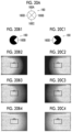
- FIGS. 20 A , 20 B 1 , 20 B 2 , 20 B 3 , 20 B 4 , 20 C 1 , 20 C 2 , 20 C 3 , and 20 C 4 are diagrams showing specific examples of the adjustment of a conjugate relationship in which the shapes of aperture regions are considered.
- FIG. 21 is a diagram showing an aspect of connection to a microscope.
- FIG. 22 is a diagram showing an aspect of connection to a zooming optical system.
- FIG. 23 is a diagram showing a system configuration in a case where elements are not connected to each other.
- a multispectral camera capable of capturing images in a plurality of wavelength ranges is used in combination with another optical system, images can be captured in the plurality of wavelength ranges even in an optical system not having a multispectral imaging function.
- the multispectral camera is relayed to another optical system and a conjugate relationship of pupils is not appropriately adjusted, there is a concern that the amount of light will be reduced in a peripheral region or the like in an imaging angle of view (there is a concern that so-called “vignetting” will occur).
- a field lens is inserted into a general relay optical system to improve a conjugate relationship of pupils.
- FIG. 1 is a diagram showing a configuration of an imaging system 10 (an imaging system, an imaging device) according to a first embodiment.
- the imaging system 10 includes an optical system 20 (another optical system; including a lens 22 ), an imaging device 100 , a display device 300 (a display device, such as a liquid crystal display), a storage device 310 (a magneto-optical recording device, a semiconductor memory, or the like), and an operation unit 320 (a keyboard, a mouse, switches, or the like); and the imaging device 100 is disposed on an image side of the optical system 20 .
- a speaker that outputs image support information to be described later as a voice may be provided.
- An example of the optical system 20 will be described later (see FIGS. 21 and 22 ).
- FIG. 2 is a diagram showing a configuration of the imaging device 100 (imaging device).
- the imaging device 100 comprises a mount adapter 110 (adjustment mechanism), a field lens unit 120 (field lens), a multispectral camera 130 (multispectral camera), and an imaging device body 140 (multispectral camera).
- a field lens 122 is a lens that relays the optical system 20 to the multispectral camera 130 .
- a screw mount can be attached to and detached from each other by a screw mount or a bayonet mount (each of these mounts is an aspect of the adjustment mechanism).
- Standards for a screw mount include, for example, a C mount and a CS mount.
- the C mount has a diameter of 25.4 mm, a screw pitch of 0.794 mm, and a flange back of 17.526 mm (see FIG. 2 ).
- the adjustment of a conjugate relationship is to conjugate an emission pupil position of the optical system 20 (another optical system) to an incident pupil position of the imaging device 100 (imaging device), and a user adjusts a conjugate relationship using the attachment and detachment of elements having different sizes and different characteristics, the movement of the lens, or the like (an adjustment made by the adjustment mechanism). Accordingly, it is possible to prevent a reduction in the amount of light at a peripheral portion of a spectral image (vignetting).
- the adjustment of a conjugate relationship can be made on the basis of the light and darkness information of spectral images.
- a processor 142 calculates light and darkness information of at least one spectral image obtained from the multispectral camera 130 (light amount distribution in an image), and generates and outputs information (image support information) required for the adjustment of a conjugate relationship on the basis of the light and darkness information.
- image support information information required for the adjustment of a conjugate relationship on the basis of the light and darkness information.
- a user can adjust a conjugate relationship by performing the attachment and detachment, exchange, movement, or the like of components according to this image support information.
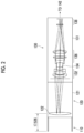
- FIGS. 3 A, 3 B, 3 C, and 3 D are conceptual diagrams showing aspects of the adjustment of a conjugate relationship depending on the exchange or the like of each element.
- the imaging device 100 can include a mount adapter 110 A (adjustment mechanism), a field lens unit 120 A including a field lens 122 A, and a multispectral camera 130 A (a lens and an imaging device body are not shown).
- a mount adapter 110 B (adjustment mechanism) different from the mount adapter 110 A in terms of a size (a length in a direction of an optical axis) is mounted as shown in FIG. 3 B in this case, a distance between the optical system 20 and the imaging device 100 can be adjusted to adjust a conjugate relationship.
- a distance between the optical system 20 and the field lens can also be adjusted to adjust a conjugate relationship.
- the lens may be moved forward or backward in a state where a unit having a specific configuration is mounted to change a focal length and/or an image magnification.
- FIG. 3 D shows an aspect of an adjustment made by a multispectral camera, and a conjugate relationship can be adjusted in a case where a multispectral camera 130 B including a lens different from a lens of the multispectral camera 130 A in terms of a focal length and/or an image magnification is mounted. Further, even in a case where an adjustment is to be made by the multispectral camera, a lens may be moved forward or backward in a state where a camera having a specific configuration is mounted to change a focal length and/or an image magnification.
- the mount adapter Only any one of adjustments to be made by the mount adapter, the field lens unit, and the multispectral camera may be performed, or a plurality of the adjustments may be performed in combination.
- a distance between the emission pupil position of the optical system 20 (another optical system) and a field lens and a distance between the field lens and an incident pupil position of the multispectral camera can be adjusted.
- the field lens unit 120 includes a lens barrel 121 and the field lens 122 (field lens).
- the field lens 122 is moved forward or backward in a direction of an optical axis L in a case where a user operates the adjustment mechanism to be described later.
- the field lens 122 may be composed of one lens or may be composed of a plurality of lenses.
- FIGS. 4 A, 4 B, and 4 C are diagrams showing an example of an adjustment mechanism for the field lens.
- FIG. 4 A is a perspective view of a lens barrel 124 A, and three slits 126 A are formed in the lens barrel 124 A in a direction parallel to the optical axis L.
- FIG. 4 B is a front view of a lens unit 128 , and the field lens 122 and three arms 127 are shown in FIG. 4 B .
- FIG. 4 C shows a state where the arms 127 are inserted into the slits 126 A so that the lens unit 128 is mounted on the lens barrel 124 A. The arms 127 can be moved in the slits 126 A in the direction of the optical axis L in the state shown in FIG.
- the field lens 122 is composed of a plurality of lenses
- such adjustment mechanisms may be provided for some of the plurality of lenses or the adjustment mechanisms may be provided for all the plurality of lenses.
- FIGS. 5 A and 5 B are diagrams showing another example of the adjustment mechanism for the field lens.
- FIG. 5 A is a perspective view of a lens barrel 124 B, and a helical slit 126 B about the optical axis L is formed in the lens barrel 124 B.
- FIG. 5 B shows a state where the same lens unit 128 as the lens unit shown in FIGS. 4 B and 4 C is mounted on the lens barrel 124 B (a state where the arms 127 are inserted into the slit 126 B).
- the lens unit 128 can be moved forward or backward while being rotated about the optical axis L in the state shown in FIG. 5 B , so that a user can move the field lens 122 forward or backward.
- a distance between the field lens 122 and the optical system 20 (another optical system) and/or the multispectral camera 130 can be changed by the adjustment mechanism shown in FIGS. 4 A, 4 B, and 4 C or FIGS. 5 A and 5 B . Further, the field lens 122 may be moved forward or backward to change a focal length so that an image magnification is kept constant.
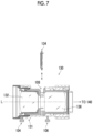
- FIGS. 6 and 7 are a perspective view and a cross-sectional view of the multispectral camera 130 , respectively.
- an optical system including a first lens 132 and a second lens 136 is disposed in a lens barrel 131 of the multispectral camera 130 and these lenses are moved forward or backward in the direction of the optical axis L in a case where a first lever 104 and a second lever 106 are rotationally moved, so that a focal length and/or an image magnification is adjusted.
- Each of the first lens 132 and the second lens 136 may be a lens group composed of a plurality of lenses.
- the same mechanism (the lens barrel, the arms, the slits, and the like) as that in the case of the field lens unit can be used for the forward or backward movement of the first lens 132 and the second lens 136 (see FIGS. 4 A, 4 B, and 4 C and FIGS. 5 A and 5 B ). That is, these mechanisms form the adjustment mechanism.
- a slit 108 (an attachment and detachment mechanism for a wavelength polarizing filter unit) is formed in the lens barrel 131 at a pupil position of the imaging device 100 or near the pupil position, and a wavelength polarizing filter unit 134 (wavelength polarizing filter unit) is inserted into the slit 108 and is disposed in a state where an optical axis of the wavelength polarizing filter unit 134 coincides with the optical axis L of the imaging optical system (the first lens 132 and the second lens 136 ).
- FIGS. 8 A, 8 B, 8 C, 8 D, 8 E, and 8 F are diagrams showing a configuration of a frame 135
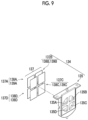
- FIG. 9 is a diagram showing a configuration of the wavelength polarizing filter unit 134
- FIGS. 8 A to 8 F are a rear view, a top view, a left side view, a bottom view, a perspective view, and a front view of the frame 135 and/or the wavelength polarizing filter unit 134 , respectively.
- the frame 135 comprises four aperture regions 135 A to 135 D (a plurality of aperture regions).
- the centroids of these aperture regions 135 A to 135 D are different from each other and are also different from a centroid 135 G of all the aperture regions.
- the shape of each of the aperture regions 135 A to 135 D is not limited to a fan shape shown in FIGS. 8 E, 8 F, and 9 , and may be another shape, such as a circular shape, a rectangular shape, or a polygonal shape. Further, the shapes and sizes of the aperture regions may be different from each other.
- filter sets 137 A to 137 D (a plurality of optical filters and a plurality of polarizing filters) are disposed in these aperture regions (on the back side of the frame 135 ), respectively.
- the filter sets 137 A to 137 D may be fixed using an adhesive.
- the filter set 137 A has a configuration in which an optical filter 138 A and a polarizing filter 139 A are superimposed as shown in FIG. 9 .
- the filter set 137 B has a configuration in which an optical filter 138 B and a polarizing filter 139 B are superimposed.
- the filter set 137 C has a configuration in which an optical filter 138 C and a polarizing filter 139 C are superimposed.
- the filter set 137 D comprises an optical filter 138 D and a polarizing filter 139 D.
- the optical filters 138 A to 138 D are a plurality of optical filters (color filters) including two or more optical filters that transmit lights having at least a part of wavelength ranges different from each other, and the polarizing filters 139 A to 139 D are a plurality of polarizing filters having different polarization directions.
- FIGS. 10 A, 10 B, 10 C, and 10 D are diagrams showing examples of the polarization directions of the polarizing filters, and the polarization directions of the polarizing filters 139 A to 139 D can be set to four directions (of which the number is equal to the number of the aperture regions; for example, 0°, 45°, 90°, and 135°) at most as illustrated in FIGS. 10 A to 10 D .
- Each of the polarizing filters 139 A to 139 D may be a filter that polarizes light using a polarizing film or may be a filter that polarizes light using wire grids or a plurality of slits.
- the wavelength polarizing filter unit 134 having the above-mentioned configuration can be inserted into and removed from the slit 108 , so that an attachment and detachment mechanism for the wavelength polarizing filter unit 134 is formed.
- a user can select and use a wavelength polarizing filter unit having a desired wavelength range or a wavelength polarizing filter unit having a small reduction in the amount of light at a peripheral portion (vignetting).
- the wavelength polarizing filter unit may be adapted to be capable of being moved forward or backward in the direction of the optical axis L by the mechanism (adjustment mechanism) described above with reference to FIGS. 4 A, 4 B, and 4 C or FIGS. 5 A and 5 B . Accordingly, it is possible to adjust a conjugate relationship without changing an image magnification (see Case 6 of FIG. 13 ).
- the number of aperture regions may be three or less, and three or less types of optical filters (color filters) and polarizing filters may be provided to correspond to the aperture regions.
- one or more of the aperture regions 135 A to 135 D may be shielded by a shielding member or the like.
- FIG. 11 is a diagram showing the configuration of an imaging element 138 .
- the imaging element 138 is a complementary metal-oxide semiconductor (CMOS) type imaging element (image sensor), and is a monochrome imaging element that includes a pixel array layer 211 , a polarizing filter element-array layer 213 , and a microlens array layer 215 .
- the respective layers are arranged in order of the pixel array layer 211 , the polarizing filter element-array layer 213 (a plurality of polarizing elements), and the microlens array layer 215 from an image plane side toward an object side.
- the imaging element 138 is not limited to a CMOS type image sensor and may be an XY address type image sensor or a charge coupled device (CCD) type image sensor.
- CCD charge coupled device
- the pixel array layer 211 has a configuration in which a lot of photodiodes 212 (a plurality of pixel groups) are two-dimensionally arranged. One photodiode 212 forms one pixel. The respective photodiodes 212 are regularly arranged in a horizontal direction (x direction) and a vertical direction (y direction).
- the polarizing filter element-array layer 213 has a configuration in which four types of polarizing filter elements 214 A, 214 B, 214 C, and 214 D (a plurality of polarizing elements) having different polarization directions (the polarization directions of light to be transmitted) are two-dimensionally arranged.
- the polarization directions of the polarizing filter elements 214 A, 214 B, 214 C, and 214 D can be set to, for example, 0°, 45°, 90°, and 135°. Further, these polarization directions can be made to correspond to the polarization directions of the polarizing filters 139 A to 139 D of the above-mentioned wavelength polarizing filter unit 134 (see FIGS.
- the imaging element 138 includes a plurality of pixel groups that receive any of pieces of light transmitted through the plurality of aperture regions.
- These polarizing filter elements 214 A and 214 B are arranged at the same intervals as the photodiodes 212 , and are provided for pixels, respectively.
- the microlens array layer 215 comprises microlenses 216 that are arranged for the respective pixels.
- the imaging element 138 comprises an analog amplifier, an analog-to-digital (A/D) converter, and an imaging element driver (not shown).
- the imaging device body 140 comprises a processor 142 .
- the processor 142 (a processor, a computer) includes the respective units (functions), such as an image acquisition unit 142 A, a relative position detection unit 142 B, an image support information generation unit 142 C, and a display controller 142 D, and performs the acquisition (including the removal of interference) of spectral images, the detection of the position of the field lens relative to another optical system and/or the multispectral camera, the generation and output of the image support information, and the like. Details of the processing of an adjustment method performed by the processor 142 will be described later.
- the functions of the above-mentioned processor 142 can be realized using various processors.
- the various processors include, for example, a central processing unit (CPU) that is a general-purpose processor realizing various functions by executing software (program).
- the various processors described above include a graphics processing unit (GPU) that is a processor specialized in image processing.
- the various processors described above also include a programmable logic device (PLD) that is a processor of which circuit configuration can be changed after manufacture, such as a field programmable gate array (FPGA).
- PLD programmable logic device
- FPGA field programmable gate array
- the various processors described above also include dedicated electrical circuitry that is a processor having circuit configuration dedicatedly designed to perform specific processing, such as an application specific integrated circuit (ASIC), and the like.
- ASIC application specific integrated circuit
- the respective functions of the processor 142 may be realized by one processor, or may be realized by a plurality of processors. Further, one processor may correspond to a plurality of functions. Furthermore, the respective functions of the processor 142 may be realized by a circuit, or a part of the respective functions may be realized by a circuit and the rest thereof may be realized by a processor.
- processors In a case where the above-mentioned processor or the above-mentioned electrical circuitry executes software (program), processor (computer)-readable codes of the software to be executed or data required to execute the software are stored on a non-transitory recording medium, such as a flash memory 144 , and the processor refers to the software or the data.
- the software stored on the non-transitory recording medium includes an adjustment program that is used to execute the adjustment method according to this embodiment.
- the codes or the data may be recorded on non-transitory recording mediums using various magneto-optical recording devices, semiconductor memories, or the like instead of the flash memory 144 .
- semiconductor memories include a read only memory (ROM) and an electronically erasable and programmable ROM (EEPROM) in addition to a flash memory.
- ROM read only memory
- EEPROM electronically erasable and programmable ROM
- a RAM 146 is used as a transitory storage region during processing using software.
- the processor 142 may detect the position of the field lens 122 (a position of the field lens 122 relative to the optical system 20 and the multispectral camera 130 ) and the like, and may generate and output information (image support information) required for the adjustment of a conjugate relationship on the basis of this position.
- FIG. 13 is a table showing an example of a relationship between the relative position and the like of the field lens and elements to be adjusted.
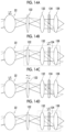
- FIGS. 14 A, 14 B, 14 C, and 14 D are diagrams showing aspects of adjustment in Cases 1 to 4
- FIG. 15 is a diagram showing an aspect of adjustment in Case 5.
- a plurality of elements may be integrally moved. In this way, which element should be adjusted differs depending on a situation, such as the relative position.
- the relative position detection unit 142 B (the processor 142 : see FIG. 12 ) can detect the positions of the field lens 122 , the lenses (the first lens 132 and the second lens 136 ) of the multispectral camera 130 , and the wavelength polarizing filter unit 134 by a photo interrupter, a magneto resistive sensor (MR sensor), or the like.
- a photo interrupter a magneto resistive sensor (MR sensor)
- FIGS. 16 and 17 are flowcharts showing a procedure of the adjustment of a conjugate relationship. A case where a conjugate relationship is adjusted mainly using the movement of the field lens 122 is shown in these flowcharts. These flowcharts will be described including both processing performed by the processor and an adjustment made by a user.
- a user mounts the field lens unit 120 and the multispectral camera 130 on an image side of the optical system 20 (another optical system) (Step S 100 ), and adjusts the optical axes of the optical system 20 , the field lens unit 120 , and the multispectral camera 130 .
- the image acquisition unit 142 A (processor 142 ) generates a plurality of images (spectral images), which correspond to the wavelength ranges of the optical filters 138 A to 138 D (a plurality of optical filters), respectively, on the basis of a plurality of image signals output from the imaging element 138 (Step S 120 : imaging step).
- the image acquisition unit 142 A performs interference removal processing to generate image data corresponding to the respective wavelength ranges.
- any one (for example, the aperture region 135 D) of the aperture regions 135 A to 135 D is shielded, three aperture regions 135 A to 135 C are used (that is, images corresponding to three wavelength ranges ⁇ 1 to ⁇ 3 are acquired).
- Ratios (interference ratios) at which lights having the respective wavelength ranges ⁇ 1 to ⁇ 3 and emitted from the imaging device 100 are received by the respective pixels can be uniquely determined from the setting of the wavelength ranges ⁇ 1 to ⁇ 3 of lights transmitted by the optical filters 138 A to 138 C, the setting of the polarization directions of lights transmitted by the polarizing filters 139 A to 139 C, and the setting of the polarization directions (four directions) of lights received by the respective pixels of the imaging element 138 ; and can be obtained in advance.
- the image acquisition unit 142 A can calculate the interference ratios from a plurality of images, which are acquired in a state where any one of a plurality of shielding members is inserted into the lens barrel 121 , using the plurality of shielding members that shield aperture regions other than a specific aperture region among a plurality of aperture regions.
- the image acquisition unit 142 A calculates coefficient groups (the respective elements of an interference removal matrix) for interference removal processing from these images, and stores these coefficient groups in the flash memory 144 .
- the image acquisition unit 142 A calculates pixel signals corresponding to the respective wavelength ranges ⁇ 1 to ⁇ 3 from pixel signals obtained from the respective pixels, and generates images corresponding to the respective wavelength ranges ⁇ 1 to ⁇ 3 (images from which interference has been removed, spectral images) using the coefficient groups acquired from the flash memory 144 .
- the images corresponding to the respective wavelength ranges ⁇ 1 to ⁇ 3 are output to the outside and stored in the storage device (not shown) as necessary.
- the display controller 142 D displays the spectral images on the display device 300 (display device) (Step S 125 : imaging step).
- the display of the spectral images and the adjustment of a conjugate relationship based on the light and darkness information of the spectral images may be performed for all wavelength ranges, or may be performed for some wavelength ranges.
- the image support information generation unit 142 C (processor) generates information (image support information) required for the adjustment of a conjugate relationship on the basis of the light and darkness information (light amount distribution) of at least one spectral image obtained from the multispectral camera 130 (Step S 130 : generation step).
- the image support information may include, for example, at least one of the attachment and detachment or exchange of the mount adapter 110 between the optical system 20 (another optical system) and the multispectral camera 130 , the exchange of the field lens unit 120 and/or the multispectral camera 130 , the forward or backward moving direction of the field lens 122 , the forward or backward moving direction of the first lens 132 and/or the second lens 136 , the forward or backward moving direction of the wavelength polarizing filter unit 134 , and the exchange of the wavelength polarizing filter unit 134 (alternatively, the exchange of the optical filters 138 A to 138 D).
- the image support information generation unit 142 C can generate the above-mentioned image support information on the basis of a direction of the aperture region and the light and darkness information of the spectral image. Specifically, as described above with reference to FIGS. 8 A, 8 B, 8 C, 8 D, 8 E, 8 F , and the like, the image support information can be generated using the fact that the centroids of the aperture regions 135 A to 135 D are different from the centroid 135 G of all the aperture regions.
- FIGS. 18 A, 18 B, and 18 C are conceptual diagrams showing a relationship between the direction of the aperture region and the light and darkness information of the spectral image.
- the optical filters in this case, the optical filters 138 B to 138 D disposed in the aperture regions 135 B to 135 D), which are disposed in the aperture regions other than the aperture region (for example, the aperture region 135 A) corresponding to the wavelength range, block (at least a part of) lights having the wavelength ranges other than the “specific wavelength range”. Accordingly, the optical filters act like stops for a light having “specific wavelength range” in the multispectral camera 130 .
- An image 133 is an image of the wavelength polarizing filter unit 134 that is formed by the first lens 132 (an incident pupil of the multispectral camera 130 ).
- FIG. 18 A shows a state where rays (an upper ray 150 , a main ray 152 , and a lower ray 154 ) transmitted through the field lens 122 are not blocked by “stop” for such a specific wavelength range (a short thick line in FIG. 18 A ; indicated by 134 that is a reference numeral of the wavelength polarizing filter unit) (vignetting does not occur).
- a specific wavelength range a short thick line in FIG. 18 A ; indicated by 134 that is a reference numeral of the wavelength polarizing filter unit
- the image support information can be generated in consideration of a relationship between the direction of such an aperture region and the light and darkness information of the spectral image. For example, since it is considered that a case where an upper side in the spectral image is bright and a lower side in the spectral image is dark is the state shown in FIG. 18 B , it is possible to adjust the conjugate relationship of a pupil to make the light amount distribution of the spectral image close to a uniform state by lowering the field lens 122 to the rear side (image side) to make a state close to the state shown in FIG. 18 A .
- the display controller 142 D displays (outputs) the image support information (in the above-mentioned example, the moving direction of the field lens 122 ), which is generated in this way, on the display device 300 (Step S 140 : output step).
- the display controller 142 D can display (output) a message “Please lower the field lens to the rear side” (a message showing the direction of the field lens 122 ) on the display device 300 in the above-mentioned example.
- the display controller 142 D may display (output) the moving direction (a forward movement or alternation) with a symbol, such as an arrow, instead of or in addition to displaying such a message (image support information) with letters.
- the display controller 142 D may display (output) an adjustment procedure serving as the image support information.
- the display device 300 displays at least one of the image support information or an adjustment procedure serving as the image support information according to an output from the display controller 142 D.
- a user can lower the field lens 122 to the rear side (move the field lens 122 backward in the direction of the optical axis L) according to the image support information (Step S 150 ).
- the image acquisition unit 142 A and the display controller 142 D (processor) display an image (spectral image), which is in a state after movement, on the display device 300 (Step S 160 : display step).
- the image support information generation unit 142 C determines whether or not the brightness of the image in a state after movement is equal to or higher than a threshold value (Step S 170 : brightness determination step and output step). In a case where a determination is positive (that is, in a case where the image is bright to have a brightness equal to or higher than the threshold value and vignetting is reduced), the processing ends.
- the image support information generation unit 142 C can employ, for example, “the sum of luminance values of the entire screen in a case where the maximum luminance of an image is standardized as 1” or “the inverse number of a distance from the center of the screen to the position of the centroid of luminance values” as the definition of “brightness”.
- the image support information generation unit 142 C and the display controller 142 D may display image support information, which indicates that the adjustment of a conjugate relationship ends, on the display device 300 in a case where the determination in Step S 170 is positive and the processing ends.
- Step S 170 determines whether or not the image is brightened by movement (Step S 180 : brightness determination step and output step). In a case where this determination is negative, the image support information generation unit 142 C and the display controller 142 D generate a message prompting a user to reverse the moving direction of the field lens 122 as the image support information and displays the message on the display device 300 (Step S 190 : generation step and output step). In Step S 195 , the image support information generation unit 142 C sets brightness obtained after movement as new brightness (brightness determination step, generation step, and output step), and returns to Step S 140 . In the example shown in FIGS. 16 and 17 , as described above, a conjugate relationship can be adjusted in the same manner as in a case where a focus lens is driven by “hill climbing method” in a general camera system.
- the imaging system 10 imaging device 100
- the adjustment method, and the adjustment program according to the first embodiment since a conjugate relationship can be adjusted in this way, multispectral images having good image quality can be acquired.
- FIG. 19 is a table showing an influence of the shapes of the aperture regions on the adjustment of a conjugate relationship.
- features related to the movement of the field lens are summarized in the column of “parameters related to the movement of the field lens”
- features related to the attachment and detachment and exchange of the field lens are summarized in the column of “attachability/detachability”
- basic features in a case where the field lens is used in combination are summarized in the column of “others”.
- an influence on the adjustment of a conjugate relationship varies depending on the shapes of the aperture regions.
- the centroids of the plurality of aperture regions are different from each other (the respective aperture regions are arranged asymmetrically with respect to the centroid of all the aperture regions). For this reason, a reduction in the amount of light at a peripheral portion and the moving distance of the field lens is increased in this case as compared to a case where the centroids of the plurality of aperture regions coincide with each other (for example, a case where the plurality of aperture regions have concentric circular shapes).
- the centroids of the aperture regions are different from each other, it is easy to discriminate the moving direction of the field lens as in an example to be described later. Further, the attachment and detachment of the field lens or an applicable F-Number also depends on the shapes of the aperture regions.
- the shapes of the aperture regions affect the adjustment of a conjugate relationship as described above, but the amount of reduction in the amount of light at a peripheral portion (the degree of vignetting) also affects the adjustment of a conjugate relationship. Specifically, in a case where a reduction in the amount of light at a peripheral portion is significant (vignetting is significant), it is necessary to roughly adjust a conjugate relationship (to significantly change a conjugate relationship). Accordingly, it is preferable that field lenses and/or multispectral cameras are attached and detached (field lenses and/or multispectral cameras having different sizes, focal lengths, or the like are mounted).
- the image support information generation unit 142 C and the display controller 142 D can generate and display image support information in consideration of such circumstances.
- FIGS. 20 A , 20 B 1 , 20 B 2 , 20 B 3 , 20 B 4 , 20 C 1 , 20 C 2 , 20 C 3 , and 20 C 4 are diagrams showing specific examples of the adjustment of a conjugate relationship in which the shapes of aperture regions are considered (a case where the field lens 122 is moved).
- aperture regions 160 A to 160 D (a plurality of aperture regions; forming an aperture region 160 as a whole) have a fan shape, and centroids of the respective aperture regions 160 A to 160 D are different from each other.
- each of the other aperture regions 160 A, 160 C, and 160 D acts as a kind of “stop” or “shielding member” as described above (it is assumed that optical filters having at least a part of wavelength ranges different from each other are mounted in the respective aperture regions).
- the image support information generation unit 142 C and the display controller 142 D (processor) generate information (image support information) prompting a user to increase a distance between the field lens 122 and the multispectral camera 130 (to move the field lens 122 forward) (generation step and output step), and display the information on the display device 300 (output step).
- FIG. 20 B 2 see FIGS. 18 A, 18 B, and 18 C .
- the image support information generation unit 142 C and the display controller 142 D (processor) generate information (image support information) prompting a user to increase a distance between the field lens 122 and the multispectral camera 130 (to move the field lens 122 forward) (generation step and output step), and display the information on the display device 300 (output step).
- FIG. 20 B 3 shows an example of a spectral image in a state where a user has moved the field lens 122 on the basis of the image support information, but a dark region still remains on the right side in the image in this example. Accordingly, the image support information generation unit 142 C and the display controller 142 D generate information prompting a user to increase a distance between the field lens 122 and the multispectral camera 130 again, and display the information on the display device 300 .
- FIG. 20 B 4 shows an example of a spectral image in a state where a user has moved the field lens again. Since a brightness is equal to or higher than a threshold value and light and darkness distribution is reduced, the processing ends.
- FIG. 20 C 1 is a diagram showing the aperture region 160 D of which the left side is open, and a right side in a spectral image is bright as shown in FIG. 20 C 2 in this case.
- the image support information generation unit 142 C and the display controller 142 D generate information (image support information) prompting a user to increase a distance between the field lens 122 and the multispectral camera 130 as in FIGS. 20 B 2 to 20 B 4 even in this case (generation step and output step), and display the information on the display device 300 (output step).
- the processing ends.
- multispectral images having good image quality can be acquired as described above.
- FIG. 21 is a diagram showing an aspect of connection to a microscope 30 (an aspect of “another optical system”).
- the microscope 30 comprises an optical system including an objective lens 32 , and a user can observe a specimen or the like placed on a stage 34 via an eyepiece portion 36 .
- the microscope 30 is provided with a camera-connecting part 38 , and the imaging device 100 (an aspect of the imaging device according to the embodiment of the present invention) can be connected to the camera-connecting part 38 .
- a part of luminous flux from the specimen or the like is guided to the imaging device 100 through the camera-connecting part 38 , and a conjugate relationship of a pupil is adjusted by the imaging device 100 as described above in the first embodiment, so that multispectral images having good image quality can be acquired.
- the processing of the adjustment method is performed by the processor 142 and a computer 330 (processor), and an acquired image can be displayed on the display device 300 .
- a user can perform operations required for the processing via the operation unit 320 .
- the above-mentioned imaging device body 140 may be connected to the microscope 30 , or may be formed integrally with the computer 330 as shown in FIG. 21 .
- FIG. 22 is a diagram showing an aspect of connection to a zooming optical system. Even in this case, a conjugate relationship of a pupil is adjusted by the imaging device 100 in the same manner as the first embodiment or the aspect of FIG. 21 , so that multispectral images having good image quality can be acquired.
- the polarizing filters 139 A to 139 D provided in the wavelength polarizing filter unit 134 and the polarizing filter elements 214 A to 214 D provided in the imaging element 138 receive light having passed through any of the aperture regions.
- the present invention is not limited to such an aspect.
- a conjugate relationship can be adjusted using the movement or the like of the field lens even without using polarization. As a result, multispectral image having good image quality can be acquired.
- an optical system 20 and an imaging device 101 are connected to each other via the mount adapter 110 (adjustment mechanism) or the like and the respective elements are connected to each other even in the imaging device 100 .
- these elements do not necessarily need to be mechanically connected to each other in the present invention.
- an optical system 20 (another optical system) and an imaging device 101 (imaging device) can be disposed apart from each other as in an imaging system 11 shown in FIG. 23
- a field lens unit 120 and a multispectral camera 130 can be disposed apart from each other even in the imaging device 101 .
- each of the optical system 20 , the field lens unit 120 , and the multispectral camera 130 is held by a member (not shown), such as a tripod or a guide rail, or is placed on an adjustment table.
- the adjustment of an interval between the respective element and the forward or backward movement, the attachment and detachment, the exchange, and the like of the lenses can be performed as in the above-mentioned aspect. Accordingly, a conjugate relationship of a pupil can be adjusted, so that multispectral images having good image quality can be acquired. Even in the aspect shown in FIG. 23 , it is preferable that the optical axes of the respective elements coincide with each other before the capturing of multispectral images as described above in the first embodiment.
Landscapes
- Physics & Mathematics (AREA)
- General Physics & Mathematics (AREA)
- Optics & Photonics (AREA)
- Engineering & Computer Science (AREA)
- Multimedia (AREA)
- Signal Processing (AREA)
- Spectroscopy & Molecular Physics (AREA)
- Chemical & Material Sciences (AREA)
- Human Computer Interaction (AREA)
- Analytical Chemistry (AREA)
- Studio Devices (AREA)
- Blocking Light For Cameras (AREA)
- Spectrometry And Color Measurement (AREA)
- Lens Barrels (AREA)
- Camera Bodies And Camera Details Or Accessories (AREA)
- Polarising Elements (AREA)
Applications Claiming Priority (3)
| Application Number | Priority Date | Filing Date | Title |
|---|---|---|---|
| JP2020-127274 | 2020-07-28 | ||
| JP2020127274 | 2020-07-28 | ||
| PCT/JP2021/027296 WO2022024917A1 (ja) | 2020-07-28 | 2021-07-21 | 撮像装置、調整方法、及び調整プログラム |
Related Parent Applications (1)
| Application Number | Title | Priority Date | Filing Date |
|---|---|---|---|
| PCT/JP2021/027296 Continuation WO2022024917A1 (ja) | 2020-07-28 | 2021-07-21 | 撮像装置、調整方法、及び調整プログラム |
Publications (2)
| Publication Number | Publication Date |
|---|---|
| US20230204950A1 US20230204950A1 (en) | 2023-06-29 |
| US12181663B2 true US12181663B2 (en) | 2024-12-31 |
Family
ID=80036839
Family Applications (1)
| Application Number | Title | Priority Date | Filing Date |
|---|---|---|---|
| US18/153,359 Active 2042-01-27 US12181663B2 (en) | 2020-07-28 | 2023-01-12 | Imaging device, adjustment method, and adjustment program |
Country Status (3)
| Country | Link |
|---|---|
| US (1) | US12181663B2 (https=) |
| JP (1) | JP7522198B2 (https=) |
| WO (1) | WO2022024917A1 (https=) |
Families Citing this family (2)
| Publication number | Priority date | Publication date | Assignee | Title |
|---|---|---|---|---|
| JPWO2023157396A1 (https=) * | 2022-02-15 | 2023-08-24 | ||
| WO2024042783A1 (ja) * | 2022-08-22 | 2024-02-29 | 富士フイルム株式会社 | 画像処理装置、画像処理方法、及びプログラム |
Citations (5)
| Publication number | Priority date | Publication date | Assignee | Title |
|---|---|---|---|---|
| JP2004219397A (ja) | 2002-11-20 | 2004-08-05 | Nikon Corp | 光学系、それを備えた固体撮像素子照明装置及び固体撮像素子の検査方法 |
| JP2008064933A (ja) | 2006-09-06 | 2008-03-21 | Opcell Co Ltd | 光学ユニット |
| JP2019082412A (ja) | 2017-10-31 | 2019-05-30 | 株式会社ニコン | 撮像装置 |
| US20200117073A1 (en) * | 2018-10-16 | 2020-04-16 | Canon Kabushiki Kaisha | Optical apparatus and imaging system including the same |
| WO2021085368A1 (ja) * | 2019-10-30 | 2021-05-06 | 富士フイルム株式会社 | 撮像装置、撮像光学系及び撮像方法 |
Family Cites Families (1)
| Publication number | Priority date | Publication date | Assignee | Title |
|---|---|---|---|---|
| US9395516B2 (en) * | 2012-05-28 | 2016-07-19 | Nikon Corporation | Imaging device |
-
2021
- 2021-07-21 WO PCT/JP2021/027296 patent/WO2022024917A1/ja not_active Ceased
- 2021-07-21 JP JP2022540241A patent/JP7522198B2/ja active Active
-
2023
- 2023-01-12 US US18/153,359 patent/US12181663B2/en active Active
Patent Citations (5)
| Publication number | Priority date | Publication date | Assignee | Title |
|---|---|---|---|---|
| JP2004219397A (ja) | 2002-11-20 | 2004-08-05 | Nikon Corp | 光学系、それを備えた固体撮像素子照明装置及び固体撮像素子の検査方法 |
| JP2008064933A (ja) | 2006-09-06 | 2008-03-21 | Opcell Co Ltd | 光学ユニット |
| JP2019082412A (ja) | 2017-10-31 | 2019-05-30 | 株式会社ニコン | 撮像装置 |
| US20200117073A1 (en) * | 2018-10-16 | 2020-04-16 | Canon Kabushiki Kaisha | Optical apparatus and imaging system including the same |
| WO2021085368A1 (ja) * | 2019-10-30 | 2021-05-06 | 富士フイルム株式会社 | 撮像装置、撮像光学系及び撮像方法 |
Non-Patent Citations (3)
| Title |
|---|
| "International Search Report (Form PCT/ISA/210) of PCT/JP2021/027296", mailed on Oct. 12, 2021, with English translation thereof, pp. 1-5. |
| "Notice of Reasons for Refusal of Japan Counterpart Application", issued on Jan. 12, 2024, with English translation thereof, p. 1-p. 8. |
| "Written Opinion of the International Searching Authority (Form PCT/ISA/237) of PCT/JP2021/027296", mailed on Oct. 12, 2021, with English translation thereof, pp. 1-8. |
Also Published As
| Publication number | Publication date |
|---|---|
| WO2022024917A1 (ja) | 2022-02-03 |
| JPWO2022024917A1 (https=) | 2022-02-03 |
| US20230204950A1 (en) | 2023-06-29 |
| JP7522198B2 (ja) | 2024-07-24 |
Similar Documents
| Publication | Publication Date | Title |
|---|---|---|
| US10212334B2 (en) | Focusing adjustment apparatus and focusing adjustment method | |
| US9201288B2 (en) | Image processing apparatus with blur correcting function | |
| JP5276374B2 (ja) | 焦点検出装置 | |
| JP6584149B2 (ja) | 撮像装置 | |
| CN104041006B (zh) | 图像生成方法以及图像生成设备 | |
| CN104956661B (zh) | 图像拾取装置、图像处理装置、图像处理方法 | |
| US8427570B2 (en) | Focus position control apparatus and camera | |
| US12181663B2 (en) | Imaging device, adjustment method, and adjustment program | |
| JP2009217074A (ja) | 焦点検出装置 | |
| US10674074B2 (en) | Image processing apparatus, image pickup apparatus, image processing method, and non-transitory computer-readable storage medium for generating an image based on a plurality of parallax images | |
| CN108886568A (zh) | 光学装置 | |
| WO2013027507A1 (ja) | 撮像装置 | |
| JP2015194736A (ja) | 撮像装置およびその制御方法 | |
| JP2014215436A (ja) | 撮像装置、その制御方法、および制御プログラム | |
| JP2014130231A (ja) | 撮像装置、その制御方法、および制御プログラム | |
| US10200622B2 (en) | Image processing method, image processing apparatus, and imaging apparatus | |
| US11122196B2 (en) | Image processing apparatus | |
| US9591204B2 (en) | Focus detecting unit, focus detecting method, image pickup apparatus, and image pickup system | |
| JP2016063391A (ja) | 撮像装置、表示装置、及び、電子機器 | |
| JP5793210B2 (ja) | 撮像装置 | |
| JP7337566B2 (ja) | 撮像装置、画像処理方法、およびプログラム | |
| TWI451128B (zh) | 掃描系統 | |
| JP2017102240A (ja) | 画像処理装置および画像処理方法、撮像装置、プログラム | |
| JP6331279B2 (ja) | 撮像装置、撮像方法およびプログラム | |
| JP2010187265A (ja) | 撮像装置および撮像装置の制御方法 |
Legal Events
| Date | Code | Title | Description |
|---|---|---|---|
| FEPP | Fee payment procedure |
Free format text: ENTITY STATUS SET TO UNDISCOUNTED (ORIGINAL EVENT CODE: BIG.); ENTITY STATUS OF PATENT OWNER: LARGE ENTITY |
|
| AS | Assignment |
Owner name: FUJIFILM CORPORATION, JAPAN Free format text: ASSIGNMENT OF ASSIGNORS INTEREST;ASSIGNORS:OKADA, KAZUYOSHI;KISHINE, YASUNOBU;KAWANAGO, ATSUSHI;REEL/FRAME:062366/0363 Effective date: 20221108 |
|
| STPP | Information on status: patent application and granting procedure in general |
Free format text: DOCKETED NEW CASE - READY FOR EXAMINATION |
|
| STPP | Information on status: patent application and granting procedure in general |
Free format text: NOTICE OF ALLOWANCE MAILED -- APPLICATION RECEIVED IN OFFICE OF PUBLICATIONS |
|
| STPP | Information on status: patent application and granting procedure in general |
Free format text: PUBLICATIONS -- ISSUE FEE PAYMENT VERIFIED |
|
| STCF | Information on status: patent grant |
Free format text: PATENTED CASE |