US12087911B2 - Method of manufacturing a solid electrolyte membrane - Google Patents
Method of manufacturing a solid electrolyte membrane Download PDFInfo
- Publication number
- US12087911B2 US12087911B2 US17/594,650 US202017594650A US12087911B2 US 12087911 B2 US12087911 B2 US 12087911B2 US 202017594650 A US202017594650 A US 202017594650A US 12087911 B2 US12087911 B2 US 12087911B2
- Authority
- US
- United States
- Prior art keywords
- solid electrolyte
- woven fabric
- electrolyte membrane
- solid
- manufacturing
- Prior art date
- Legal status (The legal status is an assumption and is not a legal conclusion. Google has not performed a legal analysis and makes no representation as to the accuracy of the status listed.)
- Active, expires
Links
Images


Classifications
-
- B—PERFORMING OPERATIONS; TRANSPORTING
- B29—WORKING OF PLASTICS; WORKING OF SUBSTANCES IN A PLASTIC STATE IN GENERAL
- B29C—SHAPING OR JOINING OF PLASTICS; SHAPING OF MATERIAL IN A PLASTIC STATE, NOT OTHERWISE PROVIDED FOR; AFTER-TREATMENT OF THE SHAPED PRODUCTS, e.g. REPAIRING
- B29C48/00—Extrusion moulding, i.e. expressing the moulding material through a die or nozzle which imparts the desired form; Apparatus therefor
- B29C48/25—Component parts, details or accessories; Auxiliary operations
- B29C48/36—Means for plasticising or homogenising the moulding material or forcing it through the nozzle or die
-
- D—TEXTILES; PAPER
- D01—NATURAL OR MAN-MADE THREADS OR FIBRES; SPINNING
- D01D—MECHANICAL METHODS OR APPARATUS IN THE MANUFACTURE OF ARTIFICIAL FILAMENTS, THREADS, FIBRES, BRISTLES OR RIBBONS
- D01D5/00—Formation of filaments, threads, or the like
- D01D5/0007—Electro-spinning
- D01D5/0015—Electro-spinning characterised by the initial state of the material
- D01D5/0023—Electro-spinning characterised by the initial state of the material the material being a polymer melt
-
- D—TEXTILES; PAPER
- D01—NATURAL OR MAN-MADE THREADS OR FIBRES; SPINNING
- D01D—MECHANICAL METHODS OR APPARATUS IN THE MANUFACTURE OF ARTIFICIAL FILAMENTS, THREADS, FIBRES, BRISTLES OR RIBBONS
- D01D5/00—Formation of filaments, threads, or the like
- D01D5/0007—Electro-spinning
- D01D5/0015—Electro-spinning characterised by the initial state of the material
- D01D5/003—Electro-spinning characterised by the initial state of the material the material being a polymer solution or dispersion
- D01D5/0038—Electro-spinning characterised by the initial state of the material the material being a polymer solution or dispersion the fibre formed by solvent evaporation, i.e. dry electro-spinning
-
- D—TEXTILES; PAPER
- D01—NATURAL OR MAN-MADE THREADS OR FIBRES; SPINNING
- D01D—MECHANICAL METHODS OR APPARATUS IN THE MANUFACTURE OF ARTIFICIAL FILAMENTS, THREADS, FIBRES, BRISTLES OR RIBBONS
- D01D5/00—Formation of filaments, threads, or the like
- D01D5/0007—Electro-spinning
- D01D5/0061—Electro-spinning characterised by the electro-spinning apparatus
- D01D5/0076—Electro-spinning characterised by the electro-spinning apparatus characterised by the collecting device, e.g. drum, wheel, endless belt, plate or grid
- D01D5/0084—Coating by electro-spinning, i.e. the electro-spun fibres are not removed from the collecting device but remain integral with it, e.g. coating of prostheses
-
- D—TEXTILES; PAPER
- D01—NATURAL OR MAN-MADE THREADS OR FIBRES; SPINNING
- D01D—MECHANICAL METHODS OR APPARATUS IN THE MANUFACTURE OF ARTIFICIAL FILAMENTS, THREADS, FIBRES, BRISTLES OR RIBBONS
- D01D5/00—Formation of filaments, threads, or the like
- D01D5/0007—Electro-spinning
- D01D5/0061—Electro-spinning characterised by the electro-spinning apparatus
- D01D5/0092—Electro-spinning characterised by the electro-spinning apparatus characterised by the electrical field, e.g. combined with a magnetic fields, using biased or alternating fields
-
- D—TEXTILES; PAPER
- D04—BRAIDING; LACE-MAKING; KNITTING; TRIMMINGS; NON-WOVEN FABRICS
- D04H—MAKING TEXTILE FABRICS, e.g. FROM FIBRES OR FILAMENTARY MATERIAL; FABRICS MADE BY SUCH PROCESSES OR APPARATUS, e.g. FELTS, NON-WOVEN FABRICS; COTTON-WOOL; WADDING ; NON-WOVEN FABRICS FROM STAPLE FIBRES, FILAMENTS OR YARNS, BONDED WITH AT LEAST ONE WEB-LIKE MATERIAL DURING THEIR CONSOLIDATION
- D04H1/00—Non-woven fabrics formed wholly or mainly of staple fibres or like relatively short fibres
- D04H1/70—Non-woven fabrics formed wholly or mainly of staple fibres or like relatively short fibres characterised by the method of forming fleeces or layers, e.g. reorientation of fibres
- D04H1/72—Non-woven fabrics formed wholly or mainly of staple fibres or like relatively short fibres characterised by the method of forming fleeces or layers, e.g. reorientation of fibres the fibres being randomly arranged
- D04H1/728—Non-woven fabrics formed wholly or mainly of staple fibres or like relatively short fibres characterised by the method of forming fleeces or layers, e.g. reorientation of fibres the fibres being randomly arranged by electro-spinning
-
- H—ELECTRICITY
- H01—ELECTRIC ELEMENTS
- H01M—PROCESSES OR MEANS, e.g. BATTERIES, FOR THE DIRECT CONVERSION OF CHEMICAL ENERGY INTO ELECTRICAL ENERGY
- H01M10/00—Secondary cells; Manufacture thereof
- H01M10/05—Accumulators with non-aqueous electrolyte
- H01M10/052—Li-accumulators
- H01M10/0525—Rocking-chair batteries, i.e. batteries with lithium insertion or intercalation in both electrodes; Lithium-ion batteries
-
- H—ELECTRICITY
- H01—ELECTRIC ELEMENTS
- H01M—PROCESSES OR MEANS, e.g. BATTERIES, FOR THE DIRECT CONVERSION OF CHEMICAL ENERGY INTO ELECTRICAL ENERGY
- H01M10/00—Secondary cells; Manufacture thereof
- H01M10/05—Accumulators with non-aqueous electrolyte
- H01M10/056—Accumulators with non-aqueous electrolyte characterised by the materials used as electrolytes, e.g. mixed inorganic/organic electrolytes
- H01M10/0561—Accumulators with non-aqueous electrolyte characterised by the materials used as electrolytes, e.g. mixed inorganic/organic electrolytes the electrolyte being constituted of inorganic materials only
- H01M10/0562—Solid materials
-
- H—ELECTRICITY
- H01—ELECTRIC ELEMENTS
- H01M—PROCESSES OR MEANS, e.g. BATTERIES, FOR THE DIRECT CONVERSION OF CHEMICAL ENERGY INTO ELECTRICAL ENERGY
- H01M10/00—Secondary cells; Manufacture thereof
- H01M10/05—Accumulators with non-aqueous electrolyte
- H01M10/058—Construction or manufacture
- H01M10/0585—Construction or manufacture of accumulators having only flat construction elements, i.e. flat positive electrodes, flat negative electrodes and flat separators
-
- H—ELECTRICITY
- H01—ELECTRIC ELEMENTS
- H01M—PROCESSES OR MEANS, e.g. BATTERIES, FOR THE DIRECT CONVERSION OF CHEMICAL ENERGY INTO ELECTRICAL ENERGY
- H01M6/00—Primary cells; Manufacture thereof
- H01M6/14—Cells with non-aqueous electrolyte
- H01M6/18—Cells with non-aqueous electrolyte with solid electrolyte
- H01M6/187—Solid electrolyte characterised by the form
-
- H—ELECTRICITY
- H01—ELECTRIC ELEMENTS
- H01M—PROCESSES OR MEANS, e.g. BATTERIES, FOR THE DIRECT CONVERSION OF CHEMICAL ENERGY INTO ELECTRICAL ENERGY
- H01M6/00—Primary cells; Manufacture thereof
- H01M6/14—Cells with non-aqueous electrolyte
- H01M6/18—Cells with non-aqueous electrolyte with solid electrolyte
- H01M6/188—Processes of manufacture
-
- B—PERFORMING OPERATIONS; TRANSPORTING
- B29—WORKING OF PLASTICS; WORKING OF SUBSTANCES IN A PLASTIC STATE IN GENERAL
- B29D—PRODUCING PARTICULAR ARTICLES FROM PLASTICS OR FROM SUBSTANCES IN A PLASTIC STATE
- B29D99/00—Subject matter not provided for in other groups of this subclass
- B29D99/005—Producing membranes
-
- B—PERFORMING OPERATIONS; TRANSPORTING
- B29—WORKING OF PLASTICS; WORKING OF SUBSTANCES IN A PLASTIC STATE IN GENERAL
- B29K—INDEXING SCHEME ASSOCIATED WITH SUBCLASSES B29B, B29C OR B29D, RELATING TO MOULDING MATERIALS OR TO MATERIALS FOR MOULDS, REINFORCEMENTS, FILLERS OR PREFORMED PARTS, e.g. INSERTS
- B29K2023/00—Use of polyalkenes or derivatives thereof as moulding material
- B29K2023/04—Polymers of ethylene
- B29K2023/06—PE, i.e. polyethylene
-
- B—PERFORMING OPERATIONS; TRANSPORTING
- B29—WORKING OF PLASTICS; WORKING OF SUBSTANCES IN A PLASTIC STATE IN GENERAL
- B29K—INDEXING SCHEME ASSOCIATED WITH SUBCLASSES B29B, B29C OR B29D, RELATING TO MOULDING MATERIALS OR TO MATERIALS FOR MOULDS, REINFORCEMENTS, FILLERS OR PREFORMED PARTS, e.g. INSERTS
- B29K2023/00—Use of polyalkenes or derivatives thereof as moulding material
- B29K2023/10—Polymers of propylene
- B29K2023/12—PP, i.e. polypropylene
-
- B—PERFORMING OPERATIONS; TRANSPORTING
- B29—WORKING OF PLASTICS; WORKING OF SUBSTANCES IN A PLASTIC STATE IN GENERAL
- B29K—INDEXING SCHEME ASSOCIATED WITH SUBCLASSES B29B, B29C OR B29D, RELATING TO MOULDING MATERIALS OR TO MATERIALS FOR MOULDS, REINFORCEMENTS, FILLERS OR PREFORMED PARTS, e.g. INSERTS
- B29K2401/00—Use of cellulose, modified cellulose or cellulose derivatives, e.g. viscose, as filler
-
- B—PERFORMING OPERATIONS; TRANSPORTING
- B29—WORKING OF PLASTICS; WORKING OF SUBSTANCES IN A PLASTIC STATE IN GENERAL
- B29L—INDEXING SCHEME ASSOCIATED WITH SUBCLASS B29C, RELATING TO PARTICULAR ARTICLES
- B29L2031/00—Other particular articles
- B29L2031/755—Membranes, diaphragms
-
- D—TEXTILES; PAPER
- D10—INDEXING SCHEME ASSOCIATED WITH SUBLASSES OF SECTION D, RELATING TO TEXTILES
- D10B—INDEXING SCHEME ASSOCIATED WITH SUBLASSES OF SECTION D, RELATING TO TEXTILES
- D10B2321/00—Fibres made from polymers obtained by reactions only involving carbon-to-carbon unsaturated bonds
- D10B2321/02—Fibres made from polymers obtained by reactions only involving carbon-to-carbon unsaturated bonds polyolefins
- D10B2321/021—Fibres made from polymers obtained by reactions only involving carbon-to-carbon unsaturated bonds polyolefins polyethylene
-
- D—TEXTILES; PAPER
- D10—INDEXING SCHEME ASSOCIATED WITH SUBLASSES OF SECTION D, RELATING TO TEXTILES
- D10B—INDEXING SCHEME ASSOCIATED WITH SUBLASSES OF SECTION D, RELATING TO TEXTILES
- D10B2321/00—Fibres made from polymers obtained by reactions only involving carbon-to-carbon unsaturated bonds
- D10B2321/02—Fibres made from polymers obtained by reactions only involving carbon-to-carbon unsaturated bonds polyolefins
- D10B2321/022—Fibres made from polymers obtained by reactions only involving carbon-to-carbon unsaturated bonds polyolefins polypropylene
-
- H—ELECTRICITY
- H01—ELECTRIC ELEMENTS
- H01M—PROCESSES OR MEANS, e.g. BATTERIES, FOR THE DIRECT CONVERSION OF CHEMICAL ENERGY INTO ELECTRICAL ENERGY
- H01M2300/00—Electrolytes
- H01M2300/0017—Non-aqueous electrolytes
- H01M2300/0065—Solid electrolytes
- H01M2300/0068—Solid electrolytes inorganic
-
- H—ELECTRICITY
- H01—ELECTRIC ELEMENTS
- H01M—PROCESSES OR MEANS, e.g. BATTERIES, FOR THE DIRECT CONVERSION OF CHEMICAL ENERGY INTO ELECTRICAL ENERGY
- H01M2300/00—Electrolytes
- H01M2300/0088—Composites
-
- Y—GENERAL TAGGING OF NEW TECHNOLOGICAL DEVELOPMENTS; GENERAL TAGGING OF CROSS-SECTIONAL TECHNOLOGIES SPANNING OVER SEVERAL SECTIONS OF THE IPC; TECHNICAL SUBJECTS COVERED BY FORMER USPC CROSS-REFERENCE ART COLLECTIONS [XRACs] AND DIGESTS
- Y02—TECHNOLOGIES OR APPLICATIONS FOR MITIGATION OR ADAPTATION AGAINST CLIMATE CHANGE
- Y02E—REDUCTION OF GREENHOUSE GAS [GHG] EMISSIONS, RELATED TO ENERGY GENERATION, TRANSMISSION OR DISTRIBUTION
- Y02E60/00—Enabling technologies; Technologies with a potential or indirect contribution to GHG emissions mitigation
- Y02E60/10—Energy storage using batteries
-
- Y—GENERAL TAGGING OF NEW TECHNOLOGICAL DEVELOPMENTS; GENERAL TAGGING OF CROSS-SECTIONAL TECHNOLOGIES SPANNING OVER SEVERAL SECTIONS OF THE IPC; TECHNICAL SUBJECTS COVERED BY FORMER USPC CROSS-REFERENCE ART COLLECTIONS [XRACs] AND DIGESTS
- Y02—TECHNOLOGIES OR APPLICATIONS FOR MITIGATION OR ADAPTATION AGAINST CLIMATE CHANGE
- Y02P—CLIMATE CHANGE MITIGATION TECHNOLOGIES IN THE PRODUCTION OR PROCESSING OF GOODS
- Y02P70/00—Climate change mitigation technologies in the production process for final industrial or consumer products
- Y02P70/50—Manufacturing or production processes characterised by the final manufactured product
Definitions
- the present invention relates to a method of manufacturing a solid electrolyte membrane, a method of manufacturing an all-solid-state battery, an apparatus for manufacturing a solid electrolyte membrane, and an apparatus for manufacturing an all-solid-state battery.
- LIB lithium batteries
- the LIB has at least three layers of a positive electrode, a separator, and a negative electrode, and is formed to have a structure in which these three layers are covered with an electrolyte.
- An organic solvent which is a flammable substance, is generally used as the electrolyte, but recently, an all-solid-state battery has been attracting attention in order to develop a battery with higher safety.
- an all-solid-state battery a flammable organic electrolytic solution is replaced with a non-flammable inorganic solid electrolyte or the like, and its safety is improved as compared with the conventional batteries. Also, in such an all-solid-state battery, further improvement is expected in terms of battery performance, and for example, higher energy density of the battery is expected.
- Patent Document 1 Japanese Unexamined Patent Application Publication No. 2010-250982 discloses a sheet for solid electrolyte obtained by molding the powder containing solid electrolyte glass particles containing Li, P, and S, wherein the standard deviations of the area ratios of the peaks obtained by the waveform separation of the peak present between 330 cm ⁇ 1 to 450 cm ⁇ 1 of the Raman spectrum measured repeatedly for the glass particles are all less than 4.0.
- Patent Document 2 Japanese Unexamined Patent Application Publication No. 2017-103146 discloses a technology related to a solid electrolyte sheet and a method of manufacturing the same that can give excellent energy density and output characteristics to an all-solid-state battery and make it possible to produce a large number of all-solid-state batteries by the continuous process.
- the solid electrolyte sheet includes a solid electrolyte and a support, the support has a plurality of through holes, and the solid electrolyte is filled in the through holes.
- the method of manufacturing the solid electrolyte sheet includes a step of filling a plurality of through holes formed on the support with the solid electrolyte, and a step of pressing the support in which the through holes are filled with the solid electrolyte.
- Patent Document 3 Japanese Unexamined Patent Application Publication No. 2018-204140 discloses a technology for fabricating a PET fiber web by the laser electrospinning (LES) method.
- Patent Document 1 Japanese Unexamined Patent Application Publication No. 2010-250982
- Patent Document 2 Japanese Unexamined Patent Application Publication No. 2017-103146
- Patent Document 3 Japanese Unexamined Patent Application Publication No. 2018-204140
- the solid electrolyte glass particle powder containing elements such as Li and others is molded to form a sheet, and this sheet is applied to a solid electrolyte.
- the electrical conduction in the solid electrolyte formed only of the powder material is made by the contact between powders, the contact area becomes small and the output characteristics tend to be inferior to those of the lithium battery using the electrolytic solution.
- a powder material it is difficult to form a thin film sheet composed of a layer made of a single material, and the manufacturing process tends to be complicated.
- the solid electrolyte sheet (thickness: 37 to 138 ⁇ m) is manufactured by filling a plurality of through holes having a square shape with a side of 200 to 800 ⁇ m, which is formed by a photo-etching method in a polyimide sheet-like support, with a solid electrolyte, and then performing the heating and pressurizing process with a press machine.
- a wet etching method using a chromium-based solvent is used when penetrating the polyimide sheet serving as a support, a harmful organic solvent is used, which poses serious cost and environmental problems.
- the solid electrolyte since the size of the opening is large and the specific gravity of the solid electrolyte is large, the solid electrolyte may gradually fall off from the sheet support in the case of binderless, and the durability tends to be low. Furthermore, since the solid electrolyte layer is thick, the resistance between electrodes becomes high.
- a method of manufacturing a solid electrolyte membrane described in an embodiment disclosed in this application includes: (a) a step of forming a non-woven fabric including a fiber made of a resin; (b) a step of applying a slurry containing solid electrolyte particles onto the non-woven fabric; (c) a step of drying the slurry on the non-woven fabric by a heater; and (d) a step of pressurizing the slurry on the non-woven fabric by a roller.
- a method of manufacturing an all-solid-state battery described in an embodiment disclosed in this application includes: (a) a step of forming a non-woven fabric including a fiber made of a resin; (b) a step of applying a slurry containing solid electrolyte particles onto the non-woven fabric; (c) a step of drying the slurry on the non-woven fabric by a heater; (d) a step of pressurizing the slurry on the non-woven fabric by a roller; (e) a step of forming a positive electrode member on one surface of the solid electrolyte membrane formed in the step (d); and (f) a step of forming a negative electrode member on the other surface of the solid electrolyte membrane.
- An apparatus for manufacturing a solid electrolyte membrane described in an embodiment disclosed in this application includes: an extruder; a non-woven fabric manufacturing machine; and an all-solid-state battery laminate manufacturing machine, the extruder kneads a resin while melting it, the non-woven fabric manufacturing machine forms a non-woven fabric by making the resin fibrous, and the all-solid-state battery laminate manufacturing machine forms a solid electrolyte membrane by applying a slurry containing solid electrolyte particles onto the non-woven fabric and drying and pressurizing the slurry.
- An apparatus for manufacturing an all-solid-state battery described in an embodiment disclosed in this application includes: an extruder; a non-woven fabric manufacturing machine; and an all-solid-state battery laminate manufacturing machine, the extruder kneads a resin while melting it, the non-woven fabric manufacturing machine forms a non-woven fabric by making the resin fibrous, and the all-solid-state battery laminate manufacturing machine (a) forms a solid electrolyte membrane by applying a slurry containing solid electrolyte particles onto the non-woven fabric and drying and pressurizing the slurry on the non-woven fabric and (b) forms a positive electrode member on one surface of the solid electrolyte membrane and forms a negative electrode member on the other surface of the solid electrolyte membrane.
- the method of manufacturing the solid electrolyte membrane described in the typical embodiment disclosed in this application it is possible to efficiently manufacture the solid electrolyte membrane having favorable characteristics.
- the method of manufacturing the all-solid-state battery described in the typical embodiment disclosed in this application it is possible to efficiently manufacture the all-solid-state battery having favorable characteristics.
- the apparatus for manufacturing the solid electrolyte membrane described in the typical embodiment disclosed in this application it is possible to efficiently manufacture the solid electrolyte membrane having favorable characteristics.
- the apparatus for manufacturing the all-solid-state battery described in the typical embodiment disclosed in this application it is possible to efficiently manufacture the all-solid-state battery having favorable characteristics.
- FIG. 1 is a cross-sectional view schematically showing a configuration of an all-solid-state battery according to an embodiment
- FIG. 2 is a diagram showing a manufacturing process of a solid electrolyte membrane according to the embodiment
- FIG. 3 is a cross-sectional view schematically showing a configuration of an all-solid-state battery according to a comparative example
- FIG. 4 is a diagram showing a manufacturing process of a solid electrolyte sheet of the all-solid-state battery according to the comparative example
- FIG. 5 is a schematic diagram showing a configuration of a laser electrospinning apparatus
- FIG. 6 is a diagram (photograph) showing a state of a nozzle tip at the time of forming a fiber web of HDPE;
- FIG. 7 is a SEM photograph of the fiber web of HDPE
- FIG. 8 is a diagram (photograph) showing a state of a nozzle tip at the time of forming a fiber web of CeNF-added HDPE;
- FIG. 9 is a SEM photograph of the fiber web of CeNF-added HDPE.
- FIG. 10 is a cross-sectional view showing a manufacturing process of an all-solid-state battery
- FIG. 11 is a schematic diagram showing a configuration of a manufacturing apparatus (system) according to the second embodiment
- FIG. 12 is a diagram showing a configuration of a twin-screw kneading extruder
- FIG. 13 is a diagram showing a configuration of a part of the extruder
- FIG. 14 is a diagram showing a configuration of a screw
- FIG. 15 is a diagram showing a configuration of a non-woven fabric manufacturing machine
- FIG. 16 is a diagram showing a configuration of an all-solid-state battery laminate manufacturing machine
- FIG. 17 is a diagram showing a configuration of an all-solid-state battery laminate manufacturing machine according to the application example 5;
- FIG. 18 is a diagram showing a configuration of an all-solid-state battery laminate manufacturing machine according to the application example 6;
- FIG. 19 is a diagram showing a configuration of an all-solid-state battery laminate manufacturing machine according to the application example 7.
- FIG. 20 is a diagram showing a configuration of an all-solid-state battery laminate manufacturing machine according to the application example 8.
- FIG. 1 is a cross-sectional view schematically showing a configuration of an all-solid-state battery according to an embodiment.
- This all-solid-state battery is a lithium ion secondary battery.
- the all-solid-state battery means a battery that does not include at least an electrolytic solution (liquid electrolyte).
- the lithium ion secondary battery according to the present embodiment includes a negative electrode 20 , a positive electrode 30 , and a solid electrolyte membrane (solid electrolyte layer) 40 arranged therebetween.
- the negative electrode 20 has a negative electrode mixture layer 20 A and a negative electrode current collector 20 B.
- the negative electrode mixture layer 20 A has a negative electrode active material 2 AP and a solid electrolyte material (solid electrolyte material for negative electrode). Further, the negative electrode mixture layer 20 A may have a negative electrode conductive assistant, a negative electrode binder, and the like.
- the negative electrode current collector 20 B is made of, for example, metal foil (for example, copper foil).
- the negative electrode active material 2 AP a material capable of occluding and releasing lithium, for example, graphite (natural graphite, artificial graphite, etc.) can be used.
- the negative electrode active material 2 AP is granular.
- the positive electrode 30 has a positive electrode mixture layer 30 A and a positive electrode current collector 30 B.
- the positive electrode mixture layer 30 A has a positive electrode active material 3 AP and a solid electrolyte material (solid electrolyte material for positive electrode). Further, the positive electrode mixture layer 30 A may have a positive electrode conductive assistant, a positive electrode binder, and the like.
- the positive electrode current collector 30 B is made of, for example, metal foil (for example, aluminum foil).
- the positive electrode active material 3 AP a material capable of occluding and releasing lithium, for example, an oxide containing lithium (LiCoO 2 , LiNiO 2 , LiMnO 2 , etc.) can be used.
- the positive electrode active material 3 AP is granular.
- the solid electrolyte membrane 40 is made of a solid electrolyte material.
- a material having Li ion conductivity can be used.
- the solid electrolyte material is granular.
- solid electrolyte material a sulfide-based solid electrolyte or an oxide-based solid electrolyte can be used.
- a sulfide-based solid electrolyte for example, a sulfide containing Li and P can be used.
- an oxide containing Li can be used as the oxide-based solid electrolyte.
- an oxide containing Li can be used as the oxide-based solid electrolyte.
- La 0.51 Li 0.34 TiO 2.94 , Li 1.3 Al 0.3 Ti 1.7 (PO 4 ) 3 , Li 7 La 3 Zr 2 O 12 , Li 2.9 P 03.3 N 0.46 , Li 3.6 Si 0.6 P 0.4 O 4 , Li 1.5 Al 0.5 Ge 1.5 (PO 4 ) 3 , and the like can be presented.
- solid electrolyte one type may be used alone, or two or more types may be used in combination as needed. Also, the solid electrolytes included in the positive electrode and the negative electrode may be of the same or different types.
- the solid electrolyte membrane 40 includes an ultrafine fiber non-woven fabric UFN and a solid electrolyte material (solid electrolyte particles 4 AP).
- the solid electrolyte particles 4 AP are incorporated in the ultrafine fiber non-woven fabric UFN used as a support (see the circular portion in FIG. 1 , FIG. 2 , and FIG. 10 ( a ) ).
- the solid electrolyte particles 4 AP are embedded in the fine pores of the ultrafine fiber non-woven fabric UFN, or the solid electrolyte particles 4 AP are filled in the fine pores of the ultrafine fiber non-woven fabric UFN.
- the ultrafine fiber non-woven fabric UFN can be formed by the laser electrospinning (LES) method as described later.
- the ultrafine fiber non-woven fabric UFN has a configuration in which ultrafine fibers UF are mutually entwined to be laminated. Also, there are fine pores (fine holes, fine through holes) between the ultrafine fibers UF. As described above, the ultrafine fiber non-woven fabric UFN is microporous. By using the ultrafine fibers UF having a small fiber diameter and high uniformity, the pore diameter becomes finer and the variation thereof becomes smaller.
- the characteristics of the solid electrolyte membrane 40 can be improved by using the configuration in which the solid electrolyte material (particles) is incorporated in the ultrafine fiber non-woven fabric UFN used as a support as described above. Specifically, by supporting (fixing) the solid electrolyte material, which is fine particles, with the ultrafine fiber UF, the ratio of the solid electrolyte material in the solid electrolyte membrane 40 can be increased, and the occupied area (exposed area) of the solid electrolyte material on the surface of the membrane can be increased.
- the contact area between the solid electrolyte membrane 40 and the positive and negative electrodes (positive and negative electrode active materials) can be improved, so that the characteristics (output characteristics, charge/discharge characteristics) of the all-solid-state battery can be improved.
- the film thickness of the solid electrolyte membrane 40 can be reduced, the resistance between the positive electrode and the negative electrode can be reduced, and the characteristics (output characteristics, charge/discharge characteristics) of the all-solid-state battery can be improved.
- the solid electrolyte material which is fine particles
- the ultrafine fiber UF the solid electrolyte material
- the solid electrolyte material can be firmly fixed, and the solid electrolyte material can be prevented from falling off or collapsing. Further, it is also possible to increase the strength of the solid electrolyte membrane.
- ultrafine fibers are fabricated by instantaneously and uniformly heating and melting a fibrous raw material (raw material resin) by irradiating a laser beam in a state of applying a high voltage (for example, about 11 to 24 kV) to a nozzle while sending out the fibrous raw material at a constant speed, and then stretching the material by electrostatic force.
- a high voltage for example, about 11 to 24 kV
- the heating time is short and the thermal decomposition can be suppressed as much as possible.
- the material is stretched by electrostatic force, the application concentration is less likely to occur and the stable fiber spinning is possible.
- FIG. 5 is a schematic diagram showing a configuration of a laser electrospinning apparatus.
- the laser electrospinning apparatus includes a nozzle 3 that sends out a raw material resin, a laser irradiation unit 8 that irradiates a tip of the nozzle 3 with a laser (CO 2 laser) 10 , and a collector (fiber collecting unit) 6 that stretches the fibers discharged from the nozzle 3 by electrostatic force.
- a high voltage is applied between the collector 6 and the nozzle 3 by a high voltage generation source 5 , and the collector 6 is connected to a ground potential 7 .
- the laser irradiation unit 8 irradiates the tip of the nozzle 3 with the laser 10 through a slit 9 .
- a thread-like resin (raw material resin) 1 as a raw material is supplied to the nozzle 3 through a roller 2 .
- the raw material resin 1 extruded from the nozzle 3 is irradiated with the laser 10 in the state of applying a high voltage between the nozzle 3 and the collector 6 by the high voltage generation source 5 , the raw material resin 1 is instantaneously and uniformly heated and melted, stretched by electrostatic force to become the ultrafine fiber UF, and collected on the collector 6 .
- the non-woven fabric (fiber web) UFN can be obtained by laminating the ultrafine fibers UF while being entwined with each other.
- thermoplastic resin As the raw material resin, a thermoplastic resin can be used.
- a thermoplastic resin which has a softening temperature of 100° C. or higher and is insoluble in an organic solvent (for example, xylene) at 20° C. can be used.
- the softening temperature is a temperature at which the thermoplastic material starts to soften rapidly, and can be measured by a method based on “Thermoplastic materials—Determination of Vicat softening temperature (VST)” (JIS K 7206).
- the raw material resin examples include polyolefins such as polyethylene, high-density polyethylene, polypropylene, and polymethylpentene, polyesters such as polyethylene terephthalate (PET) and polybutylene terephthalate (PBT), polyvinylidene fluoride (PVDF), polyamide, and polyphenylene sulfide. It is preferable to use polyethylene, high-density polyethylene, or polypropylene as the raw material resin. In particular, by using high-density polyethylene (HDPE), the ultrafine fiber non-woven fabric having high strength and high heat resistance can be formed.
- HDPE high-density polyethylene
- polypropylene tends to have a slightly slower crystallization rate than polyethylene
- polypropylene can be preferably used as a raw material resin because crystallization is promoted by the function of the nucleating agent of cellulose nanofiber (CeNF) described later.
- cellulose nanofiber is added to the raw material resin.
- CeNF cellulose nanofiber
- the fiber diameter (average fiber diameter) of the ultrafine fiber to which CeNF is added is 10 ⁇ m or less, preferably 5 ⁇ m or less, and more preferably 1 ⁇ m or less.
- the amount of CeNF added to the raw material resin is, for example, 0.1 vol % or more and 10 vol % or less.
- the fiber diameter (average fiber diameter) of the fiber to which CeNF is not added is about a dozen ⁇ m.
- CeNF is fine powdered cellulose.
- Cellulose (Cell-OH) is a carbohydrate represented by (C 6 H 10 O 5 ) n .
- CeNF is made from pulp or the like as a raw material and is obtained by micronizing the cellulose fibers contained in the pulp or the like to a nanometer size.
- the product obtained by hydrolyzing pulp can be used as cellulose nanofiber.
- the portion where the molecular chains of cellulose are densely and regularly present is sometimes referred to as crystalline cellulose.
- the shape of the powdered cellulose fiber constituting the cellulose nanofiber is not limited, and for example, the powdered cellulose fiber having an elongated particle shape or a substantially spherical shape can be used.
- Cellulose nanofiber is lightweight, has high strength, and has heat resistance. Therefore, by adding it to the raw material resin, the strength and heat resistance of the ultrafine fiber and the ultrafine fiber non-woven fabric can be improved.
- Cellulose may be nano-sized by a defibering treatment (micronizing treatment).
- the defibering treatment includes a chemical treatment method and a mechanical treatment method. These methods may be used in combination. By such a defibering treatment (micronizing treatment), the fiber length and the fiber diameter can be reduced.
- the cellulose nanofiber (CeNF) to be added to the raw material resin preferably has a fiber length (L) of 0.5 ⁇ m or more and 10 ⁇ m or less and a fiber diameter (R) of 0.001 ⁇ m or more and 10 ⁇ m or less. Also, it is preferable that the fiber length (L) and the fiber diameter (R) are smaller than at least the ultrafine fiber diameter R.
- the ultrafine fiber to be formed becomes finer and more uniform. It is conceivable that this is because the hydroxyl group (—OH) of cellulose is a polar group, so that the fiber is easily attracted by the electrostatic force of the collector 6 and becomes finer and more uniform, that is, the stretching effect is increased.
- the fiber diameter of the ultrafine fiber obtained by the LES method can be made finer and more uniform. Further, the pore diameter of the ultrafine fiber non-woven fabric obtained by the LES method can be made finer and more uniform.
- cellulose nanofiber (CeNF) has been described as an example, but cellulose nanocrystal and cellulose nanowhisker may be used.
- Cellulose nanofiber, cellulose nanocrystal, and cellulose nanowhisker are referred to as nanocellulose.
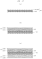
- FIG. 2 is a diagram showing a manufacturing process of a solid electrolyte membrane according to the present embodiment.
- a solid electrolyte membrane is formed using the ultrafine fiber non-woven fabric obtained by the above-described ⁇ Method of fabricating ultrafine fiber non-woven fabric>.
- the ultrafine fiber non-woven fabric UFN shown in FIG. 2 ( a ) and the slurry S containing the solid electrolyte material (solid electrolyte particles 4 AP) are prepared.
- the slurry S is obtained by dispersing a solid electrolyte material in a liquid (solvent, dispersion medium). If necessary, a binder or the like may be added.
- the slurry S containing the solid electrolyte material is applied onto the ultrafine fiber non-woven fabric UFN.
- FIG. 2 ( b ) the slurry S containing the solid electrolyte material is applied onto the ultrafine fiber non-woven fabric UFN.
- the solid electrolyte membrane 40 in which the solid electrolyte material (solid electrolyte particles 4 AP) is incorporated in the fine pores of the ultrafine fiber non-woven fabric UFN in which the ultrafine fibers UF are mutually entwined to be laminated ( FIG. 2 ( c ) ).
- the solid electrolyte membrane 40 can be formed by a simple process and at low cost.
- solid electrolyte material after the liquid component has been removed is denoted by “ 40 A”. Further, the process of removing the liquid component of the slurry S (drying process) and the process of pressurizing the solid electrolyte material (solid electrolyte particles 4 AP) may be separately performed.
- FIG. 3 is a cross-sectional view schematically showing a configuration of an all-solid-state battery according to a comparative example.
- FIG. 4 is a diagram showing a manufacturing process of a solid electrolyte sheet of the all-solid-state battery according to the comparative example.
- a solid electrolyte sheet (thickness: 37 to 138 ⁇ m) is fabricated by filling a solid electrolyte into a polyimide sheet-like support ( FIG. 4 ( a ) ) in which a plurality of through holes having a square shape with a side of 200 to 800 ⁇ m processed by a photoetching method is formed ( FIG. 4 ( b ) ), and then heating and pressurizing the support with a press machine ( FIG. 4 ( c ) ).
- each hole has a square shape with a side of 200 to 800 ⁇ m, and there is a limitation in the opening ratio. Namely, when the opening ratio is increased, the contact area between the solid electrolyte and the positive and negative electrodes can be increased, but there is a concern that the solid electrolyte material may fall off or collapse. Further, the thickness of the sheet (T 2 ) is as large as 37 to 138 ⁇ m. On the other hand, in the present embodiment, the film thickness (T) of the solid electrolyte membrane 40 can be easily adjusted, and the film thickness can be set to, for example, 20 ⁇ m or less.
- the characteristics (thickness, fiber diameter, pore diameter, etc.) of the ultrafine fiber non-woven fabric can be easily adjusted by adjusting the processing conditions (applied voltage, distance between the nozzle and the laser irradiation unit, processing time, etc.).
- the volume ratio of the non-woven fabric serving as the support to the solid electrolyte membrane can be suppressed, and can be set to, for example, 10 vol % or more and 30 vol % or less.
- the characteristics of the solid electrolyte membrane can be improved.
- a fiber web (also referred to as non-woven fabric, fiber bundle, or fiber sheet) of HDPE was fabricated by the laser electrospinning (LES) method.
- LES apparatus an electrospinning (ES) apparatus manufactured by Kato Tech Co., Ltd. and a carbon dioxide laser generator (PIN- 30 R) manufactured by Onizuka Glass Co., Ltd were used in combination.
- ES electrospinning
- PIN- 30 R carbon dioxide laser generator
- the LES apparatus was covered with an enclosure box made of acrylic resin, and the atmosphere inside the enclosure box was maintained at a humidity of 10 to 30% RH by supplying dry air. In this way, it was possible to eliminate the influence of humidity during fiber formation.
- the wavelength of the CO 2 laser beam was 10.6 ⁇ m, and the laser beam horizontally emitted from the apparatus was reflected by a mirror and the raw material resin directly below the mirror was irradiated with the laser beam.
- the cross-section of the laser beam at the time of emission was circular with a fiber diameter of 6 mm, and it was converted by a beam shape conversion element (expander) so as to have 2.1 mm in a fiber axis direction and 13 mm in a direction horizontal to the fiber axis at the irradiation portion.
- the irradiation diameter of the laser beam was set to about 1.1 mm in the fiber axis direction and about 8.0 mm in the vertical direction by using a slit.
- the diameter of the raw material resin (fibrous) was about 0.5 mm, the distance between the nozzle and the collector was 80 mm, the distance from the nozzle to the central axis of the laser beam was 0.7 mm, and the sending speed was 40 mm/min.
- a roller no rotation, traverse speed: 2 mm/sec was used as a fiber collector (collection plate), and the fiber web of HDPE was fabricated by changing the laser output to 11 to 16 W and changing the applied voltage to 11 to 24 kV.
- FIG. 6 is a diagram (photograph) showing a state of a nozzle tip at the time of forming the fiber web of HDPE.
- FIG. 7 is a SEM photograph of the fiber web of HDPE. Morphological observation was performed using SEM (KYENCE, VE-7800). Prior to the observation, gold evaporation was performed by ion sputter (E-1010 manufactured by Hitachi, Ltd.) so as to enable the SEM observation. In the observation, the distance between two points in the fiber diameter direction was defined as one point for each fiber in the obtained SEM image, and the fiber diameter was obtained by measuring a total of 100 points by using the image analysis software ImageJ. The fiber diameter was a dozen ⁇ m or more.
- a fiber web of CeNF-added HDPE was fabricated by the laser electrospinning (LES) method.
- HDPE added with CeNF was used as a raw material resin, and the fiber web was fabricated in the same manner as in Example 1.
- the amount of CeNF added to HDPE was 1 vol % (CeNF: 1 vol %, HDPE: 99 vol %), and CEOLUS FD101 (manufactured by Asahi Kasei Chemicals Co., Ltd.) was used as CeNF.
- FIG. 8 is a diagram (photograph) showing a state of a nozzle tip at the time of forming the fiber web of CeNF-added HDPE.
- FIG. 9 is a SEM photograph of the fiber web of CeNF-added HDPE. The fiber diameter of the fiber web of CeNF-added HDPE was 5 ⁇ m or less (about 4 ⁇ m).
- Example 2 As compared with the case of Example 1 in which CeNF was not added, the fiber could be smoothly stretched, the fiber spinning was stable, the fiber diameter was reduced, and the fiber web with uniform thickness was obtained.
- FIG. 10 is a cross-sectional view showing a manufacturing process of an all-solid-state battery.
- the solid electrolyte membrane 40 in which the solid electrolyte particles 4 AP are incorporated between the ultrafine fibers UF ( FIG. 10 ( a ) ) is formed based on the above-mentioned [Method of fabricating solid electrolyte membrane].
- the positive electrode active material 3 AP and the solid electrolyte material is mounted on the upper surface side (positive electrode side) of the solid electrolyte membrane 40 , the positive electrode current collector 30 B is mounted thereon, and then, they are pressurized (pressed). In this way, the positive electrode (positive electrode mixture layer 30 A and positive electrode current collector 30 B) is formed on the upper surface of the solid electrolyte membrane 40 ( FIG. 10 ( b ) ).
- the negative electrode current collector 20 B is mounted thereon, and then, they are pressurized (pressed). In this way, the negative electrode (negative electrode mixture layer 20 A and negative electrode current collector 20 B) is formed on the lower surface side (negative electrode side) of the solid electrolyte membrane 40 ( FIG. 10 ( c ) ).
- an electrode group composed of the positive electrode current collector 30 B, the positive electrode mixture layer 30 A, the solid electrolyte membrane 40 , the negative electrode mixture layer 20 A, and the negative electrode current collector 20 B is formed.
- the all-solid-state battery can be formed by inserting the electrode group into the battery case and sealing the battery case.
- the pressurizing process may be performed at once after the positive electrode active material 3 AP and the like, the solid electrolyte membrane 40 , the negative electrode active material 2 AP and the like, and the negative electrode current collector 20 B are sequentially stacked on the positive electrode current collector 30 B.
- lithium ions are desorbed from the positive electrode active material 3 AP of the positive electrode mixture layer 30 A during the charging process, and lithium ions desorbed from the negative electrode active material 2 AP of the negative electrode mixture layer 20 A are inserted during the discharging process. In this way, charging and discharging can be performed by inserting and desorbing lithium ions.
- the solid electrolyte membrane 40 in which the solid electrolyte material (particles) is incorporated in the ultrafine fiber non-woven fabric UFN used as a support, it is possible to manufacture an all-solid-state battery having favorable characteristics. Specifically, as described above, by supporting (fixing) the solid electrolyte material, which is fine particles, with the ultrafine fiber UF, the ratio of the solid electrolyte material in the solid electrolyte membrane 40 can be increased, and the occupied area (exposed area) of the solid electrolyte material on the surface of the membrane can be increased.
- the contact area between the solid electrolyte membrane 40 and the positive and negative electrodes (positive and negative electrode active materials) can be improved, and the characteristics (output characteristics, charge/discharge characteristics) of the all-solid-state battery can be improved.
- the film thickness of the solid electrolyte membrane 40 can be reduced and the resistance between the positive electrode and the negative electrode can be reduced, so that the characteristics (output characteristics, charge/discharge characteristics) of the all-solid-state battery can be improved.
- FIG. 11 is a schematic diagram showing a configuration of a manufacturing apparatus (system) according to the present embodiment.
- FIG. 12 is a diagram showing a configuration of a twin-screw kneading extruder
- FIG. 13 is a diagram showing a configuration of a part of the extruder
- FIG. 14 is a diagram showing a configuration of a screw.
- FIG. 15 is a diagram showing a configuration of a non-woven fabric manufacturing machine
- FIG. 16 is a diagram showing a configuration of an all-solid-state battery laminate manufacturing machine.
- S 1 indicates a processing section by a twin-screw kneading extruder
- S 2 indicates a processing section by a non-woven fabric manufacturing machine
- S 3 indicates a processing section by an all-solid-state battery laminate manufacturing machine.
- the twin-screw kneading extruder EM is an apparatus that melts and kneads the input raw material with two shafts having screws that mesh with each other (see FIG. 12 to FIG. 14 ) and extrudes it.
- CeNF is kneaded with the molten resin.
- a thermoplastic resin for example, a thermoplastic resin can be used.
- polyethylene polyvinylidene fluoride (PVDF), polymethylpentene, polyethylene terephthalate (PET), polybutylene terephthalate (PBT), and the like can be used. These resins may be used alone or as a mixture of a plurality of these resins.
- the polymer constituting the resin those having a molecular weight of 1000 or more and 100,000 or less can be used.
- HDPE high-density polyethylene
- the fiber diameter of the ultrafine fiber constituting the ultrafine fiber non-woven fabric is, for example, about 5 to 35 ⁇ m.
- CeNF can be added as a CeNF dispersion liquid.
- the CeNF the one described in the first embodiment can be used.
- the CeNF subjected to surface treatment may also be used. By performing the surface treatment in this way, the defibration properties of CeNF are improved and the affinity with the resin is also improved.
- the dispersion medium a material which is liquid at room temperature, for example, water, an organic solvent such as ethanol or toluene, and oil such as liquid paraffin or process oil is preferable.
- These dispersion media may be used alone or as a mixture of a plurality of these media.
- the concentration of the filler dispersion liquid is preferably 5 to 80 wt %, more preferably 10 to 60 wt %.
- thermoplastic resin and the filler dispersion liquid As the kneading apparatus for the thermoplastic resin and the filler dispersion liquid, a single-screw extruder, a twin-screw extruder, a multi-screw extruder, or the like can be used. By using such an extruder, the materials can be continuously and rapidly mixed to uniformly disperse CeNF.
- the injection location of the CeNF dispersion liquid is preferably on the downstream side of the plasticizing region of the resin, and the CeNF dispersion liquid is injected in the state where the molten resin is filled on the upstream side of the injection point.
- the injection device for example, the injection nozzle
- the injection device may be provided at one place, but may be provided at a plurality of places in order to improve the dispersion.
- the amount of the filler added to the resin is preferably 0.1 vol % to 40 vol %, more preferably 0.1 vol % to 10 vol %, still more preferably 1 vol % to 10 vol %.
- the addition ratio is shown by vol % here.
- the extruder EM includes a cylinder 11 whose temperature is controlled by temperature control means (not shown), a screw ( 12 ) arranged in the cylinder 11 so as to be rotatable (freely rotatable) by a rotation drive mechanism 15 , a hopper (input port) 13 provided on the upstream side of the cylinder 11 , and a die 14 provided on the downstream end of the cylinder 11 , and has a plasticization zone (plasticization part) A, a kneading zone (kneading part) B, and a devolatilization zone (deaeration part) C provided sequentially from the side of the hopper 13 to the side of the die 14 .
- a plasticization zone plasticization part
- kneading zone kneading part
- devolatilization zone devolatilization zone
- an injection nozzle 160 for injecting the filler dispersion liquid is provided in a portion of the cylinder 11 corresponding to the kneading zone B, and a forced exhaust port 111 connected to a vacuum pump (deaeration device) 112 is provided in a portion of the cylinder 11 corresponding to the devolatilization zone C.
- a plunger pump (liquid addition pump) 17 is connected to the injection nozzle 160 .
- FIG. 13 As shown in FIG. 13 , two screws (a plurality of screws mounted on shafts) are rotatably inserted and incorporated in the cylinder 11 .
- the two screws are arranged and rotated so as to mesh with each other.
- the screw has a plurality of screw pieces.
- FIG. 14 is a perspective view showing an example of a shape of the screw (screw piece).
- FIG. 14 ( a ) is a full flight screw and
- FIG. 14 ( b ) is a kneading disc.
- the configuration shown in FIG. 13 is an example, and the combination of screw pieces can be changed as appropriate.
- thermoplastic resin supplied from the hopper 13 is melted in the plasticization zone A in the extruder EM and transferred to the kneading zone B. Then, after the filler dispersion liquid is injected into the molten resin from the injection nozzle 160 , the molten resin and the filler dispersion liquid are mixed and kneaded, and then transferred to the devolatilization zone C. In the devolatilization zone C, the gasified dispersion medium is removed (exhausted) from the forced exhaust port 111 , and the resin is extruded as a strand from the die 14 .
- FIG. 15 is a schematic diagram showing the configuration of a laser electrospinning apparatus.
- the laser electrospinning apparatus includes the nozzle 3 that sends out the raw material resin, the laser irradiation unit 8 that irradiates the tip of the nozzle 3 with the laser (CO 2 laser) 10 , and the collector (fiber collecting unit) 6 that stretches the fibers discharged from the nozzle 3 by electrostatic force.
- a high voltage is applied between the collector 6 and the nozzle 3 by the high voltage generation source 5 , and the collector 6 is connected to the ground potential 7 .
- the laser irradiation unit 8 irradiates the tip of the nozzle 3 with the laser 10 through the slit 9 .
- the thread-like resin (raw material resin) 1 as a raw material is supplied to the nozzle 3 through the roller 2 .
- the raw material resin 1 extruded from the nozzle 3 is irradiated with the laser 10 in the state of applying a high voltage between the nozzle 3 and the collector 6 by the high voltage generation source 5 , the raw material resin 1 is instantaneously and uniformly heated and melted, stretched by electrostatic force to become the ultrafine fiber UF, and collected on the collector 6 .
- the non-woven fabric (fiber web) UFN can be obtained by laminating the ultrafine fibers UF while being entwined with each other.
- the ultrafine fiber to be formed becomes finer and more uniform. It is conceivable that this is because the hydroxyl group (—OH) of cellulose is a polar group, so that the fiber is easily attracted by the electrostatic force of the collector 6 and becomes finer and more uniform, that is, the stretching effect is increased.
- the fiber diameter of the ultrafine fiber obtained by the LES method can be made finer and more uniform. Further, the pore diameter of the ultrafine fiber non-woven fabric obtained by the LES method can be made finer and more uniform.
- FIG. 16 is a schematic diagram showing a configuration of an all-solid-state battery laminate manufacturing machine.
- the all-solid-state battery laminate manufacturing machine includes rollers R 1 and R 2 that convey the non-woven fabric (fiber web) UFN manufactured by the laser electrospinning apparatus, nozzles N 1 and N 2 that apply the slurry onto the non-woven fabric (fiber web) UFN, and heaters H 1 and H 2 for drying the applied film (coated film).
- it further includes a press PR 1 (rollers R 3 and R 4 ) that pressurizes the applied film, a feeder W 1 that sends out the positive electrode member onto one surface of the applied film, a feeder W 2 that sends out the negative electrode member onto the other surface of the applied film, a press PR 2 that pressurizes a laminated body of the applied film, the positive electrode member EL 1 , and the negative electrode member EL 2 , and a winding machine W that winds the laminated body after pressurization.
- a press PR 1 rollerers R 3 and R 4
- a feeder W 1 that sends out the positive electrode member onto one surface of the applied film
- a feeder W 2 that sends out the negative electrode member onto the other surface of the applied film
- a press PR 2 that pressurizes a laminated body of the applied film, the positive electrode member EL 1 , and the negative electrode member EL 2
- a winding machine W that winds the laminated body after pressurization.
- the slurry containing the solid electrolyte material (solid electrolyte particles 4 AP) is discharged from the nozzle N 1 onto the surface of the non-woven fabric (fiber web) UFN.
- the slurry is discharged onto the non-woven fabric (fiber web) UFN from the slit-shaped nozzle hole.
- the discharged slurry is heated (dried) by the heater H 1 to become an applied film.
- the slurry containing the solid electrolyte material (solid electrolyte particles 4 AP) is discharged from the nozzle N 2 onto the back surface of the non-woven fabric (fiber web) UFN.
- the slurry is discharged from the slit-shaped nozzle hole to the back surface of the non-woven fabric (fiber web) UFN.
- the discharged slurry is heated (dried) by the heater H 2 to become an applied film.
- the applied films on both surfaces of the non-woven fabric (fiber web) UFN are pressurized by the press PR 1 composed of the rollers R 3 and R 4 .
- the liquid component of the slurry is vaporized and the solid electrolyte material (solid electrolyte particles 4 AP) is embedded (filled) in the fine pores of the ultrafine fiber non-woven fabric UFN, so that the solid electrolyte membrane 40 in which the solid electrolyte material (solid electrolyte particles 4 AP) is incorporated in the fine pores of the ultrafine fiber non-woven fabric UFN in which the ultrafine fibers UF are entwined to be laminated can be formed (see also FIG. 2 ( c ) ).
- the positive electrode member EL 1 is laminated on the surface of the solid electrolyte membrane 40 from the feeder W 1
- the negative electrode member EL 2 is laminated on the back surface of the solid electrolyte membrane 40 from the feeder W 2 .
- the positive electrode member EL 1 is composed of, for example, the positive electrode 30 having the positive electrode mixture layer 30 A and the positive electrode current collector 30 B
- the negative electrode member EL 2 is composed of, for example, the negative electrode 20 having the negative electrode mixture layer 20 A and the negative electrode current collector 20 B.
- the feeders W 1 and W 2 send out each member such that the mixture layers are in contact with the solid electrolyte membrane 40 .
- the mixture layer contains an active material and a solid electrolyte material, which enables the conduction of Li ions.
- the laminated body of the positive electrode member ELI, the solid electrolyte membrane 40 , and the negative electrode member EL 2 is pressurized by the press PR 2 , and the pressurized laminated body is wound around the winding machine W.
- the solid electrolyte membrane 40 and the laminated body of the positive electrode member EL 1 , the solid electrolyte membrane 40 , and the negative electrode member EL 2 can be efficiently manufactured.
- the slurry containing the solid electrolyte material is applied to one surface of the ultrafine fiber non-woven fabric UFN, but the slurry containing the solid electrolyte material may be applied to both surfaces of the ultrafine fiber non-woven fabric UFN. Further, in the second embodiment ( FIG. 17 ), the slurry containing the solid electrolyte material may be applied to one surface of the ultrafine fiber non-woven fabric UFN by omitting the nozzle N 2 and the heater H 2 .
- the positive electrode member and the negative electrode member are laminated with the solid electrolyte membrane 40 by a feeder.
- the laminated body of the positive electrode member EL 1 , the solid electrolyte membrane 40 , and the negative electrode member EL 2 may be formed by forming the mixture layer by applying and drying the slurry containing the active material and the solid electrolyte material on the solid electrolyte membrane 40 , and further laminating the current collector on the mixture layer.
- the nozzle is used to apply the slurry containing the solid electrolyte material onto the ultrafine fiber non-woven fabric UFN, but a gravure coating machine may be used to apply the slurry.
- a gravure coating machine may be used for applying the slurry containing the active material and the solid electrolyte material of the above application example 2.
- the non-woven fabric (UFN) is formed of the resin to which cellulose nanofiber (CeNF) is added, but the addition of the cellulose nanofiber (CeNF) maybe omitted.
- the manufacturing apparatus ( FIG. 11 ) described in the second embodiment can be used for manufacturing an all-solid-state battery using a non-woven fabric (UFN) to which cellulose nanofiber (CeNF) is not added.
- the manufacturing apparatus described in the second embodiment can be used for manufacturing an all-solid-state battery using a non-woven fabric (UFN) to which a filler other than cellulose nanofiber (CeNF) is added.
- filler for example, natural materials such as ramie, jute, kenaf, bamboo, and bagasse, carbon materials such as carbon fiber, carbon nanofiber, carbon nanotube, fullerene, and carbon black, and mineral materials such as glass, calcium carbonate, titanium dioxide, and talc can be used in addition to cellulose containing CeNF.
- a filler subjected to surface treatment may also be used.
- the process by the twin-screw kneading extruder (S 1 ), the process by the non-woven fabric manufacturing machine (S 2 ), and the process by the all-solid-state battery laminate manufacturing machine (S 3 ) do not have to be continuously performed.
- the strand may be cooled by a strand bath and sequentially cut into pellets by a strand cutter (cutting device). Then, after the pellets are melted to form strands having a desired diameter, the strand may be processed by the non-woven fabric manufacturing machine (S 2 ).
- the wound strand (raw material resin) having the desired diameter may be processed by the non-woven fabric manufacturing machine (S 2 ).
- the non-woven fabric (UFN) formed by the non-woven fabric manufacturing machine (S 2 ) may be wound up by the winding machine WU. Then, as shown in FIG. 17 , the laminated body of the positive electrode member EL 1 , the solid electrolyte membrane 40 , and the negative electrode member EL 2 may be formed by sending out the wound non-woven fabric (UFN) as described in the second embodiment.
- FIG. 17 is a diagram showing a configuration of an all-solid-state battery laminate manufacturing machine according to the application example 5.
- the laminated body of the positive electrode member EL 1 , the solid electrolyte membrane 40 , and the negative electrode member EL 2 may be formed by using a non-woven fabric (UFN) formed and wound by a method other than the laser electrospinning (LES) method ( FIG. 17 ).
- UFN non-woven fabric
- LES laser electrospinning
- FIG. 18 is a diagram showing a configuration of an all-solid-state battery laminate manufacturing machine according to the application example 6. For example, after applying the slurry onto the front surface of the non-woven fabric (UFN) by the nozzle Nia and applying the slurry onto the back surface of the non-woven fabric (UFN) by the nozzle Nib, the slurry is heated by the heater H 1 and is pressurized by the rollers R 3 and R 4 .
- FIG. 19 is a diagram showing a configuration of an all-solid-state battery laminate manufacturing machine according to the application example 7. For example, after applying the slurry onto the front surface of the non-woven fabric (UFN) by the nozzle Nia and applying the slurry onto the back surface of the non-woven fabric (UFN) by the nozzle Nib, the slurry is heated by the heater H 1 and is pressurized by the rollers R 3 and R 4 .
- FIG. 20 is a diagram showing a configuration of an all-solid-state battery laminate manufacturing machine according to the application example 8 .
- the different solid electrolyte membranes sent from the feeders W 1 and W 2 of the above application example 7 may be formed by the application of the slurry from nozzles N 2 a and N 2 b and the heat treatment by the heaters H 3 and H 4 .
- a secondary battery has been described as an example of a lithium battery, but the present invention can be applied also to a primary battery.
- a lithium battery has been described as an example, but the present invention can be applied also to other all-solid-state batteries.
- CeNF having hydroxyl group (—OH) has been described as an example of a polar filler, but other fillers having a polar group may be used. Both an organic filler and an inorganic filler may be used as the filler.
Landscapes
- Engineering & Computer Science (AREA)
- Chemical & Material Sciences (AREA)
- Manufacturing & Machinery (AREA)
- General Chemical & Material Sciences (AREA)
- Electrochemistry (AREA)
- Chemical Kinetics & Catalysis (AREA)
- Mechanical Engineering (AREA)
- Textile Engineering (AREA)
- Inorganic Chemistry (AREA)
- General Physics & Mathematics (AREA)
- Condensed Matter Physics & Semiconductors (AREA)
- Physics & Mathematics (AREA)
- Dispersion Chemistry (AREA)
- Materials Engineering (AREA)
- Secondary Cells (AREA)
- Primary Cells (AREA)
- Battery Electrode And Active Subsutance (AREA)
- Cell Separators (AREA)
Abstract
Description
-
- 1 raw material resin
- 2 roller
- 2AP negative electrode active material
- 3 nozzle
- 3AP positive electrode active material
- 4AP solid electrolyte particle
- 5 high voltage generation source
- 6 collector
- 7 ground potential
- 8 laser irradiation unit
- 9 slit
- 10 laser
- 11 cylinder
- 12 screw
- 13 hopper
- 14 die
- 15 rotation drive mechanism
- 17 plunger pump (liquid addition pump)
- 20 negative electrode
- 20A negative electrode mixture layer
- 20B negative electrode current collector
- 30 positive electrode
- 30A positive electrode mixture layer
- 30B positive electrode current collector
- 40 solid electrolyte membrane
- 111 forced exhaust port
- 112 vacuum pump (deaeration device)
- 160 injection nozzle
- A plasticization zone (plasticization part)
- B kneading zone (kneading part)
- C devolatilization zone (deaeration part)
- EL1 positive electrode member
- EL2 negative electrode member
- EM twin-screw kneading extruder (extruder)
- H1 heater
- H2 heater
- H3 heater
- H4 heater
- N1 nozzle
- N1 a nozzle
- N1 b nozzle
- N2 nozzle
- N2 a nozzle
- N2 b nozzle
- PR1 press
- PR2 press
- R1 roller
- R2 roller
- R3 roller
- R4 roller
- R5 roller
- R6 roller
- S slurry
- S1 process by twin-screw kneading extruder
- S2 process by non-woven fabric manufacturing machine
- S3 process by all-solid-state battery laminate manufacturing machine
- UF ultrafine fiber
- UFN ultrafine fiber non-woven fabric (non-woven fabric)
- W winding machine
- W1 feeder
- W2 feeder
- WU winding machine
Claims (7)
Applications Claiming Priority (3)
| Application Number | Priority Date | Filing Date | Title |
|---|---|---|---|
| JP2019085279A JP7390635B2 (en) | 2019-04-26 | 2019-04-26 | Solid electrolyte membrane manufacturing method, all-solid-state battery manufacturing method, solid-state electrolyte membrane manufacturing device, and all-solid-state battery manufacturing device |
| JP2019-085279 | 2019-04-26 | ||
| PCT/JP2020/017501 WO2020218422A1 (en) | 2019-04-26 | 2020-04-23 | Method for producing solid electrolyte membrane, method for producing all-solid-state battery, apparatus for producing solid electrolyte membrane, and apparatus for producing all-solid-state battery |
Related Parent Applications (1)
| Application Number | Title | Priority Date | Filing Date |
|---|---|---|---|
| PCT/JP2020/017501 A-371-Of-International WO2020218422A1 (en) | 2019-04-26 | 2020-04-23 | Method for producing solid electrolyte membrane, method for producing all-solid-state battery, apparatus for producing solid electrolyte membrane, and apparatus for producing all-solid-state battery |
Related Child Applications (1)
| Application Number | Title | Priority Date | Filing Date |
|---|---|---|---|
| US18/792,996 Division US20240396092A1 (en) | 2019-04-26 | 2024-08-02 | Method of manufacturing solid electrolyte membrane, method of manufacturing all-solid-state battery, apparatus for manufacturing solid electrolyte membrane, and apparatus for manufacturing all-solid-state battery |
Publications (2)
| Publication Number | Publication Date |
|---|---|
| US20220181703A1 US20220181703A1 (en) | 2022-06-09 |
| US12087911B2 true US12087911B2 (en) | 2024-09-10 |
Family
ID=72942792
Family Applications (2)
| Application Number | Title | Priority Date | Filing Date |
|---|---|---|---|
| US17/594,650 Active 2040-12-26 US12087911B2 (en) | 2019-04-26 | 2020-04-23 | Method of manufacturing a solid electrolyte membrane |
| US18/792,996 Pending US20240396092A1 (en) | 2019-04-26 | 2024-08-02 | Method of manufacturing solid electrolyte membrane, method of manufacturing all-solid-state battery, apparatus for manufacturing solid electrolyte membrane, and apparatus for manufacturing all-solid-state battery |
Family Applications After (1)
| Application Number | Title | Priority Date | Filing Date |
|---|---|---|---|
| US18/792,996 Pending US20240396092A1 (en) | 2019-04-26 | 2024-08-02 | Method of manufacturing solid electrolyte membrane, method of manufacturing all-solid-state battery, apparatus for manufacturing solid electrolyte membrane, and apparatus for manufacturing all-solid-state battery |
Country Status (7)
| Country | Link |
|---|---|
| US (2) | US12087911B2 (en) |
| EP (1) | EP3961776A4 (en) |
| JP (1) | JP7390635B2 (en) |
| KR (1) | KR102861903B1 (en) |
| CN (1) | CN114207887B (en) |
| TW (1) | TWI878288B (en) |
| WO (1) | WO2020218422A1 (en) |
Families Citing this family (11)
| Publication number | Priority date | Publication date | Assignee | Title |
|---|---|---|---|---|
| US11807957B2 (en) * | 2020-05-22 | 2023-11-07 | University Of Dayton Research Institute | Creating defined electrospun fiber geometries |
| WO2022168409A1 (en) * | 2021-02-08 | 2022-08-11 | パナソニックIpマネジメント株式会社 | Battery and method for producing same |
| CN113675480A (en) * | 2021-07-19 | 2021-11-19 | 华南理工大学 | Lithium ion battery cell with sandwich structure, electric pile and preparation method thereof |
| JP7155360B1 (en) * | 2021-08-02 | 2022-10-18 | 株式会社日本製鋼所 | Reactor, reaction system, material manufacturing system, battery material manufacturing system, battery manufacturing system, reaction product manufacturing method, battery material manufacturing method, and battery manufacturing method |
| JP7524874B2 (en) | 2021-09-27 | 2024-07-30 | トヨタ自動車株式会社 | All-solid-state battery |
| JP7524873B2 (en) | 2021-09-27 | 2024-07-30 | トヨタ自動車株式会社 | All-solid-state battery |
| JP7524872B2 (en) | 2021-09-27 | 2024-07-30 | トヨタ自動車株式会社 | All-solid-state battery |
| US12492506B2 (en) * | 2023-06-13 | 2025-12-09 | The Boeing Company | Fabricating methods and apparatuses for a multilayered, nanoparticle-coated fiber material |
| CN117059914B (en) * | 2023-07-12 | 2024-06-14 | 苏州大学 | High-low temperature resistant integrated zinc ion fiber battery and preparation method thereof |
| KR20250081514A (en) * | 2023-11-29 | 2025-06-05 | 삼성에스디아이 주식회사 | All solid-state battery |
| WO2025144916A1 (en) * | 2023-12-29 | 2025-07-03 | Saint-Gobain Ceramics & Plastics, Inc. | Structure including solid electrolyte material and organic material and methods of forming |
Citations (25)
| Publication number | Priority date | Publication date | Assignee | Title |
|---|---|---|---|---|
| JPH07335218A (en) | 1994-06-07 | 1995-12-22 | Fuji Elelctrochem Co Ltd | Non-aqueous electrolyte secondary battery |
| JPH07335216A (en) | 1994-06-07 | 1995-12-22 | Fuji Elelctrochem Co Ltd | Non-aqueous electrolyte secondary battery |
| JPH07335217A (en) | 1994-06-07 | 1995-12-22 | Fuji Elelctrochem Co Ltd | Non-aqueous electrolyte secondary battery |
| US6288144B1 (en) * | 1999-04-20 | 2001-09-11 | Uniroyal Chemical Company, Inc. | Processing of coupled, filled polyolefins |
| JP2007262644A (en) | 2006-02-28 | 2007-10-11 | Shinshu Univ | Ultrafine fiber and its manufacturing method |
| JP2009299212A (en) | 2008-06-11 | 2009-12-24 | Univ Of Fukui | Spinning method, and method and apparatus for producing fiber using the same |
| JP2010250982A (en) | 2009-04-10 | 2010-11-04 | Idemitsu Kosan Co Ltd | Solid electrolyte sheet and lithium secondary battery |
| US20110275520A1 (en) | 2008-10-01 | 2011-11-10 | Frey Margaret W | Biodegradable chemical delivery system |
| US20130085212A1 (en) | 2010-05-04 | 2013-04-04 | Consejo Superior De Investigaciones Cientificas (Csic) | Procedure for the obtainment of nanocomposite materials |
| JP2013127982A (en) | 2013-02-22 | 2013-06-27 | Idemitsu Kosan Co Ltd | Solid electrolyte sheet for lithium battery, manufacturing method for the same, and all-solid secondary battery using the same |
| US20140121307A1 (en) * | 2012-10-30 | 2014-05-01 | Cyclewood Solutions, Inc. | Blending lignin with thermoplastics and a coupling agent or compatibilizer |
| JP2014143006A (en) | 2013-01-22 | 2014-08-07 | Daicel Corp | Composite sheet containing cellulose and solid electrolyte film |
| JP2017103146A (en) | 2015-12-03 | 2017-06-08 | 地方独立行政法人大阪府立産業技術総合研究所 | Solid electrolyte sheet and manufacturing method thereof, and all-solid battery and manufacturing method thereof |
| JP2017183111A (en) | 2016-03-30 | 2017-10-05 | 旭化成株式会社 | Separator and method of manufacturing the same |
| US20170298535A1 (en) * | 2014-10-20 | 2017-10-19 | Daicel Corporation | High melting point resin fibers and nonwoven fabric |
| JP2018101641A (en) | 2018-03-19 | 2018-06-28 | 古河機械金属株式会社 | Solid electrolyte sheet, all solid-state lithium ion battery, and method for producing solid electrolyte sheet |
| WO2018212568A1 (en) | 2017-05-15 | 2018-11-22 | 주식회사 엘지화학 | Method for manufacturing solid electrolyte membrane for solid-state battery and solid electrolyte membrane manufactured by same method |
| CN108884595A (en) | 2016-04-11 | 2018-11-23 | 花王株式会社 | Method for producing ultrafine fibers |
| US20180375148A1 (en) | 2017-06-23 | 2018-12-27 | GM Global Technology Operations LLC | Ionically-conductive reinforced glass ceramic separators/solid electrolytes |
| JP2018204140A (en) | 2017-06-02 | 2018-12-27 | 国立大学法人京都工芸繊維大学 | Manufacturing method of fiber sheet |
| CN109244327A (en) | 2018-09-25 | 2019-01-18 | 合肥先杰新能源科技有限公司 | The preparation method of lithium ion battery composite separation membrane |
| WO2019065066A1 (en) | 2017-09-28 | 2019-04-04 | 富士フイルム株式会社 | Solid electrolyte composition, solid electrolyte-containing sheet, all-solid-state secondary battery, method for producing solid electrolyte-containing sheet, and method for producing all-solid-state secondary battery |
| US20190237731A1 (en) | 2018-02-01 | 2019-08-01 | Samsung Electronics Co., Ltd. | Porous film, separator including porous film, electrochemical device including porous film, and method of preparing porous film |
| US20190288332A1 (en) | 2018-03-16 | 2019-09-19 | Kabushiki Kaisha Toshiba | Secondary battery, battery pack, vehicle, and stationary power supply |
| WO2019208347A1 (en) | 2018-04-27 | 2019-10-31 | 富士フイルム株式会社 | Solid electrolyte-including sheet, electrode sheet for fully solid-state secondary battery, fully solid-state secondary battery, electronic device, electric vehicle, and manufacturing methods for these |
Family Cites Families (5)
| Publication number | Priority date | Publication date | Assignee | Title |
|---|---|---|---|---|
| JP5462227B2 (en) * | 2011-09-07 | 2014-04-02 | 株式会社日本製鋼所 | Process for producing polyolefin microporous stretched film with cellulose nanofiber, polyolefin microporous stretched film with cellulose nanofiber, and separator for non-aqueous secondary battery |
| JP2015161051A (en) * | 2014-02-28 | 2015-09-07 | 東レ株式会社 | Method for manufacturing nanofiber and nanofiber |
| JP6647113B2 (en) * | 2016-03-31 | 2020-02-14 | 日立造船株式会社 | Manufacturing method of all solid state secondary battery |
| KR101804222B1 (en) | 2016-03-03 | 2018-01-10 | (주)태림기연 | Automatic remote control device capable of compressing the waste plastic bottles |
| CN109494390A (en) * | 2018-10-30 | 2019-03-19 | 溧阳天目先导电池材料科技有限公司 | A kind of modified solid electrolyte membrane and preparation method thereof and lithium battery |
-
2019
- 2019-04-26 JP JP2019085279A patent/JP7390635B2/en active Active
-
2020
- 2020-04-23 KR KR1020217036943A patent/KR102861903B1/en active Active
- 2020-04-23 TW TW109113635A patent/TWI878288B/en active
- 2020-04-23 US US17/594,650 patent/US12087911B2/en active Active
- 2020-04-23 CN CN202080030604.4A patent/CN114207887B/en active Active
- 2020-04-23 EP EP20794341.6A patent/EP3961776A4/en active Pending
- 2020-04-23 WO PCT/JP2020/017501 patent/WO2020218422A1/en not_active Ceased
-
2024
- 2024-08-02 US US18/792,996 patent/US20240396092A1/en active Pending
Patent Citations (28)
| Publication number | Priority date | Publication date | Assignee | Title |
|---|---|---|---|---|
| JPH07335218A (en) | 1994-06-07 | 1995-12-22 | Fuji Elelctrochem Co Ltd | Non-aqueous electrolyte secondary battery |
| JPH07335216A (en) | 1994-06-07 | 1995-12-22 | Fuji Elelctrochem Co Ltd | Non-aqueous electrolyte secondary battery |
| JPH07335217A (en) | 1994-06-07 | 1995-12-22 | Fuji Elelctrochem Co Ltd | Non-aqueous electrolyte secondary battery |
| US6288144B1 (en) * | 1999-04-20 | 2001-09-11 | Uniroyal Chemical Company, Inc. | Processing of coupled, filled polyolefins |
| JP2007262644A (en) | 2006-02-28 | 2007-10-11 | Shinshu Univ | Ultrafine fiber and its manufacturing method |
| JP2009299212A (en) | 2008-06-11 | 2009-12-24 | Univ Of Fukui | Spinning method, and method and apparatus for producing fiber using the same |
| US20110275520A1 (en) | 2008-10-01 | 2011-11-10 | Frey Margaret W | Biodegradable chemical delivery system |
| JP2010250982A (en) | 2009-04-10 | 2010-11-04 | Idemitsu Kosan Co Ltd | Solid electrolyte sheet and lithium secondary battery |
| US20130085212A1 (en) | 2010-05-04 | 2013-04-04 | Consejo Superior De Investigaciones Cientificas (Csic) | Procedure for the obtainment of nanocomposite materials |
| US20140121307A1 (en) * | 2012-10-30 | 2014-05-01 | Cyclewood Solutions, Inc. | Blending lignin with thermoplastics and a coupling agent or compatibilizer |
| JP2014143006A (en) | 2013-01-22 | 2014-08-07 | Daicel Corp | Composite sheet containing cellulose and solid electrolyte film |
| JP2013127982A (en) | 2013-02-22 | 2013-06-27 | Idemitsu Kosan Co Ltd | Solid electrolyte sheet for lithium battery, manufacturing method for the same, and all-solid secondary battery using the same |
| US20170298535A1 (en) * | 2014-10-20 | 2017-10-19 | Daicel Corporation | High melting point resin fibers and nonwoven fabric |
| JP2017103146A (en) | 2015-12-03 | 2017-06-08 | 地方独立行政法人大阪府立産業技術総合研究所 | Solid electrolyte sheet and manufacturing method thereof, and all-solid battery and manufacturing method thereof |
| JP2017183111A (en) | 2016-03-30 | 2017-10-05 | 旭化成株式会社 | Separator and method of manufacturing the same |
| CN108884595A (en) | 2016-04-11 | 2018-11-23 | 花王株式会社 | Method for producing ultrafine fibers |
| US20190372149A1 (en) | 2017-05-15 | 2019-12-05 | Lg Chem, Ltd. | Method for manufacturing solid electrolyte membrane for all solid type battery and solid electrolyte membrane manufactured by the method |
| WO2018212568A1 (en) | 2017-05-15 | 2018-11-22 | 주식회사 엘지화학 | Method for manufacturing solid electrolyte membrane for solid-state battery and solid electrolyte membrane manufactured by same method |
| JP2018204140A (en) | 2017-06-02 | 2018-12-27 | 国立大学法人京都工芸繊維大学 | Manufacturing method of fiber sheet |
| US20180375148A1 (en) | 2017-06-23 | 2018-12-27 | GM Global Technology Operations LLC | Ionically-conductive reinforced glass ceramic separators/solid electrolytes |
| CN109119683A (en) | 2017-06-23 | 2019-01-01 | 通用汽车环球科技运作有限责任公司 | Ionic conduction reinforcing glass ceramic diaphragm/solid electrolyte |
| WO2019065066A1 (en) | 2017-09-28 | 2019-04-04 | 富士フイルム株式会社 | Solid electrolyte composition, solid electrolyte-containing sheet, all-solid-state secondary battery, method for producing solid electrolyte-containing sheet, and method for producing all-solid-state secondary battery |
| US20190237731A1 (en) | 2018-02-01 | 2019-08-01 | Samsung Electronics Co., Ltd. | Porous film, separator including porous film, electrochemical device including porous film, and method of preparing porous film |
| US20190288332A1 (en) | 2018-03-16 | 2019-09-19 | Kabushiki Kaisha Toshiba | Secondary battery, battery pack, vehicle, and stationary power supply |
| JP2019160748A (en) | 2018-03-16 | 2019-09-19 | 株式会社東芝 | Separator, electrode group, secondary cell, battery pack, vehicle, and power supply for fixation |
| JP2018101641A (en) | 2018-03-19 | 2018-06-28 | 古河機械金属株式会社 | Solid electrolyte sheet, all solid-state lithium ion battery, and method for producing solid electrolyte sheet |
| WO2019208347A1 (en) | 2018-04-27 | 2019-10-31 | 富士フイルム株式会社 | Solid electrolyte-including sheet, electrode sheet for fully solid-state secondary battery, fully solid-state secondary battery, electronic device, electric vehicle, and manufacturing methods for these |
| CN109244327A (en) | 2018-09-25 | 2019-01-18 | 合肥先杰新能源科技有限公司 | The preparation method of lithium ion battery composite separation membrane |
Non-Patent Citations (15)
| Title |
|---|
| Extended European search report issued Dec. 16, 2022, in European Patent Application No. 20794655.9. |
| International Search Report from International Patent Application No. PCT/JP2020/017491, Jul. 28, 2020. |
| International Search Report from International Patent Application No. PCT/JP2020/017501, Jul. 28, 2020. |
| Office Action issued Aug. 14, 2023, in Indian Patent Application No. 202117048298. |
| Office Action issued Aug. 8, 2023, in Chinese Patent Application No. 202080030604.4. |
| Office Action issued Jun. 1, 2023, in Chinese Patent Application No. 202080030573.2. |
| Office Action issued Jun. 18, 2024, in U.S. Appl. No. 17/594,611. |
| Office Action issued Jun. 6, 2023, in Japanese Patent Application No. 2019-085279. |
| Office Action issued Mar. 28, 2023, in Japanese Patent Application No. 2019-084028. |
| Office Action issued Mar. 6, 2024, in Chinese Patent Application No. 202080030573.2. |
| Office Action issued May 3, 2024, in Taiwanese Patent Application No. 109113634. |
| Office Action issued May 3, 2024, in Taiwanese Patent Application No. 109113635. |
| Office Action issued Nov. 22, 2022, in Chinese Patent Application No. 202080030573.2. |
| Office Action issued Sep. 28, 2023, in Chinese Patent Application No. 202080030573.2. |
| Piyaporn Kampeerapappun: "The electrospun polyhydroxybutyrate fibers reinforced with cellulose nanocrystals: Morphology and properties", Journal of Applied Polymer Science, vol. 133, No. 20, Feb. 3, 2016 (Feb. 3, 2016), pp. n/a-n/a, XP55254431, ISSN: 0021-8995, DOI: 10.1002/app.43273. |
Also Published As
| Publication number | Publication date |
|---|---|
| JP2020181758A (en) | 2020-11-05 |
| KR20220002371A (en) | 2022-01-06 |
| CN114207887A (en) | 2022-03-18 |
| TWI878288B (en) | 2025-04-01 |
| CN114207887B (en) | 2024-02-13 |
| US20220181703A1 (en) | 2022-06-09 |
| JP7390635B2 (en) | 2023-12-04 |
| KR102861903B1 (en) | 2025-09-19 |
| US20240396092A1 (en) | 2024-11-28 |
| EP3961776A4 (en) | 2024-12-25 |
| EP3961776A1 (en) | 2022-03-02 |
| WO2020218422A1 (en) | 2020-10-29 |
| TW202111989A (en) | 2021-03-16 |
Similar Documents
| Publication | Publication Date | Title |
|---|---|---|
| US20240396092A1 (en) | Method of manufacturing solid electrolyte membrane, method of manufacturing all-solid-state battery, apparatus for manufacturing solid electrolyte membrane, and apparatus for manufacturing all-solid-state battery | |
| Yu et al. | Advances in nonwoven-based separators for lithium-ion batteries | |
| CN102498592B (en) | Separator for non-aqueous batteries, non-aqueous battery using same, and production method for separator for non-aqueous batteries | |
| JP5924540B2 (en) | Heat resistance, high-strength ultrafine fiber separation membrane, method for producing the same, and secondary battery using the same | |
| CN104584269B (en) | Composite porous seperation film with cut-out function and preparation method thereof, the secondary cell using it | |
| KR101301446B1 (en) | Secondary battery fibrous separation membrane and method thereof | |
| JP6857731B2 (en) | Paper current collectors, their manufacturing methods and electrochemical devices including them | |
| CN103562447A (en) | Carbon-fiber material, method for manufacturing carbon-fiber material, and material having carbon-fiber material | |
| JP2013510389A5 (en) | ||
| CN103493258A (en) | Lithium ion cell design apparatus and method | |
| EP2557213A1 (en) | Battery separator which is formed from porous polyolefin nanofilament sheet | |
| Ding et al. | Recent progress of advanced separators for Li-ion batteries | |
| EP3960921B1 (en) | Solid electrolyte membrane, method for producing solid electrolyte membrane, all-solid-battery, and method for producing all-solid-state battery | |
| CN107820645B (en) | Carbon-silicon composite material, negative electrode and secondary battery | |
| JP5489184B2 (en) | Branched carbon fiber, branched carbon fiber manufacturing method, material having the branched carbon fiber | |
| JP2012178320A (en) | Porous sheet | |
| JP4034569B2 (en) | Method for producing electrode material for electric double layer capacitor | |
| CN117661191B (en) | A nonwoven composite membrane material, its preparation method and its application | |
| Lee | Electrospun Nanofiber-Coated Membrane Separators for Lithium-Ion Batteries |
Legal Events
| Date | Code | Title | Description |
|---|---|---|---|
| AS | Assignment |
Owner name: NATIONAL UNIVERSITY CORPORATION KYOTO INSTITUTE OF TECHNOLOGY, JAMAICA Free format text: ASSIGNMENT OF ASSIGNORS INTEREST;ASSIGNORS:ISHIGURO, RYO;NAKAMURA, SATORU;TAKASAKI, MIDORI;AND OTHERS;SIGNING DATES FROM 20210928 TO 20211020;REEL/FRAME:057902/0413 Owner name: THE JAPAN STEEL WORKS, LTD., JAPAN Free format text: ASSIGNMENT OF ASSIGNORS INTEREST;ASSIGNORS:ISHIGURO, RYO;NAKAMURA, SATORU;TAKASAKI, MIDORI;AND OTHERS;SIGNING DATES FROM 20210928 TO 20211020;REEL/FRAME:057902/0413 |
|
| FEPP | Fee payment procedure |
Free format text: ENTITY STATUS SET TO UNDISCOUNTED (ORIGINAL EVENT CODE: BIG.); ENTITY STATUS OF PATENT OWNER: LARGE ENTITY |
|
| AS | Assignment |
Owner name: NATIONAL UNIVERSITY CORPORATION KYOTO INSTITUTE OF TECHNOLOGY, JAPAN Free format text: CORRECTIVE ASSIGNMENT TO CORRECT THE SECOND ASSIGNEE'S STATE/COUNTRY ON THE COVER SHEET PREVIOUSLY RECORDED AT REEL: 057902 FRAME: 0413. ASSIGNOR(S) HEREBY CONFIRMS THE ASSIGNMENT;ASSIGNORS:ISHIGURO, RYO;NAKAMURA, SATORU;TAKASAKI, MIDORI;AND OTHERS;SIGNING DATES FROM 20210928 TO 20211020;REEL/FRAME:058955/0103 Owner name: THE JAPAN STEEL WORKS, LTD., JAPAN Free format text: CORRECTIVE ASSIGNMENT TO CORRECT THE SECOND ASSIGNEE'S STATE/COUNTRY ON THE COVER SHEET PREVIOUSLY RECORDED AT REEL: 057902 FRAME: 0413. ASSIGNOR(S) HEREBY CONFIRMS THE ASSIGNMENT;ASSIGNORS:ISHIGURO, RYO;NAKAMURA, SATORU;TAKASAKI, MIDORI;AND OTHERS;SIGNING DATES FROM 20210928 TO 20211020;REEL/FRAME:058955/0103 |
|
| STPP | Information on status: patent application and granting procedure in general |
Free format text: DOCKETED NEW CASE - READY FOR EXAMINATION |
|
| STPP | Information on status: patent application and granting procedure in general |
Free format text: NON FINAL ACTION MAILED |
|
| STPP | Information on status: patent application and granting procedure in general |
Free format text: RESPONSE TO NON-FINAL OFFICE ACTION ENTERED AND FORWARDED TO EXAMINER |
|
| STPP | Information on status: patent application and granting procedure in general |
Free format text: NON FINAL ACTION MAILED |
|
| STPP | Information on status: patent application and granting procedure in general |
Free format text: FINAL REJECTION MAILED |
|
| STPP | Information on status: patent application and granting procedure in general |
Free format text: NOTICE OF ALLOWANCE MAILED -- APPLICATION RECEIVED IN OFFICE OF PUBLICATIONS |
|
| STPP | Information on status: patent application and granting procedure in general |
Free format text: NOTICE OF ALLOWANCE MAILED -- APPLICATION RECEIVED IN OFFICE OF PUBLICATIONS |
|
| STPP | Information on status: patent application and granting procedure in general |
Free format text: PUBLICATIONS -- ISSUE FEE PAYMENT RECEIVED |
|
| STPP | Information on status: patent application and granting procedure in general |
Free format text: PUBLICATIONS -- ISSUE FEE PAYMENT VERIFIED |
|
| STCF | Information on status: patent grant |
Free format text: PATENTED CASE |