US12054360B2 - Bulk lifting transportation system applied in buildings - Google Patents
Bulk lifting transportation system applied in buildings Download PDFInfo
- Publication number
- US12054360B2 US12054360B2 US17/527,184 US202117527184A US12054360B2 US 12054360 B2 US12054360 B2 US 12054360B2 US 202117527184 A US202117527184 A US 202117527184A US 12054360 B2 US12054360 B2 US 12054360B2
- Authority
- US
- United States
- Prior art keywords
- lift shaft
- conveyor belt
- goods
- driving mechanism
- transportation system
- Prior art date
- Legal status (The legal status is an assumption and is not a legal conclusion. Google has not performed a legal analysis and makes no representation as to the accuracy of the status listed.)
- Active, expires
Links
- 230000007246 mechanism Effects 0.000 claims abstract description 51
- 238000000034 method Methods 0.000 abstract description 11
- 230000008569 process Effects 0.000 abstract description 10
- 238000010276 construction Methods 0.000 abstract description 3
- 238000005516 engineering process Methods 0.000 abstract description 2
- 229910000831 Steel Inorganic materials 0.000 description 3
- 239000000463 material Substances 0.000 description 3
- 239000010959 steel Substances 0.000 description 3
- 238000010586 diagram Methods 0.000 description 2
- 238000000926 separation method Methods 0.000 description 2
- 230000009471 action Effects 0.000 description 1
- 230000003044 adaptive effect Effects 0.000 description 1
- 230000005540 biological transmission Effects 0.000 description 1
- 230000000903 blocking effect Effects 0.000 description 1
- 230000009194 climbing Effects 0.000 description 1
- 125000004122 cyclic group Chemical group 0.000 description 1
- 230000000694 effects Effects 0.000 description 1
- 235000013305 food Nutrition 0.000 description 1
- 235000012055 fruits and vegetables Nutrition 0.000 description 1
- 230000006872 improvement Effects 0.000 description 1
- 238000005259 measurement Methods 0.000 description 1
- 230000004044 response Effects 0.000 description 1
- 230000008054 signal transmission Effects 0.000 description 1
- 230000009466 transformation Effects 0.000 description 1
Images


Classifications
-
- B—PERFORMING OPERATIONS; TRANSPORTING
- B65—CONVEYING; PACKING; STORING; HANDLING THIN OR FILAMENTARY MATERIAL
- B65G—TRANSPORT OR STORAGE DEVICES, e.g. CONVEYORS FOR LOADING OR TIPPING, SHOP CONVEYOR SYSTEMS OR PNEUMATIC TUBE CONVEYORS
- B65G17/00—Conveyors having an endless traction element, e.g. a chain, transmitting movement to a continuous or substantially-continuous load-carrying surface or to a series of individual load-carriers; Endless-chain conveyors in which the chains form the load-carrying surface
- B65G17/12—Conveyors having an endless traction element, e.g. a chain, transmitting movement to a continuous or substantially-continuous load-carrying surface or to a series of individual load-carriers; Endless-chain conveyors in which the chains form the load-carrying surface comprising a series of individual load-carriers fixed, or normally fixed, relative to traction element
- B65G17/126—Bucket elevators
-
- B—PERFORMING OPERATIONS; TRANSPORTING
- B65—CONVEYING; PACKING; STORING; HANDLING THIN OR FILAMENTARY MATERIAL
- B65G—TRANSPORT OR STORAGE DEVICES, e.g. CONVEYORS FOR LOADING OR TIPPING, SHOP CONVEYOR SYSTEMS OR PNEUMATIC TUBE CONVEYORS
- B65G29/00—Rotary conveyors, e.g. rotating discs, arms, star-wheels or cones
-
- B—PERFORMING OPERATIONS; TRANSPORTING
- B66—HOISTING; LIFTING; HAULING
- B66B—ELEVATORS; ESCALATORS OR MOVING WALKWAYS
- B66B11/00—Main component parts of lifts in, or associated with, buildings or other structures
- B66B11/006—Applications of loading and unloading equipment for lifts associated with buildings
-
- B—PERFORMING OPERATIONS; TRANSPORTING
- B66—HOISTING; LIFTING; HAULING
- B66B—ELEVATORS; ESCALATORS OR MOVING WALKWAYS
- B66B11/00—Main component parts of lifts in, or associated with, buildings or other structures
- B66B11/0065—Roping
- B66B11/008—Roping with hoisting rope or cable operated by frictional engagement with a winding drum or sheave
- B66B11/0095—Roping with hoisting rope or cable operated by frictional engagement with a winding drum or sheave where multiple cars drive in the same hoist way
-
- B—PERFORMING OPERATIONS; TRANSPORTING
- B66—HOISTING; LIFTING; HAULING
- B66B—ELEVATORS; ESCALATORS OR MOVING WALKWAYS
- B66B11/00—Main component parts of lifts in, or associated with, buildings or other structures
- B66B11/02—Cages, i.e. cars
- B66B11/0226—Constructional features, e.g. walls assembly, decorative panels, comfort equipment, thermal or sound insulation
-
- B—PERFORMING OPERATIONS; TRANSPORTING
- B66—HOISTING; LIFTING; HAULING
- B66B—ELEVATORS; ESCALATORS OR MOVING WALKWAYS
- B66B13/00—Doors, gates, or other apparatus controlling access to, or exit from, cages or lift well landings
- B66B13/30—Constructional features of doors or gates
- B66B13/303—Details of door panels
-
- B—PERFORMING OPERATIONS; TRANSPORTING
- B66—HOISTING; LIFTING; HAULING
- B66B—ELEVATORS; ESCALATORS OR MOVING WALKWAYS
- B66B7/00—Other common features of elevators
- B66B7/02—Guideways; Guides
-
- E—FIXED CONSTRUCTIONS
- E04—BUILDING
- E04F—FINISHING WORK ON BUILDINGS, e.g. STAIRS, FLOORS
- E04F17/00—Vertical ducts; Channels, e.g. for drainage
- E04F17/005—Lift shafts
-
- B—PERFORMING OPERATIONS; TRANSPORTING
- B66—HOISTING; LIFTING; HAULING
- B66B—ELEVATORS; ESCALATORS OR MOVING WALKWAYS
- B66B11/00—Main component parts of lifts in, or associated with, buildings or other structures
- B66B11/04—Driving gear ; Details thereof, e.g. seals
- B66B11/0407—Driving gear ; Details thereof, e.g. seals actuated by an electrical linear motor
-
- B—PERFORMING OPERATIONS; TRANSPORTING
- B66—HOISTING; LIFTING; HAULING
- B66B—ELEVATORS; ESCALATORS OR MOVING WALKWAYS
- B66B7/00—Other common features of elevators
- B66B7/02—Guideways; Guides
- B66B7/04—Riding means, e.g. Shoes, Rollers, between car and guiding means, e.g. rails, ropes
- B66B7/046—Rollers
-
- B—PERFORMING OPERATIONS; TRANSPORTING
- B66—HOISTING; LIFTING; HAULING
- B66B—ELEVATORS; ESCALATORS OR MOVING WALKWAYS
- B66B9/00—Kinds or types of lifts in, or associated with, buildings or other structures
- B66B9/10—Kinds or types of lifts in, or associated with, buildings or other structures paternoster type
Definitions
- the invention relates to the technical field of elevators and the field of construction, and in particular to a bulk lifting transportation system applied to buildings.
- the application number is “202010938073.0” and the invention title is “a continuous lifting mechanism, an improvement of a continuous lifting mechanism with lift shaft”.
- the invention patent discloses a lifting mechanism that can transport goods on multiple floors at the same time through a single lifting. Although it can improve delivery efficiency to a certain extent and reduce the labor of the delivery personnel, the loading device needs to be equipped with elevators at the top and bottom, resulting in a complicated structure of the loading device and the lifting process. The lifting process needs to be connected through the connecting device between the top and bottom of the loading device, resulting in a cumbersome lifting process and relatively low work efficiency; Moreover, it requires a larger space to store the load device at the bottom of the building, which occupies a larger space. To a certain extent, it will increase the construction cost of the building.
- the purpose of the present invention is to provide a bulk lifting transportation system used in buildings to solve the problems existing in the prior art.
- the process of transferring the load device from the storage room and its temporary connection/separation in the traditional lifting transportation device is omitted. It greatly saves the time required for single lifting transportation, and can significantly improve transportation efficiency.
- the present invention provides a bulk lifting transportation system applied to a building, which is characterized in that: a plurality of pick-up openings is evenly arranged on the sidewall of the lift shaft, and the pick-up openings are corresponding to each floor of the building.
- the lift shaft is provided with a driving mechanism, a reversing mechanism, and a conveyor belt.
- the driving mechanism and the reversing mechanism are respectively arranged at both ends of the lift shaft.
- the conveying belt bypasses the reversing mechanism and connects with the driving mechanism;
- the conveyor belt is provided with loading devices for placing goods at intervals, the number of the loading devices is the same as the number of floors of the building, and the distance between the adjacent loading devices is equal to the distance between adjacent pick-up openings.
- a track is further provided in the lift shaft, and the track is arranged along the conveyor belt and located on both sides of the conveyor belt.
- the conveyor belt and the load device are connected by a connecting frame.
- the connecting frame includes a rotating lift shaft (axis for rotation).
- the conveyor belt and the load device are connected by a connecting frame.
- the connecting frame includes a rotating lift shaft.
- the two ends of the rotating lift shaft are provided with rollers. The two rollers are respectively arranged in the two rails and run along with the orbital movement.
- the bottom of the loading device is fixedly connected with two inclined support rods, and the ends of the inclined support rods are provided with support wheels.
- the support wheel abuts on the track;
- the bottom of the loading device is also provided with a pull rod, and the end of the pull rod is connected with the inclined support rod and is arranged close to the support wheel.
- the track has a concave-shaped structure.
- the roller abuts against the inner surface of the concave-shaped structure, and the support wheel abuts against the outer surface of the concave-shaped structure.
- the track is fixed on the inner wall of the lift shaft by a bracket.
- the driving mechanism includes the traction machine (elevator tractor) arranged on the top of the lift shaft.
- the transportation belt includes a chain
- the reversing mechanism includes a sprocket arranged at the bottom of the lift shaft;
- the traction machine is connected to the end of the chain through a steel cable, and the chain meshes with the sprocket.
- a micro warehouse for temporarily storing goods is further provided at the pickup opening.
- the front end and the rear end of the micro warehouse are respectively provided with a front opening and a rear opening.
- the rear opening is internally connected to the vertical lift shaft.
- the goods are carried into the micro warehouse by the carrier in the load device. When the front opening is on the correct floor, goods can be taken out through the front opening.
- the carrier (feeding device) includes a horizontally placed cargo pushing cylinder.
- the end of the piston rod of the cargo pushing cylinder is aligned with the rear opening (The piston rod picks up the goods).
- the loading device is also provided with a control module that controls the movement of the cargo pushing cylinder; After the conveyor belt is stopped, the control module controls the extension of the piston rod to deliver the goods into the micro warehouse.
- a front door is provided at the front opening, and an electronic lock is provided on the front door;
- the rear opening is provided with a rear door that can be opened inward.
- the rear door is hinged on the sidewall of the micro warehouse, and a reset pressure spring is arranged on the hinge lift shaft. Both the front door and the rear door are made of fireproof materials.
- the driving mechanism is a linear motor, and two ends of the conveyor belt are respectively connected to the linear motor for transmission.
- the present invention can fix all the load devices on the conveyer belt. There is no need to set up a separate storage room to store the loading device, which makes the system structure of the lifting transportation system simpler; After the loading device is all fixed on the conveyor belt, the transfer of the loading device from the storage room and the temporary lifting device in the traditional lifting and transportation device are omitted.
- the process of connecting and separating greatly saves the time required for single lifting transportation and can significantly improve transportation efficiency.
- the present invention can deliver goods to all floors at the same time, avoiding delivery personnel occupying elevators. On the one hand, it can reduce the burden of elevators during peak hours, and on the other hand, it can reduce the labor intensity of couriers and improve delivery efficiency;
- the driving mechanism in the present invention includes the traction machine (elevator tractor) arranged on the top of the lift shaft. Both ends of the steel cable on the traction machine are connected to the chain. Together with the reversing mechanism, a tensioning system can be formed, which is conducive to the smooth operation of the lifting system.
- FIG. 1 is a schematic diagram of the distribution of the loading device of the present invention in the lift shaft
- FIG. 2 is a top view of the assembly relationship between the load device and the chain
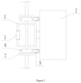
- FIG. 3 is a front view of FIG. 2 ;
- FIG. 4 is a schematic diagram of the structure of the micro warehouse in the lift shaft
- 1 lift shaft; 2 . Load device; 3 . Chain; 4 . Sprocket; 5 . Connecting frame; 6 . Roller; 7 . Track; 8 . inclined support rod; 9 . support wheel; 10 . pull rod; 11 . micro warehouse.
- the purpose of the present invention is to provide a bulk lifting transportation system used in buildings to solve the problems existing in the prior art.
- the process of transferring the load device from the storage room and its temporary connection/separation in the traditional lifting transportation device is omitted. It greatly saves the time required for single lifting transportation, and can significantly improve transportation efficiency.
- this embodiment provides a bulk lifting transportation system applied to buildings, including lift shaft 1 .
- a number of pick-up openings are evenly arranged on the sidewall of lift shaft 1 from top to bottom, and each pick-up opening is respectively corresponding to each floor of the building;
- lift shaft 1 is provided with a driving mechanism, a reversing mechanism, and its transport belt.
- the driving mechanism and the reversing mechanism are respectively arranged at the two ends of lift shaft 1 .
- Either the driving mechanism and the reversing mechanism can be installed on the top of lift shaft 1 .
- the transport belt bypassing the reversing mechanism, both ends are connected with the driving mechanism;
- the conveyor belt is provided with loading device 2 for placing goods at intervals.
- the number of loading device 2 is the same as the number of floors of the building, and the distance between adjacent loading device 2 is equal to the distance between adjacent pick-up openings. Generally, it is the height of the floor.
- the loading device 2 corresponding to the highest floor is in the cargo area. Put the goods to be transported into the corresponding loading device 2 in the order from high to low. For example, if the building has a total of 33 floors, there are 33 load-carrying devices 2 correspondingly; Before the cargo is transported, the loading device 2 corresponds to the 33rd floor is located in the cargo delivery area. After the cargo is dropped, the driving mechanism drives the conveyor belt to move, so that the next cargo device 2 that needs to drop cargo moves to the cargo delivery area. And repeat this process. If there is no cargo to be transported on a certain floor or a few floors, skip the loading device 2 of the corresponding floor; When all the goods are put in, the driving mechanism drives the conveyor belt to move. When the topmost loading device 2 reaches the topmost layer, all loading device 2 arrive at the corresponding floor at the same time. Thus, it can be lifted at one time, and the goods on different floors can be delivered at the same time.
- this embodiment can accomplish the delivery of goods to each floor. It prevents the delivery personnel from occupying the elevator, which can reduce the burden of the elevator during peak hours, and reduce the labor intensity of the express personnel and improve delivery efficiency.
- lift shaft 1 disclosed in this embodiment is provided with a reversing mechanism
- the conveyor belt can be wound around it for turning.
- the two sides of lift shaft 1 are divided into the transportation side and the temporary side according to their functions.
- all the loading device 2 are on the temporary side.
- the driving mechanism drives the conveyor belt to move. Make the load device 2 move to the transport side one by one to receive the goods and perform lifting operations.
- loading device 2 returns to the temporary side; Therefore, in this embodiment, by arranging the reversing mechanism and its transport belt in lift shaft 1 , all loading device 2 can be fixed on the transport belt.
- loading device 2 when loading device 2 is transferred from the transport side to the temporary side, it will flip under the reversing action of the reversing mechanism. Nonetheless, there are no movable parts inside loading device 2 . So even if it occurs, turning over will not affect its normal use.
- the goods targeted by this embodiment are generally small in volume and low in quality, such as express delivery, fruits and vegetables, food, and so on.
- the width and length of loading device 2 can be set according to the size of the actual lift shaft 1 .
- a servo control system is also provided.
- the servo control system is electrically connected with the driving mechanism to control the lifting of the driving structure; Regarding the above two lifting methods, you can switch the mode of the servo control system or manually control; lift shaft 1 and the loading device 1 also need to be equipped with floor sensors, encoders and leveling sensors, which are used for distance measurement and leveling. Each sensor can be electrically connected to the servo control system. If it cannot be electrically connected, it can output a wireless signal for signal transmission.
- Those skilled in the art can choose by themselves;
- the setting of the control program in the servo control system, the connection between the servo control system, various sensors, and electrical components are well known to those skilled in the art. These will not be described in detail in this embodiment.
- the driving mechanism in this embodiment includes the traction machine set on the top of lift shaft 1 .
- the conveyor belt includes a chain 3 .
- the carrying device 2 can be directly fixed on chain 3 , and a connecting frame 5 or other mechanisms can be arranged on chain 3 to fix the carrying device 2 ;
- the reversing mechanism includes a sprocket 4 arranged at the bottom of lift shaft 1 . After chain 3 bypasses the sprocket 4 , the two ends are respectively fixed to the two ends of the steel cable on the traction machine. When lifting, one end of chain 3 rises, and the other end falls.
- the driving mechanism can also be selected as the sprocket 4 .
- the sprocket 4 can be provided with one or multiple vertically.
- the sprocket 4 drives chain 3 to circulate in lift shaft 1 (cyclic movement); And chain 3 can be provided with one or more.
- the driving mechanism is not limited to the traction machine. It can also be a linear motor. Both ends of the conveyor belt are driven by two linear motors. When working, one linear motor drives the conveyor belt up while the other side linear motor drives the conveyor belt down. Vice versa.
- the connecting frame 5 includes a rotating lift shaft.
- the two ends of the rotating lift shaft are provided with rollers 6
- lift shaft 1 is also provided with a track 7 .
- Track 7 is fixed on the inner wall of lift shaft 1 by a bracket and is arranged along chain 3 . It is located on both sides of chain 3 .
- the two roller 6 are respectively arranged in the two track 7 and move along the track 7 ; Track 7 can improve transportation stability of chain 3 and prevent shaking when it goes higher.
- the bottom of the load device 2 is fixedly connected to two inclined support rods 8 .
- the end of the inclined support rod 8 is provided with a support wheel 9 , and the support wheel 9 abuts on track 7 .
- track 7 has a concave-shaped structure.
- Roller 6 abuts against the inner surface of the concave-shaped structure, and the support wheel 9 abuts against the outer surface of the concave-shaped structure;
- the bottom of the load device 2 is also provided with a pull rod 10 .
- the end of the pull rod 10 is connected to the inclined support rod 8 and is arranged close to the support wheel 9 ;
- the pull rod 10 and the inclined support rod 8 form a triangular support structure, which can make loading device 2 stronger.
- this embodiment is also provided with a micro warehouse 11 for temporarily storing goods at the pick-up opening of lift shaft 1 .
- the front and rear ends of the micro warehouse 11 are respectively provided with a front opening and a rear opening.
- the rear opening is internally connected with lift shaft 1 .
- the front opening is located on the floor, and the goods can be taken out through the front opening;
- the feeding device includes a horizontally placed cargo pushing cylinder.
- the end of the piston rod of the cargo pushing cylinder is directly opposite to the rear opening.
- the loading device 2 is also provided with a control module for controlling the movement of the cargo pushing cylinder; After loading device 2 is aligned with the micro warehouse 11 , it will open.
- the control module controls the extension of the pickup piston rod to send the goods into the micro warehouse 11 .
- the front opening of the micro warehouse 11 is provided with a front door
- the rear opening is provided with a rear door that can be opened inward.
- both the front door and the rear door are made of fireproof materials.
- the rear door is hinged with the sidewall of the micro warehouse 11 , and a reset pressure spring is arranged on the hinge axis. After the cargo is pushed in by the cargo pushing cylinder, the rear door can be automatically reset. In order to ensure the safety of the goods, an electronic lock is installed on the front door.
Landscapes
- Engineering & Computer Science (AREA)
- Structural Engineering (AREA)
- Civil Engineering (AREA)
- Mechanical Engineering (AREA)
- Architecture (AREA)
- Automation & Control Theory (AREA)
- Intermediate Stations On Conveyors (AREA)
Abstract
Description
Claims (5)
Applications Claiming Priority (2)
| Application Number | Priority Date | Filing Date | Title |
|---|---|---|---|
| CN202110629582.X | 2021-06-07 | ||
| CN202110629582.XA CN113184665A (en) | 2021-06-07 | 2021-06-07 | Batch lifting and transporting system applied to buildings |
Publications (2)
| Publication Number | Publication Date |
|---|---|
| US20220388813A1 US20220388813A1 (en) | 2022-12-08 |
| US12054360B2 true US12054360B2 (en) | 2024-08-06 |
Family
ID=76976375
Family Applications (1)
| Application Number | Title | Priority Date | Filing Date |
|---|---|---|---|
| US17/527,184 Active 2042-11-26 US12054360B2 (en) | 2021-06-07 | 2021-11-16 | Bulk lifting transportation system applied in buildings |
Country Status (2)
| Country | Link |
|---|---|
| US (1) | US12054360B2 (en) |
| CN (1) | CN113184665A (en) |
Citations (2)
| Publication number | Priority date | Publication date | Assignee | Title |
|---|---|---|---|---|
| US1946982A (en) * | 1929-10-10 | 1934-02-13 | Patrick J Campbell | Elevator system |
| GB2169867A (en) * | 1985-01-22 | 1986-07-23 | Robert Patrick Hyde | Lifting method and apparatus |
-
2021
- 2021-06-07 CN CN202110629582.XA patent/CN113184665A/en not_active Withdrawn
- 2021-11-16 US US17/527,184 patent/US12054360B2/en active Active
Patent Citations (2)
| Publication number | Priority date | Publication date | Assignee | Title |
|---|---|---|---|---|
| US1946982A (en) * | 1929-10-10 | 1934-02-13 | Patrick J Campbell | Elevator system |
| GB2169867A (en) * | 1985-01-22 | 1986-07-23 | Robert Patrick Hyde | Lifting method and apparatus |
Also Published As
| Publication number | Publication date |
|---|---|
| US20220388813A1 (en) | 2022-12-08 |
| CN113184665A (en) | 2021-07-30 |
Similar Documents
| Publication | Publication Date | Title |
|---|---|---|
| CN104029974B (en) | Automatic stereowarehouse and goods access method thereof | |
| CN109775223B (en) | Steel coil three-dimensional bin capable of being transported internally and steel coil warehousing method thereof | |
| CN110356754A (en) | Goods picking system and method | |
| CN209721259U (en) | Dumbwaiter | |
| CN208103037U (en) | Cargo unit buffer storage and warehousing system | |
| CN107416405A (en) | A kind of shuttle plate vertical library | |
| CN105083902A (en) | Ground-type roller conveying mechanism suitable for floor slab arrangement | |
| CN110342163A (en) | Cargo unit buffer storage, warehousing system and inventory's method | |
| CN108891339A (en) | A kind of shared bicycle transfer car(buggy) cabinet | |
| CN111620073A (en) | Cargo distribution system and distribution method for high-rise building | |
| CN209889764U (en) | Connection transfer system | |
| CN106672520A (en) | Logistic express transportation device | |
| US12054360B2 (en) | Bulk lifting transportation system applied in buildings | |
| CN209905643U (en) | An automated storage system | |
| CN109264553B (en) | Goods lift that can load and unload goods automatically | |
| JPH09125733A (en) | Underground multi-story parking device | |
| CN213201282U (en) | Cargo distribution system for high-rise building | |
| JP2843498B2 (en) | Article transfer equipment | |
| JP2778359B2 (en) | Automatic warehouse equipment | |
| CN117163528A (en) | Steel pipe yardage roll transport buffer memory system | |
| JP3994458B2 (en) | Operation method of vertical and horizontal transfer device | |
| KR20050008152A (en) | Parking apparatus with vertically sliding support | |
| CN115924373A (en) | Hoist, three-dimensional storage device and storage system | |
| JPS62222908A (en) | Taking-in, storing and taking-out device | |
| CN104029972B (en) | A carrier and its screw lifting device |
Legal Events
| Date | Code | Title | Description |
|---|---|---|---|
| FEPP | Fee payment procedure |
Free format text: ENTITY STATUS SET TO UNDISCOUNTED (ORIGINAL EVENT CODE: BIG.); ENTITY STATUS OF PATENT OWNER: MICROENTITY |
|
| FEPP | Fee payment procedure |
Free format text: ENTITY STATUS SET TO MICRO (ORIGINAL EVENT CODE: MICR); ENTITY STATUS OF PATENT OWNER: MICROENTITY |
|
| STPP | Information on status: patent application and granting procedure in general |
Free format text: DOCKETED NEW CASE - READY FOR EXAMINATION |
|
| STPP | Information on status: patent application and granting procedure in general |
Free format text: NON FINAL ACTION MAILED |
|
| STPP | Information on status: patent application and granting procedure in general |
Free format text: RESPONSE TO NON-FINAL OFFICE ACTION ENTERED AND FORWARDED TO EXAMINER |
|
| STPP | Information on status: patent application and granting procedure in general |
Free format text: FINAL REJECTION MAILED |
|
| STPP | Information on status: patent application and granting procedure in general |
Free format text: RESPONSE AFTER FINAL ACTION FORWARDED TO EXAMINER |
|
| STPP | Information on status: patent application and granting procedure in general |
Free format text: NOTICE OF ALLOWANCE MAILED -- APPLICATION RECEIVED IN OFFICE OF PUBLICATIONS |
|
| ZAAB | Notice of allowance mailed |
Free format text: ORIGINAL CODE: MN/=. |
|
| STPP | Information on status: patent application and granting procedure in general |
Free format text: PUBLICATIONS -- ISSUE FEE PAYMENT RECEIVED |
|
| STCF | Information on status: patent grant |
Free format text: PATENTED CASE |