US11970266B2 - Unmanned aerial vehicle, flight control mechanism for unmanned aerial vehicle, and method for using unmanned aerial vehicle and mechanism for unmanned aerial vehicle - Google Patents
Unmanned aerial vehicle, flight control mechanism for unmanned aerial vehicle, and method for using unmanned aerial vehicle and mechanism for unmanned aerial vehicle Download PDFInfo
- Publication number
- US11970266B2 US11970266B2 US17/046,384 US201817046384A US11970266B2 US 11970266 B2 US11970266 B2 US 11970266B2 US 201817046384 A US201817046384 A US 201817046384A US 11970266 B2 US11970266 B2 US 11970266B2
- Authority
- US
- United States
- Prior art keywords
- unmanned aerial
- aerial vehicle
- vehicle body
- boundary surface
- holding member
- Prior art date
- Legal status (The legal status is an assumption and is not a legal conclusion. Google has not performed a legal analysis and makes no representation as to the accuracy of the status listed.)
- Active, expires
Links
- 230000007246 mechanism Effects 0.000 title claims abstract description 44
- RZVHIXYEVGDQDX-UHFFFAOYSA-N 9,10-anthraquinone Chemical compound C1=CC=C2C(=O)C3=CC=CC=C3C(=O)C2=C1 RZVHIXYEVGDQDX-UHFFFAOYSA-N 0.000 title claims abstract description 40
- 238000000034 method Methods 0.000 title claims abstract description 22
- 230000007274 generation of a signal involved in cell-cell signaling Effects 0.000 claims description 5
- 230000005540 biological transmission Effects 0.000 claims description 4
- 230000004044 response Effects 0.000 abstract description 7
- 239000010865 sewage Substances 0.000 description 37
- 238000010586 diagram Methods 0.000 description 33
- 238000007689 inspection Methods 0.000 description 14
- 238000004891 communication Methods 0.000 description 11
- 230000000052 comparative effect Effects 0.000 description 8
- XLYOFNOQVPJJNP-UHFFFAOYSA-N water Substances O XLYOFNOQVPJJNP-UHFFFAOYSA-N 0.000 description 8
- 238000006243 chemical reaction Methods 0.000 description 6
- 230000006870 function Effects 0.000 description 6
- 239000000463 material Substances 0.000 description 4
- 230000000694 effects Effects 0.000 description 3
- 230000005484 gravity Effects 0.000 description 3
- 238000005096 rolling process Methods 0.000 description 3
- 238000000926 separation method Methods 0.000 description 3
- 241000287531 Psittacidae Species 0.000 description 2
- 230000008859 change Effects 0.000 description 2
- 230000003247 decreasing effect Effects 0.000 description 2
- 230000002265 prevention Effects 0.000 description 2
- 238000011179 visual inspection Methods 0.000 description 2
- WHXSMMKQMYFTQS-UHFFFAOYSA-N Lithium Chemical compound [Li] WHXSMMKQMYFTQS-UHFFFAOYSA-N 0.000 description 1
- HBBGRARXTFLTSG-UHFFFAOYSA-N Lithium ion Chemical compound [Li+] HBBGRARXTFLTSG-UHFFFAOYSA-N 0.000 description 1
- 230000001133 acceleration Effects 0.000 description 1
- 230000008901 benefit Effects 0.000 description 1
- 239000007789 gas Substances 0.000 description 1
- 238000007654 immersion Methods 0.000 description 1
- 238000003780 insertion Methods 0.000 description 1
- 230000037431 insertion Effects 0.000 description 1
- 229910052744 lithium Inorganic materials 0.000 description 1
- 229910001416 lithium ion Inorganic materials 0.000 description 1
- 238000012423 maintenance Methods 0.000 description 1
- 229910052751 metal Inorganic materials 0.000 description 1
- 239000002184 metal Substances 0.000 description 1
- 238000012856 packing Methods 0.000 description 1
- 229920000642 polymer Polymers 0.000 description 1
- 238000012545 processing Methods 0.000 description 1
- 230000009467 reduction Effects 0.000 description 1
- 239000002341 toxic gas Substances 0.000 description 1
Images


Classifications
-
- E—FIXED CONSTRUCTIONS
- E03—WATER SUPPLY; SEWERAGE
- E03F—SEWERS; CESSPOOLS
- E03F7/00—Other installations or implements for operating sewer systems, e.g. for preventing or indicating stoppage; Emptying cesspools
- E03F7/12—Installations enabling inspection personnel to drive along sewer canals
-
- B—PERFORMING OPERATIONS; TRANSPORTING
- B64—AIRCRAFT; AVIATION; COSMONAUTICS
- B64C—AEROPLANES; HELICOPTERS
- B64C39/00—Aircraft not otherwise provided for
- B64C39/02—Aircraft not otherwise provided for characterised by special use
- B64C39/024—Aircraft not otherwise provided for characterised by special use of the remote controlled vehicle type, i.e. RPV
-
- B—PERFORMING OPERATIONS; TRANSPORTING
- B64—AIRCRAFT; AVIATION; COSMONAUTICS
- B64C—AEROPLANES; HELICOPTERS
- B64C25/00—Alighting gear
- B64C25/02—Undercarriages
- B64C25/08—Undercarriages non-fixed, e.g. jettisonable
-
- B—PERFORMING OPERATIONS; TRANSPORTING
- B64—AIRCRAFT; AVIATION; COSMONAUTICS
- B64C—AEROPLANES; HELICOPTERS
- B64C25/00—Alighting gear
- B64C25/32—Alighting gear characterised by elements which contact the ground or similar surface
- B64C25/34—Alighting gear characterised by elements which contact the ground or similar surface wheeled type, e.g. multi-wheeled bogies
-
- B—PERFORMING OPERATIONS; TRANSPORTING
- B64—AIRCRAFT; AVIATION; COSMONAUTICS
- B64C—AEROPLANES; HELICOPTERS
- B64C27/00—Rotorcraft; Rotors peculiar thereto
- B64C27/04—Helicopters
- B64C27/08—Helicopters with two or more rotors
-
- B—PERFORMING OPERATIONS; TRANSPORTING
- B64—AIRCRAFT; AVIATION; COSMONAUTICS
- B64C—AEROPLANES; HELICOPTERS
- B64C27/00—Rotorcraft; Rotors peculiar thereto
- B64C27/20—Rotorcraft characterised by having shrouded rotors, e.g. flying platforms
-
- B—PERFORMING OPERATIONS; TRANSPORTING
- B64—AIRCRAFT; AVIATION; COSMONAUTICS
- B64U—UNMANNED AERIAL VEHICLES [UAV]; EQUIPMENT THEREFOR
- B64U50/00—Propulsion; Power supply
- B64U50/10—Propulsion
- B64U50/13—Propulsion using external fans or propellers
- B64U50/14—Propulsion using external fans or propellers ducted or shrouded
-
- E—FIXED CONSTRUCTIONS
- E03—WATER SUPPLY; SEWERAGE
- E03F—SEWERS; CESSPOOLS
- E03F7/00—Other installations or implements for operating sewer systems, e.g. for preventing or indicating stoppage; Emptying cesspools
-
- F—MECHANICAL ENGINEERING; LIGHTING; HEATING; WEAPONS; BLASTING
- F16—ENGINEERING ELEMENTS AND UNITS; GENERAL MEASURES FOR PRODUCING AND MAINTAINING EFFECTIVE FUNCTIONING OF MACHINES OR INSTALLATIONS; THERMAL INSULATION IN GENERAL
- F16L—PIPES; JOINTS OR FITTINGS FOR PIPES; SUPPORTS FOR PIPES, CABLES OR PROTECTIVE TUBING; MEANS FOR THERMAL INSULATION IN GENERAL
- F16L55/00—Devices or appurtenances for use in, or in connection with, pipes or pipe systems
- F16L55/26—Pigs or moles, i.e. devices movable in a pipe or conduit with or without self-contained propulsion means
- F16L55/28—Constructional aspects
- F16L55/30—Constructional aspects of the propulsion means, e.g. towed by cables
- F16L55/38—Constructional aspects of the propulsion means, e.g. towed by cables driven by fluid pressure
-
- G—PHYSICS
- G05—CONTROLLING; REGULATING
- G05D—SYSTEMS FOR CONTROLLING OR REGULATING NON-ELECTRIC VARIABLES
- G05D1/00—Control of position, course, altitude or attitude of land, water, air or space vehicles, e.g. using automatic pilots
- G05D1/40—Control within particular dimensions
- G05D1/48—Control of altitude or depth
- G05D1/482—Control of altitude or depth utilising or compensating for ground effect
-
- H—ELECTRICITY
- H04—ELECTRIC COMMUNICATION TECHNIQUE
- H04N—PICTORIAL COMMUNICATION, e.g. TELEVISION
- H04N23/00—Cameras or camera modules comprising electronic image sensors; Control thereof
- H04N23/90—Arrangement of cameras or camera modules, e.g. multiple cameras in TV studios or sports stadiums
-
- H—ELECTRICITY
- H04—ELECTRIC COMMUNICATION TECHNIQUE
- H04N—PICTORIAL COMMUNICATION, e.g. TELEVISION
- H04N7/00—Television systems
- H04N7/18—Closed-circuit television [CCTV] systems, i.e. systems in which the video signal is not broadcast
- H04N7/181—Closed-circuit television [CCTV] systems, i.e. systems in which the video signal is not broadcast for receiving images from a plurality of remote sources
-
- H—ELECTRICITY
- H04—ELECTRIC COMMUNICATION TECHNIQUE
- H04N—PICTORIAL COMMUNICATION, e.g. TELEVISION
- H04N7/00—Television systems
- H04N7/18—Closed-circuit television [CCTV] systems, i.e. systems in which the video signal is not broadcast
- H04N7/183—Closed-circuit television [CCTV] systems, i.e. systems in which the video signal is not broadcast for receiving images from a single remote source
- H04N7/185—Closed-circuit television [CCTV] systems, i.e. systems in which the video signal is not broadcast for receiving images from a single remote source from a mobile camera, e.g. for remote control
-
- B—PERFORMING OPERATIONS; TRANSPORTING
- B64—AIRCRAFT; AVIATION; COSMONAUTICS
- B64D—EQUIPMENT FOR FITTING IN OR TO AIRCRAFT; FLIGHT SUITS; PARACHUTES; ARRANGEMENT OR MOUNTING OF POWER PLANTS OR PROPULSION TRANSMISSIONS IN AIRCRAFT
- B64D43/00—Arrangements or adaptations of instruments
-
- B—PERFORMING OPERATIONS; TRANSPORTING
- B64—AIRCRAFT; AVIATION; COSMONAUTICS
- B64D—EQUIPMENT FOR FITTING IN OR TO AIRCRAFT; FLIGHT SUITS; PARACHUTES; ARRANGEMENT OR MOUNTING OF POWER PLANTS OR PROPULSION TRANSMISSIONS IN AIRCRAFT
- B64D47/00—Equipment not otherwise provided for
- B64D47/08—Arrangements of cameras
-
- B—PERFORMING OPERATIONS; TRANSPORTING
- B64—AIRCRAFT; AVIATION; COSMONAUTICS
- B64U—UNMANNED AERIAL VEHICLES [UAV]; EQUIPMENT THEREFOR
- B64U10/00—Type of UAV
- B64U10/10—Rotorcrafts
- B64U10/13—Flying platforms
-
- B—PERFORMING OPERATIONS; TRANSPORTING
- B64—AIRCRAFT; AVIATION; COSMONAUTICS
- B64U—UNMANNED AERIAL VEHICLES [UAV]; EQUIPMENT THEREFOR
- B64U20/00—Constructional aspects of UAVs
- B64U20/30—Constructional aspects of UAVs for safety, e.g. with frangible components
-
- B—PERFORMING OPERATIONS; TRANSPORTING
- B64—AIRCRAFT; AVIATION; COSMONAUTICS
- B64U—UNMANNED AERIAL VEHICLES [UAV]; EQUIPMENT THEREFOR
- B64U2101/00—UAVs specially adapted for particular uses or applications
- B64U2101/25—UAVs specially adapted for particular uses or applications for manufacturing or servicing
- B64U2101/26—UAVs specially adapted for particular uses or applications for manufacturing or servicing for manufacturing, inspections or repairs
-
- B—PERFORMING OPERATIONS; TRANSPORTING
- B64—AIRCRAFT; AVIATION; COSMONAUTICS
- B64U—UNMANNED AERIAL VEHICLES [UAV]; EQUIPMENT THEREFOR
- B64U2101/00—UAVs specially adapted for particular uses or applications
- B64U2101/30—UAVs specially adapted for particular uses or applications for imaging, photography or videography
-
- B—PERFORMING OPERATIONS; TRANSPORTING
- B64—AIRCRAFT; AVIATION; COSMONAUTICS
- B64U—UNMANNED AERIAL VEHICLES [UAV]; EQUIPMENT THEREFOR
- B64U2201/00—UAVs characterised by their flight controls
- B64U2201/10—UAVs characterised by their flight controls autonomous, i.e. by navigating independently from ground or air stations, e.g. by using inertial navigation systems [INS]
-
- B—PERFORMING OPERATIONS; TRANSPORTING
- B64—AIRCRAFT; AVIATION; COSMONAUTICS
- B64U—UNMANNED AERIAL VEHICLES [UAV]; EQUIPMENT THEREFOR
- B64U2201/00—UAVs characterised by their flight controls
- B64U2201/20—Remote controls
-
- B—PERFORMING OPERATIONS; TRANSPORTING
- B64—AIRCRAFT; AVIATION; COSMONAUTICS
- B64U—UNMANNED AERIAL VEHICLES [UAV]; EQUIPMENT THEREFOR
- B64U30/00—Means for producing lift; Empennages; Arrangements thereof
- B64U30/20—Rotors; Rotor supports
-
- B—PERFORMING OPERATIONS; TRANSPORTING
- B64—AIRCRAFT; AVIATION; COSMONAUTICS
- B64U—UNMANNED AERIAL VEHICLES [UAV]; EQUIPMENT THEREFOR
- B64U30/00—Means for producing lift; Empennages; Arrangements thereof
- B64U30/20—Rotors; Rotor supports
- B64U30/21—Rotary wings
-
- B—PERFORMING OPERATIONS; TRANSPORTING
- B64—AIRCRAFT; AVIATION; COSMONAUTICS
- B64U—UNMANNED AERIAL VEHICLES [UAV]; EQUIPMENT THEREFOR
- B64U50/00—Propulsion; Power supply
- B64U50/10—Propulsion
- B64U50/13—Propulsion using external fans or propellers
-
- B—PERFORMING OPERATIONS; TRANSPORTING
- B64—AIRCRAFT; AVIATION; COSMONAUTICS
- B64U—UNMANNED AERIAL VEHICLES [UAV]; EQUIPMENT THEREFOR
- B64U50/00—Propulsion; Power supply
- B64U50/30—Supply or distribution of electrical power
-
- F—MECHANICAL ENGINEERING; LIGHTING; HEATING; WEAPONS; BLASTING
- F16—ENGINEERING ELEMENTS AND UNITS; GENERAL MEASURES FOR PRODUCING AND MAINTAINING EFFECTIVE FUNCTIONING OF MACHINES OR INSTALLATIONS; THERMAL INSULATION IN GENERAL
- F16L—PIPES; JOINTS OR FITTINGS FOR PIPES; SUPPORTS FOR PIPES, CABLES OR PROTECTIVE TUBING; MEANS FOR THERMAL INSULATION IN GENERAL
- F16L2101/00—Uses or applications of pigs or moles
- F16L2101/30—Inspecting, measuring or testing
-
- G—PHYSICS
- G05—CONTROLLING; REGULATING
- G05D—SYSTEMS FOR CONTROLLING OR REGULATING NON-ELECTRIC VARIABLES
- G05D2105/00—Specific applications of the controlled vehicles
- G05D2105/80—Specific applications of the controlled vehicles for information gathering, e.g. for academic research
- G05D2105/89—Specific applications of the controlled vehicles for information gathering, e.g. for academic research for inspecting structures, e.g. wind mills, bridges, buildings or vehicles
-
- G—PHYSICS
- G05—CONTROLLING; REGULATING
- G05D—SYSTEMS FOR CONTROLLING OR REGULATING NON-ELECTRIC VARIABLES
- G05D2107/00—Specific environments of the controlled vehicles
- G05D2107/50—Confined spaces, e.g. tanks, pipelines, tunnels or containers
-
- G—PHYSICS
- G05—CONTROLLING; REGULATING
- G05D—SYSTEMS FOR CONTROLLING OR REGULATING NON-ELECTRIC VARIABLES
- G05D2109/00—Types of controlled vehicles
- G05D2109/20—Aircraft, e.g. drones
- G05D2109/25—Rotorcrafts
- G05D2109/254—Flying platforms, e.g. multicopters
-
- H—ELECTRICITY
- H04—ELECTRIC COMMUNICATION TECHNIQUE
- H04N—PICTORIAL COMMUNICATION, e.g. TELEVISION
- H04N23/00—Cameras or camera modules comprising electronic image sensors; Control thereof
- H04N23/50—Constructional details
- H04N23/555—Constructional details for picking-up images in sites, inaccessible due to their dimensions or hazardous conditions, e.g. endoscopes or borescopes
Definitions
- the present invention relates to an unmanned aerial vehicle, a flight control mechanism for an unmanned aerial vehicle, and a method for using an unmanned aerial vehicle and a mechanism for an unmanned aerial vehicle. More specifically, the present invention relates to a flight control mechanism for controlling flight of an unmanned aerial vehicle, an unmanned aerial vehicle with the mechanism and a method using them in an environment including the inside of a closed-type space such as the inside of a tubular space or the inside of a rectangular space where collisions with some boundary surface may occur.
- the useful life of a sewage pipeline (sewer conduit) is set to approximately 50 years, and it is assumed that facilities that have reached the end of their useful life will exponentially increases in the future. For efficient maintenance and management, it is essential to grasp a state of the sewage pipeline.
- a method of inspecting the state of the sewage pipeline As a method of inspecting the state of the sewage pipeline, a method of an inspector moving in a pipe to perform direct visual inspection, a method of arranging a television camera connected to the ground via a cable in a pipe to perform shooting, a method of loading a television camera connected to the ground via a cable into a self-propelled vehicle and arranging the television camera in a pipe to perform shooting while traveling, and the like have been used.
- the method of the direct visual inspection by the inspector there are various problems such as a risk of a toxic gas being produced in the sewage pipeline to affect a human body and a risk from immersion at the time of sudden rainfall.
- the method of arranging the television camera in the pipe there are also problems that a sufficient inspection speed is not obtained and a vehicle is difficult to control when a water level in the sewage pipeline rises.
- controllability of the unmanned aerial vehicle may be deteriorated by the collision with the boundary surface, or an vehicle body may be damaged in some cases.
- Patent Literature 1 Japanese Patent Laid-Open No. 2017-087917
- Patent Literature 2 Japanese Patent Laid-Open No. 2017-226259
- Patent Literature 3 Japanese Patent Laid-Open No. 2018-001967
- An object of the present invention is to provide a flight control mechanism for controlling flight of an unmanned aerial vehicle by controlling collisions with boundary surfaces, an unmanned aerial vehicle with the mechanism and a method using them.
- the present invention provides a flight control mechanism for an unmanned aerial vehicle comprising: a first preceding collision member; a second preceding collision member; and a holding member which holds the first and the second preceding collision members with a distance above a vehicle body of an unmanned aerial vehicle, wherein the holding member can be inclined with respect to the vehicle body by rotating toward the lateral side of the vehicle body around a predetermined position in the vehicle body or on the vehicle body, and the holding member rotates responsive to one of the first and the second preceding collision members colliding with a boundary surface.
- the holding member may be configured to rotate responsive to one of the first and the second preceding collision members colliding with the boundary surface so that both of the first and the second preceding collision members touch the boundary surface according to ascension of the vehicle body.
- the first and the second preceding collision members may be rotary members, and the flight control mechanism may be configured so that the first and the second rotary members rotate when the unmanned aerial vehicle flies while the first and the second rotary members are touching the boundary surface.
- the present invention provides the unmanned aerial vehicle comprising two or more flight control mechanisms in front and behind with a distance, wherein the unmanned aerial vehicle is configured to fly along the boundary surface by flying with first and the second preceding collision members of the respective flight control mechanisms touching the boundary surface.
- the unmanned aerial vehicle may be configured as an unmanned aerial vehicle comprising: at least four rotary wings; a drive device which drives the rotary wings; and a control signal generation unit which generates a control signal for causing the drive device to drive the rotary wings.
- the unmanned aerial vehicle may comprise: two sets of rotary wings as the at least four rotary wings where each set consists of two rotary wings distanced in left and right; and the flight control mechanism for each one set of the two sets wherein in each set, the predetermined position is below the positions of the two rotary wings included in that set in a state where the vehicle body is not inclined.
- the control signal may include an attitude control signal
- the unmanned aerial vehicle may be configured to control the attitude of the unmanned aerial vehicle by causing the drive device to drive the rotary wings with the attitude control signal to reduce the number of rotations of at least one or some of the rotary wings when the unmanned aerial vehicle is inclined.
- the drive device may include a plurality of motors which respective motors provide the respective rotary wings with motive powers, respectively, and respective motors may be configured to provide respective rotary wings with motive powers, respectively, at a position with a higher gravitational potential than the rotary wing which receives motive power from the each motor.
- the unmanned aerial vehicle may further comprise a thrust generation propeller, and the unmanned aerial vehicle may be configured to propel by rotations of the thrust generation propeller while floating by rotations of the at least four rotary wings.
- the unmanned aerial vehicle may further comprise a shooting camera and may be configured to fly inside a closed-type space by driving the rotary wings while shooting inside the closed-type space using the shooting camera.
- the unmanned aerial vehicle may further comprises a traveling direction shooting camera and a traveling direction shooting data transmission unit, and the unmanned aerial vehicle may be configured to fly while shooting in the traveling direction by means of the traveling direction shooting camera and transmitting obtained traveling direction shooting data from the traveling direction shooting data transmission unit to the outside.
- the present invention provides a method for flying an unmanned aerial vehicle along a boundary surface
- the unmanned aerial vehicle comprises two or more flight control mechanisms in front and behind with a distance
- each flight control mechanism comprises:
- a holding member which holds the first and the second preceding collision members separately above a vehicle body of an unmanned aerial vehicle, wherein the holding member can be inclined with respect to the vehicle body by rotating toward the lateral side of the vehicle body around a predetermined position in the vehicle body or on the vehicle body, and the holding member rotates responsive to one of the first and the second preceding collision members colliding with a boundary surface and makes both of the first and the second preceding collision members touch the boundary surface according to ascension of the vehicle body,
- the method comprises flying the unmanned aerial vehicle in a state where the first and the second preceding collision members of the respective flight control mechanisms are touching the boundary surface.
- the risk of damages to the vehicle body, reduction of controllability etc. according to collisions when flying the unmanned aerial vehicle in an environment where collisions with a boundary surface may occur is at least reduced.
- FIG. 1 A is a perspective view of an unmanned aerial vehicle according to an embodiment of the present embodiment.
- FIG. 1 B is a diagram of the unmanned aerial vehicle illustrated in FIG. 1 A in a positive direction of z.
- FIG. 1 C is a diagram of the unmanned aerial vehicle illustrated in FIG. 1 A in a positive direction of y.
- FIG. 1 D is a perspective view of the unmanned aerial vehicle illustrated in FIG. 1 A from behind in a traveling direction.
- FIG. 1 E is a perspective view of the unmanned aerial vehicle illustrated in FIG. 1 A in a negative direction of z.
- FIG. 1 F is a perspective view of the unmanned aerial vehicle illustrated in FIG. 1 A in the negative direction of z and in a direction different from that in FIG. 1 E .
- FIG. 2 is a diagram illustrating a holding member that holds preceding collision members (a rotary member such as a wheel or a roller) and a holding member attachment member to which the holding member is attached.
- a holding member that holds preceding collision members (a rotary member such as a wheel or a roller) and a holding member attachment member to which the holding member is attached.
- FIG. 3 A is a diagram illustrating the holding member with the preceding collision members removed.
- FIG. 3 B is a diagram illustrating the holding member, the preceding collision member (a rotary member such as a wheel or a roller) to be attached to the holding member, and a shaft section for preceding collision member as viewed in an arrow direction indicated by A in FIG. 3 A .
- the preceding collision member a rotary member such as a wheel or a roller
- FIG. 4 is a diagram illustrating the holding member to which the preceding collision members other than a rotary member such as a wheel or a roller is attached.
- FIG. 5 A is a diagram illustrating a positional relationship when a holding member is attached to an vehicle body to rotate around a position lower than a corresponding set of rotors.
- FIG. 5 B is a diagram illustrating a positional relationship when the holding member illustrated in FIG. 5 A is inclined with respect to the vehicle body.
- FIG. 5 C is a diagram illustrating a force to be exerted on each of the rotors when the inclination illustrated in FIG. 5 B has occurred during flight and a rotational direction of the vehicle body caused by the force.
- FIG. 5 D is a diagram illustrating a positional relationship when the vehicle body is inclined by a function of the force to the rotor illustrated in FIG. 5 C .
- FIG. 5 E is a conceptual diagram illustrating a principle of the inclination of the vehicle body described with reference to FIGS. 5 A to 5 D .
- FIG. 6 A is a diagram illustrating a positional relationship when a holding member is attached to an vehicle body to rotate around a position higher than a corresponding set of rotors.
- FIG. 6 B is a diagram illustrating a positional relationship when the holding member illustrated in FIG. 6 A is inclined with respect to the vehicle body.
- FIG. 6 C is a diagram illustrating a force to be exerted on each of the rotors when the inclination illustrated in FIG. 6 B has occurred during flight and a rotational direction of the vehicle body caused by the force.
- FIG. 6 D is a diagram illustrating a positional relationship when the vehicle body is inclined by the function of the force to the rotor illustrated in FIG. 6 C .
- FIG. 6 E is a conceptual diagram illustrating a principle of the inclination of the vehicle body described with reference to FIGS. 6 A to 6 D .
- FIG. 7 A is a perspective view illustrating a positional relationship between rotors and motor members in a comparative example.
- FIG. 7 B is a diagram of the rotors and the motor members illustrated in FIG. 7 A in a positive direction of x.
- FIG. 7 C is a diagram illustrating a cross section cut along a plane A-A in FIG. 7 B of the motor members illustrated in FIG. 7 A and each of the motor members.
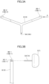
- FIG. 8 is a perspective view illustrating a positional relationship between rotors and motor members in the present embodiment.
- FIG. 9 is a block diagram illustrating a functional configuration of the unmanned aerial vehicle illustrated in FIG. 1 A .
- FIG. 10 is a diagram illustrating a structure of a sewage pipeline facility capable of flying the unmanned aerial vehicle illustrated in FIG. 1 A .
- FIG. 11 is a diagram illustrating the unmanned aerial vehicle illustrated in FIG. 1 A that flies in a tubular space in the sewage pipeline facility illustrated in FIG. 10 .
- FIG. 12 A is a diagram illustrating how a preceding collision member collides with an inner wall of a sewage pipeline during flight illustrated in FIG. 11 .
- FIG. 12 B is a diagram illustrating how the holding member rotates in response the collision illustrated in FIG. 12 A and the other preceding collision member to be held by the holding member also collides with the inner wall in response to rise of the vehicle body.
- FIG. 12 C is a diagram illustrating how the vehicle body is inclined after the holding member illustrated in FIG. 12 B is inclined.
- FIG. 13 A is a diagram illustrating how the preceding collision member collides with the inner wall of the sewage pipeline (at a position different from a collision position illustrated in FIG. 12 A ) during flight illustrated in FIG. 11 .
- FIG. 13 B is a diagram illustrating how the holding member rotates in response the collision illustrated in FIG. 13 A and the other preceding collision member to be held by the holding member also collides with the inner wall in response to rise of the vehicle body.
- FIG. 14 is a diagram illustrating how the unmanned aerial vehicle illustrated in FIG. 1 A is inclined by rotating (rolling) around an x-axis.
- FIG. 15 is a diagram illustrating an example of an image in the sewage pipeline shot by a front camera.
- an unmanned aerial vehicle, a flight control mechanism for the unmanned aerial vehicle, and a method using these according to an embodiment of the present invention will be described below with reference to the drawings.
- the unmanned aerial vehicle, the flight control mechanism for the unmanned aerial vehicle, and the method using these are not limited to a specific mode described below, but are appropriately changeable within the scope of the present invention.
- the unmanned aerial vehicle according to the present invention is not necessarily an autonomous flight type unmanned aerial vehicle, and a functional configuration of the unmanned aerial vehicle is not limited to that illustrated in FIG. 9 , but is also arbitrary if a similar operation can be performed.
- operations to be performed by a plurality of components may be performed by a single component, for example, a function of a communication unit is integrated with a main operation unit.
- an operation to be performed by a single component as illustrated may be performed by a plurality of components, for example, a function of a main operation unit is distributed among a plurality of operation units.
- An autonomous control program of the unmanned aerial vehicle may be recorded on a recording device such as a hard disk drive and read out and executed by the main operation unit (The autonomous control program as illustrated may be decomposed into a plurality of program modules, or any other programs may be executed by the main operation unit or the like.), or a similar operation may be performed by a built-in type system using a microcomputer or the like.
- All components illustrated in the following embodiment need not be included in the unmanned aerial vehicle and the flight control mechanism for the unmanned aerial vehicle according to the present invention (For example, the unmanned aerial vehicle and the flight control mechanism for the unmanned aerial vehicle need not include a thrust generation propeller 25 when propulsion of the unmanned aerial vehicle is controlled under control of rotors 13 to 16 illustrated in FIG. 1 B and need not include an autonomous control program and various types of databases if the unmanned aerial vehicle is completely flown under control from outside without performing autonomous control.), and the method according to the present invention need not include all method steps as illustrated.
- a rotary wing for floating the unmanned aerial vehicle is not limited to four rotors 13 to 16 as illustrated in FIG. 1 B , for example, but may be any number of (four or more) rotary wings.
- a propeller for generating a thrust is not limited to the thrust generation propeller 25 illustrated in FIG. 1 D , for example, but may be any propeller.
- the flight control mechanism for the unmanned aerial vehicle according to the present invention can be used for controlling any unmanned aerial vehicle such as a rotorcraft or a fixed-wing craft, and the unmanned aerial vehicle according to the present invention is not limited to the rotorcraft.
- An vehicle body size of the unmanned aerial vehicle is also arbitrary.
- the unmanned aerial vehicle can be flown in not only the closed state but also any environment and for any purpose, and the flight control mechanism can be used in not only the closed-type space but also any environment.
- the closed-type space need not be completely closed, but may be a space that is at least partially closed and where flight of the unmanned aerial vehicle is at least partially restricted.
- a tubular space in a sewage pipeline connected to the outside via a manhole is also a closed-type space
- a tunnel of a highway is also a closed-type space, as described in the following embodiment.
- the number of preceding collision members to be held by the holding member is not limited to two, but is also arbitrary, and the number of flight control mechanisms to be attached to the vehicle body is also arbitrary.
- the holding member can be formed of a metal or plastic, for example, the holding member may be formed of any material such as an elastic body if it can exhibit a function as the holding member. Other members and components may be composed of any material if they can exhibit functions of the present invention.
- FIGS. 1 A to 1 F illustrate an appearance of an unmanned aerial vehicle according to an embodiment of the present invention.
- FIG. 1 A is a perspective view
- FIG. 1 B is a diagram viewed in a positive direction of z illustrated in FIG. 1 A
- FIG. 1 C is a diagram viewed in a positive direction of y
- FIG. 1 D is a perspective view viewed from behind in a traveling direction
- FIGS. 1 E and 1 F are perspective views viewed in a negative direction of z (but in different directions) illustrated in FIG. 1 A .
- An unmanned aerial vehicle 1 is designed in dimensions of an overall width (a width in a y-direction in FIG. 1 A ) of approximately 250 mm and an overall length (a width in an x-direction in FIG.
- rotors rotary wings
- the adjacent rotors respectively rotate in opposite directions, for example, the rotors 13 and 16 rotate in a clockwise direction viewed in the positive direction of z, and the rotors 14 and 15 rotate in a counterclockwise direction viewed in the positive direction of z.
- a thrust generation propeller 25 that rotates by a drive of the motor 21 to generate a thrust of the unmanned aerial vehicle 1
- an inspection camera 22 , a front camera 23 , and a ultrasonic sensor 24 , and each of the components are integrated using a frame 4 .
- the unmanned aerial vehicle 1 further includes a holding member 9 that separates preceding collision members (a rotary member such as a wheel or a roller) 5 and 6 to hold the preceding collision members 5 and 6 above an vehicle body of the unmanned aerial vehicle 1 (the positive direction of the z-axis) and can be inclined with respect to the vehicle body by rotating toward the lateral side of the vehicle body around a predetermined position in the vehicle body or on the vehicle body (in the positive direction of y or in a negative direction of y, which need not be completely parallel to the y-direction but may intersect the x-direction) and a holding member 10 that similarly holds preceding collision members (a rotary member such as a wheel or a roller) 7 and 8 and can be similarly inclined with respect to the vehicle body with the holding member 9 and the holding member 10 separated from each other in a front-rear direction (A positive direction of x in FIG.
- a holding member 9 that separates preceding collision members (a rotary member such as a wheel or a roller) 5 and 6
- the holding member 9 is attached to the waterproof case 3 by a holding member attachment member 11 ( FIG. 1 E ), as illustrated in FIG. 1 E , and the holding member 10 is also similarly attached to the waterproof case 3 by a holding member attachment member 12 ( FIG. 1 F ).
- the number of holding members to be attached to the vehicle body is arbitrary. For example, one of the holding members 9 and 10 may be detached, only one holding member may be used by being attached to the vicinity of a center of gravity 26 of the vehicle body, or three or more holding members may be used by being attached.
- the components of the unmanned aerial vehicle 1 illustrated in FIG. 1 A excluding the holding members 9 and 10 and the preceding collision members 5 to 8 held thereby or excluding shaft sections for preceding collision member 5 A to 8 A and preceding collision member attachment members 9 B- 1 , 9 B- 2 , 10 B- 1 , and 10 B- 2 when the preceding collision members 5 to 8 , are each a rotary member such as a wheel or a roller are referred to as an “vehicle body”.
- FIG. 2 illustrates the holding member 9 that holds the preceding collision members 5 and 6 and the holding member attachment member 11 to which the holding member 9 is attached.
- the same may apply to a configuration of the holding member 10 that holds the preceding collision members 7 and 8 and the holding member attachment member 12 to which the holding member 10 is attached.
- the holding member attachment members 11 and 12 are fixed to the waterproof case 3 .
- the holding member 9 is provided with a hole 9 A. When a shaft section for holding member 11 A in the holding member attachment member 11 is inserted into the hole 9 A (See FIG. 1 E . Although the shaft section for holding member 11 A extends along the paper in FIG.
- the shaft section for holding member 11 A is inserted into the hole 9 A with the shaft section 11 A extending in a direction perpendicular to the paper.
- the holding member 9 is attached to the vehicle body.
- the holding member 9 can be inclined with respect to the vehicle body by rotating toward the lateral side of the vehicle body around a position of the hole 9 A with the shaft section for holding member 11 A used as a rotation axis (fixing axis).
- a member for separation prevention (a cap, etc.) may be further fitted in the shaft section for holding member 11 A after the holding member 9 is attached.
- rotation herein is not limited to rotation in one direction but may be rotation in both directions (in positive and negative directions in the y-direction in FIG. 1 A in an example) or may not be complete rotation by 360 degrees (The same applies to subsequent “rotation”.).
- FIG. 1 E although the holding member 9 is exposed to the top of the vehicle body (in the positive direction of z) from a hole provided in the frame 4 as illustrated in FIG. 1 A while being attached to the waterproof case 3 by the holding member attachment member 11 , rotational motion of the holding member 9 is prevented at a boundary position (rotation stop positions 4 A and 4 B) on the lateral side of the hole. Thus, the rotational motion is limited to rotation up to a predetermined maximum angle.
- the holding member 10 is also similarly exposed to the top of the vehicle body (in the positive direction of z) from a hole provided in the frame 4 while being attached to the waterproof case 3 by the holding member attachment member 12 , and rotational motion of the holding member 10 is prevented at a boundary position (rotation stop positions 4 C and 4 D (see FIG. 1 D )) on the lateral side of the hole.
- the rotational motion of the holding member 10 is also limited to rotation up to a predetermined maximum angle (The respective maximum rotational angles of the holding members 9 and 10 may differ from each other.).
- the holding member 9 with the preceding collision members 5 and 6 removed is illustrated in FIG. 3 A .
- the same may apply to the holding member 10 with the preceding collision members 7 and 8 removed.
- the holding member 9 is provided with preceding collision member attachment members 9 B- 1 and 9 B- 2 .
- the holding member 9 , the preceding collision member 5 to be attached to the holding member 9 , and the shaft section for preceding collision member 5 A as viewed in an arrow direction indicated by A in FIG. 3 A are illustrated in FIG. 311 .
- the preceding collision member 5 as a rotary member such as a wheel or a roller is fixed to the shaft section for preceding collision member 5 A, and the shaft section for preceding collision member 5 A is inserted into a hole 9 C- 1 provided in the preceding collision member attachment member 9 B- 1 in the holding member 9 (It may be passed through the hole 9 C- 1 , as illustrated in FIG. 2 .
- the shaft section for preceding collision member 5 A is inserted into the hole 9 C- 1 with the shaft section 5 A extending in the direction perpendicular to the paper.) so that the shaft section 5 A is held in the holding member 9 .
- “holding” herein does not require that the preceding collision member 5 is completely fixed to the holding member 9 but may prevent the preceding collision member 5 from completely separating from the holing member 9 and freely moving (The same applies to the other holding member and the other preceding collision members.).
- the preceding collision member (rotary member) 5 and the shaft section for preceding collision member 5 A can rotate in an integrated manner with the shaft section for preceding collision member 5 A held in the holding member 9 using the shaft section for preceding collision member 5 A as a rotation axis.
- a member for separation prevention (a cap, etc.) may be further fitted in the shaft section for preceding collision member 5 A after the preceding collision member 5 is attached to the holding member 9 as described above. The same may apply to a mode in which the holding member 9 holds the preceding collision member 6 and a mode in which the holding member 10 holds the preceding collision members 7 and 8 .
- a member other than a rotary member such as a wheel or a roller may be used as the preceding collision members 5 to 8 .
- An example in which a preceding collision member fixed to a holding member is used is illustrated in FIG. 4 as an example.
- the preceding collision members 5 and 6 are each configured as a member fixed to the holding member 9 , and are each formed of a low friction plastic material or the like. Even if the preceding collision member and the holding member each having such a configuration are used, flight control of an unmanned aerial vehicle as described below can be performed.
- the preceding collision member advances while sliding on a boundary surface (like, e.g., a sled), unlike when a rotary member such as a wheel or a roller is used.
- the preceding collision member is preferably formed of a material having a low friction between itself and the boundary surface. The same may apply in a mode in which the holding member 10 holds the preceding collision members 7 and 8 .
- the preceding collision members 5 to 8 wear out by advancing while sliding in contact with the boundary surface, the preceding collision members 5 to 8 are preferably replaced with new ones.
- the inspection camera 22 is a camera for shooting a still image or a moving image during flight in a closed-type space by the unmanned aerial vehicle 1 .
- a commercially available camera such as a GoPro session (Tajima MOTOR CORPORATION) can be used.
- the front camera 23 is a camera for shooting a still image or a moving image in a traveling direction during flight in the closed-type space by the unmanned aerial vehicle 1 .
- Data of the shot still image or moving image is transmitted to an external apparatus (e.g., a computer including a display), as needed, and an operator can steer the unmanned aerial vehicle 1 while confirming the data.
- the ultrasonic sensor 24 is a sensor for detecting an obstacle or the like ahead thereof, and can transmit a ultrasonic wave in the traveling direction during flight in the closed-type space by the unmanned aerial vehicle 1 and measure a distance from the obstacle or the like by receiving a reflected wave.
- the inspection camera 22 and the front camera 23 may be each a camera such as an infrared camera or a ultraviolet camera.
- the above-described rotation center position in each of the holding members 9 and 10 is preferably below (in the negative direction of z in FIG. 1 A ) a position of the set of rotors corresponding to the holding member with the vehicle body not inclined. A reason for that will be described below with reference to FIGS. 5 A to 5 E .
- FIG. 5 A A positional relationship when the holding member is attached to be rotatable around a position lower than the corresponding set of rotors (in the negative direction of z in FIG. 1 A ) with the vehicle body not inclined is illustrated in FIG. 5 A (viewed in the positive direction of x in FIG. 1 A ).
- description is made below using the holding member 9 and the corresponding set of rotors 13 and 14 an operation can also be described in a similar principle in the holding member 10 and the corresponding set of rotors 15 and 16 .
- respective distances between a center line of the holding member, which remains not inclined with respect to the vehicle body, and center lines of the two rotors in the corresponding set are equal to each other (in FIG.
- the holding member 9 is inclined toward the lateral side of the vehicle body due to any reason.
- forces f are respectively exerted (respectively act) on the rotors 13 and 14 , as indicated by arrows in FIG. 5 C .
- FIG. 5 B an entire configuration illustrated in FIG. 5 B is drawn in an inclined manner for convenience of illustration in FIG. 5 C , a relative inclination between the holding member 9 and the vehicle body does not change from the configuration illustrated in FIG. 5 B .
- a “distance” between the rotor 14 and the center line of the holding member 9 (a distance in a direction perpendicular to the center line of the holding member 9 between a rotation center of the rotor 14 and the center line) is b
- a “distance” between the rotor 13 and the center line of the holding member 9 (a distance in the direction perpendicular to the center line of the holding member 9 between a rotation center of the rotor 13 and the center line) is a
- a is larger than b
- a force (torque) to rotate the vehicle body in an arrow direction indicated by R in FIG. 5 C is exerted as a whole on the vehicle body.
- the force is a force to be exerted in a direction in which the inclination of the holding member 9 with respect to the vehicle body is canceled.
- a relative inclination between the holding member 9 and the vehicle body can be at least partially canceled.
- FIG. 5 E A positional relationship between the holding member 9 and the rotors 13 and 14 , including an attachment position of the holding member 9 (a position of the holding member attachment member 11 ), is illustrated in FIG. 5 E if conceptually drawn, and a principle in which the above-described relative inclination can be at least partially canceled can be understood.
- the holding member 10 when the holding member 10 is also attached to be rotatable around a position lower than a position of the corresponding set of rotors 15 and 16 (in the negative direction of z in FIG. 1 A ), a relative inclination between the holding member 10 and the vehicle body can also be at least partially canceled in a similar principle.
- FIG. 6 A viewed in the positive direction of x in FIG. 1 A .
- FIG. 6 B it is assumed that the holding member 9 is inclined toward the lateral side of the vehicle body due to any reason.
- forces f are respectively exerted (respectively act) on the rotors 13 and 14 , as indicated by an arrow in FIG. 6 C .
- FIG. 6 B Note that although an entire configuration illustrated in FIG. 6 B is drawn in an inclined manner for convenience of illustration in FIG. 6 C , a relative inclination between the holding member 9 and the vehicle body does not change from the configuration illustrated in FIG. 6 B .
- a force (torque) to rotate the vehicle body in an arrow direction indicated by R in FIG. 6 C is exerted as a whole on the vehicle body.
- the force is a force to be exerted in a direction in which inclination of the holding member 9 with respect to the vehicle body is increased.
- FIG. 6 E A positional relationship between the holding member 9 and the rotors 13 and 14 , including an attachment position of the holding member 9 (a position of the holding member attachment member 11 ), is illustrated in FIG. 6 E if conceptually drawn, and a principle in which the above-described relative inclination increases can be understood.
- the holding member 10 when the holding member 10 is also attached to be rotatable around a position higher than a position of the corresponding set of rotors 15 and 16 (in the positive direction of z in FIG. 1 A ), a relative inclination between the holding member 10 and the vehicle body increases in a similar principle.
- a configuration corresponding to FIG. 5 A is preferably adopted to cancel the relative inclination, it should be noted that the present invention can be implemented even if a configuration corresponding to FIG. 6 A is adopted.
- the motors 17 and 19 are configured to be respectively positioned above rotors 13 and 15 (at a position where a gravity potential is high) to drive the rotors 13 and 15 .
- the motors 18 and 20 are also similarly configured to be respectively positioned on the rotors 14 and 16 to drive the rotors.
- FIG. 7 A is a perspective view illustrating a positional relationship between rotors and motor members in the comparative example
- FIG. 7 B is a diagram of the rotors and the motor members illustrated in FIG. 7 A as viewed in a positive direction of x in FIG. 7 A
- FIG. 7 C is a diagram illustrating a cross section cut along a plane A-A in FIG. 7 B and each of the motor members.
- the rotors 13 , 14 , 15 , and 16 are fixed to a rod-shaped protrusion (see FIG. 7 C ) of a motor member 27 A (see FIG. 7 B ), and rotate with the rod-shaped protrusion as a rotation axis.
- the rotors 13 , 14 , 15 , and 16 receive a force in an arrow direction (in a positive direction of z) in FIG. 7 A by rotating, to pull the motor member 27 A in the same direction.
- the motor member 27 A and a motor member 27 B are fitted to each other, and do not necessarily adhere to each other. Therefore, if the motor member 27 A is pulled in the positive direction of z, the motor member 27 A may separate from the motor member 27 B.
- a motor member 27 C is used as a fastener in the configuration in the comparative example (see FIGS. 7 B and 7 C ). As illustrated in FIG.
- FIG. 8 A positional relationship between rotors and motor members in the present embodiment is illustrated in a perspective view of FIG. 8 .
- the present embodiment is similar to the comparative example except that the rotors 13 , 14 , 15 , and 16 are positioned below the motor members 27 A and 27 B and that the motor member 27 C is not used.
- the rotors 13 , 14 , 15 , and 16 are fixed to a rod-shaped protrusion (see FIG. 7 C ) of the motor member 27 A (see FIG. 7 B ), and rotate with the rod-shaped protrusion as a rotation axis.
- the rotors 13 , 14 , 15 , and 16 receive a force in an arrow direction (in a positive direction of z) in FIG.
- FIG. 9 is a block diagram illustrating a functional configuration of the unmanned aerial vehicle illustrated in FIG. 1 A .
- the main body section 2 in the unmanned aerial vehicle 1 includes a main operation unit 28 a including a processor, a temporary memory, and the like to perform various types of operations, a signal conversion unit 28 b including a processor, a temporary memory, and the like, which performs processing for converting control command value data obtained by an operation by the main operation unit 28 a into a pulse signal (PWM: a pulse width modulation signal) (An operation unit including the main operation unit 28 a and the signal conversion unit 28 b is referred to as a control signal generation unit 29 .), speed controllers (ESC: electric speed controllers) 30 to 34 that convert the pulse signal generated by the control signal generation unit 29 into driving currents, respectively, to the motors 17 to 21 , a communication antenna 35 and a communication unit (including a processor, a temporary memory, and the like) 36 that transmit and receive various types of data signals to and from outside, a
- the unmanned aerial vehicle 1 may include any functional unit, information, and the like depending on a functional use.
- flight plan information which is data representing a flight plan as any rule to follow during flight, such as a flight plan path as a set of a start position and a destination of flight, and a check point position (a latitude, a longitude, and an altitude) through which the unmanned aerial vehicle 1 is to pass until it reaches the destination after starting at the start position, a speed limit, and an altitude limit is recorded in the recording apparatus 39
- the main operation unit 28 a reads the flight plan information to execute the autonomous control program 38 a so that the unmanned aerial vehicle 1 flies according to the flight plan.
- the flight of the unmanned aerial vehicle 1 is controlled by determining a current position, a speed, and the like of the unmanned aerial vehicle 1 based on information obtained from the various types of sensors in the sensor unit 37 , comparing the determined current position, speed, and the like with respective target values of the flight plan path, the speed limit, the altitude limit, and the like determined in the flight plan to operate respective control command values for the rotors 13 to 16 and the thrust generation propeller 25 in the main operation unit 28 a , converting data respectively representing the control command values into pulse signals (generating control signals) and transmitting the pulse signals to the speed controllers 30 to 34 in the signal conversion unit 28 b , respectively converting the pulse signals into driving currents and outputting the driving currents to the motors 17 to 21 in the speed controllers 30 to 34 , and controlling drives of the motors 17 to 21 to control respective rotational speeds and the like of the rotors 13 to 16 and the thrust generation propeller 25 .
- control is performed to increase the respective numbers of rotations of the rotors 13 and 16 for a control command to increase the altitude of the unmanned aerial vehicle 1 (decrease the numbers of rotations when the altitude is decreased), increase the number of rotations of the thrust generation propeller 25 for a control command to accelerate the unmanned aerial vehicle 1 in a forward direction (in the position direction of x in FIG. 1 A ) (decrease the numbers of rotations when the unmanned aerial vehicle 1 is decelerated), and decrease the respective numbers of rotations of the rotors 14 and 16 for a control command to incline the unmanned aerial vehicle 1 by rolling around the x-axis illustrated in FIG.
- the acceleration (deceleration) in the forward direction of the unmanned aerial vehicle 1 can also be performed by controlling the respective numbers of rotations of the rotors 13 to 16 , for example, decreasing the respective numbers of rotations of the rotors 13 and 14 to increase the respective numbers of rotations of the rotors 15 and 16 (opposite control when the unmanned aerial vehicle 1 is decelerated), and the unmanned aerial vehicle 1 can also be flown without using the thrust generation propeller 25 .
- simplified control can be performed.
- the speed of the unmanned aerial vehicle 1 in the forward direction can be performed by making all the respective numbers of rotations of the rotors 13 to 16 equal to one another (performing control to only equally increase or decrease the respective numbers of rotations of all the four rotors 13 to 16 ) to float and land (or land on water) the unmanned aerial vehicle 1 and controlling the number of rotations of the thrust generation propeller 25 .
- Flight recording information such as a flight path through which the unmanned aerial vehicle 1 has actually flown (e.g., a position of the aircraft of the unmanned aerial vehicle 1 at each time point) and various types of sensor data are recorded on various types of databases 38 b , as needed, during flight.
- Mini Surveyor ACSL-PF1 Autonomous Control Systems Laboratory Ltd.
- Snap Vehicle Robotics
- AR. Drone 2.0 (Parrot)
- Bebop Drone (Parrot)
- the unmanned aerial vehicle 1 when the unmanned aerial vehicle 1 flies under control from outside, the unmanned aerial vehicle 1 receives data representing a control command value received from a controller device or the like of the operator using the communication antenna 35 and the communication unit 36 , converts the data into a pulse signal using the signal conversion unit 28 b (generates a control signal), and controls respective rotational speeds of the rotors 13 to 16 and the thrust generation propeller 25 using the speed controllers 30 to 34 and the motors 17 to 21 , to perform flight control.
- a command value of attitude control is operated by comparing the data from the attitude sensor with a target value of an attitude, for example, to perform attitude control (In this case, the main operation unit 28 a operates a final control command value by executing the autonomous control program 38 a based on data representing a control command value received from an external controller device or the like and data representing the command value of the attitude control.
- the signal conversion unit 28 b converts data representing the control command value into a pulse signal, a control signal including an attitude control signal is generated.
- the unmanned aerial vehicle 1 basically flies in response to a control signal from the external controller device or the like in shooting flight described below, and only an attitude is autonomously controlled, similar shooting flight can also be performed by the unmanned aerial vehicle 1 that performs fully autonomous control flight and fully external control flight.
- shooting flight in a closed-type space by the unmanned aerial vehicle 1 shooting flight in a sewage pipeline will be described below with reference to FIGS. 10 to 14 .
- a use of the unmanned aerial vehicle, the flight control mechanism for the unmanned aerial vehicle, and the method using these according to the present invention as already described is not limited to such shooting flight, but an unmanned aerial vehicle, a flight control mechanism for the unmanned aerial vehicle, and a method using these according to the present invention can be used in any environment and for any purpose.
- FIG. 10 illustrates a structure of a sewage pipeline facility capable of flying the unmanned aerial vehicle illustrated in FIG. 1 A .
- a manhole 42 a provided on a ground surface 41 leads to the sewage pipeline 43 , and follows the sewage pipeline 43 in a rightward direction in FIG. 10 to reach another manhole 42 b (Although the sewage pipeline 43 is drawn by being cut at two points in the middle in FIG. 10 , this is a representation used for convenience and is actually formed as a consecutive sewage pipeline 43 longer than that illustrated.).
- a boundary surface of the closed-type space is defined by an inner wall 44 in the sewage pipeline 43 , and a connection section 45 exists for each predetermined distance in the rightward direction in FIG. 10 in the sewage pipeline 43 .
- the unmanned aerial vehicle 1 In performing the shooting flight in the sewage pipeline 43 by the unmanned aerial vehicle 1 , the unmanned aerial vehicle 1 is advanced into the manhole 42 a and dropped to a depth of the sewage pipeline 43 .
- a holding table is provided at a distal end of a pole having approximately the same length as the depth of the manholes 42 a and 42 b , and the pole is inserted into the manhole 42 a with the unmanned aerial vehicle 1 loaded on the holding table to drop the unmanned aerial vehicle 1 .
- a position of the manhole 42 a , the depth of the sewage pipeline 43 , and the like may be previously recorded as a flight plan path on the recording apparatus 39 , and the main operation unit 28 a may read the flight plan information including data of the flight plan path and execute the autonomous control program 38 a to autonomously fly the unmanned aerial vehicle 1 and guide the unmanned aerial vehicle 1 to one end of the sewage pipeline 43 (a left end in the sewage pipeline 43 in FIG. 10 , which is hereinafter referred to as a shooting flight start position S), or may transmit a control signal to the unmanned aerial vehicle 1 from the external controller device and steer the unmanned aerial vehicle 1 to guide the unmanned aerial vehicle 1 to the shooting flight start position S.
- the unmanned aerial vehicle 1 starts the shooting flight in the rightward direction in FIG. 10 (with the direction used as the positive direction of x in FIG. 1 A , i.e., the traveling direction) from the shooting flight start position ( FIG. 11 ).
- the inspection camera 22 and the front camera 23 shoot a still image or a moving image within the sewage pipeline 43 while the unmanned aerial vehicle 1 is flying in the traveling direction upon receiving a control signal for issuing a forward instruction.
- Data of the still image or the moving image shot by the inspection camera 22 is recorded in a built-in memory in the inspection camera 22 , and data of the still image or the moving image shot by the front camera 23 is transmitted, as needed, to an external computer of the operator from the communication antenna 35 by the communication unit 36 after being recorded in a built-in memory in the front camera 23 .
- the operator displays the still image or the moving image shot by the front camera 23 on a display provided in the external computer using the received data, and steers the unmanned aerial vehicle 1 by the external controller while confirming the still image or the moving image (If a communication quality between the external controller and the communication antenna 35 is not sufficient, a radio relay station is preferably previously installed in the sewage pipeline 43 . A GPS signal can also be received similarly via the radio relay station.).
- the unmanned aerial vehicle 1 is steered while a distance by which the unmanned aerial vehicle 1 has advanced with the connection section 45 reflected on the displayed still image or moving image used as a landmark.
- the unmanned aerial vehicle 1 may excessively rise to collide with the inner wall 44 of the sewage pipeline 43 due to any reason such as an accuracy problem of manual control by the external controller or an accuracy problem of autonomous attitude control.
- a situation at this time is illustrated in FIG. 12 A .
- the preceding collision member 6 (as a rotary member such as a wheel or a roller) held by the holding member 9 in the unmanned aerial vehicle 1 contacts the boundary surface 47 between the sewage pipeline 43 and the inner wall 44 , and a force in an arrow direction indicated by F in FIG. 12 A is exerted on the preceding collision member 6 from the inner wall 44 .
- This force is exerted as a force for rotating the holding member 9 (with the shaft section for holding member 11 A as a fixed rotation axis) in an arrow direction indicated by R in FIG. 12 A .
- both the rotary members 5 and 6 to be held by the holding member 9 contact the boundary surface 47 , as illustrated in FIG. 12 B .
- the rotary members 7 and 8 to be held by the holding member 10 also contact the boundary surface 47 in a similar principle (Some of the rotary members may not contact the boundary surface 47 depending on a shape of the boundary surface.).
- the holding member 9 is attached to be rotatable around a position lower than the corresponding set of rotors 13 and 14 (in the negative direction of z in FIG.
- the holding member 10 is attached to be rotatable around a position lower than the corresponding set of rotors 15 and 16 (in the negative direction of z in FIG. 1 A ) with the vehicle body similarly not inclined, the vehicle body is inclined in a similar direction to the direction of the inclination of the holding members 9 and 10 , as described with reference to FIGS. 5 A to 5 E ( FIG. 12 C ).
- the unmanned aerial vehicle 1 is flown in an x-direction in FIG. 12 C , for example, (In the present specification.
- “fly” also includes the unmanned aerial vehicle moving while floating with the components of the unmanned aerial vehicle contacting the boundary surface.), the unmanned aerial vehicle 1 flies along the boundary surface 47 while the rotary member, which contacts the boundary surface 47 , among the rotary members 5 to 8 is rotating (see FIG. 3 B ). Note that it is not essential to incline the vehicle body, as illustrated in FIG. 12 C .
- the unmanned aerial vehicle 1 can also fly along the boundary surface 47 with the vehicle body not inclined. Alternatively, the unmanned aerial vehicle 1 can fly along the boundary surface 47 even if the vehicle body is inclined in an opposite direction, as described with reference to FIGS. 6 A to 6 E .
- the preceding collision members 5 to 8 are not each a rotary member such as a wheel or a roller, but are each a member fixed to the holding member, as described with reference to FIG. 4 , for example, the unmanned aerial vehicle 1 flies along the boundary surface 47 while the preceding collision member, which contacts the boundary surface 47 , among the preceding collision members 5 to 8 is sliding.
- the unmanned aerial vehicle 1 can basically be flown along the boundary surface 47 in a similar principle.
- the preceding collision member 5 contacts the region on the boundary surface 47 illustrated in FIG. 13 A , a force is exerted on the preceding collision member 5 from the inner wall 44 in an arrow direction indicated by F in FIG. 13 A , and the holding member 9 rotates in an arrow direction indicated by R in FIG. 13 A .
- both the preceding collision members 5 and 6 to be held by the holding member 9 contact the boundary surface 47 , as illustrated in FIG. 13 B .
- the preceding collision members 7 and 8 to be held by the holding member 10 also contact the boundary surface 47 in a similar principle (Some of the rotary members may not contact the boundary surface 47 depending on a shape of the boundary surface.).
- the unmanned aerial vehicle 1 can fly along the boundary surface 47 in a similar principle. If the preceding collision member is a rotary member such as a wheel or a roller, the unmanned aerial vehicle 1 flies along the boundary surface 47 while rotating the rotary member that has contacted the boundary surface 47 . With a member described with reference to FIG. 4 , the unmanned aerial vehicle 1 flies along the boundary surface 47 while sliding the member on the boundary surface 47 .
- the unmanned aerial vehicle 1 may be inclined due to any reason such as an accuracy problem of manual control and autonomous attitude control during the shooting flight in addition to or in a case other than a case where the preceding collision member collides with the boundary surface 47 , as described above.
- FIG. 14 illustrates how the unmanned aerial vehicle 1 is inclined by rotating (rolling) around the x-axis illustrated in FIG. 1 A . If the preceding collision member does not contact the boundary surface 47 , for example, the lower side (the side in the positive direction of y) of the vehicle body can be raised by increasing the respective numbers of rotations of the rotors 13 and 15 to recover the attitude of the vehicle body to be horizontal.
- the vehicle body rises so that the unmanned aerial vehicle 1 may collide with an upper surface of the inner wall 44 .
- the unmanned aerial vehicle 1 flies along the boundary surface 47 with the inner wall 44 , the collision need not particularly be prevented.
- the respective numbers of rotations of the rotors 14 and 16 are preferably reduced to lower the higher side (the side in the negative direction of y) of the vehicle body and recover the attitude to be horizontal.
- attitude control is typically performed when the main operation unit 28 a reads data representing the attitude information of the unmanned aerial vehicle 1 obtained from the attitude sensor, as described above, and executes the autonomous control program 38 a
- the attitude control may be performed by transmitting a control signal representing a control command value of an attitude from the external controller device (a control signal including an attitude control signal for issuing an instruction to roll in an opposite direction to that of the inclination illustrated in FIG. 14 ), receiving the control signal in the unmanned aerial vehicle 1 , and executing the autonomous control program 38 a in the main operation unit 28 a .
- the attitude can be recovered by similarly reducing the respective numbers of rotations of some of the rotors for the inclination of the unmanned aerial vehicle 1 by any rotation such as rotation around a y-axis (a pitch) or a z-axis (a yaw).
- the unmanned aerial vehicle 1 reaches the other end of the sewage pipeline 43 (a right end in the sewage pipeline in FIG. 10 , which is hereinafter referred to as a shooting flight end position G), the shooting flight ends.
- a pole having a holding table provided at its distal end is inserted into the manhole 42 b , and the unmanned aerial vehicle 1 is loaded on the holding table and is pulled up, for example, to recover the unmanned aerial vehicle 1 .
- the unmanned aerial vehicle 1 may be pulled up from the end position G by autonomous flight, like when the unmanned aerial vehicle 1 is guided into a shooting flight start position S.
- Respective states of the sewage pipeline 43 , the inner wall 44 , and the like can be confirmed by detaching the inspection camera 22 from the recovered unmanned aerial vehicle 1 and seeing a still image or a moving image recorded in the memory of the inspection camera 22 .
- FIG. 15 illustrates an example of an image in the sewage pipeline shot by the front camera.
- a similar image can be obtained by the shooting flight of the unmanned aerial vehicle 1 loaded with the front camera 23 .
- the operator can steer the unmanned aerial vehicle 1 using the external controller device while seeing a still image or a moving image at a first person view shot by the front camera 23 as illustrated in FIG. 15 .
- the state of the sewage pipeline 43 for example, a crack of the inner wall 44 or a shift of a packing in the connection section 45 can be confirmed by detaching the inspection camera 22 from the recovered unmanned aerial vehicle 1 and seeing a still image or a moving image recorded in the memory.
- the present invention can be used for shooting inspection in any closed-type space such as the inside of a water supply pipeline, the inside of a sewage pipeline, the inside of a drainage channel, the inside of a tunnel of a highway, the inside of a drainage pipe of the highway, the inside of a cave passage, the inside of a duct, the inside of a pipe shaft, or the inside of a gas pipeline.
- the present invention is also usable when an unmanned aerial vehicle (unmanned flying object) is flown for any purpose in any space other than a closed-type space.
Landscapes
- Engineering & Computer Science (AREA)
- Aviation & Aerospace Engineering (AREA)
- Mechanical Engineering (AREA)
- Chemical & Material Sciences (AREA)
- Combustion & Propulsion (AREA)
- Multimedia (AREA)
- Signal Processing (AREA)
- General Engineering & Computer Science (AREA)
- Public Health (AREA)
- Physics & Mathematics (AREA)
- Water Supply & Treatment (AREA)
- Health & Medical Sciences (AREA)
- Life Sciences & Earth Sciences (AREA)
- Hydrology & Water Resources (AREA)
- Fluid Mechanics (AREA)
- Remote Sensing (AREA)
- Automation & Control Theory (AREA)
- General Physics & Mathematics (AREA)
- Radar, Positioning & Navigation (AREA)
- Control Of Position, Course, Altitude, Or Attitude Of Moving Bodies (AREA)
- Toys (AREA)
- Sewage (AREA)
Abstract
Description
- 1 unmanned aerial vehicle, unmanned flying object
- 2 main body section
- 3 waterproof case
- 4 frame
- 4 a frame rear section
- 4 b, 4 c through hole
- 4A to 4D rotation stop position
- 5 to 8 preceding collision member
- 5A to 8A shaft section for preceding collision member
- 9, 10 holding member
- 9A, 10A hole
- 9B-1, 9B-2, 10B-1, 10B-2 preceding collision member attachment member
- 9C-1, 9C-2, 10C-1, 10C-2 hole
- 11, 12 holding member attachment member
- 11A, 12A shaft section for holding member
- 13 to 16 rotor
- 17 to 21 motor
- 22 inspection camera
- 23 front camera
- 24 ultrasonic sensor
- 25 thrust generation propeller
- 26 center of gravity
- 27A motor member
- 27B motor member
- 27C motor member
- 27A-1 groove
- 28A main operation unit
- 28 b signal conversion unit
- 29 control signal generation unit
- 30 to 34 speed controller
- 35 communication antenna
- 36 communication unit
- 37 various types of sensors
- 38 a autonomous control program
- 38 b various types of databases
- 39 recording apparatus
- 40 power supply system
- 41 ground surface
- 42 a, 42 b manhole
- 43 sewage pipeline, inspection space
- 44 inner wall
- 45 connection section
- 46 water
- 47 boundary surface
Claims (10)
Applications Claiming Priority (1)
| Application Number | Priority Date | Filing Date | Title |
|---|---|---|---|
| PCT/JP2018/015100 WO2019198155A1 (en) | 2018-04-10 | 2018-04-10 | Unmanned aerial vehicle, flight control mechanism for unmanned aerial vehicle, and method for using unmanned aerial vehicle and mechanism for unmanned aerial vehicle |
Publications (2)
| Publication Number | Publication Date |
|---|---|
| US20210147078A1 US20210147078A1 (en) | 2021-05-20 |
| US11970266B2 true US11970266B2 (en) | 2024-04-30 |
Family
ID=68163213
Family Applications (3)
| Application Number | Title | Priority Date | Filing Date |
|---|---|---|---|
| US17/046,384 Active 2040-01-23 US11970266B2 (en) | 2018-04-10 | 2018-04-10 | Unmanned aerial vehicle, flight control mechanism for unmanned aerial vehicle, and method for using unmanned aerial vehicle and mechanism for unmanned aerial vehicle |
| US17/046,408 Pending US20210171196A1 (en) | 2018-04-10 | 2019-04-10 | Unmanned Aerial Vehicle |
| US17/046,390 Active 2039-06-05 US11332244B2 (en) | 2018-04-10 | 2019-04-10 | Imaging investigation system and imaging investigation method |
Family Applications After (2)
| Application Number | Title | Priority Date | Filing Date |
|---|---|---|---|
| US17/046,408 Pending US20210171196A1 (en) | 2018-04-10 | 2019-04-10 | Unmanned Aerial Vehicle |
| US17/046,390 Active 2039-06-05 US11332244B2 (en) | 2018-04-10 | 2019-04-10 | Imaging investigation system and imaging investigation method |
Country Status (5)
| Country | Link |
|---|---|
| US (3) | US11970266B2 (en) |
| JP (4) | JP6923146B6 (en) |
| CN (1) | CN112236361B (en) |
| SG (3) | SG11202010049UA (en) |
| WO (3) | WO2019198155A1 (en) |
Cited By (1)
| Publication number | Priority date | Publication date | Assignee | Title |
|---|---|---|---|---|
| US20230373616A1 (en) * | 2020-09-30 | 2023-11-23 | Nippon Telegraph And Telephone Corporation | Propeller guard, flying body, and rod-shaped body |
Families Citing this family (14)
| Publication number | Priority date | Publication date | Assignee | Title |
|---|---|---|---|---|
| JP6729879B2 (en) * | 2017-04-06 | 2020-07-29 | 株式会社自律制御システム研究所 | Unmanned aerial vehicle and method of using the same |
| EP3450310A1 (en) * | 2017-09-05 | 2019-03-06 | Flyability SA | Unmanned aerial vehicle with protective outer cage |
| JP7020279B2 (en) * | 2018-04-27 | 2022-02-16 | 富士通株式会社 | Flyers and how to control them |
| JP7020300B2 (en) * | 2018-05-31 | 2022-02-16 | 富士通株式会社 | Flyers and how to control them |
| JP7213104B2 (en) * | 2019-02-27 | 2023-01-26 | 三菱重工業株式会社 | Unmanned aerial vehicles and inspection methods |
| DE102019130045B4 (en) | 2019-11-07 | 2024-03-28 | Emqopter GmbH | Device and method for autonomous locomotion in canal systems |
| JP6765736B1 (en) * | 2019-12-26 | 2020-10-07 | 株式会社ウオールナット | Unmanned aerial vehicle |
| US12012207B2 (en) * | 2020-03-16 | 2024-06-18 | Nippon Telegraph And Telephone Corporation | Inspection device, inspection method, and program |
| JP7588515B2 (en) * | 2020-04-16 | 2024-11-22 | 西松建設株式会社 | Waterway tunnel inspection device, flight control method, and gas injection method |
| JP7425666B2 (en) * | 2020-05-14 | 2024-01-31 | 日立Geニュークリア・エナジー株式会社 | flying vehicle with outer shell |
| JP7076725B1 (en) | 2021-08-16 | 2022-05-30 | 株式会社Acsl | Unmanned aerial vehicle |
| KR102653855B1 (en) * | 2022-01-26 | 2024-04-03 | 한국원자력연구원 | Air Floating Personal Mobility Device |
| IT202200021243A1 (en) * | 2022-10-14 | 2024-04-14 | Antonio Terribile | HYBRID LOCOMOTIVE ROBOTIC DEVICE FOR PLANT INSPECTION |
| CN117167588B (en) * | 2023-09-25 | 2026-02-10 | 中国建筑第四工程局有限公司 | An amphibious miniature air cushion pipeline inspection device |
Citations (41)
| Publication number | Priority date | Publication date | Assignee | Title |
|---|---|---|---|---|
| JP2005193727A (en) | 2003-12-26 | 2005-07-21 | Toshiyuki Horiuchi | Flying robot |
| JP2006051841A (en) | 2004-08-09 | 2006-02-23 | Ishikawajima Harima Heavy Ind Co Ltd | Small flight equipment |
| CN101491898A (en) | 2009-03-09 | 2009-07-29 | 北京航空航天大学 | Multi-rotor wheel-leg type multifunctional air robot and sports programming method thereof |
| US20100013917A1 (en) | 2003-08-12 | 2010-01-21 | Keith Hanna | Method and system for performing surveillance |
| JP2013000059A (en) | 2011-06-17 | 2013-01-07 | Shimano Inc | Motor-driven reel |
| CN103217983A (en) | 2013-04-22 | 2013-07-24 | 北京航空航天大学 | Multi-rotor-wing multifunctional aerial robot remote control device |
| US20140361111A1 (en) | 2013-06-05 | 2014-12-11 | Doyo Engineering Co., Ltd. | Fishing reel with fishhook hanger |
| JP2014239665A (en) | 2013-06-11 | 2014-12-25 | 株式会社シマノ | Control device of electric reel |
| CN204507256U (en) | 2015-01-15 | 2015-07-29 | 中国联合网络通信有限公司广州市分公司 | A kind of rotor is positioned at the multi-rotor aerocraft below hold-down arm |
| JP2015194069A (en) | 2014-03-27 | 2015-11-05 | 株式会社フジタ | Inspection device for structure |
| JP2015223995A (en) | 2014-05-29 | 2015-12-14 | 株式会社熊谷組 | Unmanned flight body for photographing |
| US20160129998A1 (en) | 2014-11-11 | 2016-05-12 | Amazon Technologies, Inc. | Unmanned aerial vehicle configuration for extended flight |
| CN205499350U (en) | 2016-04-11 | 2016-08-24 | 吉林大学 | Can perch in intelligent flying robot of different inclinations wall |
| CN205707410U (en) | 2016-06-14 | 2016-11-23 | 深圳极天创新科技有限公司 | Multi-cam unmanned plane |
| JP2016211878A (en) | 2015-04-30 | 2016-12-15 | 新日本非破壊検査株式会社 | Structure inspection device using floating robot, and inspection method of structure |
| CN106245524A (en) | 2016-08-30 | 2016-12-21 | 上海法赫桥梁隧道养护工程技术有限公司 | A kind of UAS for bridge machinery |
| US20160378108A1 (en) | 2015-02-19 | 2016-12-29 | Amazon Technologies, Inc. | Collective unmanned aerial vehicle configurations |
| US20160375997A1 (en) | 2015-03-03 | 2016-12-29 | Amazon Technologies, Inc. | Unmanned aerial vehicle with a tri-wing configuration |
| JP2017036988A (en) | 2015-08-10 | 2017-02-16 | クモノスコーポレーション株式会社 | Photographing system |
| US9592908B2 (en) | 2015-03-18 | 2017-03-14 | Amazon Technologies, Inc. | Adjustable landing gear assembly for unmanned aerial vehicles |
| JP2017061298A (en) | 2015-09-25 | 2017-03-30 | 株式会社日本自動車部品総合研究所 | Flight device |
| US20170122736A1 (en) | 2015-11-03 | 2017-05-04 | Leica Geosystems Ag | Surface surveying device for determining 3d coordinates of a surface |
| CN106628149A (en) | 2016-12-30 | 2017-05-10 | 南京灿华光电设备有限公司 | Unmanned aerial vehicle with real-time communication network |
| JP2017087917A (en) | 2015-11-09 | 2017-05-25 | 株式会社日立製作所 | Pipe facility inspection vehicle and pipeline facility inspection system using the same |
| JP2017136914A (en) | 2016-02-02 | 2017-08-10 | 株式会社プロドローン | Unmanned rotary wing machine |
| CN107207087A (en) | 2014-11-11 | 2017-09-26 | 亚马逊科技公司 | The unmanned vehicle configuration of extension flight |
| US20170274995A1 (en) | 2016-03-22 | 2017-09-28 | Fujitsu Limited | Flying machine and flying machine usage method |
| JP2017191026A (en) | 2016-04-14 | 2017-10-19 | 東京電力ホールディングス株式会社 | Radiation dose measuring device |
| WO2017183219A1 (en) | 2016-04-19 | 2017-10-26 | 株式会社プロドローン | Unmanned aerial vehicle |
| KR20170138015A (en) | 2016-06-05 | 2017-12-14 | (주)싱크워터 | The video recording system of drone type for technical inspection of sewer pipe |
| JP2017226259A (en) | 2016-06-21 | 2017-12-28 | 株式会社日立製作所 | Pipe facility inspection vehicle and pipeline facility inspection system using the same |
| US20170369166A1 (en) | 2015-02-18 | 2017-12-28 | Monkeywings Ip B.V. | Inverted Drone |
| JP2018001967A (en) | 2016-07-01 | 2018-01-11 | 株式会社日立製作所 | Take-off landing device for unmanned flying object for inspecting closed space and system for inspecting closed space using unmanned flying object |
| KR20180012194A (en) | 2017-05-18 | 2018-02-05 | 김양수 | Unmanned aerial vehicle for facilities examination |
| KR20180012136A (en) | 2016-07-26 | 2018-02-05 | 김양수 | Unmanned aerial vehicle for facilities examination |
| US20180217614A1 (en) | 2017-01-19 | 2018-08-02 | Vtrus, Inc. | Indoor mapping and modular control for uavs and other autonomous vehicles, and associated systems and methods |
| WO2019037036A1 (en) | 2017-08-24 | 2019-02-28 | 田瑜 | Aerial device |
| US20190106206A1 (en) * | 2017-10-02 | 2019-04-11 | California Institute Of Technology | Autonomous Flying Ambulance |
| US20190366375A1 (en) | 2017-01-17 | 2019-12-05 | Graco Minnesota Inc. | Unmanned aerial vehicle for painting structures |
| US20200377211A1 (en) | 2017-10-13 | 2020-12-03 | Basf Agro Trademarks Gmbh | Individualized and customized plant management using autonomous swarming drones and artificial intelligence |
| US11235890B1 (en) * | 2016-10-25 | 2022-02-01 | Working Drones, Inc. | Unmanned aerial vehicle having an elevated surface sensor |
Family Cites Families (6)
| Publication number | Priority date | Publication date | Assignee | Title |
|---|---|---|---|---|
| US10002342B1 (en) * | 2014-04-02 | 2018-06-19 | Amazon Technologies, Inc. | Bin content determination using automated aerial vehicles |
| US9889930B2 (en) | 2014-11-24 | 2018-02-13 | Amazon Technologies, Inc. | Unmanned aerial vehicle protective frame configuration |
| WO2017151641A1 (en) * | 2016-02-29 | 2017-09-08 | Optecks, Llc | Aerial three-dimensional scanner |
| JP6080143B1 (en) * | 2016-05-17 | 2017-02-15 | エヌカント株式会社 | In-store advertising system |
| KR101919574B1 (en) * | 2016-05-27 | 2018-11-19 | 주식회사 유비파이 | A unmanned aerial vehicle |
| EP3534685B1 (en) * | 2016-11-07 | 2025-10-01 | Climate LLC | Work layer imaging and analysis for implement monitoring, control and operator feedback |
-
2018
- 2018-04-10 US US17/046,384 patent/US11970266B2/en active Active
- 2018-04-10 SG SG11202010049UA patent/SG11202010049UA/en unknown
- 2018-04-10 CN CN201880092271.0A patent/CN112236361B/en active Active
- 2018-04-10 JP JP2020512977A patent/JP6923146B6/en active Active
- 2018-04-10 WO PCT/JP2018/015100 patent/WO2019198155A1/en not_active Ceased
-
2019
- 2019-04-10 SG SG11202010052TA patent/SG11202010052TA/en unknown
- 2019-04-10 SG SG11202010047RA patent/SG11202010047RA/en unknown
- 2019-04-10 US US17/046,408 patent/US20210171196A1/en active Pending
- 2019-04-10 WO PCT/JP2019/015670 patent/WO2019198768A1/en not_active Ceased
- 2019-04-10 WO PCT/JP2019/015669 patent/WO2019198767A1/en not_active Ceased
- 2019-04-10 JP JP2020513437A patent/JP6977202B2/en active Active
- 2019-04-10 US US17/046,390 patent/US11332244B2/en active Active
- 2019-04-10 JP JP2020513436A patent/JP6974658B2/en active Active
-
2021
- 2021-07-15 JP JP2021117288A patent/JP7216969B2/en active Active
Patent Citations (49)
| Publication number | Priority date | Publication date | Assignee | Title |
|---|---|---|---|---|
| US20100013917A1 (en) | 2003-08-12 | 2010-01-21 | Keith Hanna | Method and system for performing surveillance |
| JP2005193727A (en) | 2003-12-26 | 2005-07-21 | Toshiyuki Horiuchi | Flying robot |
| JP2006051841A (en) | 2004-08-09 | 2006-02-23 | Ishikawajima Harima Heavy Ind Co Ltd | Small flight equipment |
| CN101491898A (en) | 2009-03-09 | 2009-07-29 | 北京航空航天大学 | Multi-rotor wheel-leg type multifunctional air robot and sports programming method thereof |
| JP2013000059A (en) | 2011-06-17 | 2013-01-07 | Shimano Inc | Motor-driven reel |
| CN103217983A (en) | 2013-04-22 | 2013-07-24 | 北京航空航天大学 | Multi-rotor-wing multifunctional aerial robot remote control device |
| US20140361111A1 (en) | 2013-06-05 | 2014-12-11 | Doyo Engineering Co., Ltd. | Fishing reel with fishhook hanger |
| JP2014236728A (en) | 2013-06-05 | 2014-12-18 | 株式会社ドヨエンジニアリング | Fishing reel equipped with fishhook holding means |
| JP2014239665A (en) | 2013-06-11 | 2014-12-25 | 株式会社シマノ | Control device of electric reel |
| JP2015194069A (en) | 2014-03-27 | 2015-11-05 | 株式会社フジタ | Inspection device for structure |
| JP2015223995A (en) | 2014-05-29 | 2015-12-14 | 株式会社熊谷組 | Unmanned flight body for photographing |
| US20160129998A1 (en) | 2014-11-11 | 2016-05-12 | Amazon Technologies, Inc. | Unmanned aerial vehicle configuration for extended flight |
| JP2017532256A (en) | 2014-11-11 | 2017-11-02 | アマゾン テクノロジーズ インコーポレイテッド | Unmanned aerial vehicle configuration for long-term flight |
| CN107207087A (en) | 2014-11-11 | 2017-09-26 | 亚马逊科技公司 | The unmanned vehicle configuration of extension flight |
| CN204507256U (en) | 2015-01-15 | 2015-07-29 | 中国联合网络通信有限公司广州市分公司 | A kind of rotor is positioned at the multi-rotor aerocraft below hold-down arm |
| US20170369166A1 (en) | 2015-02-18 | 2017-12-28 | Monkeywings Ip B.V. | Inverted Drone |
| JP2018505094A (en) | 2015-02-19 | 2018-02-22 | アマゾン テクノロジーズ インコーポレイテッド | Configuration of collective unmanned aerial vehicles |
| US20160378108A1 (en) | 2015-02-19 | 2016-12-29 | Amazon Technologies, Inc. | Collective unmanned aerial vehicle configurations |
| US10640204B2 (en) | 2015-03-03 | 2020-05-05 | Amazon Technologies, Inc. | Unmanned aerial vehicle with a tri-wing configuration |
| JP2018505818A (en) | 2015-03-03 | 2018-03-01 | アマゾン テクノロジーズ インコーポレイテッド | Unmanned air transport means with a three-way wing configuration |
| US20160375997A1 (en) | 2015-03-03 | 2016-12-29 | Amazon Technologies, Inc. | Unmanned aerial vehicle with a tri-wing configuration |
| JP2018510805A (en) | 2015-03-18 | 2018-04-19 | アマゾン テクノロジーズ インコーポレイテッド | Adjustable landing gear assembly for unmanned aerial vehicles |
| US9592908B2 (en) | 2015-03-18 | 2017-03-14 | Amazon Technologies, Inc. | Adjustable landing gear assembly for unmanned aerial vehicles |
| JP2016211878A (en) | 2015-04-30 | 2016-12-15 | 新日本非破壊検査株式会社 | Structure inspection device using floating robot, and inspection method of structure |
| JP2017036988A (en) | 2015-08-10 | 2017-02-16 | クモノスコーポレーション株式会社 | Photographing system |
| JP2017061298A (en) | 2015-09-25 | 2017-03-30 | 株式会社日本自動車部品総合研究所 | Flight device |
| US20170122736A1 (en) | 2015-11-03 | 2017-05-04 | Leica Geosystems Ag | Surface surveying device for determining 3d coordinates of a surface |
| JP2017087917A (en) | 2015-11-09 | 2017-05-25 | 株式会社日立製作所 | Pipe facility inspection vehicle and pipeline facility inspection system using the same |
| JP2017136914A (en) | 2016-02-02 | 2017-08-10 | 株式会社プロドローン | Unmanned rotary wing machine |
| US20170274995A1 (en) | 2016-03-22 | 2017-09-28 | Fujitsu Limited | Flying machine and flying machine usage method |
| JP2017171032A (en) | 2016-03-22 | 2017-09-28 | 富士通株式会社 | Flight machine and use method of the same |
| CN205499350U (en) | 2016-04-11 | 2016-08-24 | 吉林大学 | Can perch in intelligent flying robot of different inclinations wall |
| JP2017191026A (en) | 2016-04-14 | 2017-10-19 | 東京電力ホールディングス株式会社 | Radiation dose measuring device |
| WO2017183219A1 (en) | 2016-04-19 | 2017-10-26 | 株式会社プロドローン | Unmanned aerial vehicle |
| US20180251212A1 (en) * | 2016-04-19 | 2018-09-06 | Prodrone Co., Ltd. | Unmanned aerial vehicle |
| KR20170138015A (en) | 2016-06-05 | 2017-12-14 | (주)싱크워터 | The video recording system of drone type for technical inspection of sewer pipe |
| CN205707410U (en) | 2016-06-14 | 2016-11-23 | 深圳极天创新科技有限公司 | Multi-cam unmanned plane |
| JP2017226259A (en) | 2016-06-21 | 2017-12-28 | 株式会社日立製作所 | Pipe facility inspection vehicle and pipeline facility inspection system using the same |
| JP2018001967A (en) | 2016-07-01 | 2018-01-11 | 株式会社日立製作所 | Take-off landing device for unmanned flying object for inspecting closed space and system for inspecting closed space using unmanned flying object |
| KR20180012136A (en) | 2016-07-26 | 2018-02-05 | 김양수 | Unmanned aerial vehicle for facilities examination |
| CN106245524A (en) | 2016-08-30 | 2016-12-21 | 上海法赫桥梁隧道养护工程技术有限公司 | A kind of UAS for bridge machinery |
| US11235890B1 (en) * | 2016-10-25 | 2022-02-01 | Working Drones, Inc. | Unmanned aerial vehicle having an elevated surface sensor |
| CN106628149A (en) | 2016-12-30 | 2017-05-10 | 南京灿华光电设备有限公司 | Unmanned aerial vehicle with real-time communication network |
| US20190366375A1 (en) | 2017-01-17 | 2019-12-05 | Graco Minnesota Inc. | Unmanned aerial vehicle for painting structures |
| US20180217614A1 (en) | 2017-01-19 | 2018-08-02 | Vtrus, Inc. | Indoor mapping and modular control for uavs and other autonomous vehicles, and associated systems and methods |
| KR20180012194A (en) | 2017-05-18 | 2018-02-05 | 김양수 | Unmanned aerial vehicle for facilities examination |
| WO2019037036A1 (en) | 2017-08-24 | 2019-02-28 | 田瑜 | Aerial device |
| US20190106206A1 (en) * | 2017-10-02 | 2019-04-11 | California Institute Of Technology | Autonomous Flying Ambulance |
| US20200377211A1 (en) | 2017-10-13 | 2020-12-03 | Basf Agro Trademarks Gmbh | Individualized and customized plant management using autonomous swarming drones and artificial intelligence |
Non-Patent Citations (2)
| Title |
|---|
| International Search Report dated Jul. 10, 2018, issued in connection with International Application No. PCT/JP2018/015100, filed on Apr. 10, 2018, 4 pages. |
| Written Opinion dated Jul. 10, 2018, issued in connection with International Application No. PCT/JP2018/015100, filed on Apr. 10, 2018, 5 pages. |
Cited By (1)
| Publication number | Priority date | Publication date | Assignee | Title |
|---|---|---|---|---|
| US20230373616A1 (en) * | 2020-09-30 | 2023-11-23 | Nippon Telegraph And Telephone Corporation | Propeller guard, flying body, and rod-shaped body |
Also Published As
| Publication number | Publication date |
|---|---|
| JP2021165142A (en) | 2021-10-14 |
| JP6977202B2 (en) | 2021-12-08 |
| WO2019198768A1 (en) | 2019-10-17 |
| JP7216969B2 (en) | 2023-02-02 |
| SG11202010047RA (en) | 2020-11-27 |
| JPWO2019198155A1 (en) | 2021-04-08 |
| US11332244B2 (en) | 2022-05-17 |
| JPWO2019198767A1 (en) | 2021-03-25 |
| WO2019198767A1 (en) | 2019-10-17 |
| SG11202010052TA (en) | 2020-11-27 |
| JP6923146B6 (en) | 2021-11-02 |
| SG11202010049UA (en) | 2020-11-27 |
| CN112236361B (en) | 2024-10-29 |
| CN112236361A (en) | 2021-01-15 |
| JP6923146B2 (en) | 2021-08-18 |
| WO2019198155A1 (en) | 2019-10-17 |
| US20210147078A1 (en) | 2021-05-20 |
| JP6974658B2 (en) | 2021-12-01 |
| US20210163131A1 (en) | 2021-06-03 |
| US20210171196A1 (en) | 2021-06-10 |
| JPWO2019198768A1 (en) | 2021-03-18 |
Similar Documents
| Publication | Publication Date | Title |
|---|---|---|
| US11970266B2 (en) | Unmanned aerial vehicle, flight control mechanism for unmanned aerial vehicle, and method for using unmanned aerial vehicle and mechanism for unmanned aerial vehicle | |
| US12428140B2 (en) | Unmanned aerial vehicle, and method for using same | |
| EP2403757B1 (en) | Unmanned air vehicle (uav), control system and method | |
| US10696372B2 (en) | Transformable unmanned vehicles and related methods | |
| US20150266576A1 (en) | Multiple environment unmanned vehicle | |
| CN106444795A (en) | Movable object takeoff assisting method and system | |
| Mulgaonkar et al. | The tiercel: A novel autonomous micro aerial vehicle that can map the environment by flying into obstacles | |
| JP2015123918A (en) | Ground traveling flying object | |
| JP6994205B2 (en) | Unmanned aerial vehicle and how to use it | |
| Phang et al. | Autonomous tracking and landing on moving ground vehicle with multi-rotor UAV | |
| KR20170019896A (en) | Unmanned aerial vehicle and remote controller for the unmanned aerial vehicle | |
| US12338015B2 (en) | Storage device, unmanned aerial vehicle, and system | |
| US12363415B2 (en) | Moving object and method for using same | |
| JP4257266B2 (en) | Floating body guidance device | |
| JP2025079942A (en) | Underground pipe investigation equipment | |
| CARRILLO et al. | Quad-Rotor Control | |
| Jarrett et al. | Development of a Low Cost Autonomous Indoor Aerial Robotics System V1. 0 |
Legal Events
| Date | Code | Title | Description |
|---|---|---|---|
| FEPP | Fee payment procedure |
Free format text: ENTITY STATUS SET TO UNDISCOUNTED (ORIGINAL EVENT CODE: BIG.); ENTITY STATUS OF PATENT OWNER: LARGE ENTITY |
|
| STPP | Information on status: patent application and granting procedure in general |
Free format text: APPLICATION DISPATCHED FROM PREEXAM, NOT YET DOCKETED |
|
| AS | Assignment |
Owner name: NJS CO., LTD., JAPAN Free format text: ASSIGNMENT OF ASSIGNORS INTEREST;ASSIGNORS:KUROIWA, KENJI;INOUE, SHOSUKE;INAGAKI, YUSUKE;REEL/FRAME:055756/0406 Effective date: 20210321 Owner name: AUTONOMOUS CONTROL SYSTEMS LABORATORY LTD., JAPAN Free format text: ASSIGNMENT OF ASSIGNORS INTEREST;ASSIGNORS:KUROIWA, KENJI;INOUE, SHOSUKE;INAGAKI, YUSUKE;REEL/FRAME:055756/0406 Effective date: 20210321 |
|
| STPP | Information on status: patent application and granting procedure in general |
Free format text: DOCKETED NEW CASE - READY FOR EXAMINATION |
|
| AS | Assignment |
Owner name: ACSL LTD., JAPAN Free format text: CHANGE OF NAME;ASSIGNOR:AUTONOMOUS CONTROL SYSTEMS LABORATORY LTD.;REEL/FRAME:057556/0001 Effective date: 20210624 |
|
| STPP | Information on status: patent application and granting procedure in general |
Free format text: NON FINAL ACTION MAILED |
|
| STPP | Information on status: patent application and granting procedure in general |
Free format text: RESPONSE TO NON-FINAL OFFICE ACTION ENTERED AND FORWARDED TO EXAMINER |
|
| STPP | Information on status: patent application and granting procedure in general |
Free format text: NOTICE OF ALLOWANCE MAILED -- APPLICATION RECEIVED IN OFFICE OF PUBLICATIONS |
|
| STPP | Information on status: patent application and granting procedure in general |
Free format text: PUBLICATIONS -- ISSUE FEE PAYMENT VERIFIED |
|
| STCF | Information on status: patent grant |
Free format text: PATENTED CASE |