US11899092B2 - Travel time measurement based on frequency switching - Google Patents
Travel time measurement based on frequency switching Download PDFInfo
- Publication number
- US11899092B2 US11899092B2 US17/430,376 US202017430376A US11899092B2 US 11899092 B2 US11899092 B2 US 11899092B2 US 202017430376 A US202017430376 A US 202017430376A US 11899092 B2 US11899092 B2 US 11899092B2
- Authority
- US
- United States
- Prior art keywords
- signal
- phase
- frequency
- time
- received
- Prior art date
- Legal status (The legal status is an assumption and is not a legal conclusion. Google has not performed a legal analysis and makes no representation as to the accuracy of the status listed.)
- Active, expires
Links
- 238000005259 measurement Methods 0.000 title claims description 38
- 238000000034 method Methods 0.000 claims abstract description 44
- 229920000729 poly(L-lysine) polymer Polymers 0.000 claims description 28
- 238000005070 sampling Methods 0.000 claims description 23
- 230000005540 biological transmission Effects 0.000 description 17
- 238000011156 evaluation Methods 0.000 description 16
- 238000004364 calculation method Methods 0.000 description 12
- 238000013213 extrapolation Methods 0.000 description 12
- 230000001360 synchronised effect Effects 0.000 description 6
- 230000003466 anti-cipated effect Effects 0.000 description 5
- 230000003068 static effect Effects 0.000 description 5
- 230000001427 coherent effect Effects 0.000 description 4
- 230000002123 temporal effect Effects 0.000 description 4
- 230000000737 periodic effect Effects 0.000 description 3
- 230000010363 phase shift Effects 0.000 description 3
- 230000006399 behavior Effects 0.000 description 1
- 230000001276 controlling effect Effects 0.000 description 1
- 230000001419 dependent effect Effects 0.000 description 1
- 238000001514 detection method Methods 0.000 description 1
- 230000000694 effects Effects 0.000 description 1
- 230000007613 environmental effect Effects 0.000 description 1
- 230000007274 generation of a signal involved in cell-cell signaling Effects 0.000 description 1
- 230000001105 regulatory effect Effects 0.000 description 1
- 230000002441 reversible effect Effects 0.000 description 1
- 239000004065 semiconductor Substances 0.000 description 1
Images


Classifications
-
- G—PHYSICS
- G01—MEASURING; TESTING
- G01S—RADIO DIRECTION-FINDING; RADIO NAVIGATION; DETERMINING DISTANCE OR VELOCITY BY USE OF RADIO WAVES; LOCATING OR PRESENCE-DETECTING BY USE OF THE REFLECTION OR RERADIATION OF RADIO WAVES; ANALOGOUS ARRANGEMENTS USING OTHER WAVES
- G01S11/00—Systems for determining distance or velocity not using reflection or reradiation
- G01S11/02—Systems for determining distance or velocity not using reflection or reradiation using radio waves
- G01S11/08—Systems for determining distance or velocity not using reflection or reradiation using radio waves using synchronised clocks
-
- G—PHYSICS
- G01—MEASURING; TESTING
- G01S—RADIO DIRECTION-FINDING; RADIO NAVIGATION; DETERMINING DISTANCE OR VELOCITY BY USE OF RADIO WAVES; LOCATING OR PRESENCE-DETECTING BY USE OF THE REFLECTION OR RERADIATION OF RADIO WAVES; ANALOGOUS ARRANGEMENTS USING OTHER WAVES
- G01S3/00—Direction-finders for determining the direction from which infrasonic, sonic, ultrasonic, or electromagnetic waves, or particle emission, not having a directional significance, are being received
- G01S3/02—Direction-finders for determining the direction from which infrasonic, sonic, ultrasonic, or electromagnetic waves, or particle emission, not having a directional significance, are being received using radio waves
- G01S3/14—Systems for determining direction or deviation from predetermined direction
- G01S3/46—Systems for determining direction or deviation from predetermined direction using antennas spaced apart and measuring phase or time difference between signals therefrom, i.e. path-difference systems
Definitions
- the invention relates to synchronization, range finding and radio-system metrics. Numerous methods for synchronization and range finding are known from the prior art. The use of PLLs in radio systems for frequency-variable generation of signals is also known. Likewise, it is known that PLLs may be retuned from a first frequency to a second frequency.
- phase synchronous switching between two PLLs is known from U.S. Pat. No. 6,240,152. It is also known how to determine the phase difference between two signals.
- U.S. Pat. No. 4,087,816 is the creation of a ground-based global positioning system consisting of several emitting stations, which are time-synchronized by means of high-precision clocks, each of which emits permanently a first fundamental frequency with high frequency stability in the kHz range and intermittently and repeatedly switches to the transmission of a slightly changed second frequency in a phase-coherent manner.
- a corresponding receiver may determine its position with an accuracy of up to 500 m, which is more accurate than would be the case without switching to a slightly changed frequency.
- the object of the invention is to simplify known methods, uses and devices, and enable simpler and faster and/or more accurate measurements.
- Faster measurements can contribute to increasing accuracy, e.g., by repeating measurements several times.
- faster measurements also contribute to accuracy in non-static arrangements by allowing changes in the arrangements to have an impact on measurements only within a shorter time window. This is in particular important for smaller wavelengths, especially if the movement reaches a non-negligible proportion of the wavelengths during measurements.
- the invention draws on the information that by switching between a first frequency (f 1 ) and at least a first further frequency (f 1 w .n, n is always a natural integer greater than 0), a time in the signal progression may be determined more precisely than is possible with previous means and methods. By using several more frequencies, several such points in time may be determined and the wavelength-dependent ambiguity of the measurements may be reduced or avoided and, furthermore, greater accuracy may be achieved. This is extremely useful and resource-saving, especially at high frequencies in the MHz range and/or at distances between objects of less than 100 km, especially less than 10 km, and moreover, in order to limit the effort involved with signal generation and measurements.
- a distance of the objects is determined with an accuracy of better than 50 cm, usually even better than 10 cm, especially for distances up to 100 km, in particular up to 10 km.
- Known transmission systems may be used, provided they are capable of performing a frequency switch, while at the same time knowing or determining the phase position.
- the signals used are those which are also used, in particular simultaneously, for digital transmission of data, in particular user data, in particular in the form of chips and/or symbols.
- signals of such transmission systems are used in the invention, especially the signals of a Bluetooth system.
- the objects are transceivers of a digital-data transmission system, in particular, operating with QAM.
- the object is achieved, e.g., by a synchronization method by determining and/or for determining at least a first and a second virtual frequency switching time.
- the first first virtual frequency switching time is here one between a first frequency (f 1 ) of a first signal (S 1 ) emitted from a first object (emitter, it should be noted here that the first object acts additionally as a receiver, and the second object acts additionally as an emitter) having a first-phase progression and a first first further frequency (f 1 w . 1 ) of a first first further signal (S 1 w . 1 ) emitted from the first object (emitter) and having a first first further phase progression,
- first phase progression of the first signal (S 1 ) has a first first phase relationship (phi 1 . 1 ) relative to the first first further phase progression of the first first further signal (S 1 w . 1 ), wherein the first first phase relationship (phi 1 . 1 ) is predetermined and/or known and/or determined, wherein the at least one first virtual frequency switching time (t 1 . 1 ) is determined from a phase progression received at the second object (receiver) of the first signal received at the second object (receiver) and the phase progression of the first first further signal (S 1 w .
- the method preferably proceeds in an analogous but reverse manner.
- first further signals Sw 1 . n
- first further frequencies f 1 w .n
- the first signal or frequency thereof may be designated as the first first further signal (Sw 1 . 1 ) and first first further frequency (f 1 w . 1 ).
- first phase relationships between successive first further signals S 1 w .m- 1 and S 1 w .m with m out of n are denoted by phi 1 . m .
- second phase relationships between successive second further signals S 2 w .m- 1 and S 2 w .m with m out of n are denoted, in particular, by phi 2 . m
- the phase progression of the first signal (S 1 ) has the first first phase relationship (phi 1 . 1 ) for the first further phase progression of the first further signal (S 1 w . 1 ) at the first object, in particular, at a first switching time (toggling time).
- the possibly several first further signals (S 1 w .n, n being an integer greater than or equal to 1) have a first phase relationship (phi 1 . n ) among one another and/or to the first signal (S 1 ) at the first object.
- Neither the first, nor a first further signal needs to be emitted at the switching time (toggling time). There may also be an interruption of the emission at the switching time (toggling time).
- First signals, first further signals, second signals and/or second further signals each have, in particular, a constant frequency.
- the first signal at the first object extrapolated into the future, and the first further signal at the first object extrapolated into the past may have the first phase relationship at the switching time (toggling time). This may be necessary, for example, if only one PLL is used to generate the signals, and this PLL has to be retuned within a certain time window from the first frequency via intermediate frequencies to the first further frequency. In particular, the intermediate frequencies are then not considered to be part of the first signal, nor part of the first further signal. At the switching time (toggling time), neither the first, nor the first further signal is then emitted. An intermediate signal may or may not be emitted.
- the first phase relationship between the first signal at the first object and the first first further signal at the first object may be determined and/or measured by extrapolating the first signal at the first object and the first first further signal at the first object, respectively, up until the switching time (toggling time). If the behavior of the applied hardware is known, it is usually not necessary to measure the first phase relationships at the first object and the second phase relationships at the second object. This is the case, in particular if, e.g., a first and a first further signal with a predetermined phase relationship can be created at the first object at a switching time (toggling time) by controlling the applied hardware.
- a first virtual frequency switching time at which the extrapolated phase progressions at the second object have the first first phase relationship (phi 1 . 1 ), in particular if a time interval exists between the first signal and the first further signal.
- The/a time for which this would apply, may be used as a virtual frequency switching time for synchronization. It can be determined with a very high degree of accuracy and thus allows for a synchronization accuracy that cannot be achieved with previous methods, especially when using simple and/or inexpensive hardware. Hence, a distinction can be made with [sic] the second signal and the first second further signal, as well as between successive first further signals, as well as between second further signals. A synchronization accuracy of only a few nanoseconds is thus achievable.
- the first signal (S 1 ) and the at least one first further signal (S 1 w .n) are generated by means of a single PLL, or are generated by means of two PLLs, between which switching is done in order to change the frequency.
- the signals may be generated and/or emitted with no pause in between or with a pause in between.
- an abrupt change and/or a change without the use of intermediate frequencies may be performed between the frequencies, or the frequency may be changed from the first to the second frequency more or less continuously and/or by using intermediate frequencies.
- intermediate frequencies may also be emitted, or their emission may be partially or completely suppressed. The same applies accordingly to the second and the at least one second further signal.
- the time interval of a at most 500 ⁇ s, in particular at most 300 ⁇ s, in particular at most 30 ⁇ s, in particular at most 1 ⁇ s, and/or particularly preferably at most five, in particular at most two, periods of the first or the first further signal.
- a time interval of a at most 500 ⁇ s, in particular at most 300 ⁇ s, in particular at most 30 ⁇ s, in particular at most 1 ⁇ s, and/or particularly preferably at most five, in particular at most two, periods of the first or the first further signal.
- the beginning of the first further signal is characterized in particular by the frequency of the second further signal being constant and/or stable, in particular for at least 1 ms, in particular at least 5 ms, and/or at least one, in particular at least two periods of the first further signal. The same applies accordingly to the second and the at least one second further signal.
- the first frequency differs from the one further frequency by a first difference (df 1 ), wherein in particular the first difference (df 1 ) has a value of at least 0.02 ⁇ , in particular at least 0.04 ⁇ of the frequency of the first or first further signal, and/or of at least 50 kHz, in particular at least 100 kHz, and/or of at most 5%, in particular at most 4.2%, of the frequency of the first or first further signal and/or of at most 120 MHz, in particular at most 100 MHz, and/or wherein the first difference (df 1 ) has a value in the range of
- Phase resolution in particular, refers to the accuracy measured in degrees, however, without the unit degree of the measurement of the phase position based on the usually performed several measurements. In this case, the phase resolution improves with an increase in the number of measurements and assumes a lower value. In practice, phase resolutions of 0.1° to 10°, in particular 0.5° to 3°, are generally to be anticipated. To calculate said frequency difference range, the ° unit should be removed.
- a first virtual frequency switching time between the first frequency (f 1 ) and a first first further frequency and at least one further first virtual frequency switching time between at least two first further frequencies (F 1 w .n) are determined, or are at least two virtual frequency switching times between the first frequency (f 1 ) and at least two first further frequencies (F 1 w .n), wherein first phase relationships (phi 1 . n ) exist between the successive first and/or first further signals at the first object, wherein the first phase relationships (phi 1 . n ) at the first object are predetermined and/or known and/or determined,
- the at least two first virtual frequency switching times (t 1 . n ) are determined, as a time when the phase relationship between the interpolated and/or received phase positions of two, in particular successive signals from the first and the at least two first further signals (S 1 , S 1 w .n) at the second object corresponds to the respective first phase relationship (phi 1 . n ) between these signals at the first object.
- a second virtual frequency switching time between the second frequency (f 2 ) and a first second further frequency and at least one further second virtual frequency switching time between at least two second further frequencies (f 21 w .n) are determined, or are determined at least two virtual frequency switching times between the second frequency (f 2 ) and at least two second further frequencies (f 2 w .n), wherein second phase relationships (phi 2 . n ) exist between successive second and/or second further signals, wherein the second phase relationships (phi 2 . n ) at the second object are predetermined and/or known and/or determined, wherein the at least two second virtual frequency switching times (t 2 .
- n are determined from a phase progression of the second signal (S 2 ) received at the first object and the phase progressions of the at least two second further signals (S 2 w .n) received at the first object, in each case as a time, at which the phase relationship between the interpolated and/or received phase positions of two signals from the second and the at least two second further signals (S 2 , S 2 w .n) at the first object corresponds to the respective second phase relationship (phi 2 . n ) between these signals.
- the first object and the second object have a distance of 100 km and less, in particular 10 km and less, in particular 1 km and less.
- the first and/or second frequency and/or the further frequencies are above 1 MHz, in particular above 50 MHz, more preferably above 250 MHz, in particular in the range up to 50 GHz.
- first, second, first further and/or second further signals are signals, which are used, in particular simultaneously, for digital data transmission, in particular by means of the transmission of chips and/or symbols, in particular signals of a digital, in particular QAM-based data transmission system, in particular a chip-synchronized and/or symbol-synchronized digital data transmission system.
- At least one, in particular at least two, of the virtual frequency switching times is used for synchronization of the second object (receiver) and/or of the first and/or first further signal received at the second object (receiver), in particular for synchronization with respect to a signal emitted from the first object (emitter), in particular the first signal (S 1 ) and/or a first further signal (S 1 w .n) and/or with respect to a first alternating time and/or a timer of the first object and/or a timer synchronized with the first object and/or for synchronization with respect to a signal emitted from the second object, in particular the second signal (S 1 ) and/or a second further signal (S 2 w .n) and/or a second alternating time and/or a timer of the second object and/or a timer synchronized with the second object.
- the synchronization, for example, to a first or first further signal of the first object may be performed, in particular, such that the second object determines the time, relative to a timer of the second object or a timer synchronized with the second object, at which the first or first further signal was emitted at the first object.
- Synchronization e.g., to a first switching time at the first object may in particular be performed, such that the second object determines the time relative to a timer of the second object or a timer synchronized with the second object, at which the switching time at the first object occurred and/or was situated.
- a first switching time at which the phase relationship between the phase position of the first signal (S 1 ), possibly extrapolated into the future, and the phase position of the first first further signal (S 1 w . 1 ), possibly extrapolated into the past, at the first object (emitter) corresponds to the first first phase relationship (phi 1 . 1 ) has a predetermined and/or determinable time relationship relative to a signal emitted and/or received by the first object (emitter). This makes it possible, for example, to determine a round-trip time of a signal and/or implement synchronization in a particularly simple and reliable fashion.
- the phase position of the first signal (S 1 ) and/or of the at least one first further signal (S 1 w .n) at the second object (receiver) is determined at a first virtual frequency switching time (t 1 . n ) and the phase position of the second signal (S 2 ) and/or of the at least one second further signal (S 2 w .n) at the first object is determined at a second virtual frequency switching time (t 2 . n ), and these are then used for range finding and/or for measuring the change in distance between the first and second object.
- a first time difference (dt 1 ) between a first virtual frequency switching time (t 1 . n ) determined according to any of the preceding claims and the reference time (t 1 ′) and/or second switching time is predetermined and/or known and/or measured and/or determined at the second object.
- n at the first object is predetermined and/or known and/or is measured and/or determined.
- a signal round-trip time and/or signal runtime and/or phase round-trip shift between the first object and the second object is determined by means of and/or from the first time difference (dt 1 ) and second time difference (dt 2 ), in particular calculated, in particular the signal round-trip time is calculated by the time lag between the first switching time at the first object and the determined second virtual frequency switching time less the first time difference (dt 1 ), and less the second time difference (dt 2 ).
- one, in particular several measured first and second time differences are provided at a shared location for evaluation and are used, in particular, for signal round-trip time, signal runtime, time synchronization and/or time determination, and/or correction.
- the object is also achieved by a method for signal round-trip time measurement and/or signal runtime measurement and/or phase round-trip shift measurement, in particular for distance determination and/or for determining the change in distance between a first and second object, at least between a first object and a second object, comprising the steps of:
- the signal round-trip time is calculated by means of the time lag between the first switching time at the first object and the reception of the reference time of the reference signal at the first object less the first time difference (dt 1 ) and less the second time difference (dt 2 ).
- the first time difference is determined, in particular measured, at the second object, or the second time difference is determined, in particular measured, at the first object.
- the reference signal may be sent, such that it starts at the reference time. It may also start before the reference time and end at it or be emitted beyond it. In particular, it involves a change, such as an edge or a frequency change, at the reference time. It may also be emitted before and after the reference time and may be interrupted at the reference time, in particular for a maximum period of 5 ms.
- a part of the reference signal in particular a second signal (S 2 ) may be emitted before the reference time and a second part of the reference signal, in particular a second further signal (S 2 w ), may be emitted after the reference time, in particular, the second switching time, as the time at which the second signal with a second frequency has a second phase relationship (phi 2 ) to the second further signal, coincides with the reference time.
- the reference signal may be interrupted, in particular for a maximum period of five, in particular a maximum of two periods of the reference signal, of the second signal or of the second further signal, and/or of a maximum of 500 ms, in particular a maximum of 300 ms, in particular a maximum of 30 ms, in particular a maximum of 1 ms.
- the method is conducted, such that the reference signal (RS) has a second signal (S 2 ), in particular before the first reference time (t 1 ′), and at least one second further signal (S 2 w . 1 ), in particular after the first reference time (t 1 ′), wherein the second signal (S 2 ) has a second frequency and a second phase progression, and the at least one second further signal (S 2 w . 1 ) having a second further frequency and a second further phase progression,
- the phase relationship at the second object between the reference signal (RS), the second signal (S 2 ) and/or second further signal (S 2 w .n), and the first signal (S 1 ) and/or the phase relationship between reference signal (RS), in particular the second signal (S 2 ) and/or the second further signal (S 2 w ), and the first further signal (S 1 w .n) is determined and/or predetermined.
- the phase relationship at the first object between reference signal (RS), in particular the second signal (S 2 ) and/or the second further signal (S 2 w ), and the first signal (S 1 ) and/or the phase relationship between reference signal (RS), in particular the second signal (S 2 ) and/or the second further signal (S 2 w .n), and the first further signal (S 1 w .n) is determined and/or predetermined.
- At least one, in particular both of these phase relationships are used to measure the distance between the first and second objects and/or the change in distance between the first and second objects.
- a phase shift in the signal round trip from the first to the second to the first object, or from the second to the first to the second object or the phase shift for the path from the first to the second, or from the second to the first object may be determined, and a distance or a change in distance between the first and second object may be determined therefrom.
- the first virtual frequency switching time (t 1 . n ) is determined according to the same rule as applies to the first switching time (t 1 ′) among several possible switching times between the first and the first further signal.
- the above applies accordingly.
- the or a middle one is preferably determined as the first virtual frequency switching time (t 1 ), and among several possible first switching times between a first and a first further signal or between two further signals, the first or a middle one is determined as the switching time (t 1 ′).
- the switching time (t 1 ′) is determined as the switching time (t 1 ′).
- second and second further signals the above applies accordingly.
- the first virtual frequency switching time (t 1 ) is determined as the one situated at the same position in the signal progression of the first signal (S 1 ) and first further signal (S 1 w ) or of the two first further signals as the first switching time (t 1 ′).
- the first virtual frequency switching time (t 1 ) is determined as the one situated at the same position in the signal progression of the first signal (S 1 ) and first further signal (S 1 w ) or of the two first further signals as the first switching time (t 1 ′).
- second and second further signals the above applies accordingly.
- first further signals S 1 w .n
- first signal S 1
- S 1 w .n first further signal
- a different signal are emitted several times in succession, in particular without intermittently emitting a second or second further signal and/or without intermittently switching between sending and receiving at the first and/or second object, in particular without switching over and/or switching off an amplifier at the first and/or second object.
- a second signal after a second signal (S 2 ), several second further signals (S 2 w ) may be emitted in succession, and/or several second signals (S 2 ) and a second, in particular, different further signal (S 2 w .n) may be emitted in succession, in particular without emitting intermittently a first or first further signal and/or without switching intermittently between sending and receiving at the first and/or second object, in particular without switching over and/or switching off an amplifier at the first and/or second object.
- This allows the accuracy to be increased and/or several measurements to be made in quick succession.
- a first virtual frequency switching time is determined between each first further signal and the subsequent first or first further signal.
- the preceding first further signal is understood to be the first signal and the subsequent first further signal is understood to be the first further signal, and the method according to the invention, with or without advantageous embodiments, is additionally performed using this conceptual renaming.
- a second virtual frequency switching time is determined between each second further signal and the subsequent second or second further signal.
- the preceding second further signal is understood to be a second signal
- the subsequent second further signal is understood to be a second further signal
- the method according to the invention, with or without advantageous embodiments, is additionally performed with this conceptual renaming.
- the object is also achieved by using at least one first virtual frequency switching time (t 1 . n ) between a first frequency (f 1 ) of a first signal (S 1 ) emitted from a first object (emitter) and having a first phase progression and a first further frequency (f 2 ) of a first further signal (S 1 w .n) emitted from a first object (emitter) and having a first further phase progression,
- a method according to the invention is repeated several times, in particular in immediate succession, and/or wherein several frequency changes are performed at the first object (emitter), and/or several first further signals are emitted in succession, in particular consecutively.
- at least two, in particular at least four different frequencies f 1 w .n, e.g., f 1 w . 1 , f 1 w . 2 , f 1 w 3 , f 1 w . 4
- the first signal may also be emitted once or several times between the first further signals.
- possible sequences are, e.g., f 1 , f 1 w .
- the first or second frequency is emitted at least twice, with a further frequency emitted in between.
- Switching between the frequencies takes place in particular as described between the first and first further frequency, e.g., between f 1 w . 1 and f 1 w . 2 .
- the first and the first further frequencies are selected, such that a maximum number of different difference frequencies may be created from the first and the first further frequencies.
- the second further signals are performed, in particular in immediate succession at the second object (emitter), and/or several first second signals are emitted in succession, in particular consecutively.
- at least two, in particular at least four different frequencies are used for the second further signals, which in particular also all differ from the second frequency.
- the second and second further frequencies are selected, such that a maximum of many different difference frequencies may be created from the second and second further frequencies.
- first and the second and the at least one first further and the at least one second further frequencies are selected, such that a maximum number of different difference frequencies may be created from the first, the second and the at least one first further and the at least one second further frequencies.
- first and the first further frequencies do not have equal distances.
- second and second further frequencies do not have equal distances.
- first and the at least one first further frequency and the second and the at least one second further frequency do not have equal distances.
- the distances between the switches of the first further frequency are constant, predetermined and/or determinable, in particular from preceding signals, and in particular they have a time gap in the 1-200 ⁇ s range.
- the second object when the second object emits second and/or second further signals, several frequency changes are performed at the second object and/or several second further signals are emitted successively, in particular consecutively, and/or the intervals between the changes of the second further frequencies are designed to be constant, predetermined and/or determinable, in particular from preceding signals, and in particular they have a time gap in the 1-200 ⁇ s range.
- a first signal (S 1 ) and at least one first further signal (S 1 w .n) are first emitted from the first object followed by emission from the second object of a second (S 2 ) and at least three, in particular at least five, second further signals (S 2 w .n).
- emission from the second object takes place after receiving the first signal and/or a first further signal.
- the reference signal (RS) includes a second and at least three, in particular at least five, second further signals (S 2 w .n).
- a second signal and at least one second further signal are emitted from the second object, followed by emission from the first object of a first and at least three, in particular, at least five first further signals.
- At least one first virtual frequency switching time is determined on the basis of at least two, in particular at least ten samplings of the first and of the first first further signal, or at least of two first further signals and/or at least of one second virtual frequency switching time is determined on the basis of at least two, in particular at least ten samplings of the second and of the first second further signal or of at least two second further signals.
- information is contained, in particular modulated, in the first, second, first following and/or second further signal, and/or in the reference signal, in particular information which is used for implementing the method according to the invention and/or information, which represents the user data of a transmission system.
- phase of the first signal is coherent with the phase of the first further signal at the switching time
- first phase relationship is equality
- the phase of the second signal is coherent with the phase of the second further signal at the switching time and/or the second phase relationship is equality
- first and/or the second phase difference is at least 5°.
- first and first further frequencies differ.
- second and second further frequencies differ.
- several first further signals differ in terms of their frequencies and/or several second further signals differ in terms of their frequencies. Not all of these have to be different, preferably at least five, in particular at least ten different frequencies are used in the first and first further, in particular, consecutive signals.
- at least five, in particular at least ten different frequencies are used in second and second further, in particular, consecutive signals.
- the emitted phase progression does not necessarily correspond to the received phase progression, in that environmental influences may change the signal.
- Multipathing effects may cause, e.g., signal components of the emitted signal to overlap at the receiver with a time delay and hence distort the signal.
- the method, as well as the devices according to the invention are in particular designed, such that the virtual frequency switching times are determined at a signal component, in particular the signal component with the greatest power at the receiver and/or the earliest signal component at the receiver.
- the determination of the first first virtual frequency switching time is performed by extrapolation of samplings of the first signal at the second object, in particular by interpolation and/or equalization calculation of the samplings of the first signal at the second object, in particular on a predetermined and/or anticipated signal progression and extrapolation of the samplings of the first further signal at the second object, in particular by interpolation and/or equalization calculation of the samplings of the first signal at the second object, in particular on a predetermined and/or anticipated signal progression, and determination of a time as a first virtual frequency switching time, at which the extrapolated phases have the first phase relationship (phi 1 . 1 ), in particular considered as modulo 2 Pi.
- the other steps may be performed at the second object.
- the results of the samplings may also be emitted to an evaluation unit, e.g., set up separately or set up in the first and/or second object, and the further steps may be performed by the evaluation unit. The same preferably applies accordingly to the other virtual frequency switching times.
- the determination of the first second virtual frequency switching time is performed accordingly by extrapolation of samplings of the second signal at the first object, in particular by means of interpolation and/or equalization calculation of the samplings of the second signal at the first object, in particular on a predetermined and/or anticipated signal progression, and extrapolation of the samplings of the first second further signal at the first object, in particular by means of interpolation and/or equalization calculation of the samplings of the first second signal at the first object, in particular on a predetermined and/or anticipated signal progression, and determination of a time as the first second virtual frequency switching time at which the extrapolated phases have the second phase relationship (phi 2 . 1 ), in particular considered as modulo 2 Pi.
- the further steps may or may not be performed at the first object.
- the results of the samplings may also be emitted to an evaluation unit, e.g., set up separately, or in the first and/or second object, and the further steps may be performed by the evaluation unit.
- the first virtual frequency switching time is determined by extrapolation of the summed phase change of the first signal, in particular interpolated and/or approximated by an equalization calculation, in particular into the future, and by extrapolation of the summed phase change of the first further signal, in particular interpolated and/or approximated by an equalization calculation, in particular into the past, and a time is determined, at which the extrapolated summed phases have the first phase relationship, in particular considered as modulo 2 Pi.
- the second virtual frequency switching time is determined by extrapolation of the summed phase change of the second signal, in particular interpolated and/or approximated by equalization calculation, in particular into the future, and by extrapolation of the summed phase change of the second further signal, in particular interpolated and/or approximated by equalization calculation, in particular into the past, and a time is determined, at which the extrapolated summed phases have the second phase relationship, in particular considered as modulo 2 Pi.
- the same preferably applies accordingly to the other virtual frequency switching times.
- phase changes due to modulation and/or signal distortion are excluded prior to interpolation, equalization calculation and/or extrapolation.
- the assignment of the samplings of the first and/or the first further signals to the first and/or the first further signal is done based on several equalization calculations and/or interpolations, expectations and/or assumptions regarding the position of the virtual frequency switching time and/or the first switching time in the progression of the first and first further signal and/or based on the detection of an interruption and/or change of the signal progression.
- the phase progression of the first signal and/or of the first further signal is known, predetermined or derivable, in particular from at least one first and/or first further signal.
- the phase progression of the second signal and/or of the second further signal is known, predetermined or derivable, in particular from at least one second and/or second further signal.
- the first signal, the second signal, the first further signal and/or the second further signal is a periodic carrier and/or a periodic carrier with modulated information, e.g., by means of FSK, BPSK, QAM, n-QAM.
- the first signal, the second signal, the at least one first further signal and/or the at least one second further signal is a periodic signal.
- the first signal, the second signal, the at least one first further signal and/or the at least one second further signal is frequency-stable, such that phase jitter, in particular in the Fourier 100-300 kHz frequency range, is less than 15° and/or the frequency fluctuates with not more than +/ ⁇ 20 Hz within one second and/or the frequency distribution has a standard deviation of less than 20 Hz.
- the first signal, the second signal, the at least one first further signal and/or the at least one second further signal is a radio signal of a known digital, in particular wireless transmission system and/or one of its components, e.g., a WLAN system, Bluetooth system, RFID system, LTE system, UMTS system, and a cellular-radio system.
- the method is implemented in such a system.
- the change between the first and first further frequency and/or the change between second and/or second further frequency is a frequency change provided in such a system, e.g., in the context of providing frequency-hopping.
- a device set up for determining at least a first virtual frequency switching time (t 1 ), synchronization, for signal round-trip time measurement and/or signal runtime measurement and/or for measuring the phase round-trip shift and/or for range finding and/or for measuring a change of distance which has at least one receiving device for receiving a first signal (S 1 ) and a first further signal and set up for determining a virtual frequency switching time between a first frequency (f 1 ) of the first signal (S 1 ) and a first further frequency (f 1 w .n) of the first further signal (S 1 w .n), in a manner described above with respect to a method.
- the method and/or use comprises emitting the first signal and the first further signal from the first object.
- the object is also achieved by a device set up to emit a first signal (S 1 ) and at least one first further signal (S 1 w .n), in particular for synchronization, for measuring the signal round-trip time and/or for measuring the signal runtime and/or for measuring the phase round-trip shift and/or for range finding, involving at least one PLL for generating the first signal (S 1 ) at a first frequency and the at least one first further signal (S 1 w .n) with a first further frequency, wherein the device is configured to perform the change between the generation of the first signal (S 1 ) and the generation of the at least one first further signal (S 1 w .n) by using information about the phase difference (phi 1 . n ) between the first signal (S 1 ) and the at least one first further signal (S 1 w .n), in particular at a switching time (t 1 ′).
- the object is also achieved by a system consisting of at least one device according to the two preceding paragraphs, in particular set up for shared implementation of a method described above.
- a device comprises at least one antenna, one memory and at least one processor for running a program stored in memory.
- the program is configured for performing a method according to the invention, in particular the steps performed according to the method at the first and/or second object.
- the device represents a hardware and software device.
- each device is adapted to perform the method steps of the first object and/or the second object.
- the device is configured to obtain information about the phase difference, in that it is configured to perform the switching coherently and/or with a predetermined phase difference and/or measure the phase difference.
- the device is in particular as described above for the method, in particular, such that it is configured for corresponding generation and/or switching.
- the device may comprise, e.g., two PLLs between the outputs of which, it is configured for switching in order to use the signal of one PLL to emit the first and first further signals, respectively.
- it may also have, e.g., only a single PLL configured to switch between two frequencies, possibly outputting intermediate frequencies, e.g., a sweep from the first frequency to the first further frequency.
- one or both devices are also configured to emit a second signal and at least one second further signal.
- the above explanations pertaining to the first signal and the first further signal apply analogously.
- the device is designed to realize the characteristics of the signals described for the method, in particular with respect to frequency stability and frequency differences, and/or to determine the phase position with the described accuracy.
- the second object and the several second receiving devices are included in a motor vehicle and/or the first object represents a means of access, in particular a wireless key.
- the second object and the multiple second receiving devices are part of an access means, in particular a wireless key, and/or the first object is a motor vehicle.
- a direction and/or a distance, at which the first object is located is determined, in particular by triangulation, and in particular by an evaluation unit.
- an angle and/or an angular difference between the first object and the second object and/or one of the plurality of second receiving devices and/or between the second object and one of the plurality of second receiving devices is determined on the basis of the first and at least one first further signal received at the second object and/or the plurality of second receiving devices, in particular by phase comparison of the first and first further signal at the second object and/or the plurality of second receiving devices, in particular by an evaluation unit.
- a relative orientation, an angle, a change in the relative orientation and/or the angle, a distance and/or a change in the distance between at least a first and a second object and/or a second receiving device is thus determined, in particular by an evaluation unit.
- first objects are/will be provided, which are locally and fixedly attached to the first object, however, spaced apart from the latter, in particular spaced apart by at least 10 cm, and/or the emission and/or method according to the invention is performed with respect to each of the plurality of first objects, and in particular at least one virtual frequency switching time is determined with respect to each first object from the first and first further signals received at the second object.
- several second objects are/is provided, which are locally and fixedly attached to the second object, however, spaced apart therefrom, in particular spaced apart by at least 10 cm, and/or the emission and/or method according to the invention is carried out with respect to each of the several second objects, and in particular at least one virtual frequency switching time is determined with respect to each second object from the first and first further signals received at the first object, in particular by an evaluation unit.
- a relative orientation, an angle, a change in relative orientation and/or angle, a distance and/or change in distance between at least a first object and a second object is thereby determined, in particular by an evaluation unit.
- a change in distance between the first and second object is determined on the basis of the phase change between a first received signal and several received first further signals and/or determined therefrom by means of the difference in length of at least two signal paths of the first and first further signals, in particular assuming a static arrangement and environment of the first and second object during the transmission of the first and first further signals, in particular by an evaluation unit.
- the shortest signal path and/or the signal component received via the shortest signal path is determined, in particular by an evaluation unit.
- a change in distance between the first and second object is determined on the basis of the phase change between a received second signal and several received second further signals and/or it is determined therefrom by the difference in length of at least two signal paths of the second and the second further signals, in particular assuming a static arrangement and environment of the first and second object during the transmission of the second and the second further signals, in particular by an evaluation unit.
- the shortest signal path and/or the signal component received via the shortest signal path is determined.
- an angle of incidence and/or a change thereof between the first and second object is determined and/or it is determined by means of the difference of the angle of incidence and/or angle of emission of at least two signal paths of the first and first further signals, in particular assuming a static arrangement and environment of the first and second object and/or the receiving devices and the second object during the transmission of the first and first further signals, in particular by an evaluation unit.
- a relative orientation, an angle, a change in the relative orientation and/or the angle, a distance and/or a change in the distance between at least the first and the second object is determined, in particular, by means of an evaluation unit and/or is determined by means of the difference of the angle of incidence and/or angle of emission of at least two signal paths of the second and the second further signals, in particular assuming a static arrangement and environment of the first and second objects and/or the receiving devices and the first and/or second object during the transmission of the second and the second further signals, in particular by an evaluation unit.
- FIG. 1 is an illustration of the switching between two PLLs
- FIG. 2 is an illustration for determining multiple virtual frequency switching times
- FIG. 3 is an illustration for determining a virtual frequency switching time with phase offset
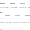
- FIG. 4 is an illustration of a first signal and a first further signal together with the binary signal used for generation
- FIG. 5 is an illustration of a first signal and a first further signal together with the binary signal used for generation
- FIG. 6 is an illustration for determining a virtual frequency switching time
- FIG. 7 is an illustration of a signal round-trip time measurement
- FIG. 8 is an illustration of two signal round-trip time measurements
- FIG. 9 is an illustration of a sequence of several following first and following second signals for measuring the signal round-trip time.
- FIG. 1 shows two PLLs, which can emit their output signal via an amplifier to an antenna by means of a downstream switch. Only the signal of one PLL may be forwarded. Each of the PLLs can be set to different frequencies.
- a control system is shown, which is configured to evaluate the phases of the signals of the PLLs and calculate a switching time, at which the switch is being activated and resulting in a continuous phase-coherent signal.
- switching elements designed as semiconductors are used as switches, e.g., transistors or MOSFETs.
- FIG. 2 shows phase measurements on a first signal (S 1 ) (three marks on the left) and on three first further signals (S 1 w . 1 -S 1 w . 3 ) (next three marks) with different frequencies (f 1 , f 1 w . 1 -f 1 w . 1 -f 1 w . 3 ) received at a second object after being emitted from a first object, plotted against time, including extrapolations of the measured values based on interpolation, as straight lines.
- intersection points of the straight lines are each indicated by a vertical dashed line, which marks the first virtual frequency switching time (dashed line on the left), and further virtual frequency switching times (following dashed lines), which can each be determined in this way assuming phase-coherent switching (first and further phase differences each equal zero).
- FIG. 3 shows phase measurements on a first signal (left three marks) and on a first further signal (three marks on the right) plotted against time, as well as extrapolations of the measured values based on interpolation, as straight lines.
- the vertical dashed line indicates the first virtual frequency switching point, which may be determined in this way assuming toggling with a first phase difference represented by the double arrow (first phase difference ⁇ >0).
- FIG. 4 shows a binary signal on top, and a frequency shift keyed signal below by coherent switching between two PLLs tuned to different frequencies. Below this, the resulting signal is characterized as a repeating sequence of first and further first signals.
- the switch between the first further frequency to the first frequency is also advantageously evaluated, e.g., by performing the method on the assumption that the first further signal represents the first signal and the first signal following this represents the first further signal.
- FIG. 5 shows an illustration similar to FIG. 4 , with the difference that each switching (frequency shift keying) requires a minor time gap and a predetermined phase jump.
- FIG. 6 shows an alternative determination of a first virtual frequency switching time with phase-coherent switching.
- the upper line shows samplings at the first signal (left seven marks) and samplings at the first further signal (seven marks on the right) shown over time from left to right.
- the variation over time of the first signal (left) and the first further signal (right) is illustrated as solid lines. No signal is present or no signal is received in the area of the continued dashed line.
- the dashed lines can be determined by extrapolating by an equalization calculation on the sampling d values of the first signal or the first further signal.
- the first virtual frequency switching time indicated by a vertical dashed line, may be determined. Note that not every contact of the dashed lines represents a virtual frequency switching time, since the phase position must be identical.
- FIG. 7 again shows the phase plotted against time.
- Two temporal axes can be seen, one for the time period at the first object, t O1 , and one for the second at the second object, t O2 ; the signals emitted from the first object and received at the second object (first signal and first further signal), at which the second object takes phase measurements (dashed measuring points), are shown on the left.
- the first object has switched or changed the frequency without a phase jump at the time t U1.1 . From the measuring points of the phase measurements of the second object, the corresponding virtual frequency switching time t 1.1 can be determined. According to the above explanations, this is also feasible with other types of switching, e.g., interruption of the emission and/or a phase jump.
- the signal emitted from the second object is received at the first object, as are the second signal and the second further signal.
- the second object has changed frequency in a phase coherent manner at the time t U2.1 .
- the first object takes phase measurements on the signals (measuring points on the right in the figure). From this, the corresponding second virtual frequency switching time can be determined.
- the signal round-trip time can be calculated by subtracting the second interval from the first. This will now be explained again in more detail with reference to the following drawings.
- FIG. 8 shows the scenario depicted in FIG. 7 on the left.
- the slanted dashed arrows illustrate the radio transmission, first from the first object to the second object, and then from the second object to the first object.
- no pulse is emitted, however, the toggling is situated there, such that if the frequency change along with an interruption at this time, no signal whatsoever is emitted.
- the arrows between the temporal axes are thus more apt to illustrate the transmission than represent an actual signal.
- the first and second time differences explained above are indicated as time intervals, each with a double arrow. it can be seen that their difference coincides with the sum of the signal runtimes.
- FIG. 9 shows in the notation from FIG. 8 , an implementation with a first signal and three first further signals and a second signal and three second further signals, in which three first switching times or switching times t U1.n , three first virtual frequency switching times t 1.n , three second switching times or toggling times t U2.n and three second virtual frequency switching times t 2.n are present. It can be seen that the time interval between the first virtual frequency switching time and the first second frequency-toggling time (lowest double arrow in FIG. 9 ) is roughly the same as the time interval between the second virtual frequency switching time and the second frequency-toggling time (third double arrow from the bottom in FIG.
- Three signal round-trip times can now be determined directly from these measurements. However, by calculating further time intervals between the respective points in time drawn on a time line, further signal round-trip times can also be determined.
- the signal runtime may be determined by way of halving.
- the second object can determine the exact position of the time t U1.1 on the first object on its second-object clock by subtracting the signal runtime (half the round-trip time) from the time t 1.1 .
- the clock on the second object can now also be synchronized with the first object clock with great accuracy.
- a time alignment may be done, which is far more accurate than was previously feasible with the prior-art methods
Landscapes
- Engineering & Computer Science (AREA)
- Radar, Positioning & Navigation (AREA)
- Remote Sensing (AREA)
- Physics & Mathematics (AREA)
- General Physics & Mathematics (AREA)
- Radar Systems Or Details Thereof (AREA)
- Computer Networks & Wireless Communication (AREA)
Applications Claiming Priority (6)
| Application Number | Priority Date | Filing Date | Title |
|---|---|---|---|
| DE202019100829 | 2019-02-13 | ||
| DE202019100829.6 | 2019-02-13 | ||
| EPPCT/EP2019/058153 | 2019-04-01 | ||
| WOPCT/EP2019/058153 | 2019-04-01 | ||
| EP2019058153 | 2019-04-01 | ||
| PCT/EP2020/053410 WO2020165134A1 (de) | 2019-02-13 | 2020-02-11 | Laufzeitmessung basierend auf frequenzumschaltung |
Publications (2)
| Publication Number | Publication Date |
|---|---|
| US20220128676A1 US20220128676A1 (en) | 2022-04-28 |
| US11899092B2 true US11899092B2 (en) | 2024-02-13 |
Family
ID=69423343
Family Applications (1)
| Application Number | Title | Priority Date | Filing Date |
|---|---|---|---|
| US17/430,376 Active 2040-12-09 US11899092B2 (en) | 2019-02-13 | 2020-02-11 | Travel time measurement based on frequency switching |
Country Status (4)
| Country | Link |
|---|---|
| US (1) | US11899092B2 (de) |
| EP (2) | EP3714287B1 (de) |
| CN (1) | CN113424074B (de) |
| WO (1) | WO2020165134A1 (de) |
Families Citing this family (3)
| Publication number | Priority date | Publication date | Assignee | Title |
|---|---|---|---|---|
| EP4062188A1 (de) * | 2020-11-04 | 2022-09-28 | Lambda: 4 Entwicklungen GmbH | Verfahren zur bestimmung von entfernungen zwischen mehreren objekten |
| US20230408664A1 (en) * | 2020-11-04 | 2023-12-21 | Lambda:4 Entwicklungen Gmbh | Method for a one-sided radio-based distance measurement |
| US20230408666A1 (en) * | 2020-11-04 | 2023-12-21 | Lambda:4 Entwicklungen Gmbh | Method for one-sided radio-based distance measurement |
Citations (11)
| Publication number | Priority date | Publication date | Assignee | Title |
|---|---|---|---|---|
| US4087816A (en) | 1975-12-19 | 1978-05-02 | Canadian Patents & Development Limited | VLF radio position location system |
| US4283726A (en) | 1978-09-05 | 1981-08-11 | Lewis C. Spence | Dual frequency distance measuring system |
| US6240152B1 (en) | 1998-08-18 | 2001-05-29 | Sun Microsystems, Inc. | Apparatus and method for switching frequency modes in a phase locked loop system |
| US6868073B1 (en) | 2000-06-06 | 2005-03-15 | Battelle Memorial Institute K1-53 | Distance/ranging by determination of RF phase delta |
| EP2204669A1 (de) | 2008-12-30 | 2010-07-07 | Atmel Automotive GmbH | System, Verfahren und Schaltung zur Entfernungsmessung zwischen zwei Knoten eines Funknetzes |
| US20100207820A1 (en) | 2006-09-05 | 2010-08-19 | Radio Communication Systems Ltd. | Distance measuring device |
| US9014239B2 (en) | 2011-01-12 | 2015-04-21 | Atmel Corporation | Transmission-reception device of a node of a radio network |
| WO2018059782A1 (de) | 2016-09-30 | 2018-04-05 | Fraunhofer-Gesellschaft zur Förderung der angewandten Forschung e.V. | Telegram splitting basierte lokalisierung |
| US20220095262A1 (en) * | 2019-03-07 | 2022-03-24 | Koninklijke Kpn N.V. | Phase-based distance determination for wireless networks |
| US11290844B2 (en) * | 2020-02-14 | 2022-03-29 | Kabushiki Kaisha Toshiba | Distance measurement apparatus and distance measurement method |
| US20230030936A1 (en) * | 2021-07-29 | 2023-02-02 | Spearix Technologies, Inc. | Accurate Clock Synchronization and Location Detection in Time-Sensitive Wireless Networks |
Family Cites Families (19)
| Publication number | Priority date | Publication date | Assignee | Title |
|---|---|---|---|---|
| CA1271546A (en) * | 1985-10-08 | 1990-07-10 | Accutrak Systems Limited | Vehicle guidance and ranging system |
| US5497126A (en) * | 1993-11-09 | 1996-03-05 | Motorola, Inc. | Phase synchronization circuit and method therefor for a phase locked loop |
| JPH07234272A (ja) * | 1994-02-23 | 1995-09-05 | Meisei Electric Co Ltd | 自動同期1ウエイ測距方式及び装置 |
| US5748891A (en) * | 1994-07-22 | 1998-05-05 | Aether Wire & Location | Spread spectrum localizers |
| CN1134123C (zh) * | 1995-09-20 | 2004-01-07 | 英国国防部 | 探测一个未知信号源的位置 |
| US6243587B1 (en) * | 1997-12-10 | 2001-06-05 | Ericsson Inc. | Method and system for determining position of a mobile transmitter |
| US6731908B2 (en) * | 2001-01-16 | 2004-05-04 | Bluesoft, Inc. | Distance measurement using half-duplex RF techniques |
| CN100403672C (zh) * | 2002-08-26 | 2008-07-16 | 联发科技股份有限公司 | 使用双模式相位频率检测器的锁相环 |
| EP1672382A1 (de) * | 2004-12-18 | 2006-06-21 | Leica Geosystems AG | Einkanal-Heterodyn -Distanzmessverfahren |
| DE602006012795D1 (de) * | 2006-01-19 | 2010-04-22 | Thales Sa | Vorrichtung zur Regelung der relativen Positionen von einer Gruppe in Formation fliegender Raumschiffe durch Analyse von Zweifrequenzsignalen |
| DE102007043649B4 (de) * | 2007-09-13 | 2012-03-22 | Siemens Ag | Verfahren zur Erhöhung der Ortungsgenauigkeit unsynchronisierter Funkteilnehmer |
| WO2009119599A1 (ja) * | 2008-03-27 | 2009-10-01 | 日本電気株式会社 | クロック同期システム、ノード、クロック同期方法及びプログラム |
| DE102009060592B4 (de) * | 2008-12-30 | 2012-06-06 | Atmel Automotive Gmbh | Schaltung und Verfahren zur Entfernungsmessung zwischen zwei Knoten eines Funknetzes |
| DE102009060505B4 (de) * | 2008-12-30 | 2011-09-01 | Atmel Automotive Gmbh | Schaltung, System und Verfahren zur Kommunikation zwischen zwei Knoten eines Funknetzes |
| JP5730094B2 (ja) * | 2011-03-28 | 2015-06-03 | 株式会社トプコン | 光波距離計 |
| EP2814177B1 (de) * | 2013-06-10 | 2015-09-23 | Asahi Kasei Microdevices Corporation | Phasenregelkreisvorrichtung mit Synchronisierungsmitteln |
| CN104579101B (zh) * | 2014-12-02 | 2017-10-13 | 苏州汇川技术有限公司 | 高压变频器变频切换至工频的控制系统以及控制方法 |
| JP6544047B2 (ja) * | 2015-05-29 | 2019-07-17 | セイコーエプソン株式会社 | 基準信号発生装置、電子機器、データ通信装置および地上デジタル通信網 |
| CN106788105B (zh) * | 2016-12-30 | 2019-04-23 | 苏州英威腾电力电子有限公司 | 一种变频切换工频的方法、变频器及电力切换系统 |
-
2020
- 2020-02-11 EP EP20703256.6A patent/EP3714287B1/de active Active
- 2020-02-11 CN CN202080014187.4A patent/CN113424074B/zh active Active
- 2020-02-11 WO PCT/EP2020/053410 patent/WO2020165134A1/de unknown
- 2020-02-11 US US17/430,376 patent/US11899092B2/en active Active
- 2020-02-11 EP EP21181902.4A patent/EP3913396A1/de active Pending
Patent Citations (11)
| Publication number | Priority date | Publication date | Assignee | Title |
|---|---|---|---|---|
| US4087816A (en) | 1975-12-19 | 1978-05-02 | Canadian Patents & Development Limited | VLF radio position location system |
| US4283726A (en) | 1978-09-05 | 1981-08-11 | Lewis C. Spence | Dual frequency distance measuring system |
| US6240152B1 (en) | 1998-08-18 | 2001-05-29 | Sun Microsystems, Inc. | Apparatus and method for switching frequency modes in a phase locked loop system |
| US6868073B1 (en) | 2000-06-06 | 2005-03-15 | Battelle Memorial Institute K1-53 | Distance/ranging by determination of RF phase delta |
| US20100207820A1 (en) | 2006-09-05 | 2010-08-19 | Radio Communication Systems Ltd. | Distance measuring device |
| EP2204669A1 (de) | 2008-12-30 | 2010-07-07 | Atmel Automotive GmbH | System, Verfahren und Schaltung zur Entfernungsmessung zwischen zwei Knoten eines Funknetzes |
| US9014239B2 (en) | 2011-01-12 | 2015-04-21 | Atmel Corporation | Transmission-reception device of a node of a radio network |
| WO2018059782A1 (de) | 2016-09-30 | 2018-04-05 | Fraunhofer-Gesellschaft zur Förderung der angewandten Forschung e.V. | Telegram splitting basierte lokalisierung |
| US20220095262A1 (en) * | 2019-03-07 | 2022-03-24 | Koninklijke Kpn N.V. | Phase-based distance determination for wireless networks |
| US11290844B2 (en) * | 2020-02-14 | 2022-03-29 | Kabushiki Kaisha Toshiba | Distance measurement apparatus and distance measurement method |
| US20230030936A1 (en) * | 2021-07-29 | 2023-02-02 | Spearix Technologies, Inc. | Accurate Clock Synchronization and Location Detection in Time-Sensitive Wireless Networks |
Non-Patent Citations (2)
| Title |
|---|
| A 10μs Fast Switching PLL Synthesizer for a GSM/EDGE Base-Station; ISSCC 2001/Session 10/Cellular Systems and Building Blocks/10.6; 2004 IEEE International Solid-State Circuits Conference; 0-7803-8267-6/04; 2004. |
| ADF4196 Fractional-N PLLs Frequency Synthesizers; www.mouser.in/new/Analog-Devices/ad-ad4196-synthesizers/; Feb. 5, 2019. |
Also Published As
| Publication number | Publication date |
|---|---|
| WO2020165134A1 (de) | 2020-08-20 |
| EP3714287A1 (de) | 2020-09-30 |
| EP3913396A1 (de) | 2021-11-24 |
| CN113424074B (zh) | 2024-05-24 |
| EP3714287B1 (de) | 2021-09-22 |
| US20220128676A1 (en) | 2022-04-28 |
| CN113424074A (zh) | 2021-09-21 |
Similar Documents
| Publication | Publication Date | Title |
|---|---|---|
| US11899092B2 (en) | Travel time measurement based on frequency switching | |
| US10416301B2 (en) | Distance measurement between two nodes of a radio network | |
| Zand et al. | A high-accuracy phase-based ranging solution with Bluetooth Low Energy (BLE) | |
| EP2710398B1 (de) | Verfahren zur bestimmung des standortes eines empfängers | |
| US8965301B2 (en) | Distance measurement between two nodes of a radio network | |
| US8063826B2 (en) | Wireless time reference system and method | |
| US10466350B2 (en) | Transmitter-receiver circuit and method for distance measurement between a first node and a second node of a radio network | |
| KR102278482B1 (ko) | 텔레그램 분할 기반 위치 파악 | |
| TWI546556B (zh) | 用於定位射頻標籤之方法 | |
| EP3533168B1 (de) | Empfänger und verfahren zur bereitstellung einer phasenkohärenz für frequenzsprungmehrtonsignale | |
| JP2007071819A (ja) | 受信装置および周波数偏差計測ユニットおよび測位測距システム | |
| Von Zengen et al. | No-Cost distance estimation using standard WSN radios | |
| US10656258B2 (en) | Measurement accuracy classifier for high-resolution ranging | |
| US20210215812A1 (en) | Electronic device and method for low power rf ranging | |
| WO2008057667A2 (en) | Method for measuring time of arrival of signals in a communications network | |
| CN112630803A (zh) | 定位系统和方法 | |
| JP4459951B2 (ja) | 距離推定 | |
| US8515454B2 (en) | Method of determining the location of a node in a distributed wireless sensor and actuator network | |
| US20230384410A1 (en) | Method for determining a distance between two objects with the involvement of a third object | |
| Zandian et al. | Implementation challenges of synchronisation of UWB nodes in TDoA structures | |
| US11555932B2 (en) | Round trip phase extended range | |
| EP0641447A1 (de) | Funkentfernungsmessgerät | |
| US11668785B2 (en) | Method for locating a connected object by phase differences of arrival in an LPWA network | |
| US11317310B2 (en) | Method for radio measuring applications | |
| Barrau et al. | New technique to resolve carrier-phase cycle ambiguity for narrowband low-power systems |
Legal Events
| Date | Code | Title | Description |
|---|---|---|---|
| AS | Assignment |
Owner name: LAMBDA:4 ENTWICKLUNGEN GMBH, GERMANY Free format text: ASSIGNMENT OF ASSIGNORS INTEREST;ASSIGNOR:REIMANN, RONNE;REEL/FRAME:057159/0066 Effective date: 20210712 |
|
| FEPP | Fee payment procedure |
Free format text: ENTITY STATUS SET TO UNDISCOUNTED (ORIGINAL EVENT CODE: BIG.); ENTITY STATUS OF PATENT OWNER: SMALL ENTITY |
|
| FEPP | Fee payment procedure |
Free format text: ENTITY STATUS SET TO SMALL (ORIGINAL EVENT CODE: SMAL); ENTITY STATUS OF PATENT OWNER: SMALL ENTITY |
|
| STPP | Information on status: patent application and granting procedure in general |
Free format text: DOCKETED NEW CASE - READY FOR EXAMINATION |
|
| STPP | Information on status: patent application and granting procedure in general |
Free format text: NON FINAL ACTION MAILED |
|
| STPP | Information on status: patent application and granting procedure in general |
Free format text: RESPONSE TO NON-FINAL OFFICE ACTION ENTERED AND FORWARDED TO EXAMINER |
|
| STPP | Information on status: patent application and granting procedure in general |
Free format text: NOTICE OF ALLOWANCE MAILED -- APPLICATION RECEIVED IN OFFICE OF PUBLICATIONS |
|
| STPP | Information on status: patent application and granting procedure in general |
Free format text: PUBLICATIONS -- ISSUE FEE PAYMENT RECEIVED |
|
| STPP | Information on status: patent application and granting procedure in general |
Free format text: PUBLICATIONS -- ISSUE FEE PAYMENT VERIFIED |
|
| STCF | Information on status: patent grant |
Free format text: PATENTED CASE |