US11887871B2 - Substrate processing apparatus and substrate processing method - Google Patents
Substrate processing apparatus and substrate processing method Download PDFInfo
- Publication number
- US11887871B2 US11887871B2 US16/942,018 US202016942018A US11887871B2 US 11887871 B2 US11887871 B2 US 11887871B2 US 202016942018 A US202016942018 A US 202016942018A US 11887871 B2 US11887871 B2 US 11887871B2
- Authority
- US
- United States
- Prior art keywords
- processing
- liquid
- processing liquid
- tub
- heating
- Prior art date
- Legal status (The legal status is an assumption and is not a legal conclusion. Google has not performed a legal analysis and makes no representation as to the accuracy of the status listed.)
- Active, expires
Links
Images


Classifications
-
- H—ELECTRICITY
- H01—ELECTRIC ELEMENTS
- H01L—SEMICONDUCTOR DEVICES NOT COVERED BY CLASS H10
- H01L21/00—Processes or apparatus adapted for the manufacture or treatment of semiconductor or solid state devices or of parts thereof
- H01L21/67—Apparatus specially adapted for handling semiconductor or electric solid state devices during manufacture or treatment thereof; Apparatus specially adapted for handling wafers during manufacture or treatment of semiconductor or electric solid state devices or components ; Apparatus not specifically provided for elsewhere
- H01L21/67005—Apparatus not specifically provided for elsewhere
- H01L21/67011—Apparatus for manufacture or treatment
- H01L21/67017—Apparatus for fluid treatment
- H01L21/67063—Apparatus for fluid treatment for etching
- H01L21/67075—Apparatus for fluid treatment for etching for wet etching
- H01L21/67086—Apparatus for fluid treatment for etching for wet etching with the semiconductor substrates being dipped in baths or vessels
-
- H10P72/0434—
-
- H10P72/0426—
-
- H—ELECTRICITY
- H01—ELECTRIC ELEMENTS
- H01L—SEMICONDUCTOR DEVICES NOT COVERED BY CLASS H10
- H01L21/00—Processes or apparatus adapted for the manufacture or treatment of semiconductor or solid state devices or of parts thereof
- H01L21/67—Apparatus specially adapted for handling semiconductor or electric solid state devices during manufacture or treatment thereof; Apparatus specially adapted for handling wafers during manufacture or treatment of semiconductor or electric solid state devices or components ; Apparatus not specifically provided for elsewhere
- H01L21/67005—Apparatus not specifically provided for elsewhere
- H01L21/67011—Apparatus for manufacture or treatment
- H01L21/67017—Apparatus for fluid treatment
- H01L21/67028—Apparatus for fluid treatment for cleaning followed by drying, rinsing, stripping, blasting or the like
- H01L21/6704—Apparatus for fluid treatment for cleaning followed by drying, rinsing, stripping, blasting or the like for wet cleaning or washing
- H01L21/67057—Apparatus for fluid treatment for cleaning followed by drying, rinsing, stripping, blasting or the like for wet cleaning or washing with the semiconductor substrates being dipped in baths or vessels
-
- H—ELECTRICITY
- H01—ELECTRIC ELEMENTS
- H01L—SEMICONDUCTOR DEVICES NOT COVERED BY CLASS H10
- H01L21/00—Processes or apparatus adapted for the manufacture or treatment of semiconductor or solid state devices or of parts thereof
- H01L21/67—Apparatus specially adapted for handling semiconductor or electric solid state devices during manufacture or treatment thereof; Apparatus specially adapted for handling wafers during manufacture or treatment of semiconductor or electric solid state devices or components ; Apparatus not specifically provided for elsewhere
- H01L21/67005—Apparatus not specifically provided for elsewhere
- H01L21/67242—Apparatus for monitoring, sorting or marking
- H01L21/67248—Temperature monitoring
-
- H—ELECTRICITY
- H01—ELECTRIC ELEMENTS
- H01L—SEMICONDUCTOR DEVICES NOT COVERED BY CLASS H10
- H01L22/00—Testing or measuring during manufacture or treatment; Reliability measurements, i.e. testing of parts without further processing to modify the parts as such; Structural arrangements therefor
- H01L22/30—Structural arrangements specially adapted for testing or measuring during manufacture or treatment, or specially adapted for reliability measurements
-
- H10P14/69215—
-
- H10P14/69433—
-
- H10P50/283—
-
- H10P50/642—
-
- H10P72/0416—
-
- H10P72/0602—
-
- H10P72/0604—
-
- H10P74/27—
Definitions
- the various aspects and embodiments described herein pertain generally to a substrate processing apparatus and a substrate processing method.
- a substrate processing apparatus described in Patent Document 1 includes a processing tub, a circulation line, a pump, a heater, at least two temperature sensors, and a controller.
- the processing tub stores therein a processing liquid in which a substrate is to be immersed.
- the circulation line returns the processing liquid overflown from the processing tub back into the processing tub.
- the pump, the heater and one of the two temperature sensors are provided on the circulation line.
- the other temperature sensor is provided within a water tank within the processing tub.
- the controller controls a heating amount of the heater based on detection temperatures of the at least two temperature sensors.
- a substrate processing apparatus includes a processing tub configured to store therein a processing liquid in which multiple substrates are to be immersed; multiple liquid supplies each of which includes a supply line through which the processing liquid is supplied to an inside of a water tank of the processing tub and a heating device configured to heat the processing liquid at a portion of the supply line; and multiple in-tank temperature sensors configured to measure a temperature of the processing liquid at multiple positions within the water tank of the processing tub.
- FIG. 1 is a front cross sectional view illustrating a substrate processing apparatus according to an exemplary embodiment
- FIG. 2 A is a side cross sectional view illustrating a layout of a plurality of liquid supplies and a plurality of in-tank temperature sensors according to the exemplary embodiment
- FIG. 2 B is a plan view illustrating a layout of horizontal pipes of each of the plurality of liquid supplies shown in FIG. 2 A ;
- FIG. 3 is a functional block diagram illustrating constituent components of a controller according to the exemplary embodiment
- FIG. 4 is a side cross sectional view illustrating a layout of a plurality of liquid supplies and a plurality of in-tank temperature sensors according to a first modification example
- FIG. 5 is a functional block diagram illustrating constituting components of a controller according to the first modification example
- FIG. 6 A is a side cross sectional view illustrating a layout of a plurality of liquid supplies and a plurality of in-tank temperature sensors according to a second modification example
- FIG. 6 B is a plan view illustrating a layout of the plurality of liquid supplies shown in FIG. 6 A ;
- FIG. 7 is a side cross sectional view illustrating a layout of a plurality of liquid supplies according to a third modification example.
- FIG. 8 is a side cross sectional view illustrating a layout of a plurality of liquid supplies according to a fourth modification example.
- the X-axis direction, the Y-axis direction and the Z-axis direction are orthogonal to each other, and the X-axis and Y-axis directions are horizontal directions whereas the Z-axis direction is a vertical direction.
- FIG. 1 is a front cross sectional view illustrating a substrate processing apparatus according to an exemplary embodiment.
- the substrate processing apparatus 1 is of a batch type configured to process a plurality of substrates 2 by immersing them in a processing liquid 3 .
- the substrate processing apparatus 1 includes a processing tub 5 .
- the processing tub 5 stores the processing liquid 3 therein, and the substrates 2 are processing by being immersed in the processing liquid 3 within a water tank of the processing tub 5 .
- Each substrate 2 includes, by way of example, a silicon wafer, a silicon oxide film and a silicon nitride film.
- the silicon oxide film and the silicon nitride film are alternately stacked on top of each other repeatedly, thus forming a stacked film.
- the stacked film has an opening formed through it in a thickness direction thereof.
- the processing liquid 3 is, for example, an etching liquid for use in etching the substrates 2 .
- the processing liquid 3 may be, by way of non-limiting example, a phosphoric acid aqueous solution and is maintained in a boiling state within the water tank of the processing tub 5 . This processing liquid enters the opening of the stacked film and selectively etches and removes the silicon nitride film among the silicon oxide film and the silicon nitride film.
- the processing tub 5 is, for example, a dual tub, and includes an inner tub 51 configured to store the processing liquid 3 therein and an outer tub 52 configured to collect the processing liquid 3 overflown from the inner tub 51 .
- the outer tub 52 surrounds an upper portion of the inner tub 51 .
- the inner tub 51 is located at an outside of the outer tub 52 in FIG. 1 , it may be located inside the outer tub 52 . That is, the outer tub 52 may accommodate the inner tub 51 therein.
- the substrates 2 are immersed in and processed by the processing liquid 3 within the water tank of the inner tub 51 .
- a cover 53 may be disposed above the inner tub 51 to keep the processing liquid 3 warm while suppressing scattering of the processing liquid 3 .
- the substrate processing apparatus 1 is equipped with a liquid supply 6 configured to supply the processing liquid 3 into the water tank of the processing tub 5 .
- the liquid supply 6 has a supply line 61 through which the processing liquid 3 flows.
- the supply line 61 may be a flow path through which the processing liquid 3 supplied from an outside of the processing tub 5 is replenished into the processing tub 5 .
- the supply line 61 is a circulation path through which the processing liquid 3 overflown from the processing tub 5 is returned back into the processing tub 5 .
- the circulation path is configured to return the processing liquid 3 extracted from the outer tub 52 into the inner tub 51 . Accordingly, the processing liquid 3 can be reused.
- the liquid supply 6 is equipped with a liquid feeding device 62 , a heating device 63 , a heating temperature sensor 64 and a flowmeter 65 at a portion of the supply line 61 .
- the liquid feeding device 62 may be, by way of example, but not limitation, a pump and is configured to send the processing liquid 3 .
- the heating device 63 is, for example, an electric heater and configured to heat the processing liquid 3 .
- the heating temperature sensor 64 is configured to measure a temperature of the processing liquid 3 at a downstream of the heating device 63 . An output variation of the heating device 63 is immediately reflected on a measurement value of the heating temperature sensor 64 .
- the heating temperature sensor 64 may be disposed near the heating device 63 to improve responsiveness to the output variation of the heating device 63 .
- the flowmeter 65 is configured to measure a flow rate of the processing liquid 3 at a downstream of the liquid feeding device 62 . An output variation of the liquid feeding device 62 is immediately reflected on a measurement value of the flowmeter 65
- the liquid supply 6 has, at a leading end of the supply line 61 , a nozzle 66 configured to discharge the processing liquid 3 into the water tank of the processing tub 5 .
- the nozzle 66 discharges the processing liquid 3 into, for example, the water tank of the inner tub 51 .
- the nozzle 66 may discharge a mixed fluid of the processing liquid 3 and a gas.
- nozzles 66 A and 66 B shown in FIG. 2 A have a L-shape and include vertical pipes 69 A and 69 B and horizontal pipes 67 A and 67 B horizontally extending from lower ends of the vertical pipes 69 A and 69 B, respectively.
- a horizontal pipe 67 is a hollow rod extending under the substrates 2 in an arrangement direction of the substrates 2 (X-axis direction), and the number of the horizontal pipe 67 is plural and these horizontal pipes 67 are arranged at a regular distance therebetween in the Y-axis direction.
- Each of the horizontal pipes 67 has a multiple number of discharge openings 68 arranged at a regular distance therebetween in a lengthwise direction of the horizontal pipe 67 , and the processing liquid 3 is discharged directly upwards from each of these multiple discharge openings 68 . Accordingly, a curtain-shaped up-flow is formed within the water tank of the inner tub 51 .
- the substrate processing apparatus 1 is equipped with a substrate holder 7 configured to hold the plurality of substrates 2 .
- the substrate holder 7 includes a plurality of substrate holding rods 71 arranged at a regular distance therebetween in a circumferential direction to hold an edge of the substrate 2 ; and a non-illustrated connection plate connected to one ends of the individual holding rods 71 .
- Each of the plurality of holding rods 71 extends from the connection plate in the X-axis direction, that is, the arrangement direction of the substrates 2 , and has a multiple number of holding grooves arranged at a regular distance therebetween in a lengthwise direction of the holding rod 71 .
- the holding rods 71 hold the substrate 2 vertically in the holding grooves thereof.
- the substrate holder 7 is configured to be moved up and down between a standby position and a processing position.
- the standby position is a position where the plurality of substrates 2 are transferred to a non-illustrated transfer device, and is set to be located above the processing position.
- the processing position is a position where the substrates 2 are immersed in the processing liquid 3 .
- the substrate holder 7 receives, at the standby position, the substrates 2 to be processed from the transfer device, and is then moved down to the processing position. After a lapse of a predetermined time, the substrate holder 7 is raised back to the standby position and, at the standby position, the substrate holder 7 hands over the substrates 2 after being processed to the transfer device. Thereafter, the same operations are repeated.
- the cover 53 When the substrate holder 7 is moved up, the cover 53 is opened not to interfere with the substrate holder 7 . Meanwhile, when the substrate holder 7 is stopped at the standby position or the processing position, the cover 53 is closed. By closing the cover 53 , the processing liquid 3 can be kept warm and scattering of the processing liquid 3 can be suppressed.
- the controller 9 is, by way of example, a computer and includes, as depicted in FIG. 1 , a CPU (Central Processing Unit) 91 and a recording medium 92 such as a memory.
- the recording medium 92 stores therein a program for controlling various processings performed in the substrate processing apparatus 1 .
- the controller 9 controls an operation of the substrate processing apparatus 1 .
- the controller 9 is equipped with an input interface 93 and an output interface 94 .
- the controller 9 receives a signal from the outside through the input interface 93 and transmits a signal to the outside through the output interface 94 .
- This program is recorded in, for example, a computer-readable recording medium and is installed from this recording medium to the recording medium 92 of the controller 9 .
- the computer-readable recording medium may be, by way of example, but not limitation, a hard disk (HD), a flexible disk (FD), a compact disk (CD), a magnet optical disk (MO), a memory card, or the like.
- the program may be installed to the recording medium 92 of the controller 9 by being downloaded from a server through Internet.
- FIG. 2 A is a side cross sectional view illustrating a layout of a plurality of liquid supplies and a plurality of in-tank temperature sensors according to the exemplary embodiment.
- FIG. 2 B is a plan view illustrating a layout of horizontal pipes of the plurality of liquid supplies shown in FIG. 2 A .
- the substrate processing apparatus 1 includes a plurality of liquid supplies 6 A and 6 B, and each of the liquid supplies 6 A and 6 B includes a heating device 63 . Since an output of the heating device 63 of each of the liquid supplies 6 A and 6 B can be adjusted individually, a temperature distribution within the water tank of the inner tub 51 can be easily adjusted. Here, the temperature within the water tank of the inner tub 51 may be simply referred to as “in-tank temperature.”
- the processing liquid 3 After the temperature of the processing liquid 3 is adjusted in the liquid supplies 6 A and 6 B, the processing liquid 3 is supplied into the water tank of the inner tub 51 , and is then overflown from the inner tub 51 and collected into the outer tub 52 shown in FIG. 1 .
- the processing liquid 3 is mixed in a water tank of the outer tub 52 , so that the temperature of the processing liquid 3 is uniformed.
- the plurality of liquid supplies 6 A and 6 B may draw the processing liquid 3 from the same position of the outer tub 52 .
- a common line connecting a single outlet port of the outer tub 52 and the supply line 61 of each of the liquid supplies 6 A and 6 B is provided.
- the plurality of liquid supplies 6 A and 6 B may draw the processing liquid 3 from different positions of the outer tub 52 .
- the output of the heating device 63 of each of the liquid supplies 6 A and 6 B can be adjusted individually, so that a temperature distribution within the water tank can be adjusted easily.
- the substrate processing apparatus 1 is equipped with the plurality of in-tank temperature sensors 81 and measures the temperature of the processing liquid 3 at multiple positions within the water tank of the inner tub 51 .
- An in-tank temperature distribution can be calculated based on measurement values of these in-tank temperature sensors 81 .
- the in-tank temperature distribution is calculated as data in which a position of each of measurement points of the plurality of in-tank temperature sensors 81 and a measurement value at the measurement point are matched.
- the position of the measurement point is previously stored in the recording medium 92 and retrieved when used.
- the in-tank temperature distribution may further include data in which a position of a prediction point other than the measurement point and a prediction value at the prediction point are matched.
- the prediction point may be set to be located between the plurality of measurement points, or may be set to be a point other than the plurality of measurement points.
- the prediction value may be calculated by a general prediction method such as, but not limited to, interpolation or extrapolation.
- the in-tank temperature distribution is a distribution in a horizontal direction in the present exemplary embodiment, it may be a distribution in a vertical direction or a distribution in both of the horizontal direction and vertical direction. Further, the in-tank temperature distribution may be any of a one-dimensional distribution, a two-dimensional distribution and a three-dimensional distribution.
- the in-tank temperature distribution is calculated based on the measurement values of the plurality of in-tank temperature sensors 81 , it is possible to perform a manipulation of allowing an actual distribution to approach a target distribution. As a result, controllability of the in-tank temperature can be improved.
- the inside of the water tank of the inner tub 51 is divided into a first zone ZA and a second zone ZB, and the liquid supplies 6 A and 6 B are disposed to discharge the processing liquid 3 into the first zone ZA and the second zone ZB, respectively.
- a boundary between the adjacent zones ZA and ZB is an imaginary line.
- the inside of the water tank of the inner tub 51 is divided into the two zones ZA and ZB in an arrangement direction of the substrates 2 in FIG. 2 B , the inside of the water tank of the inner tub 51 may be divided into more than two zones.
- the plurality of zones ZA and ZB are divisions of the inside of the water tank of the inner tub 51 in, for example, the arrangement direction (X-axis direction) of the substrates 2 , as mentioned above.
- the plurality of substrates 2 can be sorted into a plurality of groups in the arrangement direction thereof, and a processing condition for the substrates 2 can be adjusted for each of the groups individually. In case that there is a processing fault in the substrates 2 of a certain group, the processing condition for the substrates 2 of this group can be changed. Therefore, a yield can be improved.
- the first liquid supply 6 A includes a first supply line 61 A, a first liquid feeding device 62 A, a first heating device 63 A, a first heating temperature sensor 64 A, a first flowmeter 65 A and a first nozzle 66 A.
- the first nozzle 66 A has a first horizontal pipe 67 A and first discharge openings 68 A. Further, the first nozzle 66 A also has a first vertical pipe 69 A.
- the horizontal pipe 67 A is a hollow rod extending in the arrangement direction (X-axis direction) of the substrates 2 .
- the horizontal pipe 67 A may be plural in number, and these horizontal pipes 67 A may be arranged at a regular distance therebetween in the Y-axis direction.
- the first discharge openings 68 A are provided in the first zone ZA without being provided in the second zone ZB. That is, the first liquid supply 6 A discharges the processing liquid 3 into the first zone ZA and does not discharge the processing liquid 3 into the second zone ZB.
- the second liquid supply 6 B includes a second supply line 61 B, a second liquid feeding device 62 B, a second heating device 63 B, a second heating temperature sensor 64 B, a second flowmeter 65 B, and a second nozzle 66 B.
- the second nozzle 66 B includes a second horizontal pipe 67 B and second discharge openings 68 B. Further, the second nozzle 66 B also has a second vertical pipe 69 B.
- the second horizontal pipe 67 B is a hollow rod extending in the arrangement direction (X-axis direction) of the substrates 2 .
- the second horizontal pipe 67 B may be plural in number, and these second horizontal pipes 67 B may be arranged at a regular distance therebetween in the Y-axis direction.
- the second discharge openings 68 B are provided in the second zone ZB without being provided in the first zone ZA. That is, the second liquid supply 6 B discharges the processing liquid 3 into the second zone ZB and does not discharge the processing liquid 3 into the first zone ZA.
- the plurality of liquid supplies 6 A and 6 B are disposed to discharge the processing liquid 3 into the zones ZA and ZB, respectively.
- the liquid supply (for example, the liquid supply 6 A) configured to discharge the processing liquid 3 into one zone (for example, the zone ZA) and the liquid supply (for example, the liquid supply 6 B) configured to discharge the processing liquid 3 into the other zone (for example, the zone ZB) need not to be completely same.
- the plurality of liquid supplies 6 A and 6 B are disposed not to discharge the processing liquid 3 into the plurality of zones ZA and ZB in duplicates.
- Each of the plurality of liquid supplies 6 A and 6 B discharges the processing liquid 3 into a different one of the plurality of zones ZA and ZB.
- Only one liquid supply (for example, the first liquid supply 6 A) discharges the processing liquid into the same zone (for example, the first zone ZA).
- the temperature of the processing liquid 3 can be adjusted for each of the zones ZA and ZB, so that a distribution of the in-tank temperature in the horizontal direction can be adjusted easily.
- One or more (one in FIG. 2 A ) in-tank temperature sensors 81 may be provided in each of the zones ZA and ZB. Accordingly, the distribution of the in-tank temperature in the horizontal direction can be measured. Further, it is also possible to adjust a heating temperature for the processing liquid 3 while monitoring the in-tank temperature of the processing liquid 3 for each of the zones ZA and ZB.
- FIG. 3 is a functional block diagram illustrating constituent components of the controller according to the exemplary embodiment.
- Each functional block shown in FIG. 3 is conceptual and need not necessarily be physically configured as shown in FIG. 3 .
- All or a part of the functional blocks may be functionally or physically dispersed or combined on a unit.
- All or a part of processing functions performed in the respective functional blocks may be implemented by a program performed in the CPU or implemented by hardware through a wired logic. The same applies to FIG. 5 to be described later.
- the controller 9 includes a heating temperature setting unit 95 and a heating controller 96 .
- the heating temperature setting unit 95 calculates the in-tank temperature distribution based on measurement values BPV of the plurality of in-tank temperature sensors 81 , and sets a target value HSV of the heating temperature of the processing liquid 3 by the heating device 63 based on the calculated distribution.
- the heating controller 96 controls the heating device 63 based on the target value HSV of the heating temperature.
- the heating temperature setting unit 95 calculates the in-tank temperature distribution based on the measurement values BPV of the plurality of in-tank temperature sensors 81 , and sets the target value HSV of the heating temperature of the processing liquid 3 by the heating device 63 based on a deviation between the actually calculated distribution and a target distribution.
- the target value HSV is calculated through an operation to render the deviation zero. In this operation, a PI operation, a PID operation, or the like may be used.
- the target distribution of the in-tank temperature is previously stored in the recording medium 92 and retrieved when used.
- the target distribution of the in-tank temperature may be a uniform distribution or a non-uniform distribution, and is appropriately updated based on an inspection result of the substrates 2 after being processed with the processing liquid 3 .
- the target distribution of the in-tank temperature is decided so that a processing fault of the substrates 2 can be reduced.
- the target distribution may be set to be a non-uniform distribution on purpose.
- the heating temperature setting unit 95 sets the target value HSV of the heating temperature of the heating device 63 based on the deviation of the actual distribution of the in-tank temperature and the target distribution thereof. Therefore, the actual distribution of the in-tank temperature is made to be coincident with the target distribution, so that the processing fault of the substrates 2 can be reduced.
- the heating temperature setting unit 95 may set the common target value HSV for all the liquid supplies 6 .
- the target value HSV may be set for each liquid supply 6 .
- the heating temperature setting unit 95 calculates a deviation between the measurement value BPV and the target value BSV thereof within the first zone ZA, and sets the target value HSV of the heating temperature of the processing liquid 3 by the first heating device 63 A based on the calculated deviation. Further, the heating temperature setting unit 95 calculates a deviation between the measurement value BPV and the target value BSV thereof within the second zone ZB, and sets the target value HSV of the heating temperature of the processing liquid 3 by the second heating device 63 B based on the calculated deviation. Since the heating temperature of the processing liquid 3 can be adjusted for each liquid supply 6 , the in-tank temperature distribution can be adjusted easily.
- the heating controller 96 is provided for each liquid supply 6 .
- the heating controller 96 controls the heating device 63 based on the deviation between the target value HSV of the heating temperature and the measurement value HPV of the heating temperature sensor 64 .
- the heating controller 96 controls an output of the heating device 63 to make zero the deviation between the target value HSV and the measurement value HPV.
- a PI operation, a PID operation, or the like may be used, for example.
- a time taken until an output variation of the heating device 63 is reflected on the measurement value HPV of the heating temperature is shorter than a time taken until the output variation of the heating device 63 is reflected on the measurement value BPV of the in-tank temperature. Accordingly, if the target value HSV of the heating temperature is corrected based on the deviation between the target value BSV of the in-tank temperature and the measurement value BPV thereof and if the output of the heating device 63 is controlled based on the deviation between the target value HSV of the heating temperature and the measurement value HPV thereof, responsiveness can be improved, so that the measurement value BPV of the in-tank temperature can be made equal to the target value BSV in a short time.
- the control shown in FIG. 3 is a so-called cascade control.
- a single feedback loop is composed of a master loop and a slave loop.
- the target value HSV of the heating temperature is corrected so that the deviation between the target temperature BSV and the measurement value BPV of the in-tank temperature becomes zero, and the output of the heating device 63 is controlled such that the deviation between the target value HSV and the measurement value HPV of the heating temperature becomes zero.
- FIG. 4 is a side cross sectional view illustrating a layout of the plurality of liquid supplies and a plurality of in-tank temperature sensors according to a first modification example. Since a plan view illustrating a layout of the horizontal pipes of the present modification example is the same as FIG. 2 B , illustration thereof is omitted.
- distinctive features of the present modification example from the above-described exemplary embodiment will be mainly discussed.
- a plurality of in-tank temperature sensors 81 D and 81 U are arranged at a regular distance therebetween in a vertical direction in a plurality of zones ZA and ZB, respectively.
- a distribution of an in-tank temperature in the vertical direction can be calculated for each of the plurality of zones ZA and ZB, so that it is possible to perform a manipulation of allowing the distribution of the in-tank temperature in the vertical direction to approach a target distribution.
- the distribution of the in-tank temperature in the vertical direction can be adjusted by controlling a flow rate of the processing liquid 3 which is discharged vertically upwards from the horizontal pipe 67 . Since the opening area of the discharge openings 68 is constant, a flow velocity of the processing liquid 3 becomes higher as the flow rate of the processing liquid 3 increases, and it is difficult for the processing liquid 3 to be deprived of heat until it reaches a liquid surface after being discharged from the discharge openings 68 . Thus, the larger the flow rate of the processing liquid 3 is, the smaller a difference of the in-tank temperature in the vertical direction is.
- the substrate processing apparatus 1 is equipped with the plurality of liquid supplies 6 , and each of the plurality of liquid supplies 6 has the liquid feeding device 62 . Since outputs of the liquid feeding devices 62 of the respective liquid supplies 6 can be adjusted individually, the distribution of the in-tank temperature in the vertical direction can be adjusted easily.
- the in-tank temperature sensors 81 D and 81 U are disposed above the horizontal pipe 67 , and the in-tank temperature sensor 81 D at a lower side is closer to the horizontal pipe 67 than the in-tank temperature sensor 81 U at an upper side. For the reason, a time taken for an output variation of the heating device 63 to be reflected on a measurement value HPV of the in-tank temperature sensor 81 D at the lower side is shorter than a time taken for the output variation of the heating device 63 to be reflected on a measurement value HPV of the in-tank temperature sensor 81 U at the upper side.
- the heating temperature setting unit 95 shown in FIG. 3 may acquire a measurement value BPV of the in-tank temperature from the in-tank temperature sensor 81 U at the upper side, it may acquire the measurement value BPV of the in-tank temperature from the in-tank temperature sensor 81 D at the lower side to improve responsiveness.
- the heating temperature setting unit 95 may calculate a deviation between the measurement value BPV of the in-tank temperature sensor 81 D at the lower side and a target value BSV thereof, and set a target value HSV of the heating temperature of the processing liquid 3 by the heating device 63 based on the calculated deviation.
- a flow rate setting unit 97 shown in FIG. 5 may acquire measurement values BPV of the in-tank temperature from both the in-tank temperature sensor 81 D at the lower side and the in-tank temperature sensor 81 U at the upper side.
- FIG. 5 is a functional block diagram illustrating constituent components of a controller according to the first modification example. Functional blocks shown in FIG. 5 may be used in combination with the functional blocks shown in FIG. 3 , or may be used alone.
- a controller 9 includes the flow rate setting unit 97 and a liquid feeding controller 98 .
- the flow rate setting unit 97 calculates a distribution of the in-tank temperature in the vertical direction based on the measurement values BPV of the plurality of in-tank temperature sensors 81 D and 81 U, and sets a target value FSV of the flow rate of the processing liquid 3 by the liquid feeding device 62 based on the calculated distribution of the in-tank temperature in the vertical direction.
- the distribution of the in-tank temperature in the vertical direction is represented by, for example, a temperature gradient (a temperature variation per a unit length) in the vertical direction.
- the liquid feeding controller 98 controls the liquid feeding device 62 based on the target value FSV of the flow rate.
- the flow rate setting unit 97 calculates the distribution of the in-tank temperature in the vertical direction based on the measurement values BPV of the plurality of in-tank temperature sensors 81 D and 81 U, and sets the target value FSV of the flow rate of the processing liquid 3 by the liquid feeding device 62 based on a deviation between the calculated distribution and a target distribution.
- the target value FSV is calculated through an operation to render the deviation zero. In this operation, a PI operation, a PID operation, or the like may be used.
- the flow rate setting unit 97 sets the target value FSV of the flow rate of the liquid feeding device 62 based on the deviation between the actual distribution of the in-tank temperature in the vertical direction and the target distribution thereof, the actual distribution of the in-tank temperature in the vertical direction can be made to be coincident with the target distribution, so that a processing fault of the substrates 2 can be reduced.
- the flow rate control unit 97 may set a common target value FSV for all the liquid supplies 6 , the target value FSV is set for each of the liquid supplies 6 individually in the present exemplary embodiment.
- the flow rate setting unit 97 calculates a deviation between a distribution in the vertical direction in the first zone ZA and a target distribution thereof, and sets a target value FSV of the flow rate of the processing liquid 3 by the first liquid feeding device 62 A based on this calculated deviation.
- the flow rate setting unit 97 calculates a deviation between a distribution in the vertical direction in the second zone ZB and a target distribution thereof, and sets a target value FSV of the flow rate of the processing liquid 3 by the second liquid feeding device 62 B based on this calculated deviation. Since the flow rate of the processing liquid 3 can be adjusted for each of the liquid supplies 6 individually, the distribution of the in-tank temperature in the vertical direction can be adjusted easily.
- the liquid feeding controller 98 is provided for each liquid supply 6 .
- the liquid feeding controller 98 controls the liquid feeding device 62 based on the deviation between the target value FSV of the flow rate and a measurement value FPV of the flowmeter 65 .
- the liquid feeding controller 98 controls an output of the liquid feeding device 62 to allow the deviation between the target value FSV and the measurement value FPV to become zero.
- a PI operation, a PID operation, or the like may be used for this calculation of the output of the liquid feeding device 62 .
- a time taken until an output variation of the liquid feeding device 62 is reflected on the measurement value FPV of the flow rate is shorter than a time taken until the output variation of the liquid feeding device 62 is reflected on the measurement value BPV of the in-tank temperature. Accordingly, if the target value FSV of the flow rate is corrected based on the deviation between the actual distribution of the in-tank temperature in the vertical direction and the target distribution thereof and, also, if the output of the liquid feeding device 62 is controlled based on the deviation of the target value FSV and the measurement value FPV of the flow rate, responsiveness can be bettered, so that the measurement value BPV of the in-tank temperature can be made to be coincide with the target value BSV in a short time.
- the control shown in FIG. 5 is a so-called cascade control.
- a single feedback loop is composed of a master loop and a slave loop.
- the target value FSV of the flow rate is corrected so that the deviation between the distribution of the in-tank temperature in the vertical direction and the target distribution thereof becomes zero, and the output of the liquid feeding device 62 is controlled such that the deviation between the target value FSV and the measurement value FPV of the flow rate becomes zero.
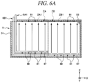
- FIG. 6 A is a side cross sectional view illustrating a layout of a plurality of liquid supplies and a plurality of in-tank temperature sensors according to a second modification example.
- FIG. 6 B is a plan view illustrating the layout of the plurality of liquid supplies shown in FIG. 6 A .
- in-tank temperature sensors 81 may be mounted to the horizontal pipe 67 of the liquid supply 6 .
- an additional member for supporting the in-tank temperature sensors 81 is not necessary.
- the horizontal pipe 67 is disposed under the substrates 2 which are immersed in the processing liquid 3 , the in-tank temperature sensors 81 can be arranged two-dimensionally within a horizontal plane under the substrates 2 . Therefore, a temperature distribution within the horizontal plane under the substrates 2 can be calculated.
- the in-tank temperature sensors 81 may be mounted to the cover 53 . In this case as well, an additional member for supporting the in-tank temperature sensors 81 is not required. Further, since the cover 53 is located above the substrates 2 which are immersed in the processing liquid 3 , the in-tank temperature sensors 81 can be arranged two-dimensionally within a horizontal plane above the substrates 2 . Therefore, a temperature distribution within the horizontal plane above the substrates 2 can be calculated.
- the in-tank temperature sensors 81 may be two-dimensionally arranged at both the horizontal pipe 67 and the cover 53 . In this case, since both the temperature distribution within the horizontal plane under the substrates 2 and the temperature distribution within the horizontal plane above the substrates 2 can be obtained, it is possible to calculate a three-dimensional temperature distribution within the water tank.
- the three-dimensional temperature distribution within the water tank can be calculated from measurement values of the in-tank temperature sensors 81 which are mounted to a member other than the horizontal pipe 67 and the cover 53 .
- the inside of the water tank of the inner tub 51 may be divided into a multiple number of zones ZA 1 , ZA 2 , ZA 3 , ZA 4 , ZB 1 , ZB 2 , ZB 3 and ZB 4 in the arrangement direction (X-axis direction) of the substrates 2 and a direction (Y-axis direction) orthogonal thereto. That is, the inside of the water tank of the inner tub 51 is divided into a plurality of zone groups ZA and ZB in the X-axis direction, and these zone groups ZA and ZB may be further divided into a multiple number of zones in the Y-axis direction.
- the zone group ZA is divided into the zones ZA 1 , ZA 2 , ZA 3 and ZA 4
- the zone group ZB is divided into the zones ZB 1 , ZB 2 , ZB 3 and ZB 4 .
- a plurality of liquid supplies 6 A 1 , 6 A 2 , 6 A 3 , 6 A 4 , 6 B 1 , 6 B 2 , 6 B 3 and 6 B 4 are disposed to discharge the processing liquid 3 into the zones ZA 1 , ZA 2 , ZA 3 , ZA 4 , ZB 1 , ZB 2 , ZB 3 and ZB 4 , respectively.
- the liquid supply (for example, the liquid supply 6 A 1 ) configured to discharge the processing liquid 3 into any one zone (for example, the zone ZA 1 ) and the liquid supply (for example, the liquid supply 6 A 2 ) configured to supply the processing liquid 3 into any one of the other zones (for example, the zone ZA 2 ) need not to be completely same.
- the inside of the water tank is divided into the plurality of zone groups ZA and ZB in the arrangement direction of the substrates 2 , and the different liquid supplies 6 discharge the processing liquid 3 into these zone groups ZA and ZB individually. Therefore, the substrates 2 can be sorted into multiple groups in the arrangement direction thereof, and a processing condition for the substrates 2 can be adjusted for each group. In case that there is a processing default of the substrates 2 of a certain group, the processing condition for the substrates 2 belonging to this group can be changed, so that a yield can be improved.
- the inside of the water tank (for example, the zone group ZA) is divided into the multiple zones ZA 1 , ZA 2 and ZA 3 in the direction orthogonal to the arrangement direction of the substrates 2 , and the different liquid supplies 6 discharge the processing liquid 3 into these zones. Therefore, a single sheet of substrate 2 can be divided into multiple regions in the direction orthogonal to the arrangement direction of the substrates 2 , and a processing condition for the substrate 2 can be set for each of the multiple regions individually. In case that there is a processing default in a certain region of this single sheet of substrate 2 , the processing condition for that region of the substrate 2 can be changed, so that the yield can be improved. This effect is also obtained when the inside of the water tank of the inner tub 51 is divided into the multiple zones only in the direction orthogonal to the arrangement direction of the substrates 2 .
- the number of division of the zones is larger than those in the above-described exemplary embodiment and the above-described first modification example.
- the present modification example is identical to the exemplary embodiment and the first modification example in that the in-tank temperature is controlled for zones individually. Therefore, the control shown in FIG. 3 or FIG. 5 is applicable to the present modification example as well.
- one or more in-tank temperature sensors 81 are disposed in each of the multiple zones ZA 1 , ZA 2 , ZA 3 , ZA 4 , ZB 1 , ZB 2 , ZB 3 and ZB 4 . Accordingly, a distribution of the in-tank temperature in the horizontal direction can be measured. Further, it is possible to adjust the heating temperature of the processing liquid 3 by the heating device 63 while monitoring the in-tank temperature of the processing liquid 3 for each of the zones ZA 1 , ZA 2 , ZA 3 , ZA 4 , ZB 1 , ZB 2 , ZB 3 and ZB 4 individually.
- one measurement value selected from these in-tank temperature sensors 81 may be used for the control of the heating temperature of the processing liquid 3 by the heating device 63 .
- the way to select the in-tank temperature sensors 81 is not particularly limited, one located closest to a place where a processing default of the substrates 2 occurs, and it may be appropriately updated based on an inspection result of the substrates 2 . Further, an average of measurement values of the individual in-tank temperature sensors 81 may be used for the control of the heating temperature of the processing liquid 3 by the heating device 63 .
- At least one set of in-tank temperature sensors 81 is disposed in each of the multiple zones ZA 1 , ZA 2 , ZA 3 , ZA 4 , ZB 1 , ZB 2 , ZB 3 and ZB 4 .
- the one set of in-tank temperature sensors 81 include a plurality of in-tank temperature sensors 81 arranged at a regular distance therebetween in the vertical direction. With this configuration, a distribution of the in-tank temperature in the vertical direction can be measured.
- a measurement value of one set selected from the multiple sets may be used for the control of the flow rate of the processing liquid 3 by the liquid feeding device 62 .
- the way to select the one set from the multiple sets is not particularly limited, one located closest to a place where a processing default of the substrates 2 occurs, and it may be appropriately updated based on an inspection result of the substrates 2 .
- an average of measurement values of the multiple sets may be used for the control of the flow rate of the processing liquid 3 by the liquid feeding device 62 .
- FIG. 7 is a side cross sectional view illustrating a layout of a plurality of liquid supplies according to a third modification example. Since a plan view illustrating a layout of horizontal pipes of the present modification example is the same as FIG. 2 B , illustration thereof is omitted. Further, the plan view illustrating the layout of the horizontal pipes of the present modification example may be the same as FIG. 6 B .
- distinctive features of the present modification example from the above-described exemplary embodiment will be mainly explained.
- the plurality of liquid supplies 6 A and 6 B are disposed so that the liquid supplies 6 A and 6 B do not discharge the processing liquid 3 into each of the plurality of zones ZA and ZB in duplicates.
- Each of the plurality of liquid supplies 6 A and 6 B discharges the processing liquid 3 into different one of the plurality of zones ZA and ZB. Only one liquid supply (for example, the first liquid supply 6 A) discharges the processing liquid into the one and the same zone (for example, the first zone ZA).
- both the first liquid supply 6 A and the second liquid supply 6 B discharge the processing liquid 3 into the first zone ZA in duplicates.
- the second liquid supply 6 B discharges the processing liquid 3 into the second zone ZB. Accordingly, the liquid supplies 6 A and 6 B which discharge the processing liquid 3 into the first zone ZA and the liquid supply 6 B which discharges the processing liquid 3 into the second zone ZB are not completely identical, that is, different.
- the different liquid supplies 6 discharge the processing liquid 3 into the different zones ZA and ZB. Therefore, the temperature of the processing liquid 3 can be adjusted for each of the zones ZA and ZB individually, so that the distribution of the in-tank temperature in the horizontal direction can be adjusted easily.
- the heating temperature setting unit 95 may first set a target value HSV of the heating temperature of the processing liquid 3 by the second heating device 63 B, and set a target value HSV of the heating temperature of the processing liquid 3 by the first heating device 63 A based on the target value HSV of the heating temperature of the processing liquid 3 by the second heating device 63 B.
- the flow rate setting unit 97 may first set a target value FSV of the flow rate of the processing liquid 3 by the second liquid feeding device 62 B, and set a target value FSV of the flow rate of the processing liquid 3 by the first liquid feeding device 62 A based on the target value FSV of the flow rate of the processing liquid 3 by the second liquid feeding device 62 B.
- the target value HSV of the heating temperature and the target value FSV of the flow rate can be set easily because the target values HSV and FSV can be set for each of the liquid supplies 6 A and 6 B independently.
- FIG. 8 is a side cross sectional view illustrating a layout of a plurality of liquid supplies according to a fourth modification example. Since a plan view illustrating a layout of horizontal pipes of the present modification example is the same as FIG. 2 B , illustration thereof is omitted. Further, the plan view illustrating the layout of the horizontal pipes of the present modification example may be the same as FIG. 6 B .
- distinctive features of the present modification example from the above-described exemplary embodiment will be mainly explained
- the substrate processing apparatus 1 further includes, in addition to the first liquid supply 6 A and the second liquid supply 6 B, a third liquid supply 6 C and a fourth liquid supply 6 D. Further, the substrate processing apparatus 1 may include only the third liquid supply 6 C and the fourth liquid supply 6 D.
- the inside (for example, a zone group ZA) of the water tank of the inner tub 51 is divided into multiple zones ZA 1 and ZA 2 in the vertical direction.
- the liquid supplies 6 C and 6 D are disposed to discharge the processing liquid 3 into the zones ZA 1 and ZA 2 arranged in the vertical direction, respectively.
- the third liquid supply 6 C includes a third supply line 61 C, a third liquid feeding device 62 C, a third heating device 63 C, a third heating temperature sensor 64 C, a third flowmeter 65 C, and a third nozzle 66 C.
- the third nozzle 66 C is equipped with a vertical pipe 69 C and third discharge openings 68 C.
- the third vertical pipe 69 C is provided at an end portion within the water tank of the inner tub 51 in the arrangement direction of the substrates 2 .
- the third vertical pipe 69 C is a hollow rod extending in the vertical direction.
- the third vertical pipe 69 C may be plural in number, and these vertical pipes 69 C may be arranged at a regular distance therebetween in the Y-axis direction.
- the processing liquid 3 is discharged from the third discharge openings 68 C in the arrangement direction of the substrates 2 .
- the third discharge openings 68 C are provided, between the two zones ZA 1 and ZA 2 arranged in the vertical direction, in the zone ZA 1 at a lower side, and not provided in the zone ZA 2 at an upper side. That is, the third liquid supply 6 C discharges the processing liquid 3 into the zone ZA 1 at the lower side and does not discharge the processing liquid 3 into the zone ZA 2 at the upper side.
- the fourth liquid supply 6 D includes a fourth supply line 61 D, a fourth liquid feeding device 62 D, a fourth heating device 63 D, a fourth heating temperature sensor 64 D, a fourth flowmeter 65 D, and a fourth nozzle 66 D.
- the fourth nozzle 66 D includes a fourth vertical pipe 69 D and fourth discharge openings 68 D.
- the fourth vertical pipe 69 D is provided at an end portion within the water tank of the inner tub 51 in the arrangement direction of the substrates 2 .
- the fourth vertical pipe 69 D is a hollow rod extending in the vertical direction.
- the fourth vertical pipe 69 D may be plural in number, and these vertical pipes 69 D may be arranged at a regular distance therebetween in the Y-axis direction.
- the processing liquid 3 is discharged from the fourth discharge openings 68 D in the arrangement direction of the substrates 2 .
- the fourth discharge openings 68 D are provided, between the two zones ZA 1 and ZA 2 arranged in the vertical direction, in the zone ZA 2 at the upper side, and not provided in the zone ZA 1 at the lower side. That is, the fourth liquid supply 6 D discharges the processing liquid 3 into the zone ZA 2 at the upper side and does not discharge the processing liquid 3 into the zone ZA 1 at the lower side.
- the temperature of the processing liquid 3 can be adjusted for each of the zones ZA 1 and ZA 2 individually, so that the distribution of the in-tank temperature in the vertical direction can be adjusted easily.
- One or more (one in FIG. 8 ) in-tank temperature sensors 81 are disposed in each of the multiple zones ZA 1 and ZA 2 arranged in the vertical direction. Accordingly, the distribution of the in-tank temperature in the vertical direction can be measured. Further, it is possible to adjust the heating temperature of the processing liquid 3 for each of the zones ZA 1 and ZA 2 individually while monitoring the in-tank temperature of the processing liquid 3 .
- the flow rate of the processing liquid 3 can be adjusted for each of the zones ZA 1 and ZA 2 individually, so that the distribution of the in-tank temperature in the horizontal direction can also be adjusted.
- processing liquid 3 is the phosphoric acid aqueous solution in the above-described exemplary embodiment
- the technique of the present disclosure is also applicable to a processing liquid other than the phosphoric acid aqueous solution.
- Any of various processing liquids may be used as long as they are capable of etching the substrates 2 .
- ammonia water may be used.
- an organic solvent may be used instead of water.
- the substrate 2 of the above-described exemplary embodiment includes the silicon wafer 21 , the silicon oxide film 22 and the silicon nitride film 23
- the structure of the substrate 2 is not particularly limited.
- the substrate 2 may include, instead of the silicon wafer 21 , a silicon carbide substrate, a gallium oxide substrate, a gallium nitride substrate, a sapphire substrate, a glass substrate or the like.
- temperature controllability within the water tank of the processing tub can be improved in the batch type processing apparatus configured to process the plurality of substrates.
Landscapes
- Engineering & Computer Science (AREA)
- Manufacturing & Machinery (AREA)
- Computer Hardware Design (AREA)
- Power Engineering (AREA)
- Microelectronics & Electronic Packaging (AREA)
- General Physics & Mathematics (AREA)
- Physics & Mathematics (AREA)
- Condensed Matter Physics & Semiconductors (AREA)
- Cleaning Or Drying Semiconductors (AREA)
- Chemical & Material Sciences (AREA)
- Chemical Kinetics & Catalysis (AREA)
- General Chemical & Material Sciences (AREA)
- Inorganic Chemistry (AREA)
- Weting (AREA)
Abstract
Description
- Patent Document 1: Japanese Patent Laid-open Publication No. 2018-133558
Claims (16)
Applications Claiming Priority (2)
| Application Number | Priority Date | Filing Date | Title |
|---|---|---|---|
| JP2019-140207 | 2019-07-30 | ||
| JP2019140207A JP7285724B2 (en) | 2019-07-30 | 2019-07-30 | SUBSTRATE PROCESSING APPARATUS AND SUBSTRATE PROCESSING METHOD |
Publications (2)
| Publication Number | Publication Date |
|---|---|
| US20210035825A1 US20210035825A1 (en) | 2021-02-04 |
| US11887871B2 true US11887871B2 (en) | 2024-01-30 |
Family
ID=74259409
Family Applications (1)
| Application Number | Title | Priority Date | Filing Date |
|---|---|---|---|
| US16/942,018 Active 2041-03-27 US11887871B2 (en) | 2019-07-30 | 2020-07-29 | Substrate processing apparatus and substrate processing method |
Country Status (4)
| Country | Link |
|---|---|
| US (1) | US11887871B2 (en) |
| JP (1) | JP7285724B2 (en) |
| KR (1) | KR102820450B1 (en) |
| CN (1) | CN112309905B (en) |
Families Citing this family (3)
| Publication number | Priority date | Publication date | Assignee | Title |
|---|---|---|---|---|
| TWI837779B (en) * | 2022-03-16 | 2024-04-01 | 日商鎧俠股份有限公司 | Substrate processing equipment |
| JP2025122424A (en) | 2024-02-08 | 2025-08-21 | 東京エレクトロン株式会社 | Processing liquid supply system, processing liquid supply method, and storage medium |
| JP2025125336A (en) | 2024-02-15 | 2025-08-27 | 東京エレクトロン株式会社 | Processing liquid supply system, processing liquid supply method, and storage medium |
Citations (6)
| Publication number | Priority date | Publication date | Assignee | Title |
|---|---|---|---|---|
| JPH04357835A (en) | 1991-06-04 | 1992-12-10 | Matsushita Electric Ind Co Ltd | Wet processing equipment |
| JP2012216778A (en) | 2011-03-25 | 2012-11-08 | Dainippon Screen Mfg Co Ltd | Substrate processing apparatus and substrate processing method |
| US20180158701A1 (en) * | 2016-12-02 | 2018-06-07 | Tokyo Electron Limited | Substrate liquid processing apparatus and substrate liquid processing method |
| JP2018133558A (en) | 2017-02-15 | 2018-08-23 | 東京エレクトロン株式会社 | Substrate liquid processing equipment |
| WO2018185938A1 (en) * | 2017-04-07 | 2018-10-11 | 三菱電機株式会社 | Heating medium circulation system |
| JP2019125692A (en) | 2018-01-16 | 2019-07-25 | 東京エレクトロン株式会社 | Substrate processing device and substrate processing method |
Family Cites Families (7)
| Publication number | Priority date | Publication date | Assignee | Title |
|---|---|---|---|---|
| JPH11243074A (en) * | 1997-12-25 | 1999-09-07 | Tokyo Electron Ltd | Cleaning treatment method and cleaning treatment device |
| CN1965105A (en) * | 2003-08-26 | 2007-05-16 | 布鲁29有限公司 | Method and device for electroless deposition with temperature-controlled chuck |
| JP5048810B2 (en) * | 2010-06-23 | 2012-10-17 | 東京エレクトロン株式会社 | Heat treatment apparatus and heat treatment method |
| US11410861B2 (en) * | 2017-02-15 | 2022-08-09 | Tokyo Electron Limited | Substrate liquid processing apparatus |
| JP6878077B2 (en) | 2017-03-24 | 2021-05-26 | 株式会社Screenホールディングス | Substrate processing equipment and substrate processing method |
| CN108695201B (en) * | 2017-03-30 | 2023-08-08 | 东京毅力科创株式会社 | Weighing apparatus and method, substrate liquid processing apparatus and method, and storage medium |
| JP6788542B2 (en) * | 2017-03-31 | 2020-11-25 | 東京エレクトロン株式会社 | Substrate liquid processing equipment |
-
2019
- 2019-07-30 JP JP2019140207A patent/JP7285724B2/en active Active
-
2020
- 2020-07-23 CN CN202010714691.7A patent/CN112309905B/en active Active
- 2020-07-27 KR KR1020200093098A patent/KR102820450B1/en active Active
- 2020-07-29 US US16/942,018 patent/US11887871B2/en active Active
Patent Citations (6)
| Publication number | Priority date | Publication date | Assignee | Title |
|---|---|---|---|---|
| JPH04357835A (en) | 1991-06-04 | 1992-12-10 | Matsushita Electric Ind Co Ltd | Wet processing equipment |
| JP2012216778A (en) | 2011-03-25 | 2012-11-08 | Dainippon Screen Mfg Co Ltd | Substrate processing apparatus and substrate processing method |
| US20180158701A1 (en) * | 2016-12-02 | 2018-06-07 | Tokyo Electron Limited | Substrate liquid processing apparatus and substrate liquid processing method |
| JP2018133558A (en) | 2017-02-15 | 2018-08-23 | 東京エレクトロン株式会社 | Substrate liquid processing equipment |
| WO2018185938A1 (en) * | 2017-04-07 | 2018-10-11 | 三菱電機株式会社 | Heating medium circulation system |
| JP2019125692A (en) | 2018-01-16 | 2019-07-25 | 東京エレクトロン株式会社 | Substrate processing device and substrate processing method |
Also Published As
| Publication number | Publication date |
|---|---|
| CN112309905A (en) | 2021-02-02 |
| KR102820450B1 (en) | 2025-06-16 |
| CN112309905B (en) | 2025-01-03 |
| US20210035825A1 (en) | 2021-02-04 |
| JP2021022707A (en) | 2021-02-18 |
| KR20210014583A (en) | 2021-02-09 |
| JP7285724B2 (en) | 2023-06-02 |
Similar Documents
| Publication | Publication Date | Title |
|---|---|---|
| US11887871B2 (en) | Substrate processing apparatus and substrate processing method | |
| US9348340B2 (en) | Liquid processing apparatus | |
| US9984908B2 (en) | Temperature control system, semiconductor manufacturing device, and temperature control method | |
| US11410861B2 (en) | Substrate liquid processing apparatus | |
| JP6999392B2 (en) | Substrate liquid processing equipment | |
| US20050229854A1 (en) | Method and apparatus for temperature change and control | |
| US10553463B2 (en) | Temperature control system, semiconductor manufacturing device, and temperature control method | |
| KR101936538B1 (en) | Substrate processing apparatus | |
| US11152234B2 (en) | Weighing apparatus, substrate liquid processing apparatus, weighing method, substrate liquid processing method and recording medium | |
| KR20200002631A (en) | Substrate processing apparatus and substrate processing method | |
| JP2000277237A (en) | Substrate temperature control plate and substrate temperature control device including the same | |
| US11842904B2 (en) | Control device and substrate processing method | |
| KR20220163268A (en) | Information processing apparatus, simulation method, and information processing system | |
| US11282727B2 (en) | Control device of substrate processing apparatus and control method of substrate processing apparatus | |
| JP2022108088A (en) | Processing liquid supply system and substrate processing device | |
| CN114026679A (en) | Substrate processing apparatus and processing liquid preparation method | |
| JP2017175007A (en) | Process liquid cooling device and substrate processing apparatus |
Legal Events
| Date | Code | Title | Description |
|---|---|---|---|
| FEPP | Fee payment procedure |
Free format text: ENTITY STATUS SET TO UNDISCOUNTED (ORIGINAL EVENT CODE: BIG.); ENTITY STATUS OF PATENT OWNER: LARGE ENTITY |
|
| AS | Assignment |
Owner name: TOKYO ELECTRON LIMITED, JAPAN Free format text: ASSIGNMENT OF ASSIGNORS INTEREST;ASSIGNORS:SANO, KAZUSHIGE;TANAKA, YUICHI;KAI, YOSHIHIRO;SIGNING DATES FROM 20200720 TO 20200730;REEL/FRAME:053382/0229 |
|
| STPP | Information on status: patent application and granting procedure in general |
Free format text: DOCKETED NEW CASE - READY FOR EXAMINATION |
|
| STPP | Information on status: patent application and granting procedure in general |
Free format text: NON FINAL ACTION MAILED |
|
| STPP | Information on status: patent application and granting procedure in general |
Free format text: RESPONSE TO NON-FINAL OFFICE ACTION ENTERED AND FORWARDED TO EXAMINER |
|
| STPP | Information on status: patent application and granting procedure in general |
Free format text: NOTICE OF ALLOWANCE MAILED -- APPLICATION RECEIVED IN OFFICE OF PUBLICATIONS |
|
| STPP | Information on status: patent application and granting procedure in general |
Free format text: AWAITING TC RESP., ISSUE FEE NOT PAID |
|
| STPP | Information on status: patent application and granting procedure in general |
Free format text: NOTICE OF ALLOWANCE MAILED -- APPLICATION RECEIVED IN OFFICE OF PUBLICATIONS |
|
| STPP | Information on status: patent application and granting procedure in general |
Free format text: PUBLICATIONS -- ISSUE FEE PAYMENT VERIFIED |
|
| STCF | Information on status: patent grant |
Free format text: PATENTED CASE |