US11864768B2 - Handheld electromechanical surgical system - Google Patents
Handheld electromechanical surgical system Download PDFInfo
- Publication number
- US11864768B2 US11864768B2 US17/189,350 US202117189350A US11864768B2 US 11864768 B2 US11864768 B2 US 11864768B2 US 202117189350 A US202117189350 A US 202117189350A US 11864768 B2 US11864768 B2 US 11864768B2
- Authority
- US
- United States
- Prior art keywords
- assembly
- force
- reload
- trocar
- distal
- Prior art date
- Legal status (The legal status is an assumption and is not a legal conclusion. Google has not performed a legal analysis and makes no representation as to the accuracy of the status listed.)
- Active, expires
Links
- 230000000712 assembly Effects 0.000 claims abstract description 14
- 238000000429 assembly Methods 0.000 claims abstract description 14
- 238000013519 translation Methods 0.000 claims description 28
- 238000004891 communication Methods 0.000 claims description 9
- 230000005540 biological transmission Effects 0.000 claims 10
- 230000008878 coupling Effects 0.000 description 83
- 238000010168 coupling process Methods 0.000 description 83
- 238000005859 coupling reaction Methods 0.000 description 83
- 238000005520 cutting process Methods 0.000 description 53
- 238000000034 method Methods 0.000 description 52
- 239000003550 marker Substances 0.000 description 34
- 238000003860 storage Methods 0.000 description 31
- 230000008569 process Effects 0.000 description 25
- 230000014616 translation Effects 0.000 description 25
- 238000011084 recovery Methods 0.000 description 23
- 238000010304 firing Methods 0.000 description 21
- 238000003780 insertion Methods 0.000 description 14
- 230000037431 insertion Effects 0.000 description 14
- 230000006870 function Effects 0.000 description 13
- 230000006835 compression Effects 0.000 description 11
- 238000007906 compression Methods 0.000 description 11
- 238000001356 surgical procedure Methods 0.000 description 10
- 125000006850 spacer group Chemical group 0.000 description 9
- 239000012636 effector Substances 0.000 description 7
- 230000002262 irrigation Effects 0.000 description 7
- 238000003973 irrigation Methods 0.000 description 7
- 238000005259 measurement Methods 0.000 description 7
- 230000004888 barrier function Effects 0.000 description 6
- 230000015572 biosynthetic process Effects 0.000 description 6
- 210000003811 finger Anatomy 0.000 description 6
- 230000003872 anastomosis Effects 0.000 description 5
- 230000008859 change Effects 0.000 description 5
- 238000006243 chemical reaction Methods 0.000 description 5
- 238000010586 diagram Methods 0.000 description 5
- 230000007246 mechanism Effects 0.000 description 5
- 238000003825 pressing Methods 0.000 description 5
- 210000000664 rectum Anatomy 0.000 description 4
- 230000004913 activation Effects 0.000 description 3
- 238000013459 approach Methods 0.000 description 3
- 230000003001 depressive effect Effects 0.000 description 3
- 230000000994 depressogenic effect Effects 0.000 description 3
- 230000004044 response Effects 0.000 description 3
- 238000012795 verification Methods 0.000 description 3
- 238000001514 detection method Methods 0.000 description 2
- 238000012986 modification Methods 0.000 description 2
- 230000004048 modification Effects 0.000 description 2
- 238000005070 sampling Methods 0.000 description 2
- 229910001220 stainless steel Inorganic materials 0.000 description 2
- 239000010935 stainless steel Substances 0.000 description 2
- 210000003813 thumb Anatomy 0.000 description 2
- 230000007704 transition Effects 0.000 description 2
- 244000261422 Lysimachia clethroides Species 0.000 description 1
- 239000004698 Polyethylene Substances 0.000 description 1
- FAPWRFPIFSIZLT-UHFFFAOYSA-M Sodium chloride Chemical compound [Na+].[Cl-] FAPWRFPIFSIZLT-UHFFFAOYSA-M 0.000 description 1
- 230000003187 abdominal effect Effects 0.000 description 1
- 230000008901 benefit Effects 0.000 description 1
- 230000000112 colonic effect Effects 0.000 description 1
- 238000013461 design Methods 0.000 description 1
- 230000004069 differentiation Effects 0.000 description 1
- 230000001700 effect on tissue Effects 0.000 description 1
- 238000005516 engineering process Methods 0.000 description 1
- 238000013213 extrapolation Methods 0.000 description 1
- 239000012530 fluid Substances 0.000 description 1
- 239000011888 foil Substances 0.000 description 1
- 230000002496 gastric effect Effects 0.000 description 1
- 230000006872 improvement Effects 0.000 description 1
- 230000002401 inhibitory effect Effects 0.000 description 1
- 238000007689 inspection Methods 0.000 description 1
- 230000010354 integration Effects 0.000 description 1
- 230000000670 limiting effect Effects 0.000 description 1
- 238000004519 manufacturing process Methods 0.000 description 1
- 238000013507 mapping Methods 0.000 description 1
- 230000013011 mating Effects 0.000 description 1
- 230000003287 optical effect Effects 0.000 description 1
- 230000036961 partial effect Effects 0.000 description 1
- 230000000149 penetrating effect Effects 0.000 description 1
- 239000004033 plastic Substances 0.000 description 1
- 229920003023 plastic Polymers 0.000 description 1
- 239000004417 polycarbonate Substances 0.000 description 1
- 229920000515 polycarbonate Polymers 0.000 description 1
- -1 polyethylene Polymers 0.000 description 1
- 229920000573 polyethylene Polymers 0.000 description 1
- 230000002028 premature Effects 0.000 description 1
- 230000002250 progressing effect Effects 0.000 description 1
- 230000001105 regulatory effect Effects 0.000 description 1
- 238000002271 resection Methods 0.000 description 1
- 230000002441 reversible effect Effects 0.000 description 1
- 238000007789 sealing Methods 0.000 description 1
- 239000004065 semiconductor Substances 0.000 description 1
- 239000011780 sodium chloride Substances 0.000 description 1
- 238000012360 testing method Methods 0.000 description 1
- 230000001960 triggered effect Effects 0.000 description 1
- 238000013024 troubleshooting Methods 0.000 description 1
Images


Classifications
-
- A—HUMAN NECESSITIES
- A61—MEDICAL OR VETERINARY SCIENCE; HYGIENE
- A61B—DIAGNOSIS; SURGERY; IDENTIFICATION
- A61B17/00—Surgical instruments, devices or methods, e.g. tourniquets
- A61B17/11—Surgical instruments, devices or methods, e.g. tourniquets for performing anastomosis; Buttons for anastomosis
- A61B17/115—Staplers for performing anastomosis in a single operation
- A61B17/1155—Circular staplers comprising a plurality of staples
-
- A—HUMAN NECESSITIES
- A61—MEDICAL OR VETERINARY SCIENCE; HYGIENE
- A61B—DIAGNOSIS; SURGERY; IDENTIFICATION
- A61B17/00—Surgical instruments, devices or methods, e.g. tourniquets
- A61B17/11—Surgical instruments, devices or methods, e.g. tourniquets for performing anastomosis; Buttons for anastomosis
- A61B17/1114—Surgical instruments, devices or methods, e.g. tourniquets for performing anastomosis; Buttons for anastomosis of the digestive tract, e.g. bowels or oesophagus
-
- A—HUMAN NECESSITIES
- A61—MEDICAL OR VETERINARY SCIENCE; HYGIENE
- A61B—DIAGNOSIS; SURGERY; IDENTIFICATION
- A61B17/00—Surgical instruments, devices or methods, e.g. tourniquets
- A61B17/32—Surgical cutting instruments
- A61B17/3209—Incision instruments
-
- A—HUMAN NECESSITIES
- A61—MEDICAL OR VETERINARY SCIENCE; HYGIENE
- A61B—DIAGNOSIS; SURGERY; IDENTIFICATION
- A61B17/00—Surgical instruments, devices or methods, e.g. tourniquets
- A61B17/32—Surgical cutting instruments
- A61B17/3209—Incision instruments
- A61B17/3211—Surgical scalpels, knives; Accessories therefor
-
- A—HUMAN NECESSITIES
- A61—MEDICAL OR VETERINARY SCIENCE; HYGIENE
- A61B—DIAGNOSIS; SURGERY; IDENTIFICATION
- A61B17/00—Surgical instruments, devices or methods, e.g. tourniquets
- A61B17/34—Trocars; Puncturing needles
- A61B17/3476—Powered trocars, e.g. electrosurgical cutting, lasers, powered knives
-
- A—HUMAN NECESSITIES
- A61—MEDICAL OR VETERINARY SCIENCE; HYGIENE
- A61B—DIAGNOSIS; SURGERY; IDENTIFICATION
- A61B90/00—Instruments, implements or accessories specially adapted for surgery or diagnosis and not covered by any of the groups A61B1/00 - A61B50/00, e.g. for luxation treatment or for protecting wound edges
- A61B90/90—Identification means for patients or instruments, e.g. tags
- A61B90/98—Identification means for patients or instruments, e.g. tags using electromagnetic means, e.g. transponders
-
- A—HUMAN NECESSITIES
- A61—MEDICAL OR VETERINARY SCIENCE; HYGIENE
- A61B—DIAGNOSIS; SURGERY; IDENTIFICATION
- A61B17/00—Surgical instruments, devices or methods, e.g. tourniquets
- A61B2017/00017—Electrical control of surgical instruments
-
- A—HUMAN NECESSITIES
- A61—MEDICAL OR VETERINARY SCIENCE; HYGIENE
- A61B—DIAGNOSIS; SURGERY; IDENTIFICATION
- A61B17/00—Surgical instruments, devices or methods, e.g. tourniquets
- A61B2017/00017—Electrical control of surgical instruments
- A61B2017/00022—Sensing or detecting at the treatment site
-
- A—HUMAN NECESSITIES
- A61—MEDICAL OR VETERINARY SCIENCE; HYGIENE
- A61B—DIAGNOSIS; SURGERY; IDENTIFICATION
- A61B17/00—Surgical instruments, devices or methods, e.g. tourniquets
- A61B2017/00017—Electrical control of surgical instruments
- A61B2017/00115—Electrical control of surgical instruments with audible or visual output
- A61B2017/00119—Electrical control of surgical instruments with audible or visual output alarm; indicating an abnormal situation
-
- A—HUMAN NECESSITIES
- A61—MEDICAL OR VETERINARY SCIENCE; HYGIENE
- A61B—DIAGNOSIS; SURGERY; IDENTIFICATION
- A61B17/00—Surgical instruments, devices or methods, e.g. tourniquets
- A61B2017/00017—Electrical control of surgical instruments
- A61B2017/00137—Details of operation mode
-
- A—HUMAN NECESSITIES
- A61—MEDICAL OR VETERINARY SCIENCE; HYGIENE
- A61B—DIAGNOSIS; SURGERY; IDENTIFICATION
- A61B17/00—Surgical instruments, devices or methods, e.g. tourniquets
- A61B2017/00367—Details of actuation of instruments, e.g. relations between pushing buttons, or the like, and activation of the tool, working tip, or the like
- A61B2017/00398—Details of actuation of instruments, e.g. relations between pushing buttons, or the like, and activation of the tool, working tip, or the like using powered actuators, e.g. stepper motors, solenoids
-
- A—HUMAN NECESSITIES
- A61—MEDICAL OR VETERINARY SCIENCE; HYGIENE
- A61B—DIAGNOSIS; SURGERY; IDENTIFICATION
- A61B17/00—Surgical instruments, devices or methods, e.g. tourniquets
- A61B2017/0046—Surgical instruments, devices or methods, e.g. tourniquets with a releasable handle; with handle and operating part separable
- A61B2017/00473—Distal part, e.g. tip or head
-
- A—HUMAN NECESSITIES
- A61—MEDICAL OR VETERINARY SCIENCE; HYGIENE
- A61B—DIAGNOSIS; SURGERY; IDENTIFICATION
- A61B17/00—Surgical instruments, devices or methods, e.g. tourniquets
- A61B2017/00477—Coupling
-
- A—HUMAN NECESSITIES
- A61—MEDICAL OR VETERINARY SCIENCE; HYGIENE
- A61B—DIAGNOSIS; SURGERY; IDENTIFICATION
- A61B17/00—Surgical instruments, devices or methods, e.g. tourniquets
- A61B2017/00681—Aspects not otherwise provided for
- A61B2017/00725—Calibration or performance testing
-
- A—HUMAN NECESSITIES
- A61—MEDICAL OR VETERINARY SCIENCE; HYGIENE
- A61B—DIAGNOSIS; SURGERY; IDENTIFICATION
- A61B17/00—Surgical instruments, devices or methods, e.g. tourniquets
- A61B2017/00681—Aspects not otherwise provided for
- A61B2017/00734—Aspects not otherwise provided for battery operated
-
- A—HUMAN NECESSITIES
- A61—MEDICAL OR VETERINARY SCIENCE; HYGIENE
- A61B—DIAGNOSIS; SURGERY; IDENTIFICATION
- A61B17/00—Surgical instruments, devices or methods, e.g. tourniquets
- A61B2017/00743—Type of operation; Specification of treatment sites
- A61B2017/00818—Treatment of the gastro-intestinal system
-
- A—HUMAN NECESSITIES
- A61—MEDICAL OR VETERINARY SCIENCE; HYGIENE
- A61B—DIAGNOSIS; SURGERY; IDENTIFICATION
- A61B17/00—Surgical instruments, devices or methods, e.g. tourniquets
- A61B17/28—Surgical forceps
- A61B17/29—Forceps for use in minimally invasive surgery
- A61B2017/2901—Details of shaft
- A61B2017/2902—Details of shaft characterized by features of the actuating rod
- A61B2017/2903—Details of shaft characterized by features of the actuating rod transferring rotary motion
-
- A—HUMAN NECESSITIES
- A61—MEDICAL OR VETERINARY SCIENCE; HYGIENE
- A61B—DIAGNOSIS; SURGERY; IDENTIFICATION
- A61B17/00—Surgical instruments, devices or methods, e.g. tourniquets
- A61B17/28—Surgical forceps
- A61B17/29—Forceps for use in minimally invasive surgery
- A61B2017/2901—Details of shaft
- A61B2017/2904—Details of shaft curved, but rigid
-
- A—HUMAN NECESSITIES
- A61—MEDICAL OR VETERINARY SCIENCE; HYGIENE
- A61B—DIAGNOSIS; SURGERY; IDENTIFICATION
- A61B34/00—Computer-aided surgery; Manipulators or robots specially adapted for use in surgery
- A61B34/25—User interfaces for surgical systems
- A61B2034/252—User interfaces for surgical systems indicating steps of a surgical procedure
-
- A—HUMAN NECESSITIES
- A61—MEDICAL OR VETERINARY SCIENCE; HYGIENE
- A61B—DIAGNOSIS; SURGERY; IDENTIFICATION
- A61B90/00—Instruments, implements or accessories specially adapted for surgery or diagnosis and not covered by any of the groups A61B1/00 - A61B50/00, e.g. for luxation treatment or for protecting wound edges
- A61B90/03—Automatic limiting or abutting means, e.g. for safety
- A61B2090/038—Automatic limiting or abutting means, e.g. for safety during shipment
-
- A—HUMAN NECESSITIES
- A61—MEDICAL OR VETERINARY SCIENCE; HYGIENE
- A61B—DIAGNOSIS; SURGERY; IDENTIFICATION
- A61B90/00—Instruments, implements or accessories specially adapted for surgery or diagnosis and not covered by any of the groups A61B1/00 - A61B50/00, e.g. for luxation treatment or for protecting wound edges
- A61B90/06—Measuring instruments not otherwise provided for
- A61B2090/064—Measuring instruments not otherwise provided for for measuring force, pressure or mechanical tension
-
- A—HUMAN NECESSITIES
- A61—MEDICAL OR VETERINARY SCIENCE; HYGIENE
- A61B—DIAGNOSIS; SURGERY; IDENTIFICATION
- A61B90/00—Instruments, implements or accessories specially adapted for surgery or diagnosis and not covered by any of the groups A61B1/00 - A61B50/00, e.g. for luxation treatment or for protecting wound edges
- A61B90/08—Accessories or related features not otherwise provided for
- A61B2090/0803—Counting the number of times an instrument is used
-
- A—HUMAN NECESSITIES
- A61—MEDICAL OR VETERINARY SCIENCE; HYGIENE
- A61B—DIAGNOSIS; SURGERY; IDENTIFICATION
- A61B90/00—Instruments, implements or accessories specially adapted for surgery or diagnosis and not covered by any of the groups A61B1/00 - A61B50/00, e.g. for luxation treatment or for protecting wound edges
- A61B90/08—Accessories or related features not otherwise provided for
- A61B2090/0807—Indication means
- A61B2090/0808—Indication means for indicating correct assembly of components, e.g. of the surgical apparatus
-
- A—HUMAN NECESSITIES
- A61—MEDICAL OR VETERINARY SCIENCE; HYGIENE
- A61B—DIAGNOSIS; SURGERY; IDENTIFICATION
- A61B90/00—Instruments, implements or accessories specially adapted for surgery or diagnosis and not covered by any of the groups A61B1/00 - A61B50/00, e.g. for luxation treatment or for protecting wound edges
- A61B90/08—Accessories or related features not otherwise provided for
- A61B2090/0807—Indication means
- A61B2090/0811—Indication means for the position of a particular part of an instrument with respect to the rest of the instrument, e.g. position of the anvil of a stapling instrument
-
- A—HUMAN NECESSITIES
- A61—MEDICAL OR VETERINARY SCIENCE; HYGIENE
- A61B—DIAGNOSIS; SURGERY; IDENTIFICATION
- A61B90/00—Instruments, implements or accessories specially adapted for surgery or diagnosis and not covered by any of the groups A61B1/00 - A61B50/00, e.g. for luxation treatment or for protecting wound edges
- A61B90/08—Accessories or related features not otherwise provided for
- A61B2090/0814—Preventing re-use
-
- A—HUMAN NECESSITIES
- A61—MEDICAL OR VETERINARY SCIENCE; HYGIENE
- A61B—DIAGNOSIS; SURGERY; IDENTIFICATION
- A61B2217/00—General characteristics of surgical instruments
- A61B2217/002—Auxiliary appliance
- A61B2217/007—Auxiliary appliance with irrigation system
Definitions
- the present disclosure relates to surgical devices. More specifically, the present disclosure relates to handheld electromechanical surgical systems for performing surgical procedures.
- One type of surgical device is a circular clamping, cutting and stapling device. Such a device may be employed in a surgical procedure to reattach rectum portions that were previously transected, or similar procedures.
- Conventional circular clamping, cutting and stapling instruments include a pistol or linear grip-styled structure having an elongated shaft extending therefrom and a staple cartridge supported on the distal end of the elongated shaft.
- a physician may insert an anvil assembly of the circular stapling instrument into a rectum of a patient and maneuver the anvil assembly up the colonic tract of the patient toward the transected rectum portions.
- the physician may also insert the remainder of the circular stapling instrument (including the cartridge assembly) through an incision and toward the transected rectum portions.
- the anvil and cartridge assemblies are approximated toward one another and staples are ejected from the cartridge assembly toward the anvil assembly to form the staples in tissue to affect an end-to-end anastomosis, and an anular knife is fired to core a portion of the clamped tissue portions.
- the circular stapling apparatus is removed from the surgical site.
- the surgical devices include a powered handle assembly, which is reusable, and a disposable staple cartridge assembly, end effector or the like that is selectively connected to the powered handle assembly prior to use and then disconnected from the staple cartridge assembly or end effector following use in order to be disposed of or in some instances sterilized for re-use.
- powered electro and endomechanical surgical staplers including intelligent battery power
- Advanced technology and informatics within these intelligent battery-powered stapling devices provide the ability to gather clinical data and drive design improvements to ultimately improve patient outcomes. Accordingly, a need exists for improved powered electro and endomechanical surgical staplers that are capable of evaluating conditions that affect staple formation with the intention of building a more intelligent stapling algorithm.
- a handheld electromechanical surgical system configured for selective connection with a surgical reload in order to actuate the surgical reload to perform at least one function, the surgical reload including an annular staple pusher for firing an annular array of staples thereof, and a circular knife carrier for translating an annular knife independently of the staple pusher.
- the surgical system includes a handheld electromechanical surgical device including a device housing; and at least one rotatable drive shaft supported in and projecting from the device housing.
- the surgical system includes an adapter assembly selectively connectable between the housing of the surgical device and the surgical reload.
- the adapter assembly includes an adapter housing configured and adapted for connection with the surgical device and to be in operative communication with each rotatable drive shaft of the surgical device; an outer tube having a proximal end supported by the adapter housing and a distal end configured and adapted for connection with the surgical reload, wherein the distal end of the outer tube is in operative communication with each of the annular staple pusher and the circular knife carrier of the surgical reload; a trocar assembly supported within the outer tube, the trocar assembly including a trocar member threadably supported on a distal end of a trocar drive screw; and a first force/rotation transmitting/converting assembly for interconnecting a respective one drive shaft of the surgical device and the trocar drive screw of the trocar assembly.
- the first force/rotation transmitting/converting assembly includes a first proximal rotation receiving member that is connectable to a respective rotatable drive shaft of the surgical device; and a first distal force transmitting member that is connected to the trocar drive screw of the trocar assembly, the first distal force transmitting member being non-rotatably connected to the first proximal rotation receiving member;
- the adapter assembly includes at least a second force/rotation transmitting/converting assembly for interconnecting a respective one drive shaft of the surgical device and a respective one of the annular staple pusher and the circular knife carrier of the surgical reload.
- the second force/rotation transmitting/converting assembly includes a second proximal rotation receiving member that is connectable to a respective rotatable drive shaft of the surgical device; and a second distal force transmitting member that is connectable to the respective one of the annular staple pusher and the circular knife carrier of the surgical reload, the second distal force transmitting member being connected to the second proximal rotation receiving member in such a manner whereby rotation of the second proximal rotation receiving member is converted to axial translation of the second distal force transmitting member, and in turn, axial translation of the respective one of the annular staple pusher and the circular knife carrier of the surgical reload.
- the trocar member of the trocar assembly may be keyed against rotation relative to the outer tube as the trocar drive screw is rotated.
- the first force/rotation transmitting/converting assembly may further include a rotatable proximal drive shaft non-rotatably connected to the first proximal rotation receiving member; and a rotatable distal drive shaft non-rotatably interconnecting the rotatable proximal drive shaft and the first distal force transmitting member.
- the rotatable distal drive shaft may be pivotably connected to each of the rotatable proximal drive shaft and the first distal force transmitting member.
- Rotation of the rotatable drive shaft of the surgical device, associated with the first force/rotation transmitting/converting assembly, may result in axial translation of the trocar member of the trocar assembly.
- the surgical system may further include an anvil assembly having an annular head assembly pivotably supported on a distal end of an anvil rod assembly, wherein the anvil rod assembly is selectively connectable to a tip of the trocar member.
- the annular head assembly may be axially translatable between a fully extended position and a fully retracted position, relative to the surgical reload, and any position therebetween.
- the at least a second force/rotation transmitting/converting assembly may include a second force/rotation transmitting/converting assembly, and a third force/rotation transmitting/converting assembly.
- the second force/rotation transmitting/converting assembly may be operatively associated with the annular staple pusher of the surgical reload such that actuation of the second force/rotation transmitting/converting assembly results in distal actuation of the annular staple pusher.
- the third force/rotation transmitting/converting assembly may be operatively associated with the circular knife carrier of the surgical reload such that actuation of the third force/rotation transmitting/converting assembly results in distal actuation of the circular knife carrier.
- the second force/rotation transmitting/converting assembly may include a gear train actuatable by the second proximal rotation receiving member; a lead screw operatively connected to the gear train, wherein actuation of the gear train results in rotation of the lead screw; a driver threadably connected to the lead screw, wherein rotation of the lead screw results in axial translation of the driver; a flexible band assembly secured to the driver, wherein the flexible band assembly includes a pair of spaced apart flexible bands; and a support base secured to a distal end of the pair of flexible bands.
- the support base of the second force/rotation transmitting/converting assembly may be operatively associated with the annular staple pusher of the surgical reload such that actuation of the respective rotatable drive shaft of the surgical device results in distal actuation of the annular staple pusher of the surgical reload.
- the third force/rotation transmitting/converting assembly may include a gear train actuatable by a third proximal rotation receiving member; a lead screw operatively connected to the gear train of the third force/rotation transmitting/converting assembly, wherein actuation of the gear train of the third force/rotation transmitting/converting assembly results in rotation of the lead screw of the third force/rotation transmitting/converting assembly; a driver threadably connected to the lead screw of the third force/rotation transmitting/converting assembly, wherein rotation of the lead screw of the third force/rotation transmitting/converting assembly results in axial translation of the driver of the third force/rotation transmitting/converting assembly; a flexible band assembly secured to the driver of the third force/rotation transmitting/converting assembly, wherein the flexible band assembly of the third force/rotation transmitting/converting assembly includes a pair of spaced apart flexible bands; and a support base secured to a distal end of the pair of flexible bands of the third force/rotation transmitting/converting assembly.
- the support base of the third force/rotation transmitting/converting assembly may be operatively associated with the circular knife carrier of the surgical reload such that actuation of the respective rotatable drive shaft of the surgical device results in distal actuation of the circular knife carrier of the surgical reload.
- the pair of flexible bands of the third force/rotation transmitting/converting assembly may be disposed inward of the pair of flexible bands of the second force/rotation transmitting/converting assembly.
- the gear train of the second force/rotation transmitting/converting assembly may be disposed proximally of the gear train of the third force/rotation transmitting/converting assembly.
- the first force/rotation transmitting/converting assembly may extend through the gear train of the second force/rotation transmitting/converting assembly and through the gear train of the third force/rotation transmitting/converting assembly.
- the gear train of each of the second and third force/rotation transmitting/converting assemblies may be a planetary gear system.
- the adapter assembly may further include a strain gauge assembly supported within the outer tube, wherein the strain gauge assembly is operatively associated with the trocar member of the trocar assembly.
- the strain gauge assembly may sense axial translation of the trocar member.
- the handheld electromechanical surgical device may include a battery, a circuit board powered by the battery, and an electrical display connected to each of the battery and the circuit board.
- the strain gauge assembly may be connected to the circuit board when the adapter assembly is connected to the housing of the handheld electromechanical surgical device.
- the display of the handheld electromechanical surgical device may display forces exerted on the trocar member as measured by the strain gauge assembly.
- the display of the handheld electromechanical surgical device may display an axial position of the trocar member relative to the surgical reload.
- the display of the handheld electromechanical surgical device may display a gap distance between the annular head assembly and the surgical reload.
- the display of the handheld electromechanical surgical device may display a firing of an annular array of staples of the surgical reload as the annular staple pusher is axially advanced.
- the display of the handheld electromechanical surgical device may display an actuation of a knife of the surgical reload as the circular knife carrier is axially advanced.
- an adapter assembly for interconnecting a handheld surgical device of an electromechanical surgical system and a surgical reload.
- the adapter assembly includes an adapter housing configured and adapted for connection with the handheld surgical device and to be in operative communication with each rotatable drive shaft of the surgical device; an outer tube having a proximal end supported by the adapter housing and a distal end configured and adapted for connection with the surgical reload, wherein the distal end of the outer tube is in operative communication with each of an annular staple pusher and a circular knife carrier of the surgical reload; a trocar assembly supported within the outer tube, the trocar assembly including a trocar member threadably supported on a distal end of a trocar drive screw; and a first force/rotation transmitting/converting assembly for interconnecting a respective one drive shaft of the surgical device and the trocar drive screw of the trocar assembly.
- the first force/rotation transmitting/converting assembly includes a first proximal rotation receiving member that is connectable to a respective rotatable drive shaft of the surgical device; and a first distal force transmitting member that is connected to the trocar drive screw of the trocar assembly, the first distal force transmitting member being non-rotatably connected to the first proximal rotation receiving member;
- At least a second force/rotation transmitting/converting assembly is provided for interconnecting a respective one drive shaft of the surgical device and a respective one of the annular staple pusher and the circular knife carrier of the surgical reload.
- the second force/rotation transmitting/converting assembly includes a second proximal rotation receiving member that is connectable to a respective rotatable drive shaft of the surgical device; and a second distal force transmitting member that is connectable to the respective one of the annular staple pusher and the circular knife carrier of the surgical reload, the second distal force transmitting member being connected to the second proximal rotation receiving member in such a manner whereby rotation of the second proximal rotation receiving member is converted to axial translation of the second distal force transmitting member, and in turn, axial translation of the respective one of the annular staple pusher and the circular knife carrier of the surgical reload.
- the trocar member of the trocar assembly may be keyed against rotation relative to the outer tube as the trocar drive screw is rotated.
- the first force/rotation transmitting/converting assembly may further include a rotatable proximal drive shaft non-rotatably connected to the first proximal rotation receiving member; and a rotatable distal drive shaft non-rotatably interconnecting the rotatable proximal drive shaft and the first distal force transmitting member.
- the rotatable distal drive shaft may be pivotably connected to each of the rotatable proximal drive shaft and the first distal force transmitting member.
- Rotation of the rotatable drive shaft of the surgical device, associated with the first force/rotation transmitting/converting assembly, may result in axial translation of the trocar member of the trocar assembly.
- the adapter assembly may further include an anvil assembly having an annular head assembly pivotably supported on a distal end of an anvil rod assembly, wherein the anvil rod assembly is selectively connectable to a tip of the trocar member.
- the annular head assembly may be axially translatable between a fully extended position and a fully retracted position, relative to an attached surgical reload, and any position therebetween.
- the at least a second force/rotation transmitting/converting assembly may include a second force/rotation transmitting/converting assembly, and a third force/rotation transmitting/converting assembly.
- the second force/rotation transmitting/converting assembly may be operatively associated with the annular staple pusher of the surgical reload such that actuation of the second force/rotation transmitting/converting assembly results in distal actuation of the annular staple pusher.
- the third force/rotation transmitting/converting assembly may be operatively associated with the circular knife carrier of the surgical reload such that actuation of the third force/rotation transmitting/converting assembly results in distal actuation of the circular knife carrier.
- the second force/rotation transmitting/converting assembly may include a gear train actuatable by the second proximal rotation receiving member; a lead screw operatively connected to the gear train, wherein actuation of the gear train results in rotation of the lead screw; a driver threadably connected to the lead screw, wherein rotation of the lead screw results in axial translation of the driver; a flexible band assembly secured to the driver, wherein the flexible band assembly includes a pair of spaced apart flexible bands; and a support base secured to a distal end of the pair of flexible bands.
- the support base of the second force/rotation transmitting/converting assembly may be operatively associated with the annular staple pusher of the surgical reload such that actuation of the respective rotatable drive shaft of the surgical device results in distal actuation of the annular staple pusher of the surgical reload.
- the third force/rotation transmitting/converting assembly may include a gear train actuatable by a third proximal rotation receiving member; a lead screw operatively connected to the gear train of the third force/rotation transmitting/converting assembly, wherein actuation of the gear train of the third force/rotation transmitting/converting assembly results in rotation of the lead screw of the third force/rotation transmitting/converting assembly; a driver threadably connected to the lead screw of the third force/rotation transmitting/converting assembly, wherein rotation of the lead screw of the third force/rotation transmitting/converting assembly results in axial translation of the driver of the third force/rotation transmitting/converting assembly; a flexible band assembly secured to the driver of the third force/rotation transmitting/converting assembly, wherein the flexible band assembly of the third force/rotation transmitting/converting assembly includes a pair of spaced apart flexible bands; and a support base secured to a distal end of the pair of flexible bands of the third force/rotation transmitting/converting assembly.
- the support base of the third force/rotation transmitting/converting assembly may be operatively associated with the circular knife carrier of the surgical reload such that actuation of the respective rotatable drive shaft of the surgical device results in distal actuation of the circular knife carrier of the surgical reload.
- the pair of flexible bands of the third force/rotation transmitting/converting assembly may be disposed inward of the pair of flexible bands of the second force/rotation transmitting/converting assembly.
- the gear train of the second force/rotation transmitting/converting assembly may be disposed proximally of the gear train of the third force/rotation transmitting/converting assembly.
- the first force/rotation transmitting/converting assembly may extend through the gear train of the second force/rotation transmitting/converting assembly and through the gear train of the third force/rotation transmitting/converting assembly.
- the gear train of each of the second and third force/rotation transmitting/converting assemblies may be a planetary gear system.
- the adapter assembly may further include a strain gauge assembly supported within the outer tube, wherein the strain gauge assembly is operatively associated with the trocar member of the trocar assembly.
- the strain gauge assembly may sense axial translation of the trocar member.
- the strain gauge assembly may be connected to a circuit board of the surgical device when the adapter assembly is connected to the surgical device.
- the strain gauge assembly may be configured to measure forces exerted on the trocar, and wherein the forces are displayed on a display of the surgical device.
- An axial position of the trocar member relative to the surgical reload may be displayed on a display of the surgical device.
- a gap distance between the annular head assembly of the anvil assembly and the surgical reload may be displayed on a display of the surgical device.
- a firing of an annular array of staples of the surgical reload as the annular staple pusher is axially advanced may be displayed on a display of the surgical device.
- An actuation of a knife of the surgical reload as the circular knife carrier is axially advanced may be displayed on a display of the surgical device.
- a surgical device includes: an adapter assembly having a first storage device; an end effector configured to couple to a distal portion of the adapter assembly, the end effector including a second storage device; and a handle assembly configured to couple to a proximal portion of the adapter assembly.
- the handle assembly includes: a power source; a motor coupled to the power source, the motor configured to actuate at least one of the adapter assembly or the end effector; and a controller configured to communicate with the first and second storage devices.
- the controller is operatively coupled to the motor and configured to calibrate the motor while at least one of the adapter assembly or the end effector is actuated by the motor.
- the controller is configured to read and write data onto the first and second storage devices.
- the data may include usage counts.
- the controller is configured to write a recovery code onto the second storage device.
- the handle assembly includes a memory accessible by the controller.
- the controller may be configured to write the recovery code onto the memory.
- At least one of the adapter assembly or the handle assembly is replaceable during a surgical procedure and at least one of the adapter assembly or the handle assembly is configured to resume the surgical procedure based on the recovery code.
- a surgical device includes: a handle assembly having a power source; a motor coupled to the power source; and a controller configured to control the motor.
- the surgical device also includes an adapter assembly configured to selectively couple to the handle assembly; a reload configured to selectively couple to a distal portion of the adapter assembly, the reload including a plurality of fasteners; and an anvil assembly selectively couplable to the distal portion of the adapter assembly.
- the anvil assembly being movable relative to the reload, wherein the controller is configured to control the motor to move the anvil thereby compressing tissue between the anvil and the reload at first speed for a first segment and at a second speed for a second segment, the second speed being slower than the first speed.
- the adapter assembly includes a strain gauge configured to measure strain.
- the controller is further configured to determine whether the anvil assembly is decoupled from the adapter assembly based on the measured strain during the second segment.
- the controller is further configured to move the anvil at a variable speed during a third segment.
- the controller is further configured to determine a predicted clamping force based on a plurality of measured strain values.
- the controller is further configured to calculate the predicted clamping force from the plurality of measured strain values using a second-order predictive filter.
- the controller is further configured to adjust the variable speed based on a comparison of the predicted clamping force and a target clamping force.
- the controller is further configured to calculate a set speed during the third segment based on a difference between the target clamping force and the predicted clamping force.
- a surgical device includes: a handle assembly having: a power source; at least one motor coupled to the power source; and a controller configured to control the motor.
- the surgical device also includes: an adapter assembly configured to selectively couple to the handle assembly, the adapter assembly including a strain gauge configured to measure strain; a reload configured to selectively couple to a distal portion of the adapter assembly.
- the reload includes: a plurality of fasteners; an annular staple pusher for ejecting the plurality of staples; and an anvil assembly selectively couplable to the distal portion of the adapter assembly, the anvil assembly being movable relative to the reload; wherein the controller is configured to control the motor to move the annular staple pusher based on the measured strain.
- the controller is configured to compare the measured strain to a minimum stapling force and a maximum stapling force during movement of the annular staple pusher.
- the controller is configured to determine presence of the plurality of fasteners based on the measured strain being below the minimum stapling force.
- the controller is configured to stop the motor in response to the measured strain exceeding the maximum stapling force.
- the reload further includes a circular knife independently movable relative to the staple pusher.
- the controller is configured to control the motor to move the circular knife based on the measured strain.
- the controller is configured to compare the measured strain to a target cutting force and a maximum cutting force during movement of the circular knife.
- the controller is configured to determine whether tissue was cut based on the measured strain being equal to or exceeding the target cutting force.
- a method of using a surgical device includes: coupling an adapter assembly to a handle assembly, the adapter assembly including a storage device and the handle assembly including a motor, a memory, and a controller; executing an operational sequence by the controller to control the motor to actuate at least one component of the adapter assembly; and registering an error state associated with the operational sequence.
- the method also includes writing a recovery code in the storage device and the memory; replacing at least one of the adapter assembly or the handle assembly based on the error state; and resuming the operational sequence based on the recovery code read from at least one of the storage device or the memory.
- the method further includes coupling a reload including a plurality of fasteners to a distal portion of the adapter assembly.
- the method further includes coupling an anvil assembly to the distal portion of the adapter assembly.
- the method further includes displaying a recovery procedure for resuming the operational sequence on a display of the handle assembly.
- a method of using a surgical device includes: coupling an adapter assembly to a handle assembly; performing a surgical procedure using the handle assembly and adapter assembly; replacing at least one of the adapter assembly or the handle assembly upon encountering an error in at least one of the adapter assembly or the handle assembly; and resuming the surgical procedure.
- FIG. 1 is a perspective view of a handheld surgical device and adapter assembly, in accordance with an embodiment of the present disclosure, illustrating a connection thereof with an end effector or reload;
- FIG. 2 is a front perspective view of a handle assembly of the surgical device of FIG. 1 ;
- FIG. 3 is a front, perspective view, with parts separated, of the handle assembly of FIG. 2 ;
- FIG. 4 is a rear, perspective view, with parts separated, of the handle assembly of FIG. 2 ;
- FIG. 5 is a perspective view illustrating an insertion of the handle assembly into an outer shell housing assembly, in accordance with the present disclosure
- FIG. 6 is a perspective view illustrating the handle assembly inserted in a proximal half-section of the outer shell housing assembly, in accordance with the present disclosure
- FIG. 7 is a side, elevational view of the outer shell housing, shown in an open condition
- FIG. 8 is a front, perspective view of the outer shell housing, shown in an open condition
- FIG. 9 is a front, perspective view of the outer shell housing, shown in a partially open condition, and with an insertion guide removed therefrom;
- FIG. 10 is a rear, perspective view of the insertion guide
- FIG. 11 is a front, perspective view of the insertion guide
- FIG. 12 is a front, perspective view of a power handle with an inner rear housing separated therefrom;
- FIG. 13 is a rear, perspective view of the power handle with the inner rear housing removed therefrom;
- FIG. 14 is a perspective view of a power handle core assembly of the power handle
- FIG. 15 is a front, perspective view of a motor assembly and a control assembly of the power handle core assembly of FIG. 14 ;
- FIG. 16 is a rear, perspective view, with parts separated, of the motor assembly and the control assembly of FIG. 15 ;
- FIG. 17 is a longitudinal, cross-sectional view of the handle assembly of FIG. 2 ;
- FIG. 18 is an enlarged view of the indicated area of detail of FIG. 17 ;
- FIG. 19 is a cross-sectional view of the handle assembly as taken through 19 - 19 of FIG. 17 ;
- FIG. 20 is a front, perspective view of the adapter assembly of FIG. 1 ;
- FIG. 21 is a rear, perspective view of the adapter assembly of FIGS. 1 and 20 ;
- FIG. 22 is a perspective view illustrating a connection of the adapter assembly and the handle assembly
- FIG. 23 is a perspective view of the adapter assembly, illustrating a reload secured to a distal end thereof;
- FIG. 24 is a perspective view of the adapter assembly without the reload secured to the distal end thereof;
- FIG. 25 is a perspective view of the adapter assembly, shown partially in phantom, illustrating a first force/rotation transmitting/converting assembly thereof;
- FIG. 26 is a perspective view of the first force/rotation transmitting/converting assembly of FIG. 25 ;
- FIG. 27 is a longitudinal, cross-sectional view of a first rotatable proximal drive shaft, a first rotatable distal drive shaft and a coupling member of the first force/rotation transmitting/converting assembly of FIG. 25 ;
- FIG. 28 is a perspective view, with parts separated, of a trocar assembly of the first force/rotation transmitting/converting assembly of FIG. 25 ;
- FIG. 29 is a perspective view, of a distal end portion of the first force/rotation transmitting/converting assembly of FIG. 25 , illustrating a support block thereof;
- FIG. 30 is a perspective view, of a distal end portion of the first force/rotation transmitting/converting assembly of FIG. 25 , with the support block thereof shown in phantom;
- FIG. 31 is a cross-sectional view as taken through 31 - 31 of FIG. 29 ;
- FIG. 32 is a cross-sectional view as taken through 32 - 32 of FIG. 29 ;
- FIG. 33 is a cross-sectional view as taken through 33 - 33 of FIG. 32 ;
- FIG. 34 is a perspective view of the adapter assembly, shown partially in phantom, illustrating a second force/rotation transmitting/converting assembly thereof;
- FIG. 35 is a perspective view of the second force/rotation transmitting/converting assembly of FIG. 34 ;
- FIG. 36 is an enlarged view of the indicated area of detail of FIG. 35 ;
- FIG. 37 is a perspective view, with parts separated, of a planetary gear set and staple driver, of the second force/rotation transmitting/converting assembly of FIG. 34 ;
- FIG. 38 is a cross-sectional view as taken through 38 - 38 of FIG. 24 ;
- FIG. 39 is a perspective view of the adapter assembly, shown partially in phantom, illustrating a third force/rotation transmitting/converting assembly thereof;
- FIG. 40 is a perspective view of the third force/rotation transmitting/converting assembly of FIG. 39 ;
- FIG. 41 is an enlarged view of the indicated area of detail of FIG. 40 ;
- FIG. 42 is a perspective view, with parts separated, of a planetary gear set and knife driver, of the third force/rotation transmitting/converting assembly of FIG. 39 ;
- FIG. 43 is a perspective view of a distal portion of the adapter assembly
- FIG. 44 is a further perspective view, with parts separated, of a distal portion of the adapter assembly
- FIG. 45 is a rear, perspective view of the internal components of the distal end portion of the adapter assembly.
- FIG. 46 is an enlarged view of the indicated area of detail of FIG. 45 ;
- FIG. 47 is a front, perspective view of the internal components of the distal end portion of the adapter assembly.
- FIG. 48 is an enlarged view of the indicated area of detail of FIG. 47 ;
- FIG. 49 is a front, perspective view of the internal components of a more distal end portion of the adapter assembly of FIGS. 45 - 48 ;
- FIG. 50 is a front, perspective view, with parts separated, of the internal components of the more distal end portion of the adapter assembly of FIG. 49 ;
- FIG. 51 is a perspective view, with parts separated, of the distal end portion of the adapter assembly of FIGS. 45 - 50 ;
- FIG. 52 is a perspective view of the distal end portion of the adapter assembly of FIGS. 45 - 51 , illustrating an electrical assembly thereof;
- FIG. 53 is a perspective view of the electrical assembly of the adapter assembly of the present disclosure.
- FIG. 54 is a perspective view of a strain gauge assembly of the electrical assembly of FIGS. 52 - 53 ;
- FIG. 55 is a cross-sectional view, as taken through 55 - 55 of FIG. 54 ;
- FIG. 56 is a longitudinal, cross-sectional view of the more distal end portion of the adapter assembly illustrated in FIGS. 49 and 50 ;
- FIG. 57 is a longitudinal, cross-sectional view of a knob assembly of the adapter assembly of the present disclosure.
- FIG. 58 is a perspective view of a rotation assembly of the knob assembly
- FIG. 59 is a longitudinal, cross-sectional view of the rotation assembly of FIG. 58 ;
- FIG. 60 is a perspective, partial cross-sectional view, with parts separated, of the rotation assembly of FIG. 58 ;
- FIG. 61 is a perspective view of the rotation assembly, illustrating an operation thereof
- FIG. 62 is a rear, perspective view of the adapter assembly, illustrating a rotation of the rotation assembly and a shaft assembly relative to a drive coupling assembly thereof;
- FIG. 63 is a rear, perspective view of the adapter assembly, illustrating the adapter assembly in a non-rotated position thereof;
- FIG. 64 is a cross-sectional view, as taken through 64 - 64 of FIG. 63 ;
- FIG. 65 is a cross-sectional view, as taken through 64 - 64 of FIG. 63 , illustrating the rotation of the rotation assembly and the shaft assembly relative to the drive coupling assembly;
- FIG. 66 is a perspective view, with parts separated, of a reload according to the present disclosure.
- FIG. 67 is a longitudinal, cross-sectional view of the assembled reload of FIG. 66 ;
- FIG. 68 is a perspective view of an electrical connector of the reload of FIGS. 66 - 67 ;
- FIG. 69 is a cross-sectional view, as taken through 69 - 69 of FIG. 68 ;
- FIG. 70 is a rear, perspective view of the reload of FIGS. 66 - 69 , with a release ring and a retaining ring illustrated separated therefrom;
- FIG. 71 is a longitudinal, cross-sectional view, illustrating the reload aligned with and separated from the more distal end portion of the adapter assembly
- FIG. 72 is a longitudinal, cross-sectional view, illustrating the reload aligned and connected with the more distal end portion of the adapter assembly
- FIG. 73 is a front, perspective view of an anvil assembly of the present disclosure.
- FIG. 74 is a rear, perspective view of the anvil assembly of FIG. 73 ;
- FIG. 75 is a perspective view, with parts separated, of the anvil assembly of FIGS. 73 and 74 ;
- FIG. 76 is a rear, perspective view of the reload and more distal end portion of the adapter assembly, illustrating a connection of an irrigation tube thereto;
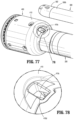
- FIG. 77 is a rear, perspective view of the reload and more distal end portion of the adapter assembly, illustrating the irrigation tube separated therefrom;
- FIG. 78 is an enlarged view of the indicated area of detail of FIG. 77 ;
- FIG. 79 is a perspective view of the irrigation tube
- FIG. 80 is an enlarged view of the indicated area of detail of FIG. 79 ;
- FIG. 81 is an enlarged view of the indicated area of detail of FIG. 79 ;
- FIGS. 82 A-F illustrate a flow chart of a method for operating the handheld surgical device of FIG. 1 according to an embodiment of the present disclosure
- FIG. 83 is a schematic diagram illustrating travel distance and speed of the anvil assembly and a corresponding motor during a clamping sequence performed by the handheld surgical device of FIG. 1 according to an embodiment of the present disclosure
- FIG. 84 is a schematic diagram illustrating travel distance and speed of the driver and a corresponding motor during a stapling sequence performed by the handheld surgical device of FIG. 1 according to an embodiment of the present disclosure
- FIG. 85 is a schematic diagram illustrating travel distance and speed of the knife assembly and a corresponding motor during a cutting sequence performed by the handheld surgical device of FIG. 1 according to an embodiment of the present disclosure
- FIG. 86 illustrates a flow chart of a method for controlled tissue compression algorithm executed by the handheld surgical device of FIG. 1 according to an embodiment of the present disclosure
- FIGS. 87 A-B illustrate a flow chart of a method for a stapling algorithm executed by the handheld surgical device of FIG. 1 according to an embodiment of the present disclosure
- FIGS. 88 A-B illustrate a flow chart of a method for a cutting algorithm executed by the handheld surgical device of FIG. 1 according to an embodiment of the present disclosure
- FIG. 89 is a schematic diagram of the the handheld surgical device, the adapter assembly, and the reload according to an embodiment of the present disclosure.
- distal refers to that portion of the adapter assembly or surgical device, or component thereof, farther from the user
- proximal refers to that portion of the adapter assembly or surgical device, or component thereof, closer to the user.
- a surgical device in accordance with an embodiment of the present disclosure, is a handheld surgical device in the form of a powered electromechanical handle assembly configured for selective attachment thereto of a plurality of different reloads, via a plurality of respective adapter assemblies, that are each configured for actuation and manipulation by the powered electromechanical handle assembly.
- the surgical device includes a handle assembly 100 which is configured for selective connection with an adapter assembly 200 , and, in turn, adapter assembly 200 is configured for selective connection with a selected reload 400 (of a plurality of reloads), which are configured to produce a surgical effect on tissue of a patient.
- handle assembly 100 includes a power handle 101 , and an outer shell housing 10 configured to selectively receive and encase power handle 101 .
- Outer shell housing 10 includes a distal half-section 10 a and a proximal half-section 10 b pivotably connected to distal half-section 10 a by a hinge 16 located along an upper edge of distal half-section 10 a and proximal half-section 10 b .
- distal and proximal half-sections 10 a , 10 b define a shell cavity 10 c therein in which power handle 101 is selectively situated.
- Distal and proximal half-sections 10 a , 10 b of shell housing 10 are divided along a plane that traverses a longitudinal axis “X” of adapter assembly 200 .
- Each of distal and proximal half-sections 10 a , 10 b of shell housing 10 includes a respective upper shell portion 12 a , 12 b , and a respective lower shell portion 14 a , 14 b .
- Lower shell portions 14 a , 14 b define a snap closure feature 18 for selectively securing lower shell portions 14 a , 14 b to one another and for maintaining shell housing 10 in a closed condition.
- Shell housing 10 includes right-side and left-side snap closure features 18 a for further securing distal and proximal half-sections 10 a , 10 b of shell housing 10 to one another.
- Distal half-section 10 a of shell housing 10 defines a connecting portion 20 configured to accept a corresponding drive coupling assembly 210 of Adapter assembly 200 .
- distal half-section 10 a of shell housing 10 has a recess 20 that receives a portion of drive coupling assembly 210 of Adapter assembly 200 when Adapter assembly 200 is mated to handle assembly 100 .
- Connecting portion 20 of distal half-section 10 a defines a pair of axially extending guide rails 20 a , 20 b projecting radially inward from inner side surfaces thereof.
- Guide rails 20 a , 20 b assist in rotationally orienting Adapter assembly 200 relative to handle assembly 100 when Adapter assembly 200 is mated to handle assembly 100 .
- Connecting portion 20 of distal half-section 10 a defines three apertures 22 a , 22 b , 22 c formed in a distally facing surface thereof and which are arranged in a common plane or line with one another.
- Connecting portion 20 of distal half-section 10 a also defines an elongate slot 24 (to contain connector 66 , see FIG. 3 ) also formed in the distally facing surface thereof.
- Connecting portion 20 of distal half-section 10 a further defines a female connecting feature 26 (see FIG. 2 ) formed in a surface thereof.
- Female connecting feature 26 selectively engages with a male connecting feature of Adapter assembly 200 , as will be described in greater detail below.
- Distal half-section 10 a of shell housing 10 supports a distal facing toggle control button 30 .
- Toggle control button 30 is capable of being actuated in a left, right, up and down direction upon application of a corresponding force thereto or a depressive force thereto.
- Distal half-section 10 a of shell housing 10 supports a right-side pair of control buttons 32 a , 32 b (see FIG. 3 ); and a left-side pair of control button 34 a , 34 b (see FIG. 2 ).
- Right-side control buttons 32 a , 32 b and left-side control buttons 34 a , 34 b are capable of being actuated upon application of a corresponding force thereto or a depressive force thereto.
- Proximal half-section 10 b of shell housing 10 supports a right-side fire button 36 a (see FIG. 3 ) and a left-side fire button 36 b (see FIG. 2 ).
- Right-side fire button 36 a and left-side fire button 36 b are capable of being actuated upon application of a corresponding force thereto or a depressive force thereto.
- Distal half-section 10 a and proximal half-section 10 b of shell housing 10 are fabricated from a polycarbonate, and are clear or transparent or may be overmolded.
- handle assembly 100 includes an insertion guide 50 that is configured and shaped to seat on and entirely surround a distal facing edge 10 d ( FIGS. 3 and 9 ) of proximal half-section 10 b .
- Insertion guide 50 includes a body portion 52 defining a central opening therein, and a hand/finger grip tab 54 extending from a bottom of body portion 52 .
- insertion guide 50 In use, when body portion 52 of insertion guide 50 is seated on distal facing edge 10 d of proximal half-section 10 b , the central opening of insertion guide 50 provides access to shell cavity 10 c of shell housing 10 for insertion of a non-sterile power handle 101 of handle assembly 100 into proximal half-section 10 b of sterile shell housing 10 .
- shell housing 10 includes a sterile barrier plate assembly 60 selectively supported in distal half-section 10 a .
- sterile barrier plate assembly 60 is disposed behind connecting portion 20 of distal half-section 10 a and within shell cavity 10 c of shell housing 10 .
- Plate assembly 60 includes a plate 62 rotatably supporting three coupling shafts 64 a , 64 b , 64 c .
- Each coupling shaft 64 a , 64 b , 64 c extends from opposed sides of plate 62 and has a tri-lobe transverse cross-sectional profile.
- Each coupling shaft 64 a , 64 b , 64 c extends through a respective aperture 22 b , 22 c , 22 a of connecting portion 20 of distal half-section 10 a when sterile barrier plate assembly 60 is disposed within shell cavity 10 c of shell housing 10 .
- Plate assembly 60 further includes an electrical connector 66 supported on plate 62 .
- Electrical connector 66 extends from opposed sides of plate 62 .
- Each coupling shaft 64 a , 64 b , 64 c extends through respective aperture 22 a , 22 b , 22 c of connecting portion 20 of distal half-section 10 a of shell housing 10 when sterile barrier plate assembly 60 is disposed within shell cavity 10 c of shell housing 10 .
- Electrical connector 66 includes a chip and defines a plurality of contact paths each including an electrical conduit for extending an electrical connection across plate 62 .
- distal ends of coupling shaft 64 a , 64 b , 64 c and a distal end of pass-through connector 66 are disposed or situated within connecting portion 20 of distal half-section 10 a of shell housing 10 , and electrically and/or mechanically engage respective corresponding features of Adapter assembly 200 , as will be described in greater detail below.
- a new and/or sterile shell housing 10 in an open configuration (e.g., distal half-section 10 a separated from proximal half-section 10 b , about hinge 16 ), and with insertion guide 50 in place against the distal edge 10 d of proximal half-section 10 b of shell housing 10 , power handle 101 is inserted through the central opening of insertion guide 50 and into shell cavity 10 c of shell housing 10 .
- insertion guide 50 is removed from proximal half-section 10 b and distal half-section 10 a is pivoted, about hinge 16 , to a closed configuration for shell housing 10 .
- snap closure feature 18 of lower shell portion 14 a of distal half-section 10 a engages snap closure feature 18 of lower shell portion 14 b of proximal half-section 10 b .
- right-side and left-side snap closure features 18 a engage to further maintain shell housing 10 in the closed configuration.
- snap closure feature 18 of lower shell portion 14 a of distal half-section 10 a is disengaged from snap closure feature 18 of lower shell portion 14 b of proximal half-section 10 b , and right-side and left-side snap closure features 18 a are disengaged, such that distal half-section 10 a may be pivoted, about hinge 16 , away from proximal half-section 10 b to open shell housing 10 .
- power handle 101 is removed from shell cavity 10 c of shell housing 10 (specifically from proximal half-section 10 b of shell housing 10 ), and shell housing 10 is discarded.
- Power handle 101 is then disinfected and cleaned. Power handle 101 is not to be submerged and is not to be sterilized.
- handle assembly 100 includes a power handle 101 .
- Power handle 101 includes an inner handle housing 110 having a lower housing portion 104 and an upper housing portion 108 extending from and/or supported on lower housing portion 104 .
- Lower housing portion 104 and upper housing portion 108 are separated into a distal half-section 110 a and a proximal half-section 110 b connectable to distal half-section 110 a by a plurality of fasteners.
- distal and proximal half-sections 110 a , 110 b define an inner handle housing 110 having an inner housing cavity 110 c therein in which a power-pack core assembly 106 is situated.
- Power-pack core assembly 106 is configured to control the various operations of handle assembly 100 , as will be set forth in additional detail below.
- Distal half-section 110 a of inner handle housing 110 defines a distal opening 111 a therein which is configured and adapted to support a control plate 160 of power-pack core assembly 106 .
- Control plate 160 of power handle 101 abuts against a rear surface of plate 62 of sterile barrier plate assembly 60 of shell housing 10 when power handle 101 is disposed within shell housing 10 .
- distal half-section 110 a of inner handle housing 110 supports a distal toggle control interface 130 that is in operative registration with distal toggle control button 30 of shell housing 10 .
- actuation of toggle control button 30 exerts a force on toggle control interface 130 .
- Distal half-section 110 a of inner handle housing 110 also supports a right-side pair of control interfaces 132 a , 132 b , and a left-side pair of control interfaces 134 a , 134 b .
- actuation of one of the right-side pair of control buttons 32 a , 32 b or the left-side pair of control button 34 a , 34 b of distal half-section 10 a of shell housing 10 exerts a force on a respective one of the right-side pair of control interfaces 132 a , 132 b or the left-side pair of control interfaces 134 a , 134 b of distal half-section 110 a of inner handle housing 110 .
- control button 30 right-side fire button 36 a or the left-side fire button 36 b , the right-side pair of control interfaces 132 a , 132 b , and the left-side pair of control interfaces 134 a , 134 b of distal half-section 110 a of inner handle housing 110 will be deactived or fail to function unless shell housing 10 has been validated.
- Proximal half-section 110 b of inner handle housing 110 defines a right-side control aperture 136 a and a left-side control aperture 136 b .
- actuation of one of the right-side fire button 36 a or the left-side fire button 36 b of proximal half-section 10 b of shell housing 10 extends the right-side fire button 36 a or the left-side fire button 36 b into and across the right-side control aperture 136 a or the left-side control aperture 136 b of the proximal half-section 110 b of inner handle housing 110 .
- inner handle housing 110 provides a housing in which power-pack core assembly 106 is situated.
- Power-pack core assembly 106 includes a battery circuit 140 , a controller circuit board 142 and a rechargeable battery 144 configured to supply power to any of the electrical components of handle assembly 100 .
- Controller circuit board 142 includes a motor controller circuit board 142 a , a main controller circuit board 142 b , and a first ribbon cable 142 c interconnecting motor controller circuit board 142 a and main controller circuit board 142 b.
- Power-pack core assembly 106 further includes a display screen 146 supported on main controller circuit board 142 b .
- Display screen 146 is visible through a clear or transparent window 110 d (see FIGS. 12 and 17 ) provided in proximal half-section 110 b of inner handle housing 110 .
- Power-pack core assembly 106 further includes a first motor 152 , a second motor 154 , and a third motor 156 each electrically connected to controller circuit board 142 and battery 144 .
- Motors 152 , 154 , 156 are disposed between motor controller circuit board 142 a and main controller circuit board 142 b .
- Each motor 152 , 154 , 156 includes a respective motor shaft 152 a , 154 a , 156 a extending therefrom.
- Each motor shaft 152 a , 154 a , 156 a has a tri-lobe transverse cross-sectional profile for transmitting rotative forces or torque.
- Each motor 152 , 154 , 156 is controlled by a respective motor controller.
- the motor controllers are disposed on motor controller circuit board 142 a and are A3930/31K motor drivers from Allegro Microsystems, Inc.
- the A3930/31K motor drivers are designed to control a 3-phase brushless DC (BLDC) motor with N-channel external power MOSFETs, such as the motors 152 , 154 , 156 .
- Each of the motor controllers is coupled to a main controller disposed on the main controller circuit board 142 b .
- the main controller is also coupled to memory, which is also disposed on the main controller circuit board 142 b .
- the main controller is an ARM Cortex M4 processor from Freescale Semiconductor, Inc, which includes 1024 kilobytes of internal flash memory.
- the main controller communicates with the motor controllers through an FPGA, which provides control logic signals (e.g., coast, brake, etc.).
- the control logic of the motor controllers then outputs corresponding energization signals to their respective motors 152 , 154 , 156 using fixed-frequency pulse width modulation (PWM).
- PWM pulse width modulation
- Each motor 152 , 154 , 156 is supported on a motor bracket 148 such that motor shaft 152 a , 154 a , 156 a are rotatably disposed within respective apertures of motor bracket 148 .
- motor bracket 148 rotatably supports three rotatable drive connector sleeves 152 b , 154 b , 156 b that are keyed to respective motor shafts 152 a , 154 a , 156 a of motors 152 , 154 , 156 .
- Drive connector sleeves 152 b , 154 b , 156 b non-rotatably receive proximal ends of respective coupling shaft 64 a , 64 b , 64 c of plate assembly 60 of shell housing 10 , when power handle 101 is disposed within shell housing 10 .
- Drive connector sleeves 152 b , 154 b , 156 b are each spring biased away from respective motors 152 , 154 , 156 .
- Rotation of motor shafts 152 a , 154 a , 156 a by respective motors 152 , 154 , 156 function to drive shafts and/or gear components of Adapter assembly 200 in order to perform the various operations of handle assembly 100 .
- motors 152 , 154 , 156 of power-pack core assembly 106 are configured to drive shafts and/or gear components of adapter assembly 200 in order to selectively extend/retract a trocar member 274 of a trocar assembly 270 of adapter assembly 200 ; to, open/close reload 400 (when an anvil assembly 510 is connected to trocar member 274 of trocar assembly 270 ), to fire an annular array of staples of reload 400 , and to fire an annular knife 444 of reload 400 .
- Motor bracket 148 also supports an electrical receptacle 149 .
- Electrical receptacle 149 is in electrical connection with main controller circuit board 142 b by a second ribbon cable 142 d .
- Electrical receptacle 149 defines a plurality of electrical slots for receiving respective electrical contacts or blades extending from pass-through connector 66 of plate assembly 60 of shell housing 10 .
- each of coupling shafts 64 a , 64 b , 64 c of plate assembly 60 of shell housing 10 of handle assembly 100 couples with corresponding rotatable connector sleeves 218 , 222 , 220 of adapter assembly 200 (see FIG. 22 ).
- the interface between corresponding first coupling shaft 64 a and first connector sleeve 218 , the interface between corresponding second coupling shaft 64 b and second connector sleeve 222 , and the interface between corresponding third coupling shaft 64 c and third connector sleeve 220 are keyed such that rotation of each of coupling shafts 64 a , 64 b , 64 c of handle assembly 100 causes a corresponding rotation of the corresponding connector sleeve 218 , 222 , 220 of adapter assembly 200 .
- coupling shafts 64 a , 64 b , 64 c of handle assembly 100 with connector sleeves 218 , 222 , 220 of adapter assembly 200 allows rotational forces to be independently transmitted via each of the three respective connector interfaces.
- the coupling shafts 64 a , 64 b , 64 c of handle assembly 100 are configured to be independently rotated by respective motors 152 , 154 , 156 .
- each of coupling shafts 64 a , 64 b , 64 c of handle assembly 100 has a keyed and/or substantially non-rotatable interface with respective connector sleeves 218 , 222 , 220 of adapter assembly 200 , when adapter assembly 200 is coupled to handle assembly 100 , rotational force(s) are selectively transferred from motors 152 , 154 , 156 of handle assembly 100 to adapter assembly 200 .
- the selective rotation of coupling shaft(s) 64 a , 64 b , 64 c of handle assembly 100 allows handle assembly 100 to selectively actuate different functions of reload 400 .
- selective and independent rotation of first coupling shaft 64 a of handle assembly 100 corresponds to the selective and independent extending/retracting of trocar member 274 of adapter assembly 200 and/or the selective and independent opening/closing of reload 400 (when anvil assembly 510 is connected to trocar member 274 ).
- the selective and independent rotation of third coupling shaft 64 c of handle assembly 100 corresponds to the selective and independent firing of an annular array of staples of reload 400 .
- the selective and independent rotation of second coupling shaft 64 b of handle assembly 100 corresponds to the selective and independent firing of an annular knife 444 of reload 400 .
- power-pack core assembly 106 further includes a switch assembly 170 supported within distal half-section 110 a of inner handle housing 110 , at a location beneath and in registration with toggle control interface 130 , the right-side pair of control interfaces 132 a , 132 b , and the left-side pair of control interfaces 134 a , 134 b .
- Switch assembly 170 includes a first set of four push-button switches 172 a - 172 d arranged around stem 30 a of toggle control button 30 of outer shell housing 10 when power handle 101 is disposed within outer shell housing 10 .
- Switch assembly 170 also includes a second pair of push-button switches 174 a , 174 b disposed beneath right-side pair of control interfaces 132 a , 132 b of distal half-section 110 a of inner handle housing 110 when power handle 101 is disposed within outer shell housing 10 .
- Switch assembly 170 further includes a third pair of push-button switches 176 a , 176 b disposed beneath left-side pair of control interfaces 134 a , 134 b of distal half-section 110 a of inner handle housing 110 when power handle 101 is disposed within outer shell housing 10 .
- Power-pack core assembly 106 includes a single right-side push-button switch 178 a disposed beneath right-side control aperture 136 a of proximal half-section 110 b of inner handle housing 110 , and a single left-side push-button switch 178 b disposed beneath left-side control aperture 136 b of proximal half-section 110 b of inner handle housing 110 .
- Push-button switches 178 a , 178 b are supported on controller circuit board 142 .
- Push-button switches 178 a , 178 b are disposed beneath right-side fire button 36 a and left-side fire button 36 b of proximal half-section 10 b of shell housing 10 when power handle 101 is disposed within outer shell housing 10 .
- controller circuit board 142 causes controller circuit board 142 to provide appropriate signals to motor 152 to activate, to retract a trocar member 274 of adapter assembly 200 and/or to close handle assembly 100 (e.g., approximate anvil assembly 510 relative to reload 400 ).
- fire switch 178 a or 178 b of power handle 101 causes controller circuit board 142 to provide appropriate signals to motors 154 and 156 to activate, as appropriate, to fire staples of reload 400 , and then to advance (e.g., fire) and retract an annular knife 444 of reload 400 .
- switches 174 a , 174 b by right-hand thumb of user or switches 176 a , 176 b (by left-hand thumb of user) of switch assembly 170 , corresponding to respective actuation of right-side pair of control buttons 32 a , 32 b or left-side pair of control button 34 a , 34 b , causes controller circuit board 142 to provide appropriate signals to motor 152 to activate, to advance or retract trocar member 274 of adapter assembly 200 .
- power-pack core assembly 106 of handle assembly 100 includes a USB connector 180 supported on main controller circuit board 142 b of controller circuit board 142 .
- USB connector 180 is accessible through control plate 160 of power-pack core assembly 106 .
- USB connector 180 is covered by plate 62 of sterile barrier plate assembly 60 of shell housing 10 .
- handle assembly 100 is configured for selective connection with adapter assembly 200 , and, in turn, adapter assembly 200 is configured for selective connection with reload 400 .
- Adapter assembly 200 is configured to convert a rotation of coupling shaft(s) 64 a , 64 b , 64 c of handle assembly 100 into axial translation useful for advancing/retracting trocar member 274 of adapter assembly 200 , for opening/closing handle assembly 100 (when anvil assembly 510 is connected to trocar member 274 ), for firing staples of reload 400 , and for firing annular knife 444 of reload 400 , as illustrated in FIG. 22 , and as will be described in greater detail below.
- Adapter assembly 200 includes a first drive transmitting/converting assembly for interconnecting first coupling shaft 64 a of handle assembly 100 and an anvil assembly 510 , wherein the first drive transmitting/converting assembly converts and transmits a rotation of first coupling shaft 64 a of handle assembly 100 to an axial translation of trocar member 274 of trocar assembly 270 , and in turn, the anvil assembly 510 , which is connected to trocar member 274 , to open/close handle assembly 100 .
- Adapter assembly 200 includes a second drive transmitting/converting assembly for interconnecting third coupling shaft 64 c of handle assembly 100 and a second axially translatable drive member of reload 400 , wherein the second drive transmitting/converting assembly converts and transmits a rotation of third coupling shaft 64 c of handle assembly 100 to an axial translation of an outer flexible band assembly 255 of adapter assembly 200 , and in turn, a driver adapter 432 of a staple driver assembly 430 of reload 400 to fire staples from a staple cartridge 420 of reload 400 and against anvil assembly 510 .
- Adapter assembly 200 includes a third drive transmitting/converting assembly for interconnecting second coupling shaft 64 b of handle assembly 100 and a third axially translatable drive member of reload 400 , wherein the third drive transmitting/converting assembly converts and transmits a rotation of second coupling shaft 64 b of handle assembly 100 to an axial translation of an inner flexible band assembly 265 of adapter assembly 200 , and in turn, a knife assembly 440 of reload 400 to fire annular knife 444 against anvil assembly 510 .
- adapter assembly 200 includes an outer knob housing 202 and an outer tube 206 extending from a distal end of knob housing 202 .
- Knob housing 202 and outer tube 206 are configured and dimensioned to house the components of adapter assembly 200 .
- Knob housing 202 includes a drive coupling assembly 210 which is configured and adapted to connect to connecting portion 108 of handle housing 102 of handle assembly 100 .
- Adapter assembly 200 is configured to convert a rotation of either of first, second or third coupling shafts 64 a , 64 b , 64 c , respectively, of handle assembly 100 , into axial translations useful for operating trocar assembly 270 of adapter assembly 200 , anvil assembly 510 , and/or staple driver assembly 430 or knife assembly 440 of reload 400 , as will be described in greater detail below.
- adapter assembly 200 includes a proximal inner housing member 204 disposed within knob housing 202 .
- Inner housing member 204 rotatably supports a first rotatable proximal drive shaft 212 , a second rotatable proximal drive shaft 214 , and a third rotatable proximal drive shaft 216 therein.
- Each proximal drive shaft 212 , 214 , 216 functions as a rotation receiving member to receive rotational forces from respective coupling shafts 64 a , 64 c and 64 b of handle assembly 100 , as described in greater detail below.
- drive coupling assembly 210 of adapter assembly 200 is also configured to rotatably support first, second and third connector sleeves 218 , 222 and 220 , respectively, arranged in a common plane or line with one another.
- Each of connector sleeves 218 , 220 , 222 is configured to mate with respective first, second and third coupling shafts 64 a , 64 c and 64 b of handle assembly 100 , as described above.
- Each of connector sleeves 218 , 220 , 222 is further configured to mate with a proximal end of respective first, second and third proximal drive shafts 212 , 214 , 216 of adapter assembly 200 .
- Drive coupling assembly 210 of adapter assembly 200 also includes, as illustrated in FIGS. 26 , 34 , 35 and 40 , a first, a second and a third biasing member 224 , 226 and 228 disposed distally of respective first, second and third connector sleeves 218 , 222 , 220 .
- Each of biasing members 224 , 226 and 228 is disposed about respective first, second and third rotatable proximal drive shaft 212 , 216 and 214 .
- Biasing members 224 , 226 and 228 act on respective connector sleeves 218 , 222 and 220 to help maintain connector sleeves 218 , 222 and 220 engaged with the distal end of respective coupling shafts 64 a , 64 b and 64 c of handle assembly 100 when adapter assembly 200 is connected to handle assembly 100 .
- first, second and third biasing members 224 , 226 and 228 function to bias respective connector sleeves 218 , 222 and 220 in a proximal direction. In this manner, during connection of handle assembly 100 to adapter assembly 200 , if first, second and or third connector sleeves 218 , 222 and/or 220 is/are misaligned with coupling shafts 64 a , 64 b and 64 c of handle assembly 100 , first, second and/or third biasing member(s) 224 , 226 and/or 228 are compressed.
- coupling shafts 64 a , 64 c and 64 b of handle assembly 100 will rotate and first, second and/or third biasing member(s) 224 , 228 and/or 226 will cause respective first, second and/or third connector sleeve(s) 218 , 220 and/or 222 to slide back proximally, effectively connecting coupling shafts 64 a , 64 c and 64 b of handle assembly 100 to first, second and/or third proximal drive shaft(s) 212 , 214 and 216 of drive coupling assembly 210 .
- adapter assembly 200 includes a first, a second and a third force/rotation transmitting/converting assembly 240 , 250 , 260 , respectively, disposed within inner housing member 204 and outer tube 206 .
- Each force/rotation transmitting/converting assembly 240 , 250 , 260 is configured and adapted to transmit or convert a rotation of a first, second and third coupling shafts 64 a , 64 c and 64 b of handle assembly 100 into axial translations to effectuate operation of trocar assembly 270 of adapter assembly 200 , and of staple driver assembly 430 or knife assembly 440 of reload 400 .
- first force/rotation transmitting/converting assembly 240 includes first rotatable proximal drive shaft 212 , as described above, a second rotatable proximal drive shaft 281 , a rotatable distal drive shaft 282 , and a coupling member 286 , each of which are supported within inner housing member 204 , drive coupling assembly 210 and/or an outer tube 206 of adapter assembly 200 .
- First force/rotation transmitting/converting assembly 240 functions to extend/retract trocar member 274 of trocar assembly 270 of adapter assembly 200 , and to open/close handle assembly 100 (when anvil assembly 510 is connected to trocar member 274 ).
- First rotatable proximal drive shaft 212 includes a non-circular or shaped proximal end portion configured for connection with first connector 218 which is connected to respective first coupling shaft 64 a of handle assembly 100 .
- First rotatable proximal drive shaft 212 includes a non-circular recess formed therein which is configured to key with a respective complimentarily shaped proximal end portion 281 a of second rotatable proximal drive shaft 281 .
- Second rotatable proximal drive shaft 281 includes a distal end portion 281 b defining an oversized recess therein which is configured to receive a proximal end portion 282 a of first rotatable distal drive shaft 282 .
- Proximal end portion 282 a of first rotatable distal drive shaft 282 is pivotally secured within the recess in distal end 281 b of second rotatable proximal drive shaft 281 by a pin 283 a received through the oversized recess in distal end portion 281 b of second rotatable proximal drive shaft 281 .
- First rotatable distal drive shaft 282 includes a proximal end portion 282 a , and a distal end portion 282 b which is pivotally secured within a recess of coupling member 286 .
- Distal end portion 282 b of first rotatable distal drive shaft 282 is pivotally secured within a recess in a proximal end of coupling member 286 by a pin 283 b received through the recess in the proximal end portion of coupling member 286 .
- Proximal and distal end portions 282 a , 282 b of first rotatable distal drive shaft 282 define oversized openings for receiving pins 283 a , 283 b , respectively.
- Coupling member 286 includes a proximal end 286 a defining a recess 286 c for receiving distal end portion 282 b of first rotatable distal drive shaft 282 , a distal end 286 b defining a recess 286 d for operably receiving a non-circular stem 276 c on proximal end 276 a of a drive screw 276 of trocar assembly 270 .
- First force/rotation transmitting/converting assembly 240 further includes a trocar assembly 270 removably supported in a distal end of outer tube 206 .
- Trocar assembly 270 includes an outer housing 272 , a trocar member 274 slidably disposed within tubular outer housing 272 , and a drive screw 276 operably received within trocar member 274 for axially moving trocar member 274 relative to tubular housing 272 .
- trocar member 274 includes a proximal end 274 a having an inner threaded portion which engages a threaded distal portion 276 b of drive screw 276 .
- Trocar member 274 further includes at least one longitudinally extending flat formed in an outer surface thereof which mates with a corresponding flat formed in tubular housing 272 thereby inhibiting rotation of trocar member 274 relative to tubular housing 272 as drive screw 276 is rotated.
- a distal end 274 b of trocar member 274 is configured to selectively engage anvil assembly 510 ( FIGS. 73 - 75 ).
- Tubular housing 272 of trocar assembly 270 is axially and rotationally fixed within outer tube 206 of adapter assembly 200 .
- Tubular housing 272 defines a pair of radially opposed, and radially oriented openings 272 a which are configured and dimensioned to cooperate with a pair of lock pins 275 c of a trocar assembly release mechanism 275 .
- adapter assembly 200 includes a support block 292 fixedly disposed within outer tube 206 .
- Support block 292 is disposed proximal of a connector sleeve 290 and proximal of a strain sensor 320 a of a strain gauge assembly 320 , as described in greater detail below.
- the pair of lock pins 275 c extend through support block 292 and into tubular housing 272 of trocar assembly 270 to connect trocar assembly 270 to adapter assembly 200 .
- trocar assembly release mechanism 275 includes a release button 275 a pivotally supported on support block 292 and in outer tube 206 .
- Release button 275 a is spring biased to a locked/extended condition.
- Trocar assembly release mechanism 275 further includes a spring clip 275 b connected to release button 275 a , wherein spring clip 275 b includes a pair of legs that extend through support block 292 and transversely across trocar assembly 270 .
- Each of the pair of legs of spring clip 275 b extends through a respective lock pin 275 c which is slidably disposed within a respective radial opening 272 a of tubular housing 272 and radial opening 292 a of support block 292 (see FIG. 31 ).
- release button 275 a moves spring clip 275 b transversely relative to trocar assembly 270 .
- the pair of legs of spring clip 275 b translate through the pair of lock pins 275 c such that a goose-neck in each leg acts to cam and urge the pair of lock pins 275 c radially outward.
- Each of the pair of lock pins 275 c is urged radially outward by a distance sufficient that each of the pair of lock pins 275 c clears respective opening 272 a of tubular housing 272 .
- trocar assembly 270 may be axially withdrawn from within the distal end of outer tube 206 of adapter assembly 200 .
- first rotatable proximal drive shaft 212 is rotated, due to a rotation of first connector sleeve 218 , as a result of the rotation of first coupling shaft 64 a of handle assembly 100 , second rotatable distal drive shaft 281 is caused to be rotated.
- Rotation of second rotatable distal drive shaft 281 results in contemporaneous rotation of first rotatable distal drive shaft 282 .
- Rotation of first rotatable distal drive shaft 282 causes contemporaneous rotation of coupling member 286 , which, in turn, causes contemporaneous rotation of drive screw 276 of trocar assembly 270 .
- strain sensor 320 a of strain gauge assembly 320 may be measured by strain sensor 320 a of strain gauge assembly 320 in order to:
- strain sensor 320 a of strain gauge assembly 320 of adapter assembly 200 measures and monitors the retraction of trocar member 274 , as described above.
- a reaction force is exerted on head assembly 512 which is in a generally distal direction. This distally directed reaction force is communicated from head assembly 512 to center rod assembly 514 of anvil assembly 510 , which in turn is communicated to trocar assembly 270 .
- Trocar assembly 270 then communicates the distally directed reaction force to the pair of pins 275 c of trocar assembly release mechanism 275 , which in turn then communicate the reaction force to support block 292 .
- Support block 292 then communicates the distally directed reaction force to strain sensor 320 a of strain gauge assembly 320 .
- Strain sensor 320 a of strain gauge assembly 320 is a device configured to measure strain (a dimensionless quantity) on an object that it is adhered to (e.g., support block 292 ), such that, as the object deforms, a metallic foil of the strain sensor 320 a is also deformed, causing an electrical resistance thereof to change, which change in resistance is then used to calculate loads experienced by trocar assembly 270 .
- Strain sensor 320 a of strain gauge assembly 320 then communicates signals to main controller circuit board 142 b of power-pack core assembly 106 of handle assembly 100 . Graphics are then displayed on display screen 146 of power-pack core assembly 106 of handle assembly 100 to provide the user with real-time information related to the status of the firing of handle assembly 100 .
- second force/rotation transmitting/converting assembly 250 of adapter assembly 200 includes second proximal drive shaft 214 , as described above, a first coupling shaft 251 , a planetary gear set 252 , a staple lead screw 253 , and a staple driver 254 , each of which are supported within inner housing member 204 , drive coupling assembly 210 and/or an outer tube 206 of adapter assembly 200 .
- Second force/rotation transmitting/converting assembly 250 functions to fire staples of reload 400 for formation against anvil assembly 510 .
- Second rotatable proximal drive shaft 214 includes a non-circular or shaped proximal end portion configured for connection with second connector or coupler 220 which is connected to respective second coupling shaft 64 c of handle assembly 100 .
- Second rotatable proximal drive shaft 214 further includes a distal end portion 214 b having a spur gear non-rotatably connected thereto.
- First coupling shaft 251 of second force/rotation transmitting/converting assembly 250 includes a proximal end portion 251 a having a spur gear non-rotatably connected thereto, and a distal end portion 251 b having a spur gear non-rotatably connected thereto.
- the spur gear at the proximal end portion 251 a of first coupling shaft 251 is in meshing engagement with the spur gear at the distal end portion 214 b of the second rotatable proximal drive shaft 214 .
- Planetary gear set 252 of second force/rotation transmitting/converting assembly 250 includes a first cannulated sun gear 252 a , a first set of planet gears 252 b , a ring gear 252 c , a second set of planet gears 252 d , and a second cannulated sun gear 252 e .
- First sun gear 252 a is in meshing engagement with the spur gear at the distal end portion 251 b of first coupling shaft 251 .
- the first set of planet gears 252 b are interposed between, and are in meshing engagement with, first sun gear 252 a and ring gear 252 c .
- the second set of planet gears 252 d are interposed between, and are in meshing engagement with, second sun gear 252 e and ring gear 252 c .
- Ring gear 252 c is non-rotatably supported in outer tube 206 of adapter assembly 200 .
- Planetary gear set 252 of second force/rotation transmitting/converting assembly 250 includes a washer 252 f disposed within ring gear 252 c , and between the first set of planet gears 252 b and the second set of planet gears 252 d .
- the first set of planet gears 252 b are rotatably supported radially about washer 252 f
- second sun gear 252 e is non-rotatably connected to a center of washer 252 f.
- Staple lead screw 253 of second force/rotation transmitting/converting assembly 250 includes a proximal flange 253 a and a distal threaded portion 253 b extending from flange 253 a .
- Staple lead screw 253 defines a lumen 253 c therethrough.
- the second set of planet gears 252 d are rotatably supported radially about proximal flange 253 a of staple lead screw 253 .
- Staple driver 254 of second force/rotation transmitting/converting assembly 250 includes a central threaded lumen 254 a extending therethrough and is configured and dimensioned to support distal threaded portion 253 b of staple lead screw 253 therein.
- Staple driver 254 includes a pair of tabs 254 b projecting radially from an outer surface thereof, and which are configured for connection to outer flexible band assembly 255 of adapter assembly 200 , as will be described in greater detail below.
- second force/rotation transmitting/converting assembly 250 of adapter assembly 200 includes an outer flexible band assembly 255 secured to staple driver 254 .
- Outer flexible band assembly 255 includes first and second flexible bands 255 a , 255 b laterally spaced and connected at proximal ends thereof to a support ring 255 c and at distal ends thereof to a proximal end of a support base 255 d .
- Each of first and second flexible bands 255 a , 255 b is attached to support ring 255 c and support base 255 d.
- Outer flexible band assembly 255 further includes first and second connection extensions 255 e , 255 f extending proximally from support ring 255 c .
- First and second connection extensions 255 e , 255 f are configured to operably connect outer flexible band assembly 255 to staple driver 254 of second force/rotation transmitting/converting assembly 250 .
- each of first and second connection extensions 255 e , 255 f defines an opening configured to receive a respective tab 254 b of staple driver 254 . Receipt of tabs 254 b of staple driver 254 within the openings of respective first and second connection extensions 255 e , 255 f secures outer flexible band assembly 255 to staple driver 254 of second force/rotation transmitting/converting assembly 250 .
- Support base 255 d extends distally from flexible bands 255 a , 255 b and is configured to selectively contact driver adapter 432 of staple driver assembly 430 of reload 400 .
- Flexible bands 255 a , 255 b are fabricated from stainless steel 301 half hard and are configured to transmit axial pushing forces along a curved path.
- Second force/rotation transmitting/converting assembly 250 and outer flexible band assembly 255 are configured to receive first rotatable proximal drive shaft 212 , first rotatable distal drive shaft 282 , and trocar assembly 270 of first force/rotation transmitting/converting assembly 240 therethrough.
- first rotatable proximal drive shaft 212 is non-rotatably connected to second rotatable proximal drive shaft 281 which in turn is rotatably disposed within and through first cannulated sun gear 252 a of first planetary gear set 252 , second cannulated sun gear 252 e of planetary gear set 252 , staple lead screw 253 , and staple driver 254 .
- Second force/rotation transmitting/converting assembly 250 and outer flexible band assembly 255 are also configured to receive third force/rotation transmitting/converting assembly 260 therethrough.
- inner flexible band assembly 265 is slidably disposed within and through outer flexible band assembly 255 .
- First rotatable distal drive shaft 282 of first force/rotation transmitting/converting assembly 240 is rotatably disposed within support base 255 d of outer flexible band assembly 255
- trocar member 274 of trocar assembly 270 of first force/rotation transmitting/converting assembly 240 is slidably disposed within support base 255 d of outer flexible band assembly 255 .
- Outer flexible band assembly 255 is also configured to receive inner flexible band assembly 265 therethrough.
- first coupling shaft 251 is caused to be rotated, which in turn causes first cannulated sun gear 252 a to rotate.
- Rotation of first cannulated sun gear 252 a results in contemporaneous rotation of the first set of planet gears 252 b , which in turn causes washer 252 f to contemporaneously rotate second cannulated sun gear 252 e .
- Second cannulated sun gear 252 e results in contemporaneous rotation of the second set of planet gears 252 d , which in turn causes contemporaneous rotation of staple lead screw 253 .
- staple driver 254 is caused to be axially translated, which in turn causes outer flexible band assembly 255 to be axially translated.
- support base 255 d presses against driver adapter 432 of staple driver assembly 430 of reload 400 to distally advance driver 434 and fire staples “S” ( FIG. 67 ) of reload 400 against anvil assembly 510 for formation of staples “S” in underlying tissue.
- third force/rotation transmitting/converting assembly 260 of adapter assembly 200 includes third proximal drive shaft 216 , as described above, a second coupling shaft 261 , a planetary gear set 262 , a knife lead screw 263 , and a knife driver 264 , each of which are supported within inner housing member 204 , drive coupling assembly 210 and/or an outer tube 206 of adapter assembly 200 .
- Third force/rotation transmitting/converting assembly 260 functions to fire knife of reload 400 .
- Third rotatable proximal drive shaft 216 includes a non-circular or shaped proximal end portion configured for connection with third connector or coupler 222 which is connected to respective third coupling shaft 64 b of handle assembly 100 .
- Third rotatable proximal drive shaft 216 further includes a distal end portion 216 b having a spur gear non-rotatably connected thereto.
- Second coupling shaft 261 of third force/rotation transmitting/converting assembly 260 includes a proximal end portion 261 a having a spur gear non-rotatably connected thereto, and a distal end portion 261 b having a spur gear non-rotatably connected thereto.
- the spur gear at the proximal end portion 261 a of second coupling shaft 261 is in meshing engagement with the spur gear at the distal end portion 216 b of the third rotatable proximal drive shaft 216 .
- Planetary gear set 262 of third force/rotation transmitting/converting assembly 260 includes a first cannulated sun gear 262 a , a first set of planet gears 262 b , a ring gear 262 c , a second set of planet gears 262 d , and a second cannulated sun gear 262 e .
- First sun gear 262 a is non-rotatably supported on a distal end portion of a hollow shaft 269 .
- Hollow shaft 269 includes a spur gear 269 a non-rotatably supported on a proximal end thereof.
- Spur gear 269 a of hollow shaft 269 is in meshing engagement with the spur gear at the distal end portion 261 b of second coupling shaft 261 .
- the first set of planet gears 262 b are interposed between, and are in meshing engagement with, first sun gear 262 a and ring gear 262 c .
- the second set of planet gears 262 d are interposed between, and are in meshing engagement with, second sun gear 262 e and ring gear 262 c .
- Ring gear 262 c is non-rotatably supported in outer tube 206 of adapter assembly 200 .
- Planetary gear set 262 of third force/rotation transmitting/converting assembly 260 includes a washer 262 f disposed within ring gear 262 c , and between the first set of planet gears 262 b and the second set of planet gears 262 d .
- the first set of planet gears 262 b are rotatably supported radially about washer 262 f
- second sun gear 262 e is non-rotatably connected to a center of washer 262 f.
- Knife lead screw 263 of second force/rotation transmitting/converting assembly 260 includes a proximal flange 263 a and a distal threaded portion 263 b extending from flange 263 a . Knife lead screw 263 defines a lumen 263 c therethrough. The second set of planet gears 262 d are rotatably supported radially about proximal flange 263 a of knife lead screw 263 .
- Knife driver 264 of second force/rotation transmitting/converting assembly 260 includes a central threaded lumen 264 a extending therethrough and is configured and dimensioned to support distal threaded portion 263 b of knife lead screw 263 therein. Knife driver 264 includes a pair of tabs 264 b projecting radially from an outer surface thereof, and which are configured for connection to inner flexible band assembly 265 of adapter assembly 200 , as will be described in greater detail below.
- third force/rotation transmitting/converting assembly 260 of adapter assembly 200 includes an inner flexible band assembly 265 secured to knife driver 264 .
- Inner flexible band assembly 265 includes first and second flexible bands 265 a , 265 b laterally spaced and connected at proximal ends thereof to a support ring 265 c and at distal ends thereof to a proximal end of a support base 265 d .
- Each of first and second flexible bands 265 a , 265 b are attached to support ring 265 c and support base 265 d .
- Inner flexible band assembly 265 is configured to receive first rotatable proximal drive shaft 212 , first rotatable distal drive shaft 282 , and trocar assembly 270 of first force/rotation transmitting/converting assembly 240 therethrough.
- Inner flexible band assembly 265 further includes first and second connection extensions 265 e , 265 f extending proximally from support ring 265 c .
- First and second connection extensions 265 e , 265 f are configured to operably connect inner flexible band assembly 265 to knife driver 264 of third force/rotation transmitting/converting assembly 260 .
- each of first and second connection extensions 265 e , 265 f defines an opening configured to receive a respective tab 264 b of knife driver 264 .
- Support base 265 d extends distally from flexible bands 265 a , 265 b and is configured to connect with knife carrier 442 of knife assembly 440 of reload 400 .
- Flexible bands 265 a , 265 b are fabricated from stainless steel 301 half hard and are configured to transmit axial pushing forces along a curved path.
- Third force/rotation transmitting/converting assembly 260 and inner flexible band assembly 265 are configured to receive first rotatable proximal drive shaft 212 , first rotatable distal drive shaft 282 , and trocar assembly 270 of first force/rotation transmitting/converting assembly 240 therethrough.
- first rotatable proximal drive shaft 212 is rotatably disposed within and through hollow shaft 269 , first cannulated sun gear 262 a of first planetary gear set 262 , second cannulated sun gear 262 e of planetary gear set 262 , knife lead screw 263 , and knife driver 264 .
- First rotatable distal drive shaft 282 of first force/rotation transmitting/converting assembly 240 is also rotatably disposed within support base 265 d of inner flexible band assembly 265 , while trocar member 274 of trocar assembly 270 of first force/rotation transmitting/converting assembly 240 is slidably disposed within support base 265 d of inner flexible band assembly 265 .
- third rotatable proximal drive shaft 216 is rotated due to a rotation of third connector sleeve 222
- second coupling shaft 261 is caused to be rotated, which in turn causes hollow shaft 269 to rotate.
- Rotation of hollow shaft 269 results in contemporaneous rotation of the first set of planet gears 262 b , which in turn causes washer 262 f to rotate second cannulated sun gear 262 e .
- Rotation of second cannulated sun gear 262 e causes contemporaneous rotation of the second set of planet gears 262 d , which in turn causes knife lead screw 263 to rotate.
- knife driver 264 is caused to be axially translated, which in turn causes inner flexible band assembly 265 to be axially translated.
- support base 265 d presses against knife carrier 442 of reload 400 to distally advance knife carrier 442 and fire annular knife 444 of reload 400 against anvil assembly 510 for cutting of tissue clamped in reload 400 .
- adapter assembly 200 includes an outer tube 206 extending from knob housing 202 .
- outer tube 206 is configured to support first, second and third force/rotation transmitting/converting assembly 240 , 250 , 260 , respectively.
- Adapter assembly 200 further includes a frame assembly 230 supported in outer tube 206 .
- Frame assembly 230 is configured to support and guide flexible bands 255 a , 255 b of outer flexible band assembly 255 , and flexible bands 265 a , 265 b of inner flexible band assembly 265 , as flexible bands 255 a , 255 b , 265 a , 265 b are axially translated through outer tube 206 .
- Frame assembly 230 includes first and second proximal spacer members 232 a , 232 b , and first and second distal spacer members 234 a , 234 b .
- first and second proximal spacer members 232 a , 232 b define a pair of inner longitudinal slots 234 c for slidably receiving first and second flexible bands 265 a , 265 b of inner flexible band assembly 265 and a pair of outer longitudinal slots 234 d for slidably receiving first and second flexible bands 255 a , 255 b of outer flexible band assembly 255 .
- First and second proximal spacer members 232 a , 232 b further define a longitudinal passage therethrough for receipt of first force/rotation transmitting/converting assembly 240 and trocar assembly 270 .
- First and second distal spacer members 234 a , 234 b define a pair of inner slots 234 c for slidably receiving first and second flexible bands 265 a , 265 b of inner flexible band assembly 265 and a pair of outer slots 234 d for slidably receiving first and second flexible bands 255 a , 255 b of outer flexible band assembly 255 .
- First and second distal spacer members 234 a , 234 b further define a longitudinal passage therethrough for receipt of first force/rotation transmitting/converting assembly 240 . and trocar assembly 270 .
- First and second proximal spacer members 232 a , 232 b and first and second distal spacer members 234 a , 234 b are formed of plastic to reduce friction with flexible bands 255 a , 255 b of outer flexible band assembly 255 , and flexible bands 265 a , 265 b of inner flexible band assembly 265 .
- frame assembly 230 further includes a seal member 235 .
- Seal member 235 engages outer tube 206 , inner and outer flexible bands 255 a , 255 b and 265 a , 265 b of respective inner and outer flexible band assemblies 255 , 265 and trocar assembly 270 , and wiring extending therethrough, in a sealing manner. In this manner, seal member 235 operates to provide a fluid tight seal through between the distal end and the proximal end of outer tube 206 .
- Adapter assembly 200 further includes a connector sleeve 290 fixedly supported at a distal end of outer tube 206 .
- Connector sleeve 290 is configured to selectively secure securing reload 400 to adapter assembly 200 , as will be described in greater detail below.
- Connector sleeve 290 is also configured to be disposed about distal ends of outer and inner flexible assemblies 255 , 265 and trocar assembly 270 .
- a proximal end of connector sleeve 290 is received within and securely attached to the distal end of outer tube 206 and is configured to engage a stain gauge assembly 320 of adapter assembly 200 , and a distal end of connector sleeve 290 is configured to selectively engage a proximal end of reload 400 .
- adapter assembly 200 includes an electrical assembly 310 disposed therewithin, and configured for electrical connection with and between handle assembly 100 and reload 400 .
- Electrical assembly 310 serves to allow for calibration and communication information (e.g., identifying information, life-cycle information, system information, force information) to the main controller circuit board 142 b of power-pack core assembly 106 via electrical receptacle 149 of power-pack core assembly 106 of handle assembly 100 .
- Electrical assembly 310 includes a proximal pin connector assembly 312 , a proximal harness assembly 314 in the form of a ribbon cable, a distal harness assembly 316 in the form of a ribbon cable, a strain gauge assembly 320 , and a distal electrical connector 322 .
- Proximal pin connector assembly 312 of electrical assembly 310 is supported within inner housing member 204 and drive coupling assembly 210 of knob housing 202 .
- Proximal pin connector assembly 312 includes a plurality of electrical contact blades 312 a supported on a circuit board 312 b and which enable electrical connection to pass-through connector 66 of plate assembly 60 of outer shell housing 10 of handle assembly 100 .
- Proximal harness assembly 314 is electrically connected to circuit board 312 b of proximal pin connector assembly 312 ( FIGS. 53 and 54 ).
- Strain gauge assembly 320 is electrically connected to proximal pin connector assembly 312 via proximal and distal harness assemblies 314 , 316 .
- Strain gauge assembly 320 includes a strain sensor 320 a supported in outer tube 206 of adapter assembly 200 .
- Strain sensor 320 a is electrically connected to distal harness assembly 316 via a sensor flex cable 320 b .
- Strain sensor 320 a defines a lumen therethrough, through which trocar assembly 270 extends.
- trocar assembly 270 of first force/rotation transmitting/converting assembly 240 extends through strain sensor 320 a of strain gauge assembly 320 .
- Strain gauge assembly 320 provides a closed-loop feedback to a firing/clamping load exhibited by first, second and third force/rotation transmitting/converting assembly 240 , 250 , 260 , respectively.
- Strain sensor 320 a of strain gauge assembly 320 is supported in outer tube 206 and interposed between connector sleeve 290 and support block 292 .
- Support block 292 includes a raised ledge 292 b (see FIG. 29 ) which extends distally therefrom and which is in contact with strain sensor 320 a.
- electrical assembly 310 includes, as mentioned above, a distal electrical connector 322 which is supported in connector sleeve 290 .
- Distal electrical connector 322 is configured to selectively mechanically and electrically connect to chip assembly 460 of reload 400 when reload 400 is connected to adapter assembly 200 .
- Distal electrical connector 322 includes a plug member 322 a , first and second wires 323 a , 323 b , and first and second contact members 324 a , 324 b electrically connected to respective first and second wires 323 a , 323 b .
- Plug member 322 a includes a pair of arms 322 b , 322 c supporting first and second contact members 324 a , 324 b , respectively.
- the pair of arms 322 b , 322 c are sized and dimensioned to be received within a cavity 461 a of chip assembly 460 and about a circuit board assembly 464 of reload 400 when reload 400 is connected to adapter assembly 200 .
- First and second contact members 324 a , 324 b of distal electrical connector 322 are configured to engage respective contact members 464 b of circuit board assembly 464 of chip assembly 460 of reload 400 when reload 400 is connected to adapter assembly 200 .
- adapter assembly 200 includes a rotation assembly 330 configured to enable rotation of adapter assembly 200 relative to handle assembly 100 .
- outer knob housing 202 and an outer tube 206 of adapter assembly 200 are rotatable relative to drive coupling assembly 210 of adapter assembly 200 .
- Rotation assembly 330 includes a lock button 332 operably supported on outer knob housing 202 .
- a lock button 332 operably supported on outer knob housing 202 .
- outer knob housing 202 and an outer tube 206 are rotatable along a longitudinal axis of adapter assembly 200 relative to drive coupling assembly 210 .
- outer knob housing 202 and an outer tube 206 are rotationally secured relative to drive coupling assembly 210 .
- outer tube 206 has a curved profile
- rotation of outer knob housing 202 and an outer tube 206 about the longitudinal axis of adapter assembly 200 causes handle assembly 100 to be positioned in various orientations relative to adapter assembly 200 in order to provide the clinician with increased flexibility in manipulating the surgical instrument in the target surgical site.
- Lock button 332 of rotation assembly 330 is configured to operatively engage inner housing member 204 of adapter assembly 200 .
- Inner housing member 204 is a substantially cylindrical member defining a pair of longitudinal openings for receiving at least portions of first and second force/rotation transmitting/converting assemblies 240 , 250 therethrough.
- Inner housing member 204 includes proximal and distal annular flanges 204 a , 204 b and further defines proximal and distal outer annular grooves.
- the proximal annular groove of inner housing member 204 accommodates an inner annular flange of outer knob housing 202 to rotatably secure outer knob housing 202 to inner housing member 204 .
- distal annular flange 204 b and the distal annular groove of inner housing member 204 operate in combination with rotation assembly 330 of adapter assembly 200 to secure outer knob housing 202 in fixed rotational orientations relative to inner housing member 204 .
- distal annular flange 204 b of inner housing member 204 defines first, second, and third radial cutouts 204 c , 204 d , 204 e configured to selectively receive a lock shoe 334 of lock button 332 of rotation assembly 330 .
- the first and third cutouts 204 c , 204 e are opposed to one another, and second cutout 204 d is oriented perpendicular to the first and third cutouts 204 c , 204 e.
- outer knob housing 202 has a frustoconical profile including a plurality of ridges configured for operable engagement by a clinician.
- Outer knob housing 202 defines a radial opening for operably supporting lock button 332 .
- the opening in outer knob housing 202 is positioned in alignment or registration with the distal annular groove of inner housing member 204 such that lock button 332 of rotation assembly 330 is receivable with the distal annular groove and selectively receivable within each of the first, second, and third cutouts 204 c , 204 d , 204 e in distal annular flange 204 b of inner housing member 204 .
- rotation assembly 330 of adapter assembly 200 includes a lock button 332 operably supported in an opening of outer knob housing 202 and configured for actuating rotation assembly 330 .
- Rotation assembly 330 further includes a lock shoe 334 disposed between outer knob housing 202 and inner housing member 204 and axially slidable relative to lock button 332 and inner housing member 204 .
- a biasing member 336 is interposed between lock button 332 and lock shoe 334 to urge lock button 332 to a locked position, wherein lock shoe 334 is disposed within one of first, second, and third cutouts 204 c , 204 d , 204 e in distal annular flange 204 b of inner housing member 204 .
- Lock button 332 is configured for operable engagement by a clinician.
- Lock button member 332 defines an angled cam slot 332 a formed therein for receiving a cam pin or boss 334 a of lock shoe 334 .
- the biasing member 336 biases lock button 332 and lock shoe 334 away from one another, and urges lock shoe 334 into contact with distal annular flange 204 b of inner housing member 204 and into one of first, second, and third cutouts 204 c , 204 d , 204 e in distal annular flange 204 b when lock shoe 334 is in registration with one of first, second, and third cutouts 204 c , 204 d , 204 e.
- lock shoe 334 is configured to be selectively received within one of the first, second, and third radial cutouts 204 c , 204 d , 204 e in distal annular flange 204 b of inner housing member 204 .
- lock shoe 334 includes or defines a shoulder 334 a projecting from a surface thereof for receipt in one of the first, second, and third radial cutouts 204 c , 204 d , 204 e in distal annular flange 204 b when shoulder 334 a of lock shoe 334 is in registration with one of the first, second, and third radial cutouts 204 c , 204 d , 204 e in distal annular flange 204 b and lock button 332 is un-depressed.
- rotation assembly 330 is shown in a locked condition.
- shoulder 334 a of lock shoe 334 is received within first cutout 204 c in distal annular flange 204 a of inner housing member 204 .
- lock button 332 of rotation mechanism 330 is biased radially outward by biasing member 336 .
- lock button 332 of rotation assembly 330 When lock button 332 of rotation assembly 330 is depressed, as indicated by arrow “A” in FIG. 64 , lock button 332 moves radially inward against the bias of biasing member 336 . As lock button 332 moves radially inward, lock shoe 334 slides axially in a distal direction, against the bias of biasing member 336 . The axial sliding of lock shoe 334 moves shoulder 334 a of lock shoe 334 from within the first radial cutout 204 c of the distal annular flange 204 b of inner housing member 204 , thus placing rotation assembly 330 in an unlocked condition and freeing outer knob housing 202 to rotate, as indicated by arrow “B” in FIG. 62 , relative to inner housing member 204 .
- outer knob housing 202 may be rotated relative to inner housing member 204 .
- the release of lock button 332 allows biasing member 336 to bias lock button 332 to its initial position.
- biasing member 336 biases lock shoe 334 to its initial position.
- lock shoe 334 When lock shoe 334 is re-aligned with one of the first, second, and third radial cutouts 204 c , 204 d , 204 e of distal annular flange 204 b of inner housing member 204 , as outer knob housing 202 is rotated relative to inner housing member 204 , shoulder 334 a of lock shoe 334 is free to be received within the respective first, second, and third cutout 204 c , 204 d , 204 e and rotationally locks outer knob housing 202 relative to inner housing member 204 and drive coupling assembly 210 of adapter assembly 200 .
- Rotation assembly 330 may be used throughout the surgical procedure to rotate handle assembly 100 and adapter assembly 200 relative to one another.
- proximal drive shafts 212 , 214 , 216 are supported in drive coupling assembly 210
- first coupling shaft 251 of second force/rotation transmitting/converting assembly 250 , second coupling shaft 261 of third force/rotation transmitting/converting assembly 260 , and second rotatable proximal drive shaft 281 of first force/rotation transmitting/converting assembly 240 are supported in inner housing member 204
- the respective angular orientations of proximal drive shaft 212 relative to second rotatable proximal drive shaft 281 , proximal drive shaft 216 relative to second coupling shaft 261 , and proximal drive shaft 214 relative to first coupling shaft 251 are changed relative to one another.
- Adapter assembly 200 further includes, as seen in FIGS. 57 - 59 , an attachment/detachment button 342 supported thereon.
- button 342 is supported on drive coupling assembly 210 of adapter assembly 200 and is biased by a biasing member 344 to an un-actuated condition.
- Button 342 includes a lip or ledge 342 a formed therewith that is configured to snap behind a corresponding lip or ledge 20 a ( FIG. 18 ) defined along recess 20 of connecting portion 108 of handle housing 102 of handle assembly 100 .
- lip 342 a of button 342 is disposed behind lip 108 b of connecting portion 108 of handle housing 102 of handle assembly 100 to secure and retain adapter assembly 200 and handle assembly 100 with one another.
- button 342 is depressed or actuated, against the bias of biasing member 344 , to disengage lip 342 a of button 342 and lip 108 b of connecting portion 108 of handle housing 102 of handle assembly 100 .
- reload 400 is configured for operable connection to adapter assembly 200 and is configured to fire and form an annular array of surgical staples, and to sever a ring of tissue.
- Reload 400 includes a shipping cap assembly (not shown) that is selectively received on a distal end 402 of reload 400 and can function to facilitate insertion of reload 400 into a target surgical site and to maintain staples “S” ( FIG. 67 ) within a staple cartridge 420 of reload 400 .
- Shipping cap assembly 401 also functions to prevent premature advancement of a staple driver assembly 430 ( FIG. 66 ) of reload 400 and of a knife assembly 440 ( FIG. 66 ) of reload 400 prior to and during attachment of reload 400 to adapter assembly 200 .
- reload 400 includes a housing 410 having a proximal end portion 410 a and a distal end portion 410 b , a staple cartridge 420 fixedly secured to distal end portion 410 b of housing 410 , a staple driver assembly 430 operably received within housing 410 , a knife assembly 440 operably received within housing 410 , a bushing member 450 received within proximal end 410 a of housing 410 , and a chip assembly 460 mounted about bushing member 450 .
- Housing 410 of reload 400 includes an outer cylindrical portion 412 and an inner cylindrical portion 414 .
- a plurality of ribs (not shown) interconnects outer and inner cylindrical portions 412 , 414 .
- Outer cylindrical portion 412 and inner cylindrical portion 414 of reload 400 are coaxial and define a recess 412 a ( FIG. 67 ) therebetween configured to operably receive staple driver assembly 430 and knife assembly 440 .
- Inner cylindrical portion 412 of reload 400 includes a plurality of longitudinally extending ridges 416 ( FIG. 67 ) projecting from an inner surface thereof and configured for radially aligning (e.g., clocking) anvil assembly 510 with reload 400 during a stapling procedure.
- proximal ends 416 a of longitudinal ridges 416 are configured to facilitate selective securement of shipping cap assembly 401 with reload 400 .
- An annular ridge 418 ( FIG. 67 ) is formed on an outer surface of inner cylindrical portion 412 and is configured to assist in maintaining knife assembly 440 in a retracted position.
- Staple cartridge 420 of reload 400 is fixedly secured on distal end 410 b of housing 410 and includes a plurality of staple pockets 421 formed therein which are configured to selectively retain staples “S”.
- staple driver assembly 430 of reload 400 includes a driver adapter 432 and a driver 434 .
- a proximal end 432 a of driver adapter 432 is configured for selective contact and abutment with support base 255 d of outer flexible band assembly 255 of second force/rotation transmitting/converting assembly 250 of adapter assembly 200 .
- support base 255 d of outer flexible band assembly 255 contacts proximal end 432 a of driver adapter 432 to advance driver adapter 432 and driver 434 from a first or proximal position to a second or distal position.
- Driver 434 includes a plurality of driver members 436 aligned with staple pockets 421 of staple cartridge 420 for contact with staples “S”. Accordingly, advancement of driver 434 relative to staple cartridge 420 causes ejection of the staples “S” from staple cartridge 420 .
- knife assembly 440 of reload 400 includes a knife carrier 442 and a circular knife 444 secured about a distal end 442 b of knife carrier 442 .
- a proximal end 442 a of knife carrier 442 is configured for operable connection with support base 265 d of inner flexible band assembly 265 of third force/rotation transmitting/converting assembly 260 of adapter assembly 200 .
- support base 265 d of inner flexible band assembly 265 connects with proximal end 442 a of knife carrier 442 to advance knife carrier 442 and circular knife 444 from a first or proximal position to a second or advanced position to cause the cutting of tissue disposed between staple cartridge 420 and anvil assembly 510 .
- Distal end 452 b of bushing member 450 is secured within a proximal end 414 a of inner cylindrical portion 414 of housing 410 by a plurality of ridges 452 c formed on distal end 452 b of bushing member 450 .
- Chip assembly 460 includes a housing 461 from which annular flange 462 extends. Annular flange 462 extends perpendicular to a longitudinal axis of housing 461 . Annular flange 462 is configured to be received about a distal end 452 b of bushing member 450 .
- Chip assembly 460 includes a circuit board assembly 464 secured within a cavity 461 a of housing 461 .
- Circuit board assembly 464 includes a circuit board 464 a , a pair of contact members 464 b and a chip 464 c .
- a first end of circuit board 464 a supports chip 464 c
- a second end of circuit board 464 a supports first and second contact members 464 b .
- Chip 464 c is a writable/erasable memory chip.
- Chip 464 c includes the following stored information: lot number, staple size, lumen size, fire count, manufacturing stroke offsets, excessive force index, shipping cap assembly presence, and demonstration modes.
- Chip 464 c includes write capabilities which allow handle assembly 100 to encode to chip 464 c that reload 400 has been used to prevent reuse of an empty, spent or fired reload.
- Proximal end 410 a of housing 410 is configured for selective connection to connector sleeve 290 of adapter assembly 200 .
- outer cylindrical portion 412 of housing 410 terminates in a proximal cylindrical flange 412 a having an inner diameter which is larger than a diameter of a distal end portion 290 a of connector sleeve 290 of adapter assembly 200 .
- proximal end 432 a of driver adapter 432 has an outer diameter which is smaller than the diameter of distal end portion 290 a of connector sleeve 290 .
- Reload 400 includes a compressible release ring 413 supported on flange 412 a of outer cylindrical portion 412 of housing 410 .
- Release ring 413 has a substantially ovoid profile including a relative long axis and a relative short axis. In operation, when radially inward directed forces act along the long axis of release ring 413 (as indicated by arrows “A 1 ” of FIG. 70 ), release ring 413 flexes radially outwardly along the short axis thereof (as indicated by arrows “A 2 ” of FIG. 70 ).
- Release ring 413 includes a ramp feature 413 a projecting radially inwardly and located substantially along the short axis of release ring 413 .
- Ramp feature 413 a of release ring 413 extends through a window 412 b defined in flange 412 a of outer cylindrical portion 412 of housing 410 .
- Ramp feature 413 a of release ring 413 projects sufficiently radially inwardly so as to be selectively received in a window 290 b defined in distal end portion 290 a of connector sleeve 290 .
- Reload 400 includes a retaining ring 415 connected to outer cylindrical portion 412 of housing 410 and configured to help retain release ring 413 on outer cylindrical portion 412 of housing 410 .
- reload 400 For radial alignment and clocking of reload 400 with adapter assembly 200 , reload 400 includes a longitudinally extending rib 412 c projecting radially inwardly from outer cylindrical portion 412 of housing 410 which is configured for slidable receipt in a longitudinally extending slot 290 c defined in distal end portion 290 a of connector sleeve 290 .
- rib 412 c of reload 400 is radially aligned with longitudinally extending slot 290 c of connector sleeve 290 of adapter assembly 200 .
- reload 400 and adapter assembly 200 are then axially approximated towards one another until distal end portion 290 a of connector sleeve 290 is received within flange 412 a of outer cylindrical portion 412 of housing 410 and until ramp feature 413 a of release ring 413 is received in window 290 b of connector sleeve 290 .
- reload 400 and adapter assembly 200 are thus locked together.
- distal electrical connector 322 of adapter assembly 200 is mechanically and electrically connected to chip assembly 460 of reload 400 .
- release ring 413 is squeezed along the long axis thereof (in the direction of arrows “A 1 ”) to thereby remove ramp feature 413 a of release ring 413 from within window 290 b of connector sleeve 290 , and thus allowing reload 400 and adapter assembly 200 to be axially separated from one another.
- an anvil assembly 510 is provided and is configured for selective connection to trocar member 274 of adapter assembly 200 and for cooperation with reload 400 .
- Anvil assembly 510 includes a head assembly 512 and a center rod assembly 514 .
- Head assembly 512 includes a post 516 , a housing 518 , a cutting ring 522 , a cutting ring cover 523 , an anvil plate 524 , a spacer or washer 525 , a cam latch member 526 , and a retainer member 527 .
- Post 516 is centrally positioned within housing 518 .
- anvil plate 524 is supported in an outer annular recess 528 of housing 518 and includes a plurality of staple pockets 530 formed therein and configured to receive and form staples.
- Cutting ring 522 includes a central opening which is positioned about post 516 within an inner annular recess of housing 518 between post 516 and outer annular recess 528 .
- Cutting ring 522 is formed from polyethylene.
- Cutting ring cover 523 is secured to an outwardly facing or proximal surface of cutting ring 522 .
- Retainer member 527 is positioned in the inner annular recess between cutting ring 522 and a back wall of housing 518 .
- Retainer member 527 is annular and includes a plurality of deformable tabs which engage a rear surface of cutting ring 522 .
- Retainer member 527 prevents cutting ring 522 from moving or being pushed into the inner annular recess of housing 518 until a predetermined force sufficient to deform the tabs has been applied to cutting ring 522 .
- the predetermined force is reached, e.g., during cutting of tissue, cutting ring 522 is urged into the inner annular recess 536 and compresses the retainer members.
- anvil center rod assembly 514 includes a center rod 552 , a plunger 554 and a plunger spring 556 .
- a first end of center rod 552 includes a pair of arms 159 which define a cavity 159 a .
- a pivot member 562 is provided to pivotally secure post 516 to center rod 552 such that anvil head assembly 512 is pivotally mounted to anvil center rod assembly 514 .
- Cam latch member 526 is pivotally mounted within a transverse slot of post 516 of housing 518 and about pivot member 562 .
- Cam latch member 526 has an outer cam profile which permits plunger 554 to move forward as cam latch member 526 rotates in a clockwise direction, and permits plunger 554 to be retracted as cam latch member rotates in a counter-clockwise direction.
- Plunger 554 is slidably positioned in a bore formed in the first end of center rod 552 .
- Plunger 554 includes an engagement finger which is offset from the pivot axis of anvil head assembly 512 and biased into engagement with an edge of cam latch 526 . Engagement of the finger of plunger 554 with the edge of cam latch 526 presses a leading portion of the edge of cam latch 526 against an inner periphery of cutting ring 522 to urge anvil head assembly 512 to an operative or non-tilted position on center rod 552 .
- Anvil head assembly 512 may be tilted relative to anvil center rod assembly 514 in a pre-fired tilted position. Tilting of anvil head assembly 512 relative to anvil center rod assembly 514 causes the body portion of cam latch member 526 to engage a finger 166 of plunger 554 . As cam latch member 526 rotates with the tilting of anvil head assembly 512 , plunger 554 is retracted with the bore of anvil center rod assembly 514 , thereby compressing spring 556 . In this manner, finger 566 of plunger 554 is distally biased against the body portion of cam latch member 526 .
- a second end of center rod 552 includes a bore 580 defined by a plurality of flexible arms 582 .
- the proximal end of each of the flexible arms 582 includes an internal shoulder dimensioned to releasably engage a shoulder of trocar 274 of trocar assembly 270 of adapter assembly 200 to secure anvil assembly 510 to adapter assembly 200 .
- a plurality of splines 586 are formed about center rod 552 . Splines 586 function to align and/or clock anvil assembly 510 with staple cartridge 420 of reload 400 .
- reload 400 is configured to selective optional connection with an external irrigation source via an irrigation tube 590 .
- Irrigation tube 590 is configured to deliver air or saline to the anastomosis site for the purpose of leak testing, for improved insertion or for insulflating the rectal stump.
- Irrigation tube 590 terminates at a proximal end 590 a thereof with a proximal luer fitting 591 configured to connect to a syringe (not shown), and at a distal end 590 b with a distal fitting 592 configured to selectively snap-fit connect to a port 410 c of housing 410 of reload 400 .
- Distal fitting 592 includes a pair of resilient fingers 592 a configured to engage respective shoulders 410 d defined in port 410 c of housing 410 .
- FIG. 89 a schematic diagram of the power handle 101 , the circular adapter assembly 200 , and the reload 400 , is shown.
- the motors 152 , 154 , 156 are shown, namely, motor 152 .
- the motor 152 is coupled to the battery 144 .
- the motor 152 may be coupled to any suitable power source configured to provide electrical energy to the motor 152 , such as an AC/DC transformer.
- the battery 144 and the motor 152 are coupled to the motor controller circuit board 142 a having a motor controller 143 which controls the operation of the motor 152 including the flow of electrical energy from the battery 144 to the motor 152 .
- the main controller circuit board 142 b ( FIGS. 12 and 13 ) includes a main controller 147 , which controls the power handle 101 .
- the motor controller 143 includes a plurality of sensors 408 a , 408 b , . . . 408 n configured to measure operational states of the motor 152 and the battery 144 .
- the sensors 408 a - n may include voltage sensors, current sensors, temperature sensors, telemetry sensors, optical sensors, and combinations thereof.
- the sensors 408 a - 408 n may measure voltage, current, and other electrical properties of the electrical energy supplied by the battery 144 .
- the sensors 408 a - 408 n may also measure angular velocity (e.g., rotational speed) as revolutions per minute (RPM), torque, temperature, current draw, and other operational properties of the motor 152 .
- Angular velocity may be determined by measuring the rotation of the motor 152 or a drive shaft (not shown) coupled thereto and rotatable by the motor 152 .
- Position of various axially movable drive shafts may also be determined by using various linear sensors disposed in or in proximity to the shafts or extrapolated from the RPM measurements.
- torque may be calculated based on the regulated current draw of the motor 152 at a constant RPM.
- the motor controller 143 and/or the main controller 147 may measure time and process the above-described values as a function of time, including integration and/or differentiation, e.g., to determine the rate of change in the measured values.
- the main controller 147 is also configured to determine distance traveled of various components of the circular adapter assembly 200 and/or the reload 400 by counting revolutions of the motors 152 , 154 , and 156 .
- the motor controller 143 is coupled to the main controller 147 , which includes a plurality of inputs and outputs for interfacing with the motor controller 143 .
- the main controller 147 receives measured sensor signals from the motor controller 143 regarding operational status of the motor 152 and the battery 144 and, in turn, outputs control signals to the motor controller 143 to control the operation of the motor 152 based on the sensor readings and specific algorithm instructions, which are discussed in more detail below.
- the main controller 147 is also configured to accept a plurality of user inputs from a user interface (e.g., switches, buttons, touch screen, etc. coupled to the main controller 147 ).
- the main controller 147 is also coupled to a memory 141 that is disposed on the main controller circuit board 142 b .
- the memory 141 may include volatile (e.g., RAM) and non-volatile storage configured to store data, including software instructions for operating the power handle 101 .
- the main controller 147 is also coupled to the strain gauge 320 of the circular adapter assembly 200 using a wired or a wireless connection and is configured to receive strain measurements from the strain gauge 320 which are used during operation of the power handle 101 .
- the reload 400 includes a storage device 405 (e.g., chip 464 c ).
- the circular adapter assembly 200 also includes a storage device 407 .
- the storage devices 405 and 407 include non-volatile storage medium (e.g., EEPROM) that is configured to store any data pertaining to the reload 400 and the circular adapter assembly 200 , respectively, including but not limited to, usage count, identification information, model number, serial number, staple size, stroke length, maximum actuation force, minimum actuation force, factory calibration data, and the like.
- the data may be encrypted and is only decryptable by devices (e.g., main controller 147 ) have appropriate keys.
- the data may also be used by the main controller 147 to authenticate the circular adapter assembly 200 and/or the reload 400 .
- the storage devices 405 and 407 may be configured in read only or read/write modes, allowing the main controller 147 to read as well as write data onto the storage device 405 and 407 .
- FIGS. 82 A-F shows a flow chart of the operation process.
- the power handle 101 is removed from a charger (not shown) and is activated.
- the power handle 101 performs a self-check upon activation and if the self-check passes, the power handle 101 displays an animation on the display screen 146 illustrating how the power handle 101 should be inserted into shell housing 10 .
- the power handle 101 After the power handle 101 is inserted into the shell housing 10 , the power handle 101 verifies that it is properly inserted into the shell housing 10 by establishing communications with the electrical connector 66 of the shell housing 10 , which has a chip (not shown) disposed therein.
- the chip within the electrical connector 66 stores a usage counter which the power handle 101 uses to confirm that the shell housing 10 has not been previously used.
- the data (e.g., usage count) stored on the chip is encrypted and is authenticated by the power handle 101 prior to determining whether the usage count stored on the chip exceeds the threshold (e.g., if the shell housing 10 has been previously used).
- adapter assembly 200 is coupled to handle assembly 100 .
- handle assembly 100 After attachment of circular adapter assembly 200 , handle assembly 100 initially verifies that circular adapter assembly 200 is coupled thereto by establishing communications with the storage device 407 of the circular adapter assembly 200 and authenticates circular adapter assembly 200 .
- the data (e.g., usage count) stored on the storage device 407 is encrypted and is authenticated by the power handle 101 prior to determining whether the usage count stored on the storage device 407 exceeds the threshold (e.g., if the adapter assembly 200 has been previously used).
- Power handle 101 then performs verification checks (e.g., end of life checks, trocar member 274 missing, etc.) and calibrates circular adapter assembly 200 after the handle assembly 100 confirms that the trocar member 274 is attached.
- an unused reload 400 is coupled to circular adapter assembly 200 .
- the handle assembly 100 verifies that circular reload 400 is attached to circular adapter assembly 200 by establishing communications with the storage device 405 of circular reload 400 .
- power handle 101 also authenticates the storage device 405 and confirms that circular reload 400 has not been previously fired by checking the usage count. The usage count is adjusted and encoded by handle assembly 100 after use of circular reload 400 . If circular reload 400 has been previously used, handle assembly 100 displays an error indicating the same on the display screen 146 .
- the power handle 101 also performs calibration with the reload 400 attached to the circular adapter assembly 200 to determine a starting hard stop position.
- the main controller 147 calculates the distance travelled by the motors 152 , 154 , 156 to determine the hard stop.
- the main controller 147 also utilizes the traveled distance during calibration to confirm that the reload 400 is unused. Thus, if the traveled distance is determined to be above a predetermined hard stop threshold, then the main controller 147 confirms that the staples were previously ejected from the reload 400 and marks the reload 400 as used, if the reload 400 was not properly marked before. Once the anvil assembly 510 is attached, the main controller 147 performs another calibration.
- handle assembly 100 upon attaching circular reload 400 and confirming that circular reload 400 is unused and has been authenticated, prompts the user to eject the shipping cap assembly 401 by prompting the user to press up on the toggle control button 30 .
- the prompt is displayed as an animation on the display screen 146 with a flashing arrow pointing toward the toggle control button 30 .
- the user depresses the upper portion of the toggle control button 30 , which activates an automatic extension (and retraction) of trocar member 274 until the shipping cap assembly 401 is ejected, at which point the shipping cap ejection process is complete and the handle assembly 100 is now ready for use.
- the circular adapter assembly 200 also operates with reloads 400 having disposable trans-anal/abdominal introducers.
- handle assembly 100 shows a ready screen. This allows the user to insert circular adapter assembly 200 along with the reload 400 more easily through intra-abdominal incisions.
- a prompt for ejecting the introducer is displayed, which is similar to the animation for ejecting the shipping cap assembly 401 .
- the user depresses the upper portion of the toggle control button 30 , which activates an automatic extension (and retraction) of the trocar member 274 until the introducer is ejected, at which point the introducer ejection process is complete.
- the user commences a surgical procedure which includes preparing the target tissue area and positioning circular adapter assembly 200 within the colorectal or upper gastrointestinal region or until trocar member 274 extends sufficiently to permit piercing of tissue.
- the user presses the toggle control button 30 to extend the trocar member 274 until it pierces tissue.
- an animation illustrating the extension process is displayed on the display screen 146 .
- distance traveled by the trocar member 274 is shown as a scale and the direction of the movement of the trocar member 274 is shown via an arrow.
- the trocar member 274 is extended until it reaches the maximum extension distance which is indicated on the display screen 146 .
- FIGS. 82 C-D and 86 which shows a flow chart of the clamping process
- the anvil assembly 510 (already positioned by surgeon) is attached to the trocar member 274 and the user begins the clamping process on the tissue interposed between circular reload 400 and the anvil assembly 510 by pressing on the bottom of the toggle control button 30 .
- the clamping process is also shown as an animation on the display screen 146 , but as a reverse of the animation of the extension of the trocar member 274 , e.g., an arrow is highlighted illustrating the retraction direction.
- the anvil assembly 510 is retracted toward the circular reload 400 until reaching a fully compressed position, namely position of the anvil assembly 510 at which the tissue is fully compressed between the anvil assembly 510 and the reload 400 .
- Fully compressed distance varies for each of the different types of reloads (e.g., the distance is about 29 mm for 25 mm reloads).
- the strain gauge assembly 320 continuously provides measurements to the main controller on the force imparted on the first rotation transmitting assembly 240 as it moves the anvil assembly 510 .
- FIG. 83 which schematically illustrates the travel distance and speed of the anvil assembly 510 as it is retracted by the first motor 152 , the anvil assembly 510 is initially retracted from a full open position marker 600 at a first speed for a first segment from the full open position marker 600 to a first distance marker 602 . Thereafter, the anvil assembly 510 traverses a second distance from the first distance marker 602 to a second distance marker 604 at the second speed, which is slower than the first speed. As the anvil assembly 510 is traversing the second segment, the main controller 147 continuously verifies whether the measured force is within predefined parameters to determine if the measured force exceeds a high force threshold limit prior to reaching a starting compression distance ( FIGS.
- This measurement is used to detect misalignment of the splines 586 of trocar member 274 with longitudinally extending ridges 416 of the reload 400 . If the force is higher than the high force threshold, then the power handle 101 temporarily reverses the rotation transmitting assembly 240 to retract the anvil assembly in an attempt to correct the misalignment of the splines 586 . The main controller 147 then reattempts to continue clamping until a third distance marker 604 is reached. If the third distance marker 604 is not reached within a predetermined period of time, the main controller 147 then issues an error, including an alarm on the display screen 146 prompting the user to inspect the anvil assembly 510 . After inspection and clearance of any obstruction, the user may then restart the clamping process.
- the power handle 101 performs a rotation verification to check position of the anvil assembly 510 . Then the main controller commences a controlled tissue compression (“CTC”) algorithm which varies the clamping speed during tissue compression without exceeding a target compression force.
- CTC controlled tissue compression
- the CTC accounts for slow-changing and rapid-changing forces imparted on the tissue during compression with a second-order predictive force filter. As the predicted force approaches the target force, the clamping speed is slowed to prevent over-shoot. When the measured force reaches the target force and the clamp gap has not yet been achieved, clamping is stopped to allow for tissue relaxation. During tissue relaxation, after the measured force falls below the target clamping force, the CTC recommences.
- the force exerted on tissue is derived from the strain measurements by the main controller 147 from the strain gauge assembly 320 .
- the third distance marker 604 at which the controller commences the CTC, corresponds to the distance at which the anvil assembly 510 begins to compress the tissue against the staple guide of the circular reload 400 for the remainder of the clamping process.
- CTC controls the movement of the anvil assembly 510 during a third segment, from the third distance marker 604 to a fourth distance marker 606 , which corresponds to the fully compressed position of the anvil assembly 510 .
- CTC continues until the anvil assembly 510 reaches the fourth distance marker 606 .
- the handle assembly 100 identifies that the anvil assembly 510 is missing and the handle assembly 100 issues an error.
- the CTC is run for a predetermined time period, namely, a first time period, and an optional second time period.
- the main controller monitors force based on strain as measured by the strain gauge assembly 320 that is imparted on the first rotation transmitting assembly 240 as it moves the anvil assembly 510 until the measured force approaches the target clamping force.
- the main controller 147 determines whether the measured forces approaches the target clamping force by calculating a predicted clamping force using a second-order predictive filter.
- Target clamping force may be any suitable threshold from about 100 pounds to about 200 pounds, in embodiments, the target clamping force may be approximately 150 pounds.
- the CTC calculates a predicted clamping force and compares it to the target clamping force.
- the main controller samples a plurality of strain gauge values at predetermined frequency (e.g., every 1 millisecond) during a predetermined sampling time period.
- the main controller 147 uses a first plurality of strain gauge samples obtained during the sampling time period to calculate a filtered strain gauge value.
- the main controller 147 stores a plurality of filtered strain gauge values and uses three strain gauge samples to predict the target clamping force.
- the main controller 147 initially calculates a first difference between the first two (e.g., first and second) filtered strain gauge values, which provides a first-order comparison. More specifically, the main controller 147 then calculates a second difference between subsequent two filtered strain gauge values (e.g., second and third values).
- the subsequent filtered strain gauge values may be any other subsequent values, rather than encompassing the second value used to calculate the first difference.
- the first difference is then divided by the second difference, to obtain a percentage of the difference.
- the main controller determines the target clamping force based on a predicted strain change, which is calculated by multiplying the first difference by the percentage of the difference and a value representing future periods of strain extrapolation.
- the predicted strain change is then added to the current filtered strain gauge value to determine a predicted strain value, which corresponds to the predicted clamping force.
- the PWM voltage driving the motor 152 which is driving the first rotation transmitting assembly 240 is set to zero.
- the force is continued to be monitored, and once the force drops below a target threshold, the speed of the motor 152 is set to an updated speed to continue the clamping process. This process repeats until the fourth distance marker 606 is reached.
- the target speed is calculated by the main controller 147 based on a strain ratio.
- the strain ratio is calculated by subtracting the predicated strain value from the target clamping force and dividing the difference by the target clamping force.
- the strain ratio is then used to determine a speed offset by multiplying a difference between maximum and minimum speeds of the motor 152 by the strain ratio.
- the speed offset is then added to the minimum speed of the motor 152 to determine the target speed.
- the target speed is used to control the motor 152 in response to the motor deviating by a predetermined amount from currently set speed (e.g., if the motor 152 deviates by about 50 revolutions per minute).
- the motor 152 is set to a newly calculated target speed, if the current speed of the motor 152 is zero, e.g., following the predicted clamping force approaching the target force. This allows for varying the speed of the motor 152 while maintaining the desired force on the tissue during clamping.
- the target clamping force is fixed for the first time period.
- the clamp gap may not be attained within the first time period (e.g., reaching the fourth distance marker 606 ), clamping is stopped and the operator is notified via the display screen.
- CTC continues to operate for the second time period, during which the target clamping force is incremented until the maximum force is reached.
- clamping movement distance is monitored to determine if the anvil assembly 510 is moved in response to incremental force increases. Thereafter, the clamp distance is periodically monitored for any minimal movement. If no minimal movement is detected, the target force is dynamically incremented by a proportional amount based on a difference between the current clamp position and the fourth distance marker 606 .
- the CTC issues an alarm. This may include instructing the user on the display screen 146 to check the clamp site for obstructions. If none are found, the user may continue the clamping process. If the clamping is not complete, e.g., second time period expires and/or the maximum force limit is reached, another alarm is triggered, instructing the user to check tissue thickness and to use a larger reload 400 to restart the clamping process.
- the display screen 146 displays a CTC user interface after the main controller 147 confirms that the anvil assembly 510 is present based on detection of a minimum force.
- the distance scale on the display screen 146 is replaced with a gauge illustrating the force being imparted on the tissue, and the trocar is replaced with the anvil and tissue being compressed. Also displayed is the progress of the clamping until the fourth distance marker 606 is reached.
- the gauge, the anvil animation, and the distance traveled by the anvil assembly 510 are updated continuously to provide real time feedback regarding the CTC progress.
- the strain gauge assembly 320 continuously provides measurements to the main controller on the force imparted on the first rotation transmitting assembly 240 as it moves the anvil assembly 510 .
- the force measured by the strain gauge assembly 320 is represented by the gauge on the display screen 146 , which is separated into three zones, zone 1 shows the force from 0% to 50% of the target clamp force, zone 2 shows the force from 51% to 100%, and zone 3 shows the maximum force above the target clamp force. High force caution graphic is displayed on screen for zone 3 , the user is required to perform a second activation of the toggle to confirm clamping despite zone 3 high forces.
- handle assembly 100 activates an LED and issues a tone indicating the same and the CTC screen indicating 100% compression is continuously displayed on the display screen 146 until the stapling sequence is started. A pre-fire calibration is performed prior to commencement of the stapling sequence.
- the user presses one of the safety buttons 36 a or 36 b of the power handle 101 , which acts as a safety and arms the toggle control button 30 , allowing it to commence stapling.
- a second rotation verification calibration check is performed.
- the display screen 146 transitions to the stapling sequence display, which includes a circle illustrating an animated view of a circular anastomosis, a progress bar, and a staple icon.
- the stapling sequence screen is displayed until user initiates the stapling sequence, exits the stapling sequence, or unclamps.
- the LED begins to flash and an audio tone is played. The LED continues to flash throughout the duration of the stapling and cutting sequences.
- the user presses down on the toggle control button 30 , which moves the second rotation transmitting assembly 250 to convert rotation to linear motion and to eject and form staples from circular reload 400 .
- the second motor 152 advances the driver 434 using the second rotation transmitting assembly 250 .
- the force imparted on the second rotation transmitting assembly 250 is monitored by the strain gauge assembly 320 . The process is deemed complete once the second rotation transmitting assembly 250 reaches a hard stop corresponding to a force threshold and detected by the strain gauge assembly 320 . This indicates that the staples have been successfully ejected and deformed against the anvil assembly 510 .
- driver 434 is initially advanced from a first position marker 608 (e.g., hardstop) at a first speed for a first segment from the first distance marker 608 to a second distance marker 610 . From the second distance marker 610 , the driver 434 is advanced at a second speed, slower than the first speed, until it reaches a third distance marker 612 , to eject the staples.
- a first position marker 608 e.g., hardstop
- the driver 434 is advanced at a second speed, slower than the first speed, until it reaches a third distance marker 612 , to eject the staples.
- the second motor 154 advances the driver 434 until the driver 434 contacts the staples to commence firing.
- the main controller 147 also writes to the storage devices 405 and 407 of the reload 400 and the circular adapter assembly 200 .
- main controller 147 marks the reload 400 as “used” in the storage device 405 and increments the usage count in the storage device 407 of the circular adapter assembly 200 .
- the second motor 154 is operated at the second, slower speed to eject the staples from the reload 400 .
- the main controller 147 continually monitors the strain measured by the strain gauge assembly 320 and determines whether the force corresponding to the measured strain is between a minimum stapling force and a maximum stapling force.
- the stapling force range may be stored in the storage device 405 of the reload 400 and used by the main controller 147 during the stapling sequence.
- Determination whether the measured force is below the minimum stapling force is used to verify that the staples are present in the reload 400 .
- a low force may be also indicative of a failure of the strain gauge 320 . If the measured force is below the minimum stapling force, then the main controller 147 signals the second motor 154 to retract the driver 434 to the second distance marker 610 .
- the main controller 147 also displays a sequence on the display 146 instructing the user the steps to exit stapling sequence and retract the anvil assembly 510 . After removing the anvil assembly 510 , the user may replace the circular adapter assembly 200 and the reload 400 and restart the stapling process.
- the main controller 147 stops the second motor 154 and displays a sequence on the display 146 instructing the user the steps to exit the stapling sequence. However, the user may still continue the stapling process without force limit detection by pressing on toggle control button 30 .
- the main controller 147 determines that the stapling process is completed successfully, if the second motor 154 reached a third distance marker 612 associated with stapled tissue and during this movement the measured strain was within the minimum and maximum stapling force limits. Thereafter, the second motor 154 retracts the driver 434 to a fourth distance marker 614 to release pressure on the tissue and subsequently to the second distance marker 610 prior to starting the cutting sequence.
- the main controller 147 is also configured to account for band compression of outer flexible band assembly 255 during the stapling process which may result in a non-linear relationship between motor position as determined by the main controller 147 and position of components of the circular adapter assembly 200 .
- the main controller 147 is configured to resolve the discrepancy between the calculated position of the motors 152 , 154 , 156 and the actual position of the components of the circular adapter assembly 200 using a second order mapping of force changes that result in the discrepancies. The force changes are based on the strain measurements from the strain gauge assembly 320 .
- the main controller 147 maintains a count of lost turns by the motors 152 , 154 , 156 , namely, turns that did not result in movement of the components of the circular adapter assembly 200 , e.g., due to compression, based on the force imparted on the components of the circular adapter assembly 200 .
- the main controller 147 accumulates the total lost turns each time the imparted force changes by a predetermined amount, e.g., about 5 lbs.
- the motor position is then adjusted by the total accumulated lost-turns value to determine whether the target position has been attained.
- progress of staple firing is illustrated by an animation of the anastomosis, the firing progress bar, and staple formation.
- the animation illustrates staple legs penetrating tissue and then forming to create concentric staple lines.
- the staple icon also shows initially unformed staples, and then shows the legs of the staples being curled inward.
- the progress bar is separated into two segments, the first segment being indicative of the stapling process and the second segment being indicative of the cutting process.
- the progress bar continues to fill until it reaches its midpoint.
- the power handle 101 automatically commences the cutting sequence.
- the third motor 154 advances the knife assembly 440 using the third rotation transmitting assembly 260 .
- the force imparted on the third rotation transmitting assembly 260 is monitored by the strain gauge assembly 320 .
- the process is deemed complete once the third rotation transmitting assembly 260 reaches a hard stop corresponding to a force threshold and detected by the strain gauge assembly 320 or a maximum position is reached. This indicates that the knife assembly 320 has cut through the stapled tissue.
- FIG. 85 which schematically illustrates the travel distance and speed of the third motor 156 as it advances the knife assembly 440 .
- the knife assembly 440 is initially advanced from a first position marker 616 at a first speed for a first segment from the first distance marker 616 until a second distance marker 618 . From the second distance marker 618 , the knife assembly 440 is advanced at a second speed, slower than the first speed, until it reaches a third distance marker 620 , to cut the stapled tissue.
- the third motor 156 advances the knife assembly 440 until the knife assembly 440 contacts the stapled tissue. After reaching the second distance marker 618 , the third motor 154 is operated at the second, slower speed to cut the stapled tissue.
- the main controller 147 continually monitors the strain measured by the strain gauge assembly 320 and determines whether the force corresponding to the measured strain is between a target cutting force and a maximum cutting force. The target cutting force and the maximum cutting force may be stored in the storage device 405 of the reload 400 and used by the main controller 147 during cutting sequence.
- the main controller 147 If the target cutting force is not reached during the cutting sequence, which is indicative of improper cutting, then the main controller 147 signals the third motor 156 retract the knife assembly 440 allowing the user to open the reload 400 and abort the cutting sequence. The main controller 147 also displays a sequence on the display 146 indicating to the user the steps to exit the cutting sequence and retract the anvil assembly 510 . After removing the anvil assembly 510 , the user may replace the circular adapter assembly 200 and the reload 400 and restart the stapling process. If the measured force is above the maximum cutting force, the main controller 147 stops the third motor 156 and displays a sequence on the display 146 instructing the user to exit the cutting sequence.
- the main controller 147 determines that the stapling process is completed successfully, if the knife assembly 440 being moved by the third motor 156 reached a third distance marker 620 associated with cut tissue and during this movement the measured strain was within the target and maximum cutting force limits. Thereafter, the third motor 154 retracts the knife assembly 440 back to the first distance marker 616 .
- Each of the distance markers 600 - 620 are stored in the memory 141 and/or the storage device 405 and are used by the main controller 147 to control the operation of the power handle 101 to actuate various components of the circular adapter assembly 200 based thereon.
- the distance markers 600 - 620 may be different for different type of reloads accounting for variations in staple size, diameter of the reload, etc.
- the distance markers 600 - 620 are set from the hard stop as determined during the calibration process described above.
- the cutting sequence is illustrated by the same user interface, except the staple icon is grayed out and a knife icon is highlighted.
- the knife icon is animated with motion and the progress bar moves from its midpoint to the right.
- the inner circumference of the circle is displayed in green once the cutting sequence is complete.
- the force imparted on the third rotation transmitting assembly 260 is monitored by the strain gauge assembly 320 to ensure that maximum force limit is not exceeded. The process is deemed complete once the third rotation transmitting assembly 260 reaches a hard stop or a force threshold as detected by the strain gauge assembly 320 . This indicates that the knife has successfully dissected the tissue. Completion of the cutting sequence is indicated by another tone and the LED stops flashing and remains lit.
- the user begins an unclamping sequence to release the anvil assembly 510 from the trocar member 274 by pressing on the top of the toggle control button 30 .
- the toggle control button 30 is pressed up, the trocar member 274 is automatically extended distally, thereby moving the anvil assembly 510 away from circular reload 400 and unclamping the tissue to the preset anvil tilt distance.
- the unclamping sequence is illustrated on the display screen 146 .
- an unclamping animation shows the anvil assembly 510 moving distally and the head assembly 512 being tilted.
- the display screen 146 also shows a lock icon to show that the anvil assembly 510 is secured to the trocar member 274 .
- the display screen 146 shows the anvil assembly 510 in the extended state with the head assembly 512 in the tilted state. This indicates that the user may remove the circular adapter assembly 200 from the patient. The LED then turns off.
- the user may unlock the anvil assembly 510 from the trocar member 274 by pressing one of the left-side or right-side control buttons 32 a , 32 b , 34 a , 34 b of the of the power handle 101 for a predetermined period of time (e.g., 3 seconds or more).
- the display screen 146 shows which button needs to be pressed on the power handle 101 to unlock the anvil assembly 510 .
- the display screen 146 displays a countdown (e.g., 3, 2, 1) and the lock icon is shown to be in the unlocked state.
- the anvil assembly 510 is unlocked and may be removed.
- the user may then remove reload 400 as well as the severed tissue from the resection procedure.
- Circular adapter assembly 200 is also detached from handle assembly 100 and is cleaned and sterilized for later reuse.
- the shell housing 10 is opened and discarded, with the power handle 101 being removed therefrom for reuse.
- the powered stapler is also configured to enter recovery states during the clamping, stapling, and cutting sequences if any of the components, e.g., the power handle 101 , circular adapter assembly 200 , circular reload 400 , and/or the anvil assembly 510 , encounter errors.
- the recovery states are software states executed by main controller 147 that guide the user through correcting and/or troubleshooting the errors and allow the user to resume any of the clamping, stapling, and cutting sequences once the error is corrected.
- the main controller 147 writes to the storage device 407 of the circular adapter assembly 200 a recovery code associated with the operational sequence.
- the storage device 407 stores an initialization recovery code indicating that the circular adapter assembly 200 has not yet been used.
- corresponding recovery codes are written to the storage device 407 .
- the main controller 147 writes corresponding recovery states to the memory 141 . In either instance, this allows for replacement of either of the adapter assembly 200 and/or the power handle 101 depending on the error state as both of the components store the last recovery state locally, namely, in the storage device 407 or the memory 141 , respectively.
- FIG. 87 A which shows a recovery procedure during the stapling sequence
- FIG. 88 A which shows a recovery procedure during the cutting sequence
- the power handle 101 identifies a flaw with one or more of the components of the power handle 101 , the circular adapter assembly 200 , and/or the reload 400 .
- These recovery procedures are illustrative and similar procedures are also envisioned to be implemented in other operational sequences of the power handle 101 , e.g., clamping sequence.
- the recovery procedures may include, but are not limited to, attaching a new power handle 101 to an adapter assembly 200 that is inserted into the patient, replacing the adapter assembly 200 and/or the reload 400 .
- the power handle 101 reads the recovery code from the storage device 407 to determine the state of the adapter assembly 200 .
- the recovery code was written when the adapter assembly 200 was previously detached from the power handle 101 .
- the recovery cod indicates the initial state, which directs the power handle 101 to transition into start-up sequence, e.g., calibration. If the adapter assembly 200 was detached in the middle of the procedure, e.g., clamping, stapling, cutting, etc., the corresponding recovery code provides the entry point back into the mainline flow after performing a recovery procedure. This allows the operator to continue the surgical procedure at the point where the adapter assembly 200 was originally detached.
- a new power handle 101 is configured to read the recovery state from the adapter assembly 200 . This allows the new power handle 101 to resume operation of the previous power handle 101 .
- the adapter assembly 200 may be left in the corresponding configuration, e.g., clamped, stapled, etc., and after the new power handle 101 is attached, operation may be resumed.
Abstract
Description
-
- determine a presence and proper engagement of
trocar assembly 270 inadapter assembly 200; - determine a presence of
anvil assembly 510 during calibration; - determine misalignment of the splines of
trocar member 274 with longitudinally extendingridges 416 of reload 400; - determine a re-clamping of a previously tiled
anvil assembly 510; - determine a presence of obstructions during clamping or closing of reload 400;
- determine a presence and connection of
anvil assembly 510 withtrocar member 274; - monitor and control a compression of tissue disposed within reload 400;
- monitor a relaxation of tissue, over time, clamped within reload 400;
- monitor and control a firing of staples from reload 400;
- detect a presence of staples in reload 400;
- monitors forces during a firing and formation of the staples as the staples are being ejected from reload 400;
- optimize formation of the staples (e.g., staple crimp height) as the staples are being ejected from reload 400 for different indications of tissue;
- monitor and control a firing of
annular knife 444 of reload 400; - monitor and control a completion of the firing and cutting procedure; and
- monitor a maximum firing force and control the firing and cutting procedure to protect against exceeding a predetermined maximum firing force.
- determine a presence and proper engagement of
Claims (19)
Priority Applications (1)
| Application Number | Priority Date | Filing Date | Title |
|---|---|---|---|
| US17/189,350 US11864768B2 (en) | 2017-06-09 | 2021-03-02 | Handheld electromechanical surgical system |
Applications Claiming Priority (4)
| Application Number | Priority Date | Filing Date | Title |
|---|---|---|---|
| US201762517276P | 2017-06-09 | 2017-06-09 | |
| US201762517297P | 2017-06-09 | 2017-06-09 | |
| US15/972,606 US10932784B2 (en) | 2017-06-09 | 2018-05-07 | Handheld electromechanical surgical system |
| US17/189,350 US11864768B2 (en) | 2017-06-09 | 2021-03-02 | Handheld electromechanical surgical system |
Related Parent Applications (1)
| Application Number | Title | Priority Date | Filing Date |
|---|---|---|---|
| US15/972,606 Continuation US10932784B2 (en) | 2017-06-09 | 2018-05-07 | Handheld electromechanical surgical system |
Related Child Applications (1)
| Application Number | Title | Priority Date | Filing Date |
|---|---|---|---|
| US18/407,601 Continuation US20240138841A1 (en) | 2024-01-09 | Handheld electromechanical surgical system |
Publications (2)
| Publication Number | Publication Date |
|---|---|
| US20210177423A1 US20210177423A1 (en) | 2021-06-17 |
| US11864768B2 true US11864768B2 (en) | 2024-01-09 |
Family
ID=62597354
Family Applications (2)
| Application Number | Title | Priority Date | Filing Date |
|---|---|---|---|
| US15/972,606 Active 2039-01-10 US10932784B2 (en) | 2017-06-09 | 2018-05-07 | Handheld electromechanical surgical system |
| US17/189,350 Active 2038-10-12 US11864768B2 (en) | 2017-06-09 | 2021-03-02 | Handheld electromechanical surgical system |
Family Applications Before (1)
| Application Number | Title | Priority Date | Filing Date |
|---|---|---|---|
| US15/972,606 Active 2039-01-10 US10932784B2 (en) | 2017-06-09 | 2018-05-07 | Handheld electromechanical surgical system |
Country Status (5)
| Country | Link |
|---|---|
| US (2) | US10932784B2 (en) |
| EP (1) | EP3412226A1 (en) |
| JP (1) | JP7198597B2 (en) |
| CN (1) | CN109009291B (en) |
| AU (2) | AU2018203360B2 (en) |
Families Citing this family (348)
| Publication number | Priority date | Publication date | Assignee | Title |
|---|---|---|---|---|
| US9060770B2 (en) | 2003-05-20 | 2015-06-23 | Ethicon Endo-Surgery, Inc. | Robotically-driven surgical instrument with E-beam driver |
| US20070084897A1 (en) | 2003-05-20 | 2007-04-19 | Shelton Frederick E Iv | Articulating surgical stapling instrument incorporating a two-piece e-beam firing mechanism |
| US11890012B2 (en) | 2004-07-28 | 2024-02-06 | Cilag Gmbh International | Staple cartridge comprising cartridge body and attached support |
| US11246590B2 (en) | 2005-08-31 | 2022-02-15 | Cilag Gmbh International | Staple cartridge including staple drivers having different unfired heights |
| US10159482B2 (en) | 2005-08-31 | 2018-12-25 | Ethicon Llc | Fastener cartridge assembly comprising a fixed anvil and different staple heights |
| US7669746B2 (en) | 2005-08-31 | 2010-03-02 | Ethicon Endo-Surgery, Inc. | Staple cartridges for forming staples having differing formed staple heights |
| US11484312B2 (en) | 2005-08-31 | 2022-11-01 | Cilag Gmbh International | Staple cartridge comprising a staple driver arrangement |
| US7934630B2 (en) | 2005-08-31 | 2011-05-03 | Ethicon Endo-Surgery, Inc. | Staple cartridges for forming staples having differing formed staple heights |
| US20070106317A1 (en) | 2005-11-09 | 2007-05-10 | Shelton Frederick E Iv | Hydraulically and electrically actuated articulation joints for surgical instruments |
| US7845537B2 (en) | 2006-01-31 | 2010-12-07 | Ethicon Endo-Surgery, Inc. | Surgical instrument having recording capabilities |
| US8708213B2 (en) | 2006-01-31 | 2014-04-29 | Ethicon Endo-Surgery, Inc. | Surgical instrument having a feedback system |
| US20110290856A1 (en) | 2006-01-31 | 2011-12-01 | Ethicon Endo-Surgery, Inc. | Robotically-controlled surgical instrument with force-feedback capabilities |
| US8820603B2 (en) | 2006-01-31 | 2014-09-02 | Ethicon Endo-Surgery, Inc. | Accessing data stored in a memory of a surgical instrument |
| US20120292367A1 (en) | 2006-01-31 | 2012-11-22 | Ethicon Endo-Surgery, Inc. | Robotically-controlled end effector |
| US8186555B2 (en) | 2006-01-31 | 2012-05-29 | Ethicon Endo-Surgery, Inc. | Motor-driven surgical cutting and fastening instrument with mechanical closure system |
| US11793518B2 (en) | 2006-01-31 | 2023-10-24 | Cilag Gmbh International | Powered surgical instruments with firing system lockout arrangements |
| US8992422B2 (en) | 2006-03-23 | 2015-03-31 | Ethicon Endo-Surgery, Inc. | Robotically-controlled endoscopic accessory channel |
| US10568652B2 (en) | 2006-09-29 | 2020-02-25 | Ethicon Llc | Surgical staples having attached drivers of different heights and stapling instruments for deploying the same |
| US8684253B2 (en) | 2007-01-10 | 2014-04-01 | Ethicon Endo-Surgery, Inc. | Surgical instrument with wireless communication between a control unit of a robotic system and remote sensor |
| US20080169332A1 (en) | 2007-01-11 | 2008-07-17 | Shelton Frederick E | Surgical stapling device with a curved cutting member |
| US8931682B2 (en) | 2007-06-04 | 2015-01-13 | Ethicon Endo-Surgery, Inc. | Robotically-controlled shaft based rotary drive systems for surgical instruments |
| US11672531B2 (en) | 2007-06-04 | 2023-06-13 | Cilag Gmbh International | Rotary drive systems for surgical instruments |
| US11849941B2 (en) | 2007-06-29 | 2023-12-26 | Cilag Gmbh International | Staple cartridge having staple cavities extending at a transverse angle relative to a longitudinal cartridge axis |
| BRPI0901282A2 (en) | 2008-02-14 | 2009-11-17 | Ethicon Endo Surgery Inc | surgical cutting and fixation instrument with rf electrodes |
| US9179912B2 (en) | 2008-02-14 | 2015-11-10 | Ethicon Endo-Surgery, Inc. | Robotically-controlled motorized surgical cutting and fastening instrument |
| US7819298B2 (en) | 2008-02-14 | 2010-10-26 | Ethicon Endo-Surgery, Inc. | Surgical stapling apparatus with control features operable with one hand |
| US7866527B2 (en) | 2008-02-14 | 2011-01-11 | Ethicon Endo-Surgery, Inc. | Surgical stapling apparatus with interlockable firing system |
| US8636736B2 (en) | 2008-02-14 | 2014-01-28 | Ethicon Endo-Surgery, Inc. | Motorized surgical cutting and fastening instrument |
| US9005230B2 (en) | 2008-09-23 | 2015-04-14 | Ethicon Endo-Surgery, Inc. | Motorized surgical instrument |
| US9386983B2 (en) | 2008-09-23 | 2016-07-12 | Ethicon Endo-Surgery, Llc | Robotically-controlled motorized surgical instrument |
| US11648005B2 (en) | 2008-09-23 | 2023-05-16 | Cilag Gmbh International | Robotically-controlled motorized surgical instrument with an end effector |
| US8210411B2 (en) | 2008-09-23 | 2012-07-03 | Ethicon Endo-Surgery, Inc. | Motor-driven surgical cutting instrument |
| US8608045B2 (en) | 2008-10-10 | 2013-12-17 | Ethicon Endo-Sugery, Inc. | Powered surgical cutting and stapling apparatus with manually retractable firing system |
| US11849952B2 (en) | 2010-09-30 | 2023-12-26 | Cilag Gmbh International | Staple cartridge comprising staples positioned within a compressible portion thereof |
| US10945731B2 (en) | 2010-09-30 | 2021-03-16 | Ethicon Llc | Tissue thickness compensator comprising controlled release and expansion |
| US9386988B2 (en) | 2010-09-30 | 2016-07-12 | Ethicon End-Surgery, LLC | Retainer assembly including a tissue thickness compensator |
| US9839420B2 (en) | 2010-09-30 | 2017-12-12 | Ethicon Llc | Tissue thickness compensator comprising at least one medicament |
| US8864009B2 (en) | 2010-09-30 | 2014-10-21 | Ethicon Endo-Surgery, Inc. | Tissue thickness compensator for a surgical stapler comprising an adjustable anvil |
| US9629814B2 (en) | 2010-09-30 | 2017-04-25 | Ethicon Endo-Surgery, Llc | Tissue thickness compensator configured to redistribute compressive forces |
| US11812965B2 (en) | 2010-09-30 | 2023-11-14 | Cilag Gmbh International | Layer of material for a surgical end effector |
| US9861361B2 (en) | 2010-09-30 | 2018-01-09 | Ethicon Llc | Releasable tissue thickness compensator and fastener cartridge having the same |
| US8695866B2 (en) | 2010-10-01 | 2014-04-15 | Ethicon Endo-Surgery, Inc. | Surgical instrument having a power control circuit |
| JP6026509B2 (en) | 2011-04-29 | 2016-11-16 | エシコン・エンド−サージェリィ・インコーポレイテッドEthicon Endo−Surgery,Inc. | Staple cartridge including staples disposed within a compressible portion of the staple cartridge itself |
| US9072535B2 (en) | 2011-05-27 | 2015-07-07 | Ethicon Endo-Surgery, Inc. | Surgical stapling instruments with rotatable staple deployment arrangements |
| BR112014024098B1 (en) | 2012-03-28 | 2021-05-25 | Ethicon Endo-Surgery, Inc. | staple cartridge |
| JP6305979B2 (en) | 2012-03-28 | 2018-04-04 | エシコン・エンド−サージェリィ・インコーポレイテッドEthicon Endo−Surgery,Inc. | Tissue thickness compensator with multiple layers |
| US11871901B2 (en) | 2012-05-20 | 2024-01-16 | Cilag Gmbh International | Method for situational awareness for surgical network or surgical network connected device capable of adjusting function based on a sensed situation or usage |
| US9101358B2 (en) | 2012-06-15 | 2015-08-11 | Ethicon Endo-Surgery, Inc. | Articulatable surgical instrument comprising a firing drive |
| US9289256B2 (en) | 2012-06-28 | 2016-03-22 | Ethicon Endo-Surgery, Llc | Surgical end effectors having angled tissue-contacting surfaces |
| US9649111B2 (en) | 2012-06-28 | 2017-05-16 | Ethicon Endo-Surgery, Llc | Replaceable clip cartridge for a clip applier |
| US20140001231A1 (en) | 2012-06-28 | 2014-01-02 | Ethicon Endo-Surgery, Inc. | Firing system lockout arrangements for surgical instruments |
| US20140001234A1 (en) | 2012-06-28 | 2014-01-02 | Ethicon Endo-Surgery, Inc. | Coupling arrangements for attaching surgical end effectors to drive systems therefor |
| BR112015021098B1 (en) | 2013-03-01 | 2022-02-15 | Ethicon Endo-Surgery, Inc | COVERAGE FOR A JOINT JOINT AND SURGICAL INSTRUMENT |
| US9867612B2 (en) | 2013-04-16 | 2018-01-16 | Ethicon Llc | Powered surgical stapler |
| BR112015026109B1 (en) | 2013-04-16 | 2022-02-22 | Ethicon Endo-Surgery, Inc | surgical instrument |
| US9833235B2 (en) * | 2013-08-16 | 2017-12-05 | Covidien Lp | Chip assembly for reusable surgical instruments |
| US9775609B2 (en) | 2013-08-23 | 2017-10-03 | Ethicon Llc | Tamper proof circuit for surgical instrument battery pack |
| US9826977B2 (en) | 2014-03-26 | 2017-11-28 | Ethicon Llc | Sterilization verification circuit |
| JP6636452B2 (en) | 2014-04-16 | 2020-01-29 | エシコン エルエルシーEthicon LLC | Fastener cartridge including extension having different configurations |
| BR112016023807B1 (en) | 2014-04-16 | 2022-07-12 | Ethicon Endo-Surgery, Llc | CARTRIDGE SET OF FASTENERS FOR USE WITH A SURGICAL INSTRUMENT |
| US20150297223A1 (en) | 2014-04-16 | 2015-10-22 | Ethicon Endo-Surgery, Inc. | Fastener cartridges including extensions having different configurations |
| BR112017004361B1 (en) | 2014-09-05 | 2023-04-11 | Ethicon Llc | ELECTRONIC SYSTEM FOR A SURGICAL INSTRUMENT |
| US10016199B2 (en) | 2014-09-05 | 2018-07-10 | Ethicon Llc | Polarity of hall magnet to identify cartridge type |
| US11523821B2 (en) | 2014-09-26 | 2022-12-13 | Cilag Gmbh International | Method for creating a flexible staple line |
| US9924944B2 (en) | 2014-10-16 | 2018-03-27 | Ethicon Llc | Staple cartridge comprising an adjunct material |
| US11141153B2 (en) | 2014-10-29 | 2021-10-12 | Cilag Gmbh International | Staple cartridges comprising driver arrangements |
| US10517594B2 (en) | 2014-10-29 | 2019-12-31 | Ethicon Llc | Cartridge assemblies for surgical staplers |
| US11504192B2 (en) | 2014-10-30 | 2022-11-22 | Cilag Gmbh International | Method of hub communication with surgical instrument systems |
| US10085748B2 (en) | 2014-12-18 | 2018-10-02 | Ethicon Llc | Locking arrangements for detachable shaft assemblies with articulatable surgical end effectors |
| BR112017012996B1 (en) | 2014-12-18 | 2022-11-08 | Ethicon Llc | SURGICAL INSTRUMENT WITH AN ANvil WHICH IS SELECTIVELY MOVABLE ABOUT AN IMMOVABLE GEOMETRIC AXIS DIFFERENT FROM A STAPLE CARTRIDGE |
| US9987000B2 (en) | 2014-12-18 | 2018-06-05 | Ethicon Llc | Surgical instrument assembly comprising a flexible articulation system |
| US9844374B2 (en) | 2014-12-18 | 2017-12-19 | Ethicon Llc | Surgical instrument systems comprising an articulatable end effector and means for adjusting the firing stroke of a firing member |
| US9844375B2 (en) | 2014-12-18 | 2017-12-19 | Ethicon Llc | Drive arrangements for articulatable surgical instruments |
| US9943309B2 (en) | 2014-12-18 | 2018-04-17 | Ethicon Llc | Surgical instruments with articulatable end effectors and movable firing beam support arrangements |
| US11154301B2 (en) | 2015-02-27 | 2021-10-26 | Cilag Gmbh International | Modular stapling assembly |
| US9993248B2 (en) | 2015-03-06 | 2018-06-12 | Ethicon Endo-Surgery, Llc | Smart sensors with local signal processing |
| JP2020121162A (en) | 2015-03-06 | 2020-08-13 | エシコン エルエルシーEthicon LLC | Time dependent evaluation of sensor data to determine stability element, creep element and viscoelastic element of measurement |
| US10441279B2 (en) | 2015-03-06 | 2019-10-15 | Ethicon Llc | Multiple level thresholds to modify operation of powered surgical instruments |
| US10213201B2 (en) | 2015-03-31 | 2019-02-26 | Ethicon Llc | Stapling end effector configured to compensate for an uneven gap between a first jaw and a second jaw |
| US10238386B2 (en) | 2015-09-23 | 2019-03-26 | Ethicon Llc | Surgical stapler having motor control based on an electrical parameter related to a motor current |
| US10105139B2 (en) | 2015-09-23 | 2018-10-23 | Ethicon Llc | Surgical stapler having downstream current-based motor control |
| US10736633B2 (en) | 2015-09-30 | 2020-08-11 | Ethicon Llc | Compressible adjunct with looping members |
| US11890015B2 (en) | 2015-09-30 | 2024-02-06 | Cilag Gmbh International | Compressible adjunct with crossing spacer fibers |
| US10292704B2 (en) | 2015-12-30 | 2019-05-21 | Ethicon Llc | Mechanisms for compensating for battery pack failure in powered surgical instruments |
| BR112018016098B1 (en) | 2016-02-09 | 2023-02-23 | Ethicon Llc | SURGICAL INSTRUMENT |
| US11213293B2 (en) | 2016-02-09 | 2022-01-04 | Cilag Gmbh International | Articulatable surgical instruments with single articulation link arrangements |
| US10448948B2 (en) | 2016-02-12 | 2019-10-22 | Ethicon Llc | Mechanisms for compensating for drivetrain failure in powered surgical instruments |
| US10828028B2 (en) | 2016-04-15 | 2020-11-10 | Ethicon Llc | Surgical instrument with multiple program responses during a firing motion |
| US11607239B2 (en) | 2016-04-15 | 2023-03-21 | Cilag Gmbh International | Systems and methods for controlling a surgical stapling and cutting instrument |
| US10426467B2 (en) | 2016-04-15 | 2019-10-01 | Ethicon Llc | Surgical instrument with detection sensors |
| US10357247B2 (en) | 2016-04-15 | 2019-07-23 | Ethicon Llc | Surgical instrument with multiple program responses during a firing motion |
| US10426469B2 (en) | 2016-04-18 | 2019-10-01 | Ethicon Llc | Surgical instrument comprising a primary firing lockout and a secondary firing lockout |
| US20170296173A1 (en) | 2016-04-18 | 2017-10-19 | Ethicon Endo-Surgery, Llc | Method for operating a surgical instrument |
| US10675026B2 (en) | 2016-12-21 | 2020-06-09 | Ethicon Llc | Methods of stapling tissue |
| US11419606B2 (en) | 2016-12-21 | 2022-08-23 | Cilag Gmbh International | Shaft assembly comprising a clutch configured to adapt the output of a rotary firing member to two different systems |
| US10835245B2 (en) | 2016-12-21 | 2020-11-17 | Ethicon Llc | Method for attaching a shaft assembly to a surgical instrument and, alternatively, to a surgical robot |
| US20180168619A1 (en) | 2016-12-21 | 2018-06-21 | Ethicon Endo-Surgery, Llc | Surgical stapling systems |
| US10758230B2 (en) | 2016-12-21 | 2020-09-01 | Ethicon Llc | Surgical instrument with primary and safety processors |
| US20180168615A1 (en) | 2016-12-21 | 2018-06-21 | Ethicon Endo-Surgery, Llc | Method of deforming staples from two different types of staple cartridges with the same surgical stapling instrument |
| JP7010956B2 (en) | 2016-12-21 | 2022-01-26 | エシコン エルエルシー | How to staple tissue |
| US11160551B2 (en) | 2016-12-21 | 2021-11-02 | Cilag Gmbh International | Articulatable surgical stapling instruments |
| US10307170B2 (en) | 2017-06-20 | 2019-06-04 | Ethicon Llc | Method for closed loop control of motor velocity of a surgical stapling and cutting instrument |
| US10779820B2 (en) | 2017-06-20 | 2020-09-22 | Ethicon Llc | Systems and methods for controlling motor speed according to user input for a surgical instrument |
| US11653914B2 (en) | 2017-06-20 | 2023-05-23 | Cilag Gmbh International | Systems and methods for controlling motor velocity of a surgical stapling and cutting instrument according to articulation angle of end effector |
| US11517325B2 (en) | 2017-06-20 | 2022-12-06 | Cilag Gmbh International | Closed loop feedback control of motor velocity of a surgical stapling and cutting instrument based on measured displacement distance traveled over a specified time interval |
| US10881399B2 (en) | 2017-06-20 | 2021-01-05 | Ethicon Llc | Techniques for adaptive control of motor velocity of a surgical stapling and cutting instrument |
| US10993716B2 (en) | 2017-06-27 | 2021-05-04 | Ethicon Llc | Surgical anvil arrangements |
| EP4070740A1 (en) | 2017-06-28 | 2022-10-12 | Cilag GmbH International | Surgical instrument comprising selectively actuatable rotatable couplers |
| USD906355S1 (en) | 2017-06-28 | 2020-12-29 | Ethicon Llc | Display screen or portion thereof with a graphical user interface for a surgical instrument |
| US11564686B2 (en) | 2017-06-28 | 2023-01-31 | Cilag Gmbh International | Surgical shaft assemblies with flexible interfaces |
| US10588633B2 (en) | 2017-06-28 | 2020-03-17 | Ethicon Llc | Surgical instruments with open and closable jaws and axially movable firing member that is initially parked in close proximity to the jaws prior to firing |
| US11058424B2 (en) | 2017-06-28 | 2021-07-13 | Cilag Gmbh International | Surgical instrument comprising an offset articulation joint |
| US10765427B2 (en) | 2017-06-28 | 2020-09-08 | Ethicon Llc | Method for articulating a surgical instrument |
| US10932772B2 (en) | 2017-06-29 | 2021-03-02 | Ethicon Llc | Methods for closed loop velocity control for robotic surgical instrument |
| US11471155B2 (en) | 2017-08-03 | 2022-10-18 | Cilag Gmbh International | Surgical system bailout |
| US11944300B2 (en) | 2017-08-03 | 2024-04-02 | Cilag Gmbh International | Method for operating a surgical system bailout |
| US11129634B2 (en) | 2017-10-30 | 2021-09-28 | Cilag Gmbh International | Surgical instrument with rotary drive selectively actuating multiple end effector functions |
| US10932804B2 (en) | 2017-10-30 | 2021-03-02 | Ethicon Llc | Surgical instrument with sensor and/or control systems |
| US11510741B2 (en) | 2017-10-30 | 2022-11-29 | Cilag Gmbh International | Method for producing a surgical instrument comprising a smart electrical system |
| US11564756B2 (en) | 2017-10-30 | 2023-01-31 | Cilag Gmbh International | Method of hub communication with surgical instrument systems |
| US11801098B2 (en) | 2017-10-30 | 2023-10-31 | Cilag Gmbh International | Method of hub communication with surgical instrument systems |
| US11123070B2 (en) | 2017-10-30 | 2021-09-21 | Cilag Gmbh International | Clip applier comprising a rotatable clip magazine |
| US11229436B2 (en) | 2017-10-30 | 2022-01-25 | Cilag Gmbh International | Surgical system comprising a surgical tool and a surgical hub |
| US11911045B2 (en) | 2017-10-30 | 2024-02-27 | Cllag GmbH International | Method for operating a powered articulating multi-clip applier |
| US11311342B2 (en) | 2017-10-30 | 2022-04-26 | Cilag Gmbh International | Method for communicating with surgical instrument systems |
| US11116485B2 (en) | 2017-10-30 | 2021-09-14 | Cilag Gmbh International | Surgical instrument with modular power sources |
| US11026712B2 (en) | 2017-10-30 | 2021-06-08 | Cilag Gmbh International | Surgical instruments comprising a shifting mechanism |
| US11317919B2 (en) | 2017-10-30 | 2022-05-03 | Cilag Gmbh International | Clip applier comprising a clip crimping system |
| US11291510B2 (en) | 2017-10-30 | 2022-04-05 | Cilag Gmbh International | Method of hub communication with surgical instrument systems |
| US10842490B2 (en) | 2017-10-31 | 2020-11-24 | Ethicon Llc | Cartridge body design with force reduction based on firing completion |
| US10828033B2 (en) * | 2017-12-15 | 2020-11-10 | Ethicon Llc | Handheld electromechanical surgical instruments with improved motor control arrangements for positioning components of an adapter coupled thereto |
| US10779826B2 (en) | 2017-12-15 | 2020-09-22 | Ethicon Llc | Methods of operating surgical end effectors |
| US11583274B2 (en) | 2017-12-21 | 2023-02-21 | Cilag Gmbh International | Self-guiding stapling instrument |
| US11744604B2 (en) | 2017-12-28 | 2023-09-05 | Cilag Gmbh International | Surgical instrument with a hardware-only control circuit |
| US11612444B2 (en) | 2017-12-28 | 2023-03-28 | Cilag Gmbh International | Adjustment of a surgical device function based on situational awareness |
| US11253315B2 (en) | 2017-12-28 | 2022-02-22 | Cilag Gmbh International | Increasing radio frequency to create pad-less monopolar loop |
| US11659023B2 (en) | 2017-12-28 | 2023-05-23 | Cilag Gmbh International | Method of hub communication |
| US10892995B2 (en) | 2017-12-28 | 2021-01-12 | Ethicon Llc | Surgical network determination of prioritization of communication, interaction, or processing based on system or device needs |
| US11160605B2 (en) | 2017-12-28 | 2021-11-02 | Cilag Gmbh International | Surgical evacuation sensing and motor control |
| US11266468B2 (en) | 2017-12-28 | 2022-03-08 | Cilag Gmbh International | Cooperative utilization of data derived from secondary sources by intelligent surgical hubs |
| US11424027B2 (en) | 2017-12-28 | 2022-08-23 | Cilag Gmbh International | Method for operating surgical instrument systems |
| US10758310B2 (en) | 2017-12-28 | 2020-09-01 | Ethicon Llc | Wireless pairing of a surgical device with another device within a sterile surgical field based on the usage and situational awareness of devices |
| US11903601B2 (en) | 2017-12-28 | 2024-02-20 | Cilag Gmbh International | Surgical instrument comprising a plurality of drive systems |
| US11596291B2 (en) | 2017-12-28 | 2023-03-07 | Cilag Gmbh International | Method of compressing tissue within a stapling device and simultaneously displaying of the location of the tissue within the jaws |
| US11576677B2 (en) | 2017-12-28 | 2023-02-14 | Cilag Gmbh International | Method of hub communication, processing, display, and cloud analytics |
| US11559308B2 (en) | 2017-12-28 | 2023-01-24 | Cilag Gmbh International | Method for smart energy device infrastructure |
| US11234756B2 (en) | 2017-12-28 | 2022-02-01 | Cilag Gmbh International | Powered surgical tool with predefined adjustable control algorithm for controlling end effector parameter |
| US11678881B2 (en) | 2017-12-28 | 2023-06-20 | Cilag Gmbh International | Spatial awareness of surgical hubs in operating rooms |
| US11278281B2 (en) | 2017-12-28 | 2022-03-22 | Cilag Gmbh International | Interactive surgical system |
| US20190201042A1 (en) | 2017-12-28 | 2019-07-04 | Ethicon Llc | Determining the state of an ultrasonic electromechanical system according to frequency shift |
| US11410259B2 (en) | 2017-12-28 | 2022-08-09 | Cilag Gmbh International | Adaptive control program updates for surgical devices |
| US11109866B2 (en) | 2017-12-28 | 2021-09-07 | Cilag Gmbh International | Method for circular stapler control algorithm adjustment based on situational awareness |
| US11202570B2 (en) | 2017-12-28 | 2021-12-21 | Cilag Gmbh International | Communication hub and storage device for storing parameters and status of a surgical device to be shared with cloud based analytics systems |
| US11864728B2 (en) | 2017-12-28 | 2024-01-09 | Cilag Gmbh International | Characterization of tissue irregularities through the use of mono-chromatic light refractivity |
| US11540855B2 (en) | 2017-12-28 | 2023-01-03 | Cilag Gmbh International | Controlling activation of an ultrasonic surgical instrument according to the presence of tissue |
| US11419667B2 (en) | 2017-12-28 | 2022-08-23 | Cilag Gmbh International | Ultrasonic energy device which varies pressure applied by clamp arm to provide threshold control pressure at a cut progression location |
| US20190201034A1 (en) * | 2017-12-28 | 2019-07-04 | Ethicon Llc | Powered stapling device configured to adjust force, advancement speed, and overall stroke of cutting member based on sensed parameter of firing or clamping |
| US11419630B2 (en) | 2017-12-28 | 2022-08-23 | Cilag Gmbh International | Surgical system distributed processing |
| US11179208B2 (en) | 2017-12-28 | 2021-11-23 | Cilag Gmbh International | Cloud-based medical analytics for security and authentication trends and reactive measures |
| US11284936B2 (en) | 2017-12-28 | 2022-03-29 | Cilag Gmbh International | Surgical instrument having a flexible electrode |
| US11771487B2 (en) | 2017-12-28 | 2023-10-03 | Cilag Gmbh International | Mechanisms for controlling different electromechanical systems of an electrosurgical instrument |
| US11304763B2 (en) | 2017-12-28 | 2022-04-19 | Cilag Gmbh International | Image capturing of the areas outside the abdomen to improve placement and control of a surgical device in use |
| US11896443B2 (en) | 2017-12-28 | 2024-02-13 | Cilag Gmbh International | Control of a surgical system through a surgical barrier |
| US11166772B2 (en) | 2017-12-28 | 2021-11-09 | Cilag Gmbh International | Surgical hub coordination of control and communication of operating room devices |
| US11304699B2 (en) | 2017-12-28 | 2022-04-19 | Cilag Gmbh International | Method for adaptive control schemes for surgical network control and interaction |
| US11423007B2 (en) | 2017-12-28 | 2022-08-23 | Cilag Gmbh International | Adjustment of device control programs based on stratified contextual data in addition to the data |
| US11389164B2 (en) | 2017-12-28 | 2022-07-19 | Cilag Gmbh International | Method of using reinforced flexible circuits with multiple sensors to optimize performance of radio frequency devices |
| US11308075B2 (en) | 2017-12-28 | 2022-04-19 | Cilag Gmbh International | Surgical network, instrument, and cloud responses based on validation of received dataset and authentication of its source and integrity |
| US11364075B2 (en) | 2017-12-28 | 2022-06-21 | Cilag Gmbh International | Radio frequency energy device for delivering combined electrical signals |
| US11317937B2 (en) | 2018-03-08 | 2022-05-03 | Cilag Gmbh International | Determining the state of an ultrasonic end effector |
| US11432885B2 (en) | 2017-12-28 | 2022-09-06 | Cilag Gmbh International | Sensing arrangements for robot-assisted surgical platforms |
| US11529187B2 (en) | 2017-12-28 | 2022-12-20 | Cilag Gmbh International | Surgical evacuation sensor arrangements |
| US11832840B2 (en) | 2017-12-28 | 2023-12-05 | Cilag Gmbh International | Surgical instrument having a flexible circuit |
| US11304720B2 (en) | 2017-12-28 | 2022-04-19 | Cilag Gmbh International | Activation of energy devices |
| US11464535B2 (en) | 2017-12-28 | 2022-10-11 | Cilag Gmbh International | Detection of end effector emersion in liquid |
| US11013563B2 (en) | 2017-12-28 | 2021-05-25 | Ethicon Llc | Drive arrangements for robot-assisted surgical platforms |
| US11304745B2 (en) | 2017-12-28 | 2022-04-19 | Cilag Gmbh International | Surgical evacuation sensing and display |
| US11257589B2 (en) | 2017-12-28 | 2022-02-22 | Cilag Gmbh International | Real-time analysis of comprehensive cost of all instrumentation used in surgery utilizing data fluidity to track instruments through stocking and in-house processes |
| US11937769B2 (en) | 2017-12-28 | 2024-03-26 | Cilag Gmbh International | Method of hub communication, processing, storage and display |
| US11311306B2 (en) | 2017-12-28 | 2022-04-26 | Cilag Gmbh International | Surgical systems for detecting end effector tissue distribution irregularities |
| US11896322B2 (en) | 2017-12-28 | 2024-02-13 | Cilag Gmbh International | Sensing the patient position and contact utilizing the mono-polar return pad electrode to provide situational awareness to the hub |
| US11857152B2 (en) | 2017-12-28 | 2024-01-02 | Cilag Gmbh International | Surgical hub spatial awareness to determine devices in operating theater |
| US11589888B2 (en) | 2017-12-28 | 2023-02-28 | Cilag Gmbh International | Method for controlling smart energy devices |
| US11602393B2 (en) | 2017-12-28 | 2023-03-14 | Cilag Gmbh International | Surgical evacuation sensing and generator control |
| US11832899B2 (en) | 2017-12-28 | 2023-12-05 | Cilag Gmbh International | Surgical systems with autonomously adjustable control programs |
| US11672605B2 (en) | 2017-12-28 | 2023-06-13 | Cilag Gmbh International | Sterile field interactive control displays |
| US11464559B2 (en) | 2017-12-28 | 2022-10-11 | Cilag Gmbh International | Estimating state of ultrasonic end effector and control system therefor |
| US11446052B2 (en) | 2017-12-28 | 2022-09-20 | Cilag Gmbh International | Variation of radio frequency and ultrasonic power level in cooperation with varying clamp arm pressure to achieve predefined heat flux or power applied to tissue |
| US11559307B2 (en) | 2017-12-28 | 2023-01-24 | Cilag Gmbh International | Method of robotic hub communication, detection, and control |
| US11786245B2 (en) | 2017-12-28 | 2023-10-17 | Cilag Gmbh International | Surgical systems with prioritized data transmission capabilities |
| US10595887B2 (en) | 2017-12-28 | 2020-03-24 | Ethicon Llc | Systems for adjusting end effector parameters based on perioperative information |
| US11324557B2 (en) | 2017-12-28 | 2022-05-10 | Cilag Gmbh International | Surgical instrument with a sensing array |
| US20190201142A1 (en) | 2017-12-28 | 2019-07-04 | Ethicon Llc | Automatic tool adjustments for robot-assisted surgical platforms |
| US11273001B2 (en) | 2017-12-28 | 2022-03-15 | Cilag Gmbh International | Surgical hub and modular device response adjustment based on situational awareness |
| US11786251B2 (en) | 2017-12-28 | 2023-10-17 | Cilag Gmbh International | Method for adaptive control schemes for surgical network control and interaction |
| US11818052B2 (en) | 2017-12-28 | 2023-11-14 | Cilag Gmbh International | Surgical network determination of prioritization of communication, interaction, or processing based on system or device needs |
| US11633237B2 (en) | 2017-12-28 | 2023-04-25 | Cilag Gmbh International | Usage and technique analysis of surgeon / staff performance against a baseline to optimize device utilization and performance for both current and future procedures |
| US11571234B2 (en) | 2017-12-28 | 2023-02-07 | Cilag Gmbh International | Temperature control of ultrasonic end effector and control system therefor |
| US11096693B2 (en) | 2017-12-28 | 2021-08-24 | Cilag Gmbh International | Adjustment of staple height of at least one row of staples based on the sensed tissue thickness or force in closing |
| US11376002B2 (en) | 2017-12-28 | 2022-07-05 | Cilag Gmbh International | Surgical instrument cartridge sensor assemblies |
| US11132462B2 (en) | 2017-12-28 | 2021-09-28 | Cilag Gmbh International | Data stripping method to interrogate patient records and create anonymized record |
| US11291495B2 (en) | 2017-12-28 | 2022-04-05 | Cilag Gmbh International | Interruption of energy due to inadvertent capacitive coupling |
| US11666331B2 (en) | 2017-12-28 | 2023-06-06 | Cilag Gmbh International | Systems for detecting proximity of surgical end effector to cancerous tissue |
| US11678927B2 (en) | 2018-03-08 | 2023-06-20 | Cilag Gmbh International | Detection of large vessels during parenchymal dissection using a smart blade |
| US11259830B2 (en) | 2018-03-08 | 2022-03-01 | Cilag Gmbh International | Methods for controlling temperature in ultrasonic device |
| US11464532B2 (en) | 2018-03-08 | 2022-10-11 | Cilag Gmbh International | Methods for estimating and controlling state of ultrasonic end effector |
| US11090047B2 (en) | 2018-03-28 | 2021-08-17 | Cilag Gmbh International | Surgical instrument comprising an adaptive control system |
| US11471156B2 (en) | 2018-03-28 | 2022-10-18 | Cilag Gmbh International | Surgical stapling devices with improved rotary driven closure systems |
| US11278280B2 (en) | 2018-03-28 | 2022-03-22 | Cilag Gmbh International | Surgical instrument comprising a jaw closure lockout |
| US11219453B2 (en) | 2018-03-28 | 2022-01-11 | Cilag Gmbh International | Surgical stapling devices with cartridge compatible closure and firing lockout arrangements |
| US11197668B2 (en) | 2018-03-28 | 2021-12-14 | Cilag Gmbh International | Surgical stapling assembly comprising a lockout and an exterior access orifice to permit artificial unlocking of the lockout |
| US11259806B2 (en) | 2018-03-28 | 2022-03-01 | Cilag Gmbh International | Surgical stapling devices with features for blocking advancement of a camming assembly of an incompatible cartridge installed therein |
| US11207067B2 (en) | 2018-03-28 | 2021-12-28 | Cilag Gmbh International | Surgical stapling device with separate rotary driven closure and firing systems and firing member that engages both jaws while firing |
| US11896230B2 (en) * | 2018-05-07 | 2024-02-13 | Covidien Lp | Handheld electromechanical surgical device including load sensor having spherical ball pivots |
| US11534172B2 (en) | 2018-05-07 | 2022-12-27 | Covidien Lp | Electromechanical surgical stapler including trocar assembly release mechanism |
| US11399839B2 (en) | 2018-05-07 | 2022-08-02 | Covidien Lp | Surgical devices including trocar lock and trocar connection indicator |
| US11284896B2 (en) | 2018-05-09 | 2022-03-29 | Covidien Lp | Surgical buttress loading and attaching/detaching assemblies |
| US11076858B2 (en) | 2018-08-14 | 2021-08-03 | Covidien Lp | Single use electronics for surgical devices |
| US11207065B2 (en) | 2018-08-20 | 2021-12-28 | Cilag Gmbh International | Method for fabricating surgical stapler anvils |
| US11241236B2 (en) | 2018-09-21 | 2022-02-08 | Covidien Lp | Buttress attachment methods for circular EEA staplers |
| US11717276B2 (en) | 2018-10-30 | 2023-08-08 | Covidien Lp | Surgical devices including adapters and seals |
| US11147560B2 (en) | 2018-11-07 | 2021-10-19 | Covidien Lp | Buttress for circular EEA staplers |
| US11202635B2 (en) * | 2019-02-04 | 2021-12-21 | Covidien Lp | Programmable distal tilt position of end effector for powered surgical devices |
| US11317915B2 (en) | 2019-02-19 | 2022-05-03 | Cilag Gmbh International | Universal cartridge based key feature that unlocks multiple lockout arrangements in different surgical staplers |
| US11357503B2 (en) | 2019-02-19 | 2022-06-14 | Cilag Gmbh International | Staple cartridge retainers with frangible retention features and methods of using same |
| US11291445B2 (en) | 2019-02-19 | 2022-04-05 | Cilag Gmbh International | Surgical staple cartridges with integral authentication keys |
| US11751872B2 (en) | 2019-02-19 | 2023-09-12 | Cilag Gmbh International | Insertable deactivator element for surgical stapler lockouts |
| US11369377B2 (en) | 2019-02-19 | 2022-06-28 | Cilag Gmbh International | Surgical stapling assembly with cartridge based retainer configured to unlock a firing lockout |
| US11696761B2 (en) | 2019-03-25 | 2023-07-11 | Cilag Gmbh International | Firing drive arrangements for surgical systems |
| CN110115606B (en) * | 2019-03-29 | 2024-01-12 | 江苏百纳医疗科技有限公司 | Anorectal anastomat |
| US11596410B2 (en) * | 2019-04-05 | 2023-03-07 | Covidien Lp | Surgical stapling device |
| CN111820982A (en) * | 2019-04-22 | 2020-10-27 | 柯惠Lp公司 | Electromechanical surgical stapler including trocar assembly release mechanism |
| US11648009B2 (en) | 2019-04-30 | 2023-05-16 | Cilag Gmbh International | Rotatable jaw tip for a surgical instrument |
| US11471157B2 (en) | 2019-04-30 | 2022-10-18 | Cilag Gmbh International | Articulation control mapping for a surgical instrument |
| US11903581B2 (en) | 2019-04-30 | 2024-02-20 | Cilag Gmbh International | Methods for stapling tissue using a surgical instrument |
| US11690624B2 (en) * | 2019-06-21 | 2023-07-04 | Covidien Lp | Reload assembly injection molded strain gauge |
| US11123101B2 (en) | 2019-07-05 | 2021-09-21 | Covidien Lp | Retaining mechanisms for trocar assemblies |
| USD964564S1 (en) | 2019-06-25 | 2022-09-20 | Cilag Gmbh International | Surgical staple cartridge retainer with a closure system authentication key |
| USD952144S1 (en) | 2019-06-25 | 2022-05-17 | Cilag Gmbh International | Surgical staple cartridge retainer with firing system authentication key |
| USD950728S1 (en) | 2019-06-25 | 2022-05-03 | Cilag Gmbh International | Surgical staple cartridge |
| US11241235B2 (en) | 2019-06-28 | 2022-02-08 | Cilag Gmbh International | Method of using multiple RFID chips with a surgical assembly |
| US11426167B2 (en) * | 2019-06-28 | 2022-08-30 | Cilag Gmbh International | Mechanisms for proper anvil attachment surgical stapling head assembly |
| US11771419B2 (en) | 2019-06-28 | 2023-10-03 | Cilag Gmbh International | Packaging for a replaceable component of a surgical stapling system |
| US11497492B2 (en) | 2019-06-28 | 2022-11-15 | Cilag Gmbh International | Surgical instrument including an articulation lock |
| US11660163B2 (en) | 2019-06-28 | 2023-05-30 | Cilag Gmbh International | Surgical system with RFID tags for updating motor assembly parameters |
| US11684434B2 (en) | 2019-06-28 | 2023-06-27 | Cilag Gmbh International | Surgical RFID assemblies for instrument operational setting control |
| US11638587B2 (en) | 2019-06-28 | 2023-05-02 | Cilag Gmbh International | RFID identification systems for surgical instruments |
| US11464601B2 (en) | 2019-06-28 | 2022-10-11 | Cilag Gmbh International | Surgical instrument comprising an RFID system for tracking a movable component |
| US11523822B2 (en) | 2019-06-28 | 2022-12-13 | Cilag Gmbh International | Battery pack including a circuit interrupter |
| US11478241B2 (en) | 2019-06-28 | 2022-10-25 | Cilag Gmbh International | Staple cartridge including projections |
| US11627959B2 (en) | 2019-06-28 | 2023-04-18 | Cilag Gmbh International | Surgical instruments including manual and powered system lockouts |
| US11553971B2 (en) | 2019-06-28 | 2023-01-17 | Cilag Gmbh International | Surgical RFID assemblies for display and communication |
| US20210015512A1 (en) | 2019-07-16 | 2021-01-21 | Covidien Lp | Sensor encapsulating assembly |
| US11571208B2 (en) | 2019-10-11 | 2023-02-07 | Covidien Lp | Surgical buttress loading units |
| US11844520B2 (en) | 2019-12-19 | 2023-12-19 | Cilag Gmbh International | Staple cartridge comprising driver retention members |
| US11464512B2 (en) | 2019-12-19 | 2022-10-11 | Cilag Gmbh International | Staple cartridge comprising a curved deck surface |
| US11529139B2 (en) | 2019-12-19 | 2022-12-20 | Cilag Gmbh International | Motor driven surgical instrument |
| US11559304B2 (en) | 2019-12-19 | 2023-01-24 | Cilag Gmbh International | Surgical instrument comprising a rapid closure mechanism |
| US11446029B2 (en) | 2019-12-19 | 2022-09-20 | Cilag Gmbh International | Staple cartridge comprising projections extending from a curved deck surface |
| US11529137B2 (en) | 2019-12-19 | 2022-12-20 | Cilag Gmbh International | Staple cartridge comprising driver retention members |
| US11911032B2 (en) | 2019-12-19 | 2024-02-27 | Cilag Gmbh International | Staple cartridge comprising a seating cam |
| US11701111B2 (en) | 2019-12-19 | 2023-07-18 | Cilag Gmbh International | Method for operating a surgical stapling instrument |
| US11576672B2 (en) | 2019-12-19 | 2023-02-14 | Cilag Gmbh International | Surgical instrument comprising a closure system including a closure member and an opening member driven by a drive screw |
| US11504122B2 (en) | 2019-12-19 | 2022-11-22 | Cilag Gmbh International | Surgical instrument comprising a nested firing member |
| US11607219B2 (en) | 2019-12-19 | 2023-03-21 | Cilag Gmbh International | Staple cartridge comprising a detachable tissue cutting knife |
| US11779343B2 (en) * | 2020-02-26 | 2023-10-10 | Covidien Lp | Staple reload assembly with releasable knife |
| US11272998B2 (en) * | 2020-03-04 | 2022-03-15 | Covidien Lp | Strain gage fixation in tension |
| US11653925B2 (en) * | 2020-05-21 | 2023-05-23 | Covidien Lp | Tissue relaxation monitoring for optimized tissue stapling |
| CN112220503B (en) * | 2020-05-26 | 2023-09-22 | 成都博恩思医学机器人有限公司 | Sliding block structure |
| USD967421S1 (en) | 2020-06-02 | 2022-10-18 | Cilag Gmbh International | Staple cartridge |
| USD975278S1 (en) | 2020-06-02 | 2023-01-10 | Cilag Gmbh International | Staple cartridge |
| USD975851S1 (en) | 2020-06-02 | 2023-01-17 | Cilag Gmbh International | Staple cartridge |
| USD974560S1 (en) | 2020-06-02 | 2023-01-03 | Cilag Gmbh International | Staple cartridge |
| USD966512S1 (en) | 2020-06-02 | 2022-10-11 | Cilag Gmbh International | Staple cartridge |
| USD975850S1 (en) | 2020-06-02 | 2023-01-17 | Cilag Gmbh International | Staple cartridge |
| USD976401S1 (en) | 2020-06-02 | 2023-01-24 | Cilag Gmbh International | Staple cartridge |
| US11678904B2 (en) * | 2020-07-15 | 2023-06-20 | Ezisurg Medical Co., Ltd. | Control end of surgical instrument and surgical instrument having the control end |
| US20220022878A1 (en) * | 2020-07-27 | 2022-01-27 | Covidien Lp | Systems and methods for controlling a surgical stapling instrument |
| US20220031320A1 (en) | 2020-07-28 | 2022-02-03 | Cilag Gmbh International | Surgical instruments with flexible firing member actuator constraint arrangements |
| US20220047260A1 (en) * | 2020-08-12 | 2022-02-17 | Covidien Lp | Chipped trocar assembly for circular stapling instruments |
| US11707276B2 (en) | 2020-09-08 | 2023-07-25 | Covidien Lp | Surgical buttress assemblies and techniques for surgical stapling |
| US11830602B2 (en) | 2020-10-02 | 2023-11-28 | Cilag Gmbh International | Surgical hub having variable interconnectivity capabilities |
| US11748924B2 (en) | 2020-10-02 | 2023-09-05 | Cilag Gmbh International | Tiered system display control based on capacity and user operation |
| US11877897B2 (en) | 2020-10-02 | 2024-01-23 | Cilag Gmbh International | Situational awareness of instruments location and individualization of users to control displays |
| US11672534B2 (en) | 2020-10-02 | 2023-06-13 | Cilag Gmbh International | Communication capability of a smart stapler |
| US11963683B2 (en) | 2020-10-02 | 2024-04-23 | Cilag Gmbh International | Method for operating tiered operation modes in a surgical system |
| US20220104820A1 (en) * | 2020-10-02 | 2022-04-07 | Ethicon Llc | Surgical instrument with adaptive motor control |
| USD980425S1 (en) | 2020-10-29 | 2023-03-07 | Cilag Gmbh International | Surgical instrument assembly |
| USD1013170S1 (en) | 2020-10-29 | 2024-01-30 | Cilag Gmbh International | Surgical instrument assembly |
| US11844518B2 (en) | 2020-10-29 | 2023-12-19 | Cilag Gmbh International | Method for operating a surgical instrument |
| US11717289B2 (en) | 2020-10-29 | 2023-08-08 | Cilag Gmbh International | Surgical instrument comprising an indicator which indicates that an articulation drive is actuatable |
| US11617577B2 (en) | 2020-10-29 | 2023-04-04 | Cilag Gmbh International | Surgical instrument comprising a sensor configured to sense whether an articulation drive of the surgical instrument is actuatable |
| US11931025B2 (en) | 2020-10-29 | 2024-03-19 | Cilag Gmbh International | Surgical instrument comprising a releasable closure drive lock |
| US11896217B2 (en) | 2020-10-29 | 2024-02-13 | Cilag Gmbh International | Surgical instrument comprising an articulation lock |
| US11517390B2 (en) | 2020-10-29 | 2022-12-06 | Cilag Gmbh International | Surgical instrument comprising a limited travel switch |
| US11779330B2 (en) | 2020-10-29 | 2023-10-10 | Cilag Gmbh International | Surgical instrument comprising a jaw alignment system |
| US11452526B2 (en) | 2020-10-29 | 2022-09-27 | Cilag Gmbh International | Surgical instrument comprising a staged voltage regulation start-up system |
| US11534259B2 (en) | 2020-10-29 | 2022-12-27 | Cilag Gmbh International | Surgical instrument comprising an articulation indicator |
| US11653920B2 (en) | 2020-12-02 | 2023-05-23 | Cilag Gmbh International | Powered surgical instruments with communication interfaces through sterile barrier |
| US11890010B2 (en) | 2020-12-02 | 2024-02-06 | Cllag GmbH International | Dual-sided reinforced reload for surgical instruments |
| EP4110199A1 (en) * | 2020-12-02 | 2023-01-04 | Cilag GmbH International | Surgical instruments with electrical connectors for power transmission across sterile barrier |
| US11653915B2 (en) | 2020-12-02 | 2023-05-23 | Cilag Gmbh International | Surgical instruments with sled location detection and adjustment features |
| US11627960B2 (en) | 2020-12-02 | 2023-04-18 | Cilag Gmbh International | Powered surgical instruments with smart reload with separately attachable exteriorly mounted wiring connections |
| US11737751B2 (en) | 2020-12-02 | 2023-08-29 | Cilag Gmbh International | Devices and methods of managing energy dissipated within sterile barriers of surgical instrument housings |
| US11944296B2 (en) | 2020-12-02 | 2024-04-02 | Cilag Gmbh International | Powered surgical instruments with external connectors |
| US11678882B2 (en) | 2020-12-02 | 2023-06-20 | Cilag Gmbh International | Surgical instruments with interactive features to remedy incidental sled movements |
| JP2023552760A (en) * | 2020-12-02 | 2023-12-19 | シラグ・ゲーエムベーハー・インターナショナル | Powered surgical instrument with communication interface through sterile barrier |
| US11849943B2 (en) | 2020-12-02 | 2023-12-26 | Cilag Gmbh International | Surgical instrument with cartridge release mechanisms |
| US11744581B2 (en) | 2020-12-02 | 2023-09-05 | Cilag Gmbh International | Powered surgical instruments with multi-phase tissue treatment |
| DE102020133500A1 (en) | 2020-12-15 | 2022-06-15 | Olympus Winter & Ibe Gmbh | Locking ring, shaft for a surgical hand-held device and surgical hand-held device |
| US11950779B2 (en) | 2021-02-26 | 2024-04-09 | Cilag Gmbh International | Method of powering and communicating with a staple cartridge |
| US11696757B2 (en) | 2021-02-26 | 2023-07-11 | Cilag Gmbh International | Monitoring of internal systems to detect and track cartridge motion status |
| US11812964B2 (en) | 2021-02-26 | 2023-11-14 | Cilag Gmbh International | Staple cartridge comprising a power management circuit |
| US11925349B2 (en) | 2021-02-26 | 2024-03-12 | Cilag Gmbh International | Adjustment to transfer parameters to improve available power |
| US11744583B2 (en) | 2021-02-26 | 2023-09-05 | Cilag Gmbh International | Distal communication array to tune frequency of RF systems |
| US11950777B2 (en) | 2021-02-26 | 2024-04-09 | Cilag Gmbh International | Staple cartridge comprising an information access control system |
| US11749877B2 (en) | 2021-02-26 | 2023-09-05 | Cilag Gmbh International | Stapling instrument comprising a signal antenna |
| US11751869B2 (en) | 2021-02-26 | 2023-09-12 | Cilag Gmbh International | Monitoring of multiple sensors over time to detect moving characteristics of tissue |
| US11723657B2 (en) | 2021-02-26 | 2023-08-15 | Cilag Gmbh International | Adjustable communication based on available bandwidth and power capacity |
| US11730473B2 (en) | 2021-02-26 | 2023-08-22 | Cilag Gmbh International | Monitoring of manufacturing life-cycle |
| US11701113B2 (en) | 2021-02-26 | 2023-07-18 | Cilag Gmbh International | Stapling instrument comprising a separate power antenna and a data transfer antenna |
| US11793514B2 (en) | 2021-02-26 | 2023-10-24 | Cilag Gmbh International | Staple cartridge comprising sensor array which may be embedded in cartridge body |
| US11717291B2 (en) | 2021-03-22 | 2023-08-08 | Cilag Gmbh International | Staple cartridge comprising staples configured to apply different tissue compression |
| US11759202B2 (en) | 2021-03-22 | 2023-09-19 | Cilag Gmbh International | Staple cartridge comprising an implantable layer |
| US11806011B2 (en) | 2021-03-22 | 2023-11-07 | Cilag Gmbh International | Stapling instrument comprising tissue compression systems |
| US11826012B2 (en) | 2021-03-22 | 2023-11-28 | Cilag Gmbh International | Stapling instrument comprising a pulsed motor-driven firing rack |
| US11737749B2 (en) | 2021-03-22 | 2023-08-29 | Cilag Gmbh International | Surgical stapling instrument comprising a retraction system |
| US11826042B2 (en) | 2021-03-22 | 2023-11-28 | Cilag Gmbh International | Surgical instrument comprising a firing drive including a selectable leverage mechanism |
| US11723658B2 (en) | 2021-03-22 | 2023-08-15 | Cilag Gmbh International | Staple cartridge comprising a firing lockout |
| US11857183B2 (en) | 2021-03-24 | 2024-01-02 | Cilag Gmbh International | Stapling assembly components having metal substrates and plastic bodies |
| US11832816B2 (en) | 2021-03-24 | 2023-12-05 | Cilag Gmbh International | Surgical stapling assembly comprising nonplanar staples and planar staples |
| US11903582B2 (en) | 2021-03-24 | 2024-02-20 | Cilag Gmbh International | Leveraging surfaces for cartridge installation |
| US11896219B2 (en) | 2021-03-24 | 2024-02-13 | Cilag Gmbh International | Mating features between drivers and underside of a cartridge deck |
| US11786243B2 (en) | 2021-03-24 | 2023-10-17 | Cilag Gmbh International | Firing members having flexible portions for adapting to a load during a surgical firing stroke |
| US11896218B2 (en) | 2021-03-24 | 2024-02-13 | Cilag Gmbh International | Method of using a powered stapling device |
| US11944336B2 (en) | 2021-03-24 | 2024-04-02 | Cilag Gmbh International | Joint arrangements for multi-planar alignment and support of operational drive shafts in articulatable surgical instruments |
| US11786239B2 (en) | 2021-03-24 | 2023-10-17 | Cilag Gmbh International | Surgical instrument articulation joint arrangements comprising multiple moving linkage features |
| US11849945B2 (en) | 2021-03-24 | 2023-12-26 | Cilag Gmbh International | Rotary-driven surgical stapling assembly comprising eccentrically driven firing member |
| US11849944B2 (en) | 2021-03-24 | 2023-12-26 | Cilag Gmbh International | Drivers for fastener cartridge assemblies having rotary drive screws |
| US11793516B2 (en) | 2021-03-24 | 2023-10-24 | Cilag Gmbh International | Surgical staple cartridge comprising longitudinal support beam |
| US11744603B2 (en) | 2021-03-24 | 2023-09-05 | Cilag Gmbh International | Multi-axis pivot joints for surgical instruments and methods for manufacturing same |
| WO2022222929A1 (en) * | 2021-04-22 | 2022-10-27 | 施爱德(厦门)医疗器材有限公司 | Puncture device and sheath tube |
| US11826047B2 (en) | 2021-05-28 | 2023-11-28 | Cilag Gmbh International | Stapling instrument comprising jaw mounts |
| US11684362B2 (en) * | 2021-06-07 | 2023-06-27 | Covidien Lp | Handheld electromechanical surgical system |
| US11642133B2 (en) | 2021-08-09 | 2023-05-09 | Covidien Lp | Securing ring for use with an end-to-end anastomosis stapling device |
| US11937816B2 (en) | 2021-10-28 | 2024-03-26 | Cilag Gmbh International | Electrical lead arrangements for surgical instruments |
| US20230172609A1 (en) * | 2021-12-08 | 2023-06-08 | Covidien Lp | Determination of premature staple ejection |
| WO2023223142A1 (en) * | 2022-05-16 | 2023-11-23 | Covidien Lp | Adapter assembly with constant velocity joints |
Citations (411)
| Publication number | Priority date | Publication date | Assignee | Title |
|---|---|---|---|---|
| FR1136020A (en) | 1954-09-15 | 1957-05-07 | Sylvania Electric Prod | Silicon production process |
| DE1057729B (en) | 1954-03-29 | 1959-05-21 | Lameris Instr N V | Surgical device for connecting two parts of the intestine |
| US3011554A (en) | 1956-01-23 | 1961-12-05 | Schlumberger Well Surv Corp | Apparatus for investigating earth formations |
| US3193165A (en) | 1962-08-27 | 1965-07-06 | Akhalaya Mikhail Gueorguievich | Instrument for suturing esophagus to intestine or stomach |
| FR1461464A (en) | 1965-08-20 | 1966-02-25 | Niiex Khirurgicheskoi Apparatu | Surgical device for suturing organs |
| GB1185292A (en) | 1968-02-02 | 1970-03-25 | Vnii Khirurgicheskoi Apparatur | Improvements in or relating to Surgical Staplers |
| US3638652A (en) | 1970-06-01 | 1972-02-01 | James L Kelley | Surgical instrument for intraluminal anastomosis |
| CA908529A (en) | 1972-08-29 | V. Astafiev Georgy | Surgical instrument for suturing hollow organs in infants | |
| US3771526A (en) | 1972-02-07 | 1973-11-13 | P Rudie | Anastomosis clamp |
| NL7711347A (en) | 1977-10-17 | 1979-04-19 | Carl Robert Erik Daantje | Stapling instrument for joining intestine ends - has head coupling rod in two parts screwing together with hand grip |
| GB2016991A (en) | 1978-03-27 | 1979-10-03 | Senco Products | Intralumenal anastomosis surgical stapling instrument |
| US4198982A (en) | 1978-03-31 | 1980-04-22 | Memorial Hospital For Cancer And Allied Diseases | Surgical stapling instrument and method |
| FR2443239A1 (en) | 1978-12-07 | 1980-07-04 | United States Surgical Corp | INSTRUMENT WITH PRECISION ALIGNED STAPLING CARTRIDGE FOR MAKING ANASTOMOSES |
| GB2070499A (en) | 1980-02-26 | 1981-09-09 | Senco Products | Intralumenal anastomosis surgical stapling instrument |
| US4289133A (en) | 1980-02-28 | 1981-09-15 | Senco Products, Inc. | Cut-through backup washer for the scalpel of an intraluminal surgical stapling instrument |
| US4304236A (en) | 1977-05-26 | 1981-12-08 | United States Surgical Corporation | Stapling instrument having an anvil-carrying part of particular geometric shape |
| US4350160A (en) | 1979-11-14 | 1982-09-21 | Kolesov Evgeny V | Instrument for establishing vascular anastomoses |
| US4351466A (en) | 1980-10-16 | 1982-09-28 | United States Surgical Corporation | Disposable instrument for surgical fastening |
| US4379457A (en) | 1981-02-17 | 1983-04-12 | United States Surgical Corporation | Indicator for surgical stapler |
| DE3301713A1 (en) | 1983-01-20 | 1984-07-26 | Horst Dr. 3004 Isernhagen Ziegler | Surgical clip suture apparatus for producing circular joins |
| US4473077A (en) | 1982-05-28 | 1984-09-25 | United States Surgical Corporation | Surgical stapler apparatus with flexible shaft |
| US4476863A (en) | 1981-03-09 | 1984-10-16 | Kanshin Nikolai N | Surgical instrument for establishing circular coloanastomoses |
| US4485817A (en) | 1982-05-28 | 1984-12-04 | United States Surgical Corporation | Surgical stapler apparatus with flexible shaft |
| US4488523A (en) | 1982-09-24 | 1984-12-18 | United States Surgical Corporation | Flexible, hydraulically actuated device for applying surgical fasteners |
| US4505414A (en) | 1983-10-12 | 1985-03-19 | Filipi Charles J | Expandable anvil surgical stapler |
| US4505272A (en) | 1982-02-23 | 1985-03-19 | Vsesojozny Naucho-Issledovatelsky i Ispytatelny Institut Meditsinskoi Tekhniki | Surgical suturing instrument for performing anastomoses between structures of the digestive tract |
| US4520817A (en) | 1980-02-05 | 1985-06-04 | United States Surgical Corporation | Surgical instruments |
| EP0152382A2 (en) | 1984-02-16 | 1985-08-21 | Pfizer Hospital Products Group, Inc. | Circular mechanical anastomotic gun |
| US4550870A (en) | 1983-10-13 | 1985-11-05 | Alchemia Ltd. Partnership | Stapling device |
| US4573468A (en) | 1977-05-26 | 1986-03-04 | United States Surgical Corporation | Hollow body organ stapling instrument and disposable cartridge employing relief vents |
| EP0173451A1 (en) | 1984-08-09 | 1986-03-05 | Minnesota Mining And Manufacturing Company | Flexible surgical stapler and handle actuator assembly and firing head assembly suitable therefor |
| US4576167A (en) | 1981-09-03 | 1986-03-18 | United States Surgical Corporation | Surgical stapler apparatus with curved shaft |
| US4592354A (en) | 1983-10-11 | 1986-06-03 | Senmed, Inc. | Tissue retention spool for intraluminal anastomotic surgical stapling instrument and methods |
| US4603693A (en) | 1977-05-26 | 1986-08-05 | United States Surgical Corporation | Instrument for circular surgical stapling of hollow body organs and disposable cartridge therefor |
| EP0190022A2 (en) | 1985-01-28 | 1986-08-06 | Ethicon, Inc. | Intraluminal stapling device with tissue gripper |
| US4606343A (en) | 1980-08-18 | 1986-08-19 | United States Surgical Corporation | Self-powered surgical fastening instrument |
| US4632290A (en) | 1981-08-17 | 1986-12-30 | United States Surgical Corporation | Surgical stapler apparatus |
| US4665917A (en) | 1985-01-28 | 1987-05-19 | Ethicon, Inc. | Tissue gripper for use with intraluminal stapling device |
| US4667673A (en) | 1984-03-12 | 1987-05-26 | American Cyanamid Company | Anastomotic device applicator and method |
| US4700703A (en) | 1986-03-27 | 1987-10-20 | Semion Resnick | Cartridge assembly for a surgical stapling instrument |
| US4703887A (en) | 1985-01-28 | 1987-11-03 | Ethicon, Inc. | Collapsible purse string aid for use with intraluminal stapling device |
| WO1987006448A1 (en) | 1986-04-21 | 1987-11-05 | Finanzaktiengesellschaft Globe Control | Anastomosis process and device |
| US4708141A (en) | 1985-04-04 | 1987-11-24 | Takasago Medical Industry Co., Ltd. | Soluble suturing device for an intestine |
| US4717063A (en) | 1985-12-16 | 1988-01-05 | Etona Company, Limited | Stapler anvil |
| US4752024A (en) | 1986-10-17 | 1988-06-21 | Green David T | Surgical fastener and surgical stapling apparatus |
| US4754909A (en) | 1984-08-09 | 1988-07-05 | Barker John M | Flexible stapler |
| EP0282157A1 (en) | 1987-02-11 | 1988-09-14 | AVANT, Odis Lynn | Stapling apparatus for anastomosis, in particular for urethra-bladder anastomosis |
| US4776506A (en) | 1986-11-13 | 1988-10-11 | United States Surgical Corporation | Surgical stapler apparatus |
| WO1989000406A1 (en) | 1987-07-14 | 1989-01-26 | Lipatov Viktor A | Surgical suturing apparatus |
| EP0315180A1 (en) | 1987-11-05 | 1989-05-10 | David B. Bartholic | Liquid-solid separation process and apparatus |
| SU1509052A1 (en) | 1988-01-18 | 1989-09-23 | С. А. Попов | Surgical suturing apparatus |
| US4893662A (en) | 1988-12-06 | 1990-01-16 | Vito Gervasi | Cutting tool |
| US4903697A (en) | 1986-03-27 | 1990-02-27 | Semion Resnick | Cartridge assembly for a surgical stapling instrument |
| US4907591A (en) | 1988-03-29 | 1990-03-13 | Pfizer Hospital Products Group, Inc. | Surgical instrument for establishing compression anastomosis |
| US4917114A (en) | 1986-10-17 | 1990-04-17 | United States Surgical Corporation | Surgical fastener and surgical stapling apparatus |
| WO1990006085A1 (en) | 1988-11-29 | 1990-06-14 | Gingold Bruce S | Surgical stapling apparatus |
| US4962877A (en) | 1988-09-02 | 1990-10-16 | Hervas Pedro L | Hydraulic device with flexible body for surgical anastomosts |
| US5005749A (en) | 1988-07-01 | 1991-04-09 | United States Surgical Corp. | Anastomosis surgical stapling instrument |
| US5042707A (en) | 1990-10-16 | 1991-08-27 | Taheri Syde A | Intravascular stapler, and method of operating same |
| US5047039A (en) | 1990-09-14 | 1991-09-10 | Odis Lynn Avant | Method and apparatus for effecting dorsal vein ligation and tubular anastomosis and laparoscopic prostatectomy |
| US5104025A (en) | 1990-09-28 | 1992-04-14 | Ethicon, Inc. | Intraluminal anastomotic surgical stapler with detached anvil |
| US5119983A (en) | 1987-05-26 | 1992-06-09 | United States Surgical Corporation | Surgical stapler apparatus |
| US5122156A (en) | 1990-12-14 | 1992-06-16 | United States Surgical Corporation | Apparatus for securement and attachment of body organs |
| US5139513A (en) | 1989-10-17 | 1992-08-18 | Bieffe Medital S.A. | Apparatus and method for suturing |
| US5158222A (en) | 1987-05-26 | 1992-10-27 | United States Surgical Corp. | Surgical stapler apparatus |
| US5188638A (en) | 1992-02-06 | 1993-02-23 | Tzakis Andreas G | Apparatus and method for preforming anastomosis fastener securement of hollow organs |
| US5193731A (en) | 1988-07-01 | 1993-03-16 | United States Surgical Corporation | Anastomosis surgical stapling instrument |
| US5197648A (en) | 1988-11-29 | 1993-03-30 | Gingold Bruce S | Surgical stapling apparatus |
| US5197649A (en) | 1991-10-29 | 1993-03-30 | The Trustees Of Columbia University In The City Of New York | Gastrointestinal endoscoptic stapler |
| US5205459A (en) | 1991-08-23 | 1993-04-27 | Ethicon, Inc. | Surgical anastomosis stapling instrument |
| US5221036A (en) | 1991-06-11 | 1993-06-22 | Haruo Takase | Surgical stapler |
| US5222963A (en) | 1991-01-17 | 1993-06-29 | Ethicon, Inc. | Pull-through circular anastomosic intraluminal stapler with absorbable fastener means |
| US5253793A (en) | 1990-09-17 | 1993-10-19 | United States Surgical Corporation | Apparatus for applying two-part surgical fasteners |
| US5261920A (en) | 1992-08-21 | 1993-11-16 | Ethicon, Inc. | Anvil bushing for circular stapler |
| US5271543A (en) | 1992-02-07 | 1993-12-21 | Ethicon, Inc. | Surgical anastomosis stapling instrument with flexible support shaft and anvil adjusting mechanism |
| US5282810A (en) | 1992-04-08 | 1994-02-01 | American Cyanamid Company | Surgical anastomosis device |
| US5285944A (en) | 1987-05-26 | 1994-02-15 | United States Surgical Corporation | Surgical stapler apparatus |
| US5309927A (en) | 1992-10-22 | 1994-05-10 | Ethicon, Inc. | Circular stapler tissue retention spring method |
| US5314435A (en) | 1992-05-19 | 1994-05-24 | United States Surgical Corporation | Anvil delivery system |
| US5314436A (en) | 1992-10-30 | 1994-05-24 | Wilk Peter J | Method and apparatus for performing end-to-end anastomoses |
| US5330486A (en) | 1992-07-29 | 1994-07-19 | Wilk Peter J | Laparoscopic or endoscopic anastomosis technique and associated instruments |
| US5333773A (en) | 1991-08-23 | 1994-08-02 | Ethicon, Inc. | Sealing means for endoscopic surgical anastomosis stapling instrument |
| US5344059A (en) | 1992-05-19 | 1994-09-06 | United States Surgical Corporation | Surgical apparatus and anvil delivery system therefor |
| US5346115A (en) | 1991-03-29 | 1994-09-13 | Eric Perouse | Surgical staple inserter |
| US5348259A (en) | 1992-02-10 | 1994-09-20 | Massachusetts Institute Of Technology | Flexible, articulable column |
| US5350104A (en) | 1991-08-23 | 1994-09-27 | Ethicon, Inc. | Sealing means for endoscopic surgical anastomosis stapling instrument |
| US5355897A (en) | 1992-04-16 | 1994-10-18 | Ethicon, Inc. | Method of performing a pyloroplasty/pylorectomy using a stapler having a shield |
| US5360154A (en) | 1992-07-17 | 1994-11-01 | United States Surgical Corporation | Apparatus for creating partial anastomoses |
| US5368215A (en) | 1992-09-08 | 1994-11-29 | United States Surgical Corporation | Surgical apparatus and detachable anvil rod therefor |
| US5395030A (en) | 1992-06-04 | 1995-03-07 | Olympus Optical Co., Ltd. | Surgical device for stapling and fastening body tissues |
| US5403333A (en) | 1990-08-28 | 1995-04-04 | Robert L. Kaster | Side-to-end vascular anastomotic staple apparatus |
| US5404870A (en) | 1993-05-28 | 1995-04-11 | Ethicon, Inc. | Method of using a transanal inserter |
| US5425738A (en) | 1992-04-08 | 1995-06-20 | American Cyanamid Company | Endoscopic anastomosis ring insertion device and method of use thereof |
| US5433721A (en) | 1992-01-17 | 1995-07-18 | Ethicon, Inc. | Endoscopic instrument having a torsionally stiff drive shaft for applying fasteners to tissue |
| US5437684A (en) | 1993-10-01 | 1995-08-01 | United States Surgical Corporation | Circular anastomosis device |
| US5443198A (en) | 1991-10-18 | 1995-08-22 | United States Surgical Corporation | Surgical fastener applying apparatus |
| US5447514A (en) | 1993-10-01 | 1995-09-05 | United States Surgical Corporation | Circular anastomosis device |
| US5454825A (en) | 1993-10-01 | 1995-10-03 | United States Surgical Corporation | Circular anastomosis device with seal |
| US5464415A (en) | 1994-03-15 | 1995-11-07 | Chen; Te-Chuan | Sutureless intestinal anastomosis gun |
| US5470006A (en) | 1990-12-06 | 1995-11-28 | United States Surgical Corporation | Surgical fastening apparatus with locking mechanism |
| US5474223A (en) | 1991-10-18 | 1995-12-12 | United States Surgical Corporation | Surgical fastener applying apparatus |
| US5497934A (en) | 1993-08-19 | 1996-03-12 | United States Surgical Corporation | Surgical apparatus with indicator |
| US5503635A (en) | 1993-11-12 | 1996-04-02 | United States Surgical Corporation | Apparatus and method for performing compressional anastomoses |
| US5522534A (en) | 1993-10-01 | 1996-06-04 | United States Surgical Corporation | Anvil for surgical stapler |
| US5588579A (en) | 1994-08-25 | 1996-12-31 | United States Surgical Corporation | Anvil for circular stapler |
| US5626591A (en) | 1994-03-09 | 1997-05-06 | Koeckerling; Ferdinand | Surgical anastomosis ring insertion device |
| US5641111A (en) | 1995-06-28 | 1997-06-24 | Ethicon Endo-Surgery, Inc. | Surgical stapling instrument with anvil cutting guide |
| US5658300A (en) | 1992-06-04 | 1997-08-19 | Olympus Optical Co., Ltd. | Tissue fixing surgical instrument, tissue-fixing device, and method of fixing tissues |
| US5669918A (en) | 1995-03-16 | 1997-09-23 | Deutsche Forschungsanstalt Fur Luft-Und Raumfahrt E.V. | Surgical instrument for preparing an anastomosis in minimally invasive surgery |
| US5685474A (en) | 1994-10-04 | 1997-11-11 | United States Surgical Corporation | Tactile indicator for surgical instrument |
| US5709335A (en) | 1994-06-17 | 1998-01-20 | Heartport, Inc. | Surgical stapling instrument and method thereof |
| US5715987A (en) | 1994-04-05 | 1998-02-10 | Tracor Incorporated | Constant width, adjustable grip, staple apparatus and method |
| US5720755A (en) | 1995-01-18 | 1998-02-24 | Dakov; Pepi | Tubular suturing device and methods of use |
| US5732872A (en) | 1994-06-17 | 1998-03-31 | Heartport, Inc. | Surgical stapling instrument |
| US5749896A (en) | 1995-07-18 | 1998-05-12 | Cook; Melvin S. | Staple overlap |
| WO1998035614A1 (en) | 1997-02-18 | 1998-08-20 | Medical Creative Technologies, Inc. | Extracorporeal pneumoperitoneum enclosure and method of use |
| US5799857A (en) | 1993-10-07 | 1998-09-01 | United States Surgical Corporation | Circular anastomosis device |
| US5814055A (en) | 1995-09-19 | 1998-09-29 | Ethicon Endo-Surgery, Inc. | Surgical clamping mechanism |
| US5833698A (en) | 1996-07-23 | 1998-11-10 | United States Surgical Corporation | Anastomosis instrument and method |
| US5836503A (en) | 1996-04-22 | 1998-11-17 | United States Surgical Corporation | Insertion device for surgical apparatus |
| US5839639A (en) | 1995-08-17 | 1998-11-24 | Lasersurge, Inc. | Collapsible anvil assembly and applicator instrument |
| US5855312A (en) | 1996-07-25 | 1999-01-05 | Toledano; Haviv | Flexible annular stapler for closed surgery of hollow organs |
| US5860581A (en) | 1994-03-24 | 1999-01-19 | United States Surgical Corporation | Anvil for circular stapler |
| US5868760A (en) | 1994-12-07 | 1999-02-09 | Mcguckin, Jr.; James F. | Method and apparatus for endolumenally resectioning tissue |
| US5881943A (en) | 1994-06-17 | 1999-03-16 | Heartport, Inc. | Surgical anastomosis apparatus and method thereof |
| US5951576A (en) | 1998-03-02 | 1999-09-14 | Wakabayashi; Akio | End-to-side vascular anastomosing stapling device |
| US5993468A (en) | 1995-10-31 | 1999-11-30 | Oticon A/S | Method and anastomotic instrument for use when performing an end-to-side anastomosis |
| US6017354A (en) | 1996-08-15 | 2000-01-25 | Stryker Corporation | Integrated system for powered surgical tools |
| US6024748A (en) | 1996-07-23 | 2000-02-15 | United States Surgical Corporation | Singleshot anastomosis instrument with detachable loading unit and method |
| US6025683A (en) | 1998-12-23 | 2000-02-15 | Stryker Corporation | Motor control circuit for regulating a D.C. motor |
| US6050472A (en) | 1996-04-26 | 2000-04-18 | Olympus Optical Co., Ltd. | Surgical anastomosis stapler |
| US6068636A (en) | 1999-04-23 | 2000-05-30 | Chen; Te-Chuan | Intra-intestinal bypass gun |
| US6083241A (en) | 1998-11-23 | 2000-07-04 | Ethicon Endo-Surgery, Inc. | Method of use of a circular stapler for hemorrhoidal procedure |
| US6102271A (en) | 1998-11-23 | 2000-08-15 | Ethicon Endo-Surgery, Inc. | Circular stapler for hemorrhoidal surgery |
| US6117148A (en) | 1997-10-17 | 2000-09-12 | Ravo; Biagio | Intraluminal anastomotic device |
| US6119913A (en) | 1996-06-14 | 2000-09-19 | Boston Scientific Corporation | Endoscopic stapler |
| US6126058A (en) | 1998-06-19 | 2000-10-03 | Scimed Life Systems, Inc. | Method and device for full thickness resectioning of an organ |
| US6142933A (en) | 1998-11-23 | 2000-11-07 | Ethicon Endo-Surgery, Inc. | Anoscope for hemorrhoidal surgery |
| US6149667A (en) | 1998-05-11 | 2000-11-21 | Surgical Connections, Inc. | Devices and methods for treating E.G. urinary stress incontinence |
| US6193129B1 (en) | 2000-01-24 | 2001-02-27 | Ethicon Endo-Surgery, Inc. | Cutting blade for a surgical anastomosis stapling instrument |
| US6203553B1 (en) | 1999-09-08 | 2001-03-20 | United States Surgical | Stapling apparatus and method for heart valve replacement |
| US6237604B1 (en) | 1999-09-07 | 2001-05-29 | Scimed Life Systems, Inc. | Systems and methods for preventing automatic identification of re-used single use devices |
| US6258107B1 (en) | 1998-08-17 | 2001-07-10 | DEUTSCHES ZENTRUM FüR LUFT-UND RAUMFAHRT E.V. | Apparatus for connecting a variety of surgical instruments to an operating control device |
| WO2001054594A1 (en) | 2000-01-24 | 2001-08-02 | Ethicon Endo-Surgery (Europe) Gmbh | Surgical stapling instrument |
| US6269997B1 (en) | 1998-08-17 | 2001-08-07 | DEUTSCHES ZENTRUM-FüR LUFT-UND RAUMFAHRT E.V. | Apparatus for actuating a variety of interchangeable surgical instruments for hollow organ anastomosis |
| US6273897B1 (en) | 2000-02-29 | 2001-08-14 | Ethicon, Inc. | Surgical bettress and surgical stapling apparatus |
| US6279809B1 (en) | 1998-03-10 | 2001-08-28 | Enrico Nicolo | Circular stapler for side to end, side to side and end to side anastomosis |
| US6338737B1 (en) | 1997-07-17 | 2002-01-15 | Haviv Toledano | Flexible annular stapler for closed surgery of hollow organs |
| US6387105B1 (en) | 1995-02-24 | 2002-05-14 | Gifford, Iii Hanson S. | Devices and methods for performing a vascular anastomosis |
| US6398795B1 (en) | 2000-11-30 | 2002-06-04 | Scimed Life Systems, Inc. | Stapling and cutting in resectioning for full thickness resection devices |
| US6402008B1 (en) | 1999-04-19 | 2002-06-11 | Deborah A. Lucas | Surgical stapler assembly with interchangeable heads |
| US6439446B1 (en) | 2000-12-01 | 2002-08-27 | Stephen J. Perry | Safety lockout for actuator shaft |
| US6443973B1 (en) * | 1999-06-02 | 2002-09-03 | Power Medical Interventions, Inc. | Electromechanical driver device for use with anastomosing, stapling, and resecting instruments |
| US6478210B2 (en) | 2000-10-25 | 2002-11-12 | Scimed Life Systems, Inc. | Method and device for full thickness resectioning of an organ |
| US6488197B1 (en) | 2000-02-22 | 2002-12-03 | Power Medical Interventions, Inc. | Fluid delivery device for use with anastomosing resecting and stapling instruments |
| US6491201B1 (en) | 2000-02-22 | 2002-12-10 | Power Medical Interventions, Inc. | Fluid delivery mechanism for use with anastomosing, stapling, and resecting instruments |
| US6494877B2 (en) | 1995-06-13 | 2002-12-17 | Electroscope, Inc. | Electrosurgical apparatus for laparoscopic and like procedures |
| US6503259B2 (en) | 2000-12-27 | 2003-01-07 | Ethicon, Inc. | Expandable anastomotic device |
| US6517566B1 (en) | 1998-05-11 | 2003-02-11 | Surgical Connections, Inc. | Devices and methods for treating e.g. urinary stress incontinence |
| US6517565B1 (en) * | 1999-06-02 | 2003-02-11 | Power Medical Interventions, Inc. | Carriage assembly for controlling a steering wire steering mechanism within a flexible shaft |
| US6533157B1 (en) | 2000-02-22 | 2003-03-18 | Power Medical Interventions, Inc. | Tissue stapling attachment for use with an electromechanical driver device |
| US6551334B2 (en) | 1999-04-16 | 2003-04-22 | Integrated Vascular Interventional Technologies, Lc | Externally directed anastomosis systems and externally positioned anastomosis fenestra cutting apparatus |
| US6556778B2 (en) | 2001-08-23 | 2003-04-29 | Visteon Global Technologies, Inc. | Active current-limiting control for dc motor speed regulation |
| US6578751B2 (en) | 2001-09-26 | 2003-06-17 | Scimed Life Systems, Inc. | Method of sequentially firing staples using springs and a rotary or linear shutter |
| US20030111507A1 (en) | 2001-12-14 | 2003-06-19 | George Nunez | Balloon actuator for use in a resectioning device |
| US6585144B2 (en) | 1998-06-19 | 2003-07-01 | Acimed Life Systems, Inc. | Integrated surgical staple retainer for a full thickness resectioning device |
| US6592596B1 (en) | 2000-05-10 | 2003-07-15 | Scimed Life Systems, Inc. | Devices and related methods for securing a tissue fold |
| US6601749B2 (en) | 1998-06-19 | 2003-08-05 | Scimed Life Systems, Inc. | Multi fire full thickness resectioning device |
| US6605078B2 (en) | 2001-11-26 | 2003-08-12 | Scimed Life Systems, Inc. | Full thickness resection device |
| US6605098B2 (en) | 2001-09-28 | 2003-08-12 | Ethicon, Inc. | Surgical device for creating an anastomosis between first and second hollow organs |
| US6611793B1 (en) | 1999-09-07 | 2003-08-26 | Scimed Life Systems, Inc. | Systems and methods to identify and disable re-use single use devices based on detecting environmental changes |
| US6626921B2 (en) | 1999-04-16 | 2003-09-30 | Integrated Vascular Interventional Technologies, L.C. | Externally positioned anvil apparatus for cutting anastomosis |
| US6629630B2 (en) | 1998-06-19 | 2003-10-07 | Scimed Life Systems, Inc. | Non-circular resection device and endoscope |
| US6632237B2 (en) | 2001-01-11 | 2003-10-14 | Bio-Seal Tech, Inc. | Device and method for sealing a puncture in a blood vessel |
| US6632227B2 (en) | 2001-08-24 | 2003-10-14 | Scimed Life Systems, Inc. | Endoscopic resection devices |
| EP1354560A2 (en) | 1994-05-26 | 2003-10-22 | United States Surgical Corporation | Circular anastomosis device |
| US6652542B2 (en) | 1999-04-16 | 2003-11-25 | Integrated Vascular Interventional Technologies, L.C. (Ivit, Lc) | External anastomosis operators and related systems for anastomosis |
| US6685079B2 (en) | 2002-05-24 | 2004-02-03 | Scimed Life Systems, Inc. | Full thickness resectioning device |
| US6698643B2 (en) | 1999-07-12 | 2004-03-02 | Power Medical Interventions, Inc. | Expanding parallel jaw device for use with an electromechanical driver device |
| US6716233B1 (en) | 1999-06-02 | 2004-04-06 | Power Medical Interventions, Inc. | Electromechanical driver and remote surgical instrument attachment having computer assisted control capabilities |
| US20040073090A1 (en) | 1999-10-14 | 2004-04-15 | John Butler | Wound retractor |
| US6726697B2 (en) | 1996-07-23 | 2004-04-27 | United States Surgical Corporation | Anastomosis instrument and method |
| JP2004147969A (en) | 2002-10-31 | 2004-05-27 | Univ Waseda | Device and implement for anastomosis |
| US6743244B2 (en) | 1999-04-16 | 2004-06-01 | Integrated Vascular Interventional Technologies, L.C. | Soft anvil apparatus for cutting anastomosis fenestra |
| US6769590B2 (en) | 2001-04-02 | 2004-08-03 | Susan E. Vresh | Luminal anastomotic device and method |
| US6769594B2 (en) | 2002-05-31 | 2004-08-03 | Tyco Healthcare Group, Lp | End-to-end anastomosis instrument and method for performing same |
| US6821282B2 (en) | 2000-11-27 | 2004-11-23 | Scimed Life Systems, Inc. | Full thickness resection device control handle |
| US6843403B2 (en) | 1999-06-02 | 2005-01-18 | Power Medical Interventions, Inc. | Surgical clamping, cutting and stapling device |
| US6846308B2 (en) | 1999-06-02 | 2005-01-25 | Power Medical Interventions, Inc. | Electro-mechanical surgical device |
| US6852122B2 (en) | 2003-01-23 | 2005-02-08 | Cordis Corporation | Coated endovascular AAA device |
| US6866671B2 (en) | 1996-12-12 | 2005-03-15 | Intuitive Surgical, Inc. | Surgical robotic tools, data architecture, and use |
| US6872214B2 (en) | 2000-11-20 | 2005-03-29 | Medigus Ltd. | Stapler for endoscopes |
| US6884250B2 (en) | 2002-07-22 | 2005-04-26 | Niti Medical Technologies Ltd. | Intratubular anastomosis apparatus |
| US20050107813A1 (en) | 2001-09-17 | 2005-05-19 | Vincente Gilete Garcia | Bone fixing device for cranial surgery |
| US6905504B1 (en) | 2002-02-26 | 2005-06-14 | Cardica, Inc. | Tool for performing end-to-end anastomosis |
| US6940255B2 (en) | 2003-10-23 | 2005-09-06 | Cardiac Pacemakers, Inc. | Battery charge indicator such as for an implantable medical device |
| US6945444B2 (en) | 2001-04-03 | 2005-09-20 | Tyco Healthcare Group, Lp | Surgical stapling device for performing circular anastomoses |
| US6953138B1 (en) | 2004-02-18 | 2005-10-11 | Frank W. Dworak | Surgical stapler anvil with nested staple forming pockets |
| US6957758B2 (en) | 2001-10-05 | 2005-10-25 | Tyco Healthcare Group, Lp | Tilt top anvil for a surgical fastener device |
| US6959851B2 (en) | 2003-07-16 | 2005-11-01 | Tyco Healthcare Group Lp | Surgical stapling device with tissue tensioner |
| US6978922B2 (en) | 2001-11-28 | 2005-12-27 | Ethicon Endo-Surgery (Europe) G.M.B.H. | Surgical stapling instrument |
| US6981941B2 (en) | 1999-06-02 | 2006-01-03 | Power Medical Interventions | Electro-mechanical surgical device |
| US6981979B2 (en) | 2001-12-14 | 2006-01-03 | Enrico Nicolo | Surgical anastomotic devices |
| US20060000869A1 (en) | 2004-05-17 | 2006-01-05 | Datascope Investment Corp. | Surgical stapling system |
| US20060011698A1 (en) | 2004-07-14 | 2006-01-19 | Olympus Corporation | Tissue stapling method and tissue stapler |
| US7032798B2 (en) | 1999-06-02 | 2006-04-25 | Power Medical Interventions, Inc. | Electro-mechanical surgical device |
| US7086267B2 (en) | 2004-02-18 | 2006-08-08 | Frank W. Dworak | Metal-forming die and method for manufacturing same |
| US20060201989A1 (en) | 2005-03-11 | 2006-09-14 | Ojeda Herminio F | Surgical anvil and system for deploying the same |
| US7118528B1 (en) | 2004-03-16 | 2006-10-10 | Gregory Piskun | Hemorrhoids treatment method and associated instrument assembly including anoscope and cofunctioning tissue occlusion device |
| US7126310B1 (en) | 2001-04-20 | 2006-10-24 | Abiomed, Inc. | Apparatus and method for balanced charging of a multiple-cell battery pack |
| US7128748B2 (en) | 2002-03-26 | 2006-10-31 | Synovis Life Technologies, Inc. | Circular stapler buttress combination |
| US7141055B2 (en) | 2002-04-24 | 2006-11-28 | Surgical Connections, Inc. | Resection and anastomosis devices and methods |
| US7168604B2 (en) | 2003-06-20 | 2007-01-30 | Tyco Healthcare Group Lp | Surgical stapling device |
| US20070029363A1 (en) | 2005-08-07 | 2007-02-08 | Sergey Popov | Surgical apparatus with remote drive |
| US7179267B2 (en) | 2000-03-06 | 2007-02-20 | Tyco Healthcare Group Lp | Apparatus and method for performing a bypass procedure in a digestive system |
| US7182239B1 (en) | 2004-08-27 | 2007-02-27 | Myers Stephan R | Segmented introducer device for a circular surgical stapler |
| US20070060952A1 (en) | 2005-09-02 | 2007-03-15 | Roby Mark S | Surgical stapling device with coated knife blade |
| US7193519B2 (en) | 2002-03-18 | 2007-03-20 | Optim, Inc. | Reusable instruments and related systems and methods |
| US7195142B2 (en) | 2003-05-30 | 2007-03-27 | Tyco Healthcare Group Lp | End-to-end anastomosis instrument and method for performing same |
| US7207168B2 (en) | 2004-11-19 | 2007-04-24 | The Schnipke Family Limited Liability Company | Apparatus and method for inserting staple drivers in a cartridge |
| US20070102472A1 (en) | 2005-11-04 | 2007-05-10 | Ethicon Endo-Surgery, Inc. | Electrosurgical stapling instrument with disposable severing / stapling unit |
| US7220237B2 (en) | 2002-10-23 | 2007-05-22 | Satiety, Inc. | Method and device for use in endoscopic organ procedures |
| US7235089B1 (en) | 1994-12-07 | 2007-06-26 | Boston Scientific Corporation | Surgical apparatus and method |
| US7285125B2 (en) | 2004-10-18 | 2007-10-23 | Tyco Healthcare Group Lp | Compression anastomosis device and method |
| US7285117B2 (en) | 2002-03-15 | 2007-10-23 | Boston Scientific Scimed, Inc. | Medical device control systems |
| US7285177B2 (en) | 2002-02-19 | 2007-10-23 | Day International, Inc. | Thin-walled reinforced sleeve with integral compressible layer |
| WO2007137304A2 (en) | 2006-05-19 | 2007-11-29 | Ethicon Endo-Surgery, Inc. | Electrical surgical instrument |
| US7303107B2 (en) | 1997-09-23 | 2007-12-04 | United States Surgical Corporation | Surgical stapling apparatus |
| US7303106B2 (en) | 2002-10-04 | 2007-12-04 | Tyco Healthcare Group Lp | Surgical stapling device with visual indicator |
| US7309341B2 (en) | 2003-09-30 | 2007-12-18 | Ethicon Endo-Surgery, Inc. | Single lumen anastomosis applier for self-deploying fastener |
| US7335212B2 (en) | 2002-12-16 | 2008-02-26 | Edrich Vascular Devices, Inc. | Multiple stapling device for narrow blood vessels |
| US7362062B2 (en) | 2004-07-30 | 2008-04-22 | Aesculap Ag & Co. Kg | Surgical machine and method for controlling and/or regulating a surgical machine |
| US7364060B2 (en) | 2003-10-17 | 2008-04-29 | Tyco Healthcare Group Lp | Surgical stapling device with tiltable anvil head |
| US7400107B2 (en) | 2004-07-30 | 2008-07-15 | Aesculap Ag & Co. Kg | Surgical machine and method for operating a surgical machine |
| US7398908B2 (en) | 2005-08-15 | 2008-07-15 | Tyco Healthcare Group Lp | Surgical stapling instruments including a cartridge having multiple staple sizes |
| US7401721B2 (en) | 2005-08-15 | 2008-07-22 | Tyco Healthcare Group Lp | Surgical stapling instruments including a cartridge having multiple staple sizes |
| US7401722B2 (en) | 2003-04-11 | 2008-07-22 | Inha-Industry Partnership Institute | Circular surgical stapler with a detachable anvil |
| US7407075B2 (en) | 2005-08-15 | 2008-08-05 | Tyco Healthcare Group Lp | Staple cartridge having multiple staple sizes for a surgical stapling instrument |
| US7410086B2 (en) | 2004-07-28 | 2008-08-12 | Ethicon Endo-Surgery, Inc. | Electroactive polymer-based actuation mechanism for circular stapler |
| US7422137B2 (en) | 1996-07-23 | 2008-09-09 | Tyco Healthcare Group Lp | Anastomosis instrument and method for performing same |
| US7422138B2 (en) | 2006-02-01 | 2008-09-09 | Ethicon Endo-Surgery, Inc. | Elliptical intraluminal surgical stapler for anastomosis |
| WO2008107918A1 (en) | 2007-03-07 | 2008-09-12 | Carlo Rebuffat | Stapler for mucosectomy |
| US7438718B2 (en) | 2001-01-24 | 2008-10-21 | Tyco Healthcare Group Lp | Anastomosis instrument and method for performing same |
| US7455682B2 (en) | 2004-10-18 | 2008-11-25 | Tyco Healthcare Group Lp | Structure containing wound treatment material |
| US7481347B2 (en) | 2002-10-04 | 2009-01-27 | Tyco Healthcare Group Lp | Pneumatic powered surgical stapling device |
| US7494038B2 (en) | 2004-03-19 | 2009-02-24 | Tyco Healthcare Group Lp | Anvil assembly with improved cut ring |
| US7506791B2 (en) | 2006-09-29 | 2009-03-24 | Ethicon Endo-Surgery, Inc. | Surgical stapling instrument with mechanical mechanism for limiting maximum tissue compression |
| US7527185B2 (en) | 2006-07-12 | 2009-05-05 | Niti Surgical Solutions Ltd. | Compression anastomosis ring assembly and applicator for use therewith |
| US7547312B2 (en) | 2003-09-17 | 2009-06-16 | Gore Enterprise Holdings, Inc. | Circular stapler buttress |
| US7585306B2 (en) | 2003-12-24 | 2009-09-08 | Maquet Cardiovascular Llc | Anastomosis device, tools and methods of using |
| US20090236401A1 (en) | 2008-03-18 | 2009-09-24 | David Cole | Endoscopic stapling devices and methods |
| US7600663B2 (en) | 2007-07-05 | 2009-10-13 | Green David T | Apparatus for stapling and incising tissue |
| US7611038B2 (en) | 2000-10-20 | 2009-11-03 | Tyco Healthcare Group Lp | Directionally biased staple and anvil assembly for forming the staple |
| US7635385B2 (en) | 1996-07-23 | 2009-12-22 | Keith Milliman | Anastomosis instrument and method for performing same |
| US7638958B2 (en) | 2005-06-28 | 2009-12-29 | Stryker Corporation | Powered surgical tool with control module that contains a sensor for remotely monitoring the tool power generating unit |
| EP2138118A2 (en) | 2008-06-25 | 2009-12-30 | Tyco Healthcare Group LP | Surgical access assembly |
| US20100019016A1 (en) | 2006-03-23 | 2010-01-28 | Edoga John K | Vascular Anastomotic Staplers |
| US7669747B2 (en) | 2007-03-15 | 2010-03-02 | Ethicon Endo-Surgery, Inc. | Washer for use with a surgical stapling instrument |
| US20100051668A1 (en) | 2008-09-03 | 2010-03-04 | Milliman Keith L | Surgical instrument with indicator |
| US7686201B2 (en) | 2003-09-01 | 2010-03-30 | Tyco Healthcare Group Lp | Circular stapler for hemorrhoid operations |
| EP2168510A1 (en) | 2008-09-30 | 2010-03-31 | Ethicon Endo-Surgery, Inc. | Surgical access device with flexible seal channel |
| US20100084453A1 (en) | 2008-10-03 | 2010-04-08 | Changzhou Waston Medical Appliance Co., Ltd | Circular stapler |
| US7717313B2 (en) | 2004-10-18 | 2010-05-18 | Tyco Healthcare Group Lp | Surgical apparatus and structure for applying sprayable wound treatment material |
| US7738971B2 (en) | 2007-01-10 | 2010-06-15 | Ethicon Endo-Surgery, Inc. | Post-sterilization programming of surgical instruments |
| US20100147923A1 (en) | 2005-03-15 | 2010-06-17 | Tyco Healthcare Group Lp | Circular anastomosis structures |
| US7744627B2 (en) | 2002-06-17 | 2010-06-29 | Tyco Healthcare Group Lp | Annular support structures |
| US20100163598A1 (en) | 2008-12-23 | 2010-07-01 | Belzer George E | Shield for surgical stapler and method of use |
| US7770776B2 (en) | 2005-01-26 | 2010-08-10 | Suzhou Touchstone International Medical Science Co., Ltd | Rotatable stapling head of a surgical stapler |
| US7771440B2 (en) | 2005-08-18 | 2010-08-10 | Ethicon Endo-Surgery, Inc. | Method and apparatus for endoscopically performing gastric reduction surgery in a single pass |
| US7784663B2 (en) | 2005-03-17 | 2010-08-31 | Ethicon Endo-Surgery, Inc. | Surgical stapling instrument having load sensing control circuitry |
| US7793813B2 (en) | 2006-02-28 | 2010-09-14 | Tyco Healthcare Group Lp | Hub for positioning annular structure on a surgical device |
| US20100230465A1 (en) | 2006-05-19 | 2010-09-16 | Smith Kevin W | Methods for Cryptographic Identification of Interchangeable Parts for Surgical Instruments |
| EP2238926A2 (en) | 2009-03-31 | 2010-10-13 | Ethicon Endo-Surgery, Inc. | Devices for providing access into a body cavity |
| US20100258611A1 (en) | 2006-05-19 | 2010-10-14 | Smith Kevin W | Electrical Surgical Stapling Instrument with Tissue Compressive Force Control |
| US7823592B2 (en) | 2004-10-18 | 2010-11-02 | Tyco Healthcare Group Lp | Annular adhesive structure |
| US7837080B2 (en) | 2008-09-18 | 2010-11-23 | Ethicon Endo-Surgery, Inc. | Surgical stapling instrument with device for indicating when the instrument has cut through tissue |
| US7845536B2 (en) | 2004-10-18 | 2010-12-07 | Tyco Healthcare Group Lp | Annular adhesive structure |
| US20110011916A1 (en) | 2009-07-16 | 2011-01-20 | New York University | Anastomosis device |
| US7886951B2 (en) | 2008-11-24 | 2011-02-15 | Tyco Healthcare Group Lp | Pouch used to deliver medication when ruptured |
| US20110046637A1 (en) | 2008-01-14 | 2011-02-24 | The University Of Western Ontario | Sensorized medical instrument |
| US7900806B2 (en) | 2005-12-14 | 2011-03-08 | Suzhou Touchstone International Medical Science Co., Ltd. | Circular stapler with an automatic safety mechanism |
| US7909039B2 (en) | 2004-09-10 | 2011-03-22 | Inha-Industry Partnership Institute | Operating staple and intraluminal stapler for operation having the operating staple |
| US7918377B2 (en) | 2008-10-16 | 2011-04-05 | Ethicon Endo-Surgery, Inc. | Surgical stapling instrument with apparatus for providing anvil position feedback |
| US7922743B2 (en) | 2004-10-18 | 2011-04-12 | Tyco Healthcare Group Lp | Structure for applying sprayable wound treatment material |
| US7938307B2 (en) | 2004-10-18 | 2011-05-10 | Tyco Healthcare Group Lp | Support structures and methods of using the same |
| US20110114697A1 (en) | 2009-11-19 | 2011-05-19 | Ethicon Endo-Surgery, Inc. | Circular stapler introducer with multi-lumen sheath |
| US7959050B2 (en) | 2005-07-26 | 2011-06-14 | Ethicon Endo-Surgery, Inc | Electrically self-powered surgical instrument with manual release |
| US20110144640A1 (en) | 2002-04-25 | 2011-06-16 | Tyco Healthcare Group Lp | Surgical instruments including mems devices |
| US7967181B2 (en) | 2007-08-29 | 2011-06-28 | Tyco Healthcare Group Lp | Rotary knife cutting systems |
| US7975895B2 (en) | 2004-03-19 | 2011-07-12 | Tyco Healthcare Group L.P. | Tissue tensioner assembly and approximation mechanism for surgical stapling device |
| US20110174099A1 (en) * | 2009-12-02 | 2011-07-21 | Ross Adam J | Adapters for use between surgical handle assembly and surgical end effector |
| US8002795B2 (en) | 2005-06-03 | 2011-08-23 | Tyco Healthcare Group, L.P. | Surgical instruments employing sensors |
| US20110204119A1 (en) * | 2007-10-05 | 2011-08-25 | Tyco Healthcare Group Lp | Method and apparatus for determining parameters of linear motion in a surgical instrument |
| US8006701B2 (en) | 2004-11-05 | 2011-08-30 | Ethicon Endo-Surgery, Inc. | Device and method for the therapy of obesity |
| US8011551B2 (en) | 2008-07-01 | 2011-09-06 | Tyco Healthcare Group Lp | Retraction mechanism with clutch-less drive for use with a surgical apparatus |
| US8016177B2 (en) | 2007-05-25 | 2011-09-13 | Tyco Healthcare Group Lp | Staple buttress retention system |
| US8025199B2 (en) | 2004-02-23 | 2011-09-27 | Tyco Healthcare Group Lp | Surgical cutting and stapling device |
| US20110257636A1 (en) | 1999-06-02 | 2011-10-20 | Tyco Healthcare Group Lp | Electro-mechanical surgical device |
| US8066167B2 (en) | 2009-03-23 | 2011-11-29 | Ethicon Endo-Surgery, Inc. | Circular surgical stapling instrument with anvil locking system |
| US8109426B2 (en) | 2008-08-12 | 2012-02-07 | Tyco Healthcare Group Lp | Surgical tilt anvil assembly |
| US8113405B2 (en) | 2008-09-03 | 2012-02-14 | Tyco Healthcare Group, Lp | Surgical instrument with indicator |
| US8136712B2 (en) | 2009-12-10 | 2012-03-20 | Ethicon Endo-Surgery, Inc. | Surgical stapler with discrete staple height adjustment and tactile feedback |
| US8146790B2 (en) | 2009-07-11 | 2012-04-03 | Tyco Healthcare Group Lp | Surgical instrument with safety mechanism |
| US8154239B2 (en) | 2008-10-01 | 2012-04-10 | Terumo Kabushiki Kaisha | Medical manipulator |
| US8157153B2 (en) | 2006-01-31 | 2012-04-17 | Ethicon Endo-Surgery, Inc. | Surgical instrument with force-feedback capabilities |
| US8161977B2 (en) | 2006-01-31 | 2012-04-24 | Ethicon Endo-Surgery, Inc. | Accessing data stored in a memory of a surgical instrument |
| US8181838B2 (en) | 2008-09-10 | 2012-05-22 | Tyco Healthcare Group Lp | Surgical stapling device |
| US20120145755A1 (en) | 2010-12-14 | 2012-06-14 | Pk Products, Llc | Tool securing device and methods related thereto |
| US8203782B2 (en) | 2007-05-10 | 2012-06-19 | Stc.Unm | Imaging interferometric microscopy |
| US8211130B2 (en) | 2004-10-18 | 2012-07-03 | Tyco Healthcare Group Lp | Adhesive suture structure and methods of using the same |
| US8210411B2 (en) | 2008-09-23 | 2012-07-03 | Ethicon Endo-Surgery, Inc. | Motor-driven surgical cutting instrument |
| US8231041B2 (en) | 2008-04-14 | 2012-07-31 | Tyco Healthcare Group Lp | Variable compression surgical fastener cartridge |
| US8231042B2 (en) | 2008-11-06 | 2012-07-31 | Tyco Healthcare Group Lp | Surgical stapler |
| US20120193395A1 (en) | 2006-07-07 | 2012-08-02 | Alessandro Pastorelli | Surgical Stapling Instrument |
| US20120193398A1 (en) | 2010-10-01 | 2012-08-02 | Tyco Healthcare Group Lp | Surgical Fastener Applying Apparatus |
| US20120232339A1 (en) | 2009-09-02 | 2012-09-13 | Laszlo Csiky | Surgical device and accessories |
| US8267301B2 (en) | 2009-08-19 | 2012-09-18 | Tyco Healthcare Group Lp | Surgical stapler |
| US8276802B2 (en) | 2009-07-11 | 2012-10-02 | Tyco Healthcare Group Lp | Surgical instrument with double cartridge and anvil assemblies |
| US20120253329A1 (en) * | 2007-09-21 | 2012-10-04 | Michael Zemlok | Hand held surgical handle assembly, surgical adapters for use between surgical handle assembly and surgical end effectors, and methods of use |
| US8286845B2 (en) | 2000-11-27 | 2012-10-16 | Boston Scientific Scimed, Inc. | Full thickness resection device control handle |
| US20120273548A1 (en) | 2011-04-27 | 2012-11-01 | Tyco Healthcare Group Lp | Device for monitoring physiological parameters in vivo |
| EP2524656A2 (en) | 2011-05-19 | 2012-11-21 | Ethicon Endo-Surgery, Inc. | Circular stapler with automatic locking mechanism |
| US8322590B2 (en) | 2009-10-28 | 2012-12-04 | Covidien Lp | Surgical stapling instrument |
| US8328060B2 (en) | 2002-12-20 | 2012-12-11 | Covidien Lp | Vacuum assisted surgical stapler |
| US8328062B2 (en) | 2009-07-21 | 2012-12-11 | Covidien Lp | Surgical instrument with curvilinear tissue-contacting surfaces |
| US20120325888A1 (en) | 2010-03-08 | 2012-12-27 | B.J.Zh.F. Panther Medical Equipment Co., Ltd. | Tiltable and repositionable anvil assembly for stapler and stapler comprising the same |
| US20130032628A1 (en) | 2009-10-26 | 2013-02-07 | B. J. Zh. F. Panther Medical Equipment Co., Ltd. | Anorectal surgical instrument and anal dilator |
| US8375808B2 (en) | 2005-12-30 | 2013-02-19 | Intuitive Surgical Operations, Inc. | Force sensing for surgical instruments |
| US20130060258A1 (en) | 2011-08-26 | 2013-03-07 | Carman Giacomantonio | Endoluminal Surgical Instrument for Stapling, Cutting and Dividing |
| US8399822B2 (en) | 1999-08-26 | 2013-03-19 | Masimo Corporation | Systems and methods for indicating an amount of use of a sensor |
| US8400108B2 (en) | 2006-01-27 | 2013-03-19 | Stryker Corporation | Method of charging and using an aseptic battery assembly with a removable battery pack |
| US8403942B2 (en) | 2007-09-24 | 2013-03-26 | Covidien Lp | Anvil delivery device accessory |
| US8408441B2 (en) | 2009-01-06 | 2013-04-02 | Covidien Lp | Surgical stapler |
| US8413872B2 (en) | 2009-10-28 | 2013-04-09 | Covidien Lp | Surgical fastening apparatus |
| US8418909B2 (en) | 2009-06-02 | 2013-04-16 | Covidien Lp | Surgical instrument and method for performing a resection |
| US8424741B2 (en) | 2001-01-31 | 2013-04-23 | Rex Medical, L.P. | Apparatus and method for resectioning gastro-esophageal tissue |
| US20130098966A1 (en) * | 2011-10-25 | 2013-04-25 | Stanislaw Kostrzewski | Apparatus for Endoscopic Procedures |
| US8430292B2 (en) | 2009-10-28 | 2013-04-30 | Covidien Lp | Surgical fastening apparatus |
| US20130105544A1 (en) | 2011-10-26 | 2013-05-02 | Tyco Healthcare Group Lp | EEA Tilt Top Anvil With Ratchet/Locking Mechanism |
| US20130105551A1 (en) | 2010-09-09 | 2013-05-02 | Ethicon Endo-Surgery, Inc. | Surgical stapling head assembly with firing lockout for a surgical stapler |
| US20130153634A1 (en) | 2011-12-14 | 2013-06-20 | Sally Carter | Surgical Stapling Apparatus Including Buttress Attachment Via Tabs |
| US20130153633A1 (en) | 2011-12-14 | 2013-06-20 | Thomas Casasanta, JR. | Releasable Buttress Retention on a Surgical Stapler |
| US20130153631A1 (en) | 2011-12-16 | 2013-06-20 | Venkataramanan Mandakolathur Vasudevan | Feature to lock knob of tissue stapler |
| US20130153630A1 (en) | 2011-12-16 | 2013-06-20 | Christopher C. Miller | Feature to reengage safety switch of tissue stapler |
| US20130153638A1 (en) | 2011-12-14 | 2013-06-20 | Sally Carter | Surgical Stapling Apparatus Including Releasable Surgical Buttress |
| US20130153639A1 (en) | 2011-12-14 | 2013-06-20 | Gerald Hodgkinson | Buttress Assembly for Use with Surgical Stapling Device |
| US8473502B2 (en) | 2010-10-01 | 2013-06-25 | Smiths Medical Asd, Inc. | Interassociating data of a medical device |
| US20130175318A1 (en) | 2012-01-05 | 2013-07-11 | Kevin D. Felder | Tissue stapler anvil feature to prevent premature jaw opening |
| US20130175320A1 (en) | 2012-01-05 | 2013-07-11 | Venkataramanan Mandakolathur Vasudevan | Ratcheting feature on tissue staple trigger to prevent premature jaw opening |
| US20130175315A1 (en) | 2012-01-11 | 2013-07-11 | Covidien Lp | Method and device for performing a surgical anastomosis |
| US20130175319A1 (en) | 2012-01-05 | 2013-07-11 | Kevin D. Felder | Tissue stapler safety switch feature to prevent premature jaw opening |
| US20130181036A1 (en) | 2012-01-12 | 2013-07-18 | Tyco Healthcare Group Lp | Sliding Sleeve for Circular Stapling Instrument Reloads |
| US20130181035A1 (en) | 2012-01-12 | 2013-07-18 | Tyco Healthcare Group Lp | Circular Stapling Instruments |
| JP2013138860A (en) | 2011-12-29 | 2013-07-18 | Covidien Lp | Wound protector with reinforced ring |
| US20130193192A1 (en) | 2012-01-26 | 2013-08-01 | Tyco Healthcare Group Lp | Surgical Device Including Buttress Material |
| US20130193190A1 (en) | 2012-01-26 | 2013-08-01 | Tyco Healthcare Group Lp | Circular Stapler Including Buttress |
| US20130193191A1 (en) | 2012-01-26 | 2013-08-01 | Tyco Healthcare Group Lp | Buttress Support Design For EEA Anvil |
| US8500769B2 (en) | 2002-08-08 | 2013-08-06 | Stryker Corporation | Surgical tool system with quick release coupling assembly |
| US20130200131A1 (en) | 2012-02-03 | 2013-08-08 | Tyco Healthcare Group Lp | Circular Stapling Instrument |
| US20130206816A1 (en) | 2012-02-15 | 2013-08-15 | Tyco Healthcare Group Lp | Circular Stapler with Increased Lumen Diameter |
| CA2805365A1 (en) | 2012-02-23 | 2013-08-23 | Covidien Lp | Multi-portion wound protector |
| US20130277411A1 (en) | 2011-03-10 | 2013-10-24 | Covidien Lp | Surgical instrument buttress attachment |
| US20130284792A1 (en) | 2012-04-26 | 2013-10-31 | Covidien Lp | Surgical Stapling Device Including A Camera |
| US8579178B2 (en) | 2005-08-15 | 2013-11-12 | Covidien Lp | Surgical stapling instruments including a cartridge having multiple staples sizes |
| US20130299553A1 (en) | 2011-04-29 | 2013-11-14 | Covidien Lp | Circular stapler with controlled tissue compression |
| US20130306701A1 (en) | 2011-02-18 | 2013-11-21 | Covidien Lp | Tilting anvil for annular surgical stapler |
| US8590764B2 (en) | 2003-12-24 | 2013-11-26 | Boston Scientific Scimed, Inc. | Circumferential full thickness resectioning device |
| US20140008413A1 (en) | 2012-07-06 | 2014-01-09 | Covidien Lp | T-slot tilt anvil for circular stapling instrument |
| EP2684529A2 (en) | 2012-07-09 | 2014-01-15 | Covidien LP | Apparatus for endoscopic procedures |
| US8636187B2 (en) | 2005-08-31 | 2014-01-28 | Ethicon Endo-Surgery, Inc. | Surgical stapling systems that produce formed staples having different lengths |
| US8640940B2 (en) | 2008-04-30 | 2014-02-04 | Educational Foundation Jichi Medical University | Surgical system and surgical method for natural orifice transluminal endoscopic surgery (NOTES) |
| US8657174B2 (en) | 2008-02-14 | 2014-02-25 | Ethicon Endo-Surgery, Inc. | Motorized surgical cutting and fastening instrument having handle based power source |
| US8663258B2 (en) | 2004-10-15 | 2014-03-04 | Covidien Lp | Seal element for anastomosis |
| US8662370B2 (en) | 2010-04-08 | 2014-03-04 | Hidehisa Thomas Takei | Introducer system and assembly for surgical staplers |
| CN103622727A (en) | 2013-06-26 | 2014-03-12 | 任莹 | Electric intelligent surgical anastomat |
| US8672931B2 (en) | 2008-08-18 | 2014-03-18 | 3JT Enterprises, LLC | Cryosurgical device with metered dose |
| US8678264B2 (en) | 2008-07-07 | 2014-03-25 | Covidien Lp | Surgical instrument with elongated channel |
| US8708213B2 (en) | 2006-01-31 | 2014-04-29 | Ethicon Endo-Surgery, Inc. | Surgical instrument having a feedback system |
| US8733611B2 (en) | 2008-03-12 | 2014-05-27 | Covidien Lp | Ratcheting mechanism for surgical stapling device |
| US20140249557A1 (en) * | 2013-03-01 | 2014-09-04 | Ethicon Endo-Surgery, Inc. | Thumbwheel switch arrangements for surgical instruments |
| US8893946B2 (en) | 2007-03-28 | 2014-11-25 | Ethicon Endo-Surgery, Inc. | Laparoscopic tissue thickness and clamp load measuring devices |
| US8959617B2 (en) | 2010-02-19 | 2015-02-17 | Fenwal, Inc | Authorization scheme to minimize the use of unauthorized medical device disposables on a medical device instrument |
| US8989903B2 (en) | 2011-02-15 | 2015-03-24 | Intuitive Surgical Operations, Inc. | Methods and systems for indicating a clamping prediction |
| US9017851B2 (en) | 2010-11-05 | 2015-04-28 | Ethicon Endo-Surgery, Inc. | Sterile housing for non-sterile medical device component |
| US20150157321A1 (en) * | 2013-12-09 | 2015-06-11 | Covidien Lp | Adapter assembly for interconnecting electromechanical surgical devices and surgical loading units, and surgical systems thereof |
| US20150164502A1 (en) * | 2013-12-13 | 2015-06-18 | Covidien Lp | Coupling assembly for interconnecting an adapter assembly and a surgical device, and surgical systems thereof |
| US9084601B2 (en) | 2008-02-14 | 2015-07-21 | Ethicon Endo-Surgery, Inc. | Detachable motor powered surgical instrument |
| US9089338B2 (en) | 2010-11-05 | 2015-07-28 | Ethicon Endo-Surgery, Inc. | Medical device packaging with window for insertion of reusable component |
| US9113874B2 (en) | 2006-01-31 | 2015-08-25 | Ethicon Endo-Surgery, Inc. | Surgical instrument system |
| US9142992B2 (en) | 2005-10-21 | 2015-09-22 | Stryker Corporation | Battery with an internal microcontroller that draws different currents from the cells internal to the battery based on the temperature of the battery |
| US20150351769A1 (en) * | 2013-03-15 | 2015-12-10 | Covidien Lp | Surgical stapling apparatus with reusable components |
| EP2954854A2 (en) | 2014-06-09 | 2015-12-16 | Covidien LP | Authentication and information system for reusable surgical instruments |
| US20150374371A1 (en) | 2014-06-26 | 2015-12-31 | Covidien Lp | Adapter assemblies for interconnecting surgical loading units and handle assemblies |
| US9226750B2 (en) | 2011-02-15 | 2016-01-05 | Intuitive Surgical Operations,Inc. | Methods and systems for detecting clamping or firing failure |
| US20160095585A1 (en) * | 2014-10-07 | 2016-04-07 | Covidien Lp | Handheld electromechanical surgical system |
| US20160106406A1 (en) * | 2014-10-21 | 2016-04-21 | Covidien Lp | Adapter, extension, and connector assemblies for surgical devices |
| US20160143641A1 (en) | 2014-11-21 | 2016-05-26 | Covidien Lp | Cleaning apparatus for surgical instruments |
| US9351734B2 (en) | 2012-06-19 | 2016-05-31 | Covidien Lp | Spring loaded anvil retainer |
| US20160157856A1 (en) | 2014-12-08 | 2016-06-09 | Covidien Lp | Loading unit attachment band for surgical stapling instrument |
| US9364249B2 (en) | 2012-03-22 | 2016-06-14 | Ethicon Endo-Surgery, Llc | Method and apparatus for programming modular surgical instrument |
| US9393017B2 (en) | 2011-02-15 | 2016-07-19 | Intuitive Surgical Operations, Inc. | Methods and systems for detecting staple cartridge misfire or failure |
| US20160249945A1 (en) | 2015-02-27 | 2016-09-01 | Ethicon Endo-Surgery, Llc | Adaptable surgical instrument handle |
| EP3064153A2 (en) | 2015-03-06 | 2016-09-07 | Ethicon Endo-Surgery, LLC | Powered surgical instrument |
| EP3078335A1 (en) | 2015-04-10 | 2016-10-12 | Covidien LP | Adapter, extension, and connector assemblies for surgical devices |
| US20160302792A1 (en) | 2015-04-20 | 2016-10-20 | Olympus Corporation | Method for tissue resection |
| WO2016171947A1 (en) | 2015-04-22 | 2016-10-27 | Covidien Lp | Handheld electromechanical surgical system |
| EP3103402A1 (en) | 2015-06-12 | 2016-12-14 | Covidien LP | Surgical anastomosis apparatus |
| EP3175800A1 (en) | 2015-12-01 | 2017-06-07 | Covidien LP | Adapter, extension, and connector assemblies for surgical devices |
| EP3231374A1 (en) | 2016-04-15 | 2017-10-18 | Ethicon LLC | Surgical instrument with adjustable stop/start control during a firing motion |
| US10271851B2 (en) | 2016-04-01 | 2019-04-30 | Ethicon Llc | Modular surgical stapling system comprising a display |
| US10292704B2 (en) * | 2015-12-30 | 2019-05-21 | Ethicon Llc | Mechanisms for compensating for battery pack failure in powered surgical instruments |
Family Cites Families (9)
| Publication number | Priority date | Publication date | Assignee | Title |
|---|---|---|---|---|
| DE4424501C1 (en) * | 1994-07-12 | 1995-05-04 | Braun Ag | Hand blender |
| FR2854561B1 (en) * | 2003-05-09 | 2006-06-02 | Dito Sama | FOOD PROCESSING MACHINE TOOL HAVING IMPROVED LOCKING MEANS, AND MACHINE EQUIPPED WITH SUCH A TOOL |
| AU2005203522B2 (en) * | 2003-09-30 | 2012-08-02 | Ethicon Endo-Surgery, Inc. | Applier for a surgical device |
| AU2005203521B2 (en) * | 2004-09-28 | 2011-11-17 | Ethicon Endo-Surgery | Applier having automated release of surgical device |
| US8011554B2 (en) | 2008-01-09 | 2011-09-06 | Tyco Healthcare Group, Lp | Raised boss for staple guide |
| EP2198761A1 (en) * | 2008-12-18 | 2010-06-23 | Koninklijke Philips Electronics N.V. | Release system for kitchen utensil |
| US8840003B2 (en) * | 2010-09-30 | 2014-09-23 | Ethicon Endo-Surgery, Inc. | Surgical stapling instrument with compact articulation control arrangement |
| EP2671485A1 (en) * | 2012-06-08 | 2013-12-11 | Koninklijke Philips N.V. | Interface for a handheld kitchen appliance |
| US10512466B2 (en) | 2015-11-05 | 2019-12-24 | Covidien Lp | Adapter assembly for surgical device |
-
2018
- 2018-05-07 US US15/972,606 patent/US10932784B2/en active Active
- 2018-05-14 AU AU2018203360A patent/AU2018203360B2/en active Active
- 2018-06-04 JP JP2018106819A patent/JP7198597B2/en active Active
- 2018-06-05 CN CN201810569363.5A patent/CN109009291B/en active Active
- 2018-06-08 EP EP18176776.5A patent/EP3412226A1/en not_active Withdrawn
-
2021
- 2021-03-02 US US17/189,350 patent/US11864768B2/en active Active
-
2023
- 2023-11-10 AU AU2023263543A patent/AU2023263543A1/en active Pending
Patent Citations (620)
| Publication number | Priority date | Publication date | Assignee | Title |
|---|---|---|---|---|
| CA908529A (en) | 1972-08-29 | V. Astafiev Georgy | Surgical instrument for suturing hollow organs in infants | |
| DE1057729B (en) | 1954-03-29 | 1959-05-21 | Lameris Instr N V | Surgical device for connecting two parts of the intestine |
| FR1136020A (en) | 1954-09-15 | 1957-05-07 | Sylvania Electric Prod | Silicon production process |
| US3011554A (en) | 1956-01-23 | 1961-12-05 | Schlumberger Well Surv Corp | Apparatus for investigating earth formations |
| US3193165A (en) | 1962-08-27 | 1965-07-06 | Akhalaya Mikhail Gueorguievich | Instrument for suturing esophagus to intestine or stomach |
| FR1461464A (en) | 1965-08-20 | 1966-02-25 | Niiex Khirurgicheskoi Apparatu | Surgical device for suturing organs |
| US3388847A (en) | 1965-08-20 | 1968-06-18 | Kasulin Vyacheslav Sergeevich | Surgical instrument for suturing hollow organs |
| US3552626A (en) | 1968-02-02 | 1971-01-05 | Georgy Vasilievich Astafiev | Instrument for circular suturing of hollow body organs |
| FR1588250A (en) | 1968-02-02 | 1970-04-10 | ||
| GB1185292A (en) | 1968-02-02 | 1970-03-25 | Vnii Khirurgicheskoi Apparatur | Improvements in or relating to Surgical Staplers |
| US3638652A (en) | 1970-06-01 | 1972-02-01 | James L Kelley | Surgical instrument for intraluminal anastomosis |
| US3771526A (en) | 1972-02-07 | 1973-11-13 | P Rudie | Anastomosis clamp |
| US4304236A (en) | 1977-05-26 | 1981-12-08 | United States Surgical Corporation | Stapling instrument having an anvil-carrying part of particular geometric shape |
| US4573468A (en) | 1977-05-26 | 1986-03-04 | United States Surgical Corporation | Hollow body organ stapling instrument and disposable cartridge employing relief vents |
| US4603693A (en) | 1977-05-26 | 1986-08-05 | United States Surgical Corporation | Instrument for circular surgical stapling of hollow body organs and disposable cartridge therefor |
| NL7711347A (en) | 1977-10-17 | 1979-04-19 | Carl Robert Erik Daantje | Stapling instrument for joining intestine ends - has head coupling rod in two parts screwing together with hand grip |
| GB2016991A (en) | 1978-03-27 | 1979-10-03 | Senco Products | Intralumenal anastomosis surgical stapling instrument |
| US4207898A (en) | 1978-03-27 | 1980-06-17 | Senco Products, Inc. | Intralumenal anastomosis surgical stapling instrument |
| US4198982A (en) | 1978-03-31 | 1980-04-22 | Memorial Hospital For Cancer And Allied Diseases | Surgical stapling instrument and method |
| FR2443239A1 (en) | 1978-12-07 | 1980-07-04 | United States Surgical Corp | INSTRUMENT WITH PRECISION ALIGNED STAPLING CARTRIDGE FOR MAKING ANASTOMOSES |
| US4350160A (en) | 1979-11-14 | 1982-09-21 | Kolesov Evgeny V | Instrument for establishing vascular anastomoses |
| US4520817A (en) | 1980-02-05 | 1985-06-04 | United States Surgical Corporation | Surgical instruments |
| US4319576A (en) | 1980-02-26 | 1982-03-16 | Senco Products, Inc. | Intralumenal anastomosis surgical stapling instrument |
| GB2070499A (en) | 1980-02-26 | 1981-09-09 | Senco Products | Intralumenal anastomosis surgical stapling instrument |
| US4319576B1 (en) | 1980-02-26 | 1986-02-25 | ||
| US4289133A (en) | 1980-02-28 | 1981-09-15 | Senco Products, Inc. | Cut-through backup washer for the scalpel of an intraluminal surgical stapling instrument |
| US4606343A (en) | 1980-08-18 | 1986-08-19 | United States Surgical Corporation | Self-powered surgical fastening instrument |
| US4351466A (en) | 1980-10-16 | 1982-09-28 | United States Surgical Corporation | Disposable instrument for surgical fastening |
| US4379457A (en) | 1981-02-17 | 1983-04-12 | United States Surgical Corporation | Indicator for surgical stapler |
| US4476863A (en) | 1981-03-09 | 1984-10-16 | Kanshin Nikolai N | Surgical instrument for establishing circular coloanastomoses |
| US4632290A (en) | 1981-08-17 | 1986-12-30 | United States Surgical Corporation | Surgical stapler apparatus |
| US4646745A (en) | 1981-09-03 | 1987-03-03 | United States Surgical Corporation | Surgical stapler apparatus with curved shaft |
| US4576167A (en) | 1981-09-03 | 1986-03-18 | United States Surgical Corporation | Surgical stapler apparatus with curved shaft |
| US4505272A (en) | 1982-02-23 | 1985-03-19 | Vsesojozny Naucho-Issledovatelsky i Ispytatelny Institut Meditsinskoi Tekhniki | Surgical suturing instrument for performing anastomoses between structures of the digestive tract |
| US4473077A (en) | 1982-05-28 | 1984-09-25 | United States Surgical Corporation | Surgical stapler apparatus with flexible shaft |
| US4485817A (en) | 1982-05-28 | 1984-12-04 | United States Surgical Corporation | Surgical stapler apparatus with flexible shaft |
| US4488523A (en) | 1982-09-24 | 1984-12-18 | United States Surgical Corporation | Flexible, hydraulically actuated device for applying surgical fasteners |
| DE3301713A1 (en) | 1983-01-20 | 1984-07-26 | Horst Dr. 3004 Isernhagen Ziegler | Surgical clip suture apparatus for producing circular joins |
| US4592354A (en) | 1983-10-11 | 1986-06-03 | Senmed, Inc. | Tissue retention spool for intraluminal anastomotic surgical stapling instrument and methods |
| US4505414A (en) | 1983-10-12 | 1985-03-19 | Filipi Charles J | Expandable anvil surgical stapler |
| US4550870A (en) | 1983-10-13 | 1985-11-05 | Alchemia Ltd. Partnership | Stapling device |
| EP0152382A2 (en) | 1984-02-16 | 1985-08-21 | Pfizer Hospital Products Group, Inc. | Circular mechanical anastomotic gun |
| US4667673A (en) | 1984-03-12 | 1987-05-26 | American Cyanamid Company | Anastomotic device applicator and method |
| US4754909A (en) | 1984-08-09 | 1988-07-05 | Barker John M | Flexible stapler |
| EP0173451A1 (en) | 1984-08-09 | 1986-03-05 | Minnesota Mining And Manufacturing Company | Flexible surgical stapler and handle actuator assembly and firing head assembly suitable therefor |
| US4671445A (en) | 1984-08-09 | 1987-06-09 | Baxter Travenol Laboratories, Inc. | Flexible surgical stapler assembly |
| EP0190022A2 (en) | 1985-01-28 | 1986-08-06 | Ethicon, Inc. | Intraluminal stapling device with tissue gripper |
| US4665917A (en) | 1985-01-28 | 1987-05-19 | Ethicon, Inc. | Tissue gripper for use with intraluminal stapling device |
| US4703887A (en) | 1985-01-28 | 1987-11-03 | Ethicon, Inc. | Collapsible purse string aid for use with intraluminal stapling device |
| US4708141A (en) | 1985-04-04 | 1987-11-24 | Takasago Medical Industry Co., Ltd. | Soluble suturing device for an intestine |
| US4717063A (en) | 1985-12-16 | 1988-01-05 | Etona Company, Limited | Stapler anvil |
| US4903697A (en) | 1986-03-27 | 1990-02-27 | Semion Resnick | Cartridge assembly for a surgical stapling instrument |
| US4700703A (en) | 1986-03-27 | 1987-10-20 | Semion Resnick | Cartridge assembly for a surgical stapling instrument |
| WO1987006448A1 (en) | 1986-04-21 | 1987-11-05 | Finanzaktiengesellschaft Globe Control | Anastomosis process and device |
| US4817847A (en) | 1986-04-21 | 1989-04-04 | Finanzaktiengesellschaft Globe Control | Instrument and a procedure for performing an anastomosis |
| US4752024A (en) | 1986-10-17 | 1988-06-21 | Green David T | Surgical fastener and surgical stapling apparatus |
| US4917114A (en) | 1986-10-17 | 1990-04-17 | United States Surgical Corporation | Surgical fastener and surgical stapling apparatus |
| US4776506A (en) | 1986-11-13 | 1988-10-11 | United States Surgical Corporation | Surgical stapler apparatus |
| US4873977A (en) | 1987-02-11 | 1989-10-17 | Odis L. Avant | Stapling method and apparatus for vesicle-urethral re-anastomosis following retropubic prostatectomy and other tubular anastomosis |
| EP0282157A1 (en) | 1987-02-11 | 1988-09-14 | AVANT, Odis Lynn | Stapling apparatus for anastomosis, in particular for urethra-bladder anastomosis |
| US5392979A (en) | 1987-05-26 | 1995-02-28 | United States Surgical Corporation | Surgical stapler apparatus |
| US5158222A (en) | 1987-05-26 | 1992-10-27 | United States Surgical Corp. | Surgical stapler apparatus |
| US5119983A (en) | 1987-05-26 | 1992-06-09 | United States Surgical Corporation | Surgical stapler apparatus |
| US5285944A (en) | 1987-05-26 | 1994-02-15 | United States Surgical Corporation | Surgical stapler apparatus |
| WO1989000406A1 (en) | 1987-07-14 | 1989-01-26 | Lipatov Viktor A | Surgical suturing apparatus |
| US4957499A (en) | 1987-07-14 | 1990-09-18 | Lipatov Viktor A | Surgical suturing instrument |
| EP0315180A1 (en) | 1987-11-05 | 1989-05-10 | David B. Bartholic | Liquid-solid separation process and apparatus |
| SU1509052A1 (en) | 1988-01-18 | 1989-09-23 | С. А. Попов | Surgical suturing apparatus |
| US4907591A (en) | 1988-03-29 | 1990-03-13 | Pfizer Hospital Products Group, Inc. | Surgical instrument for establishing compression anastomosis |
| EP0503689A2 (en) | 1988-03-29 | 1992-09-16 | Rosati, Riccardo | Surgical instrument for establishing compression anastomosis |
| US5005749A (en) | 1988-07-01 | 1991-04-09 | United States Surgical Corp. | Anastomosis surgical stapling instrument |
| US5193731A (en) | 1988-07-01 | 1993-03-16 | United States Surgical Corporation | Anastomosis surgical stapling instrument |
| US4962877A (en) | 1988-09-02 | 1990-10-16 | Hervas Pedro L | Hydraulic device with flexible body for surgical anastomosts |
| WO1990006085A1 (en) | 1988-11-29 | 1990-06-14 | Gingold Bruce S | Surgical stapling apparatus |
| US5197648A (en) | 1988-11-29 | 1993-03-30 | Gingold Bruce S | Surgical stapling apparatus |
| US4893662A (en) | 1988-12-06 | 1990-01-16 | Vito Gervasi | Cutting tool |
| US5139513A (en) | 1989-10-17 | 1992-08-18 | Bieffe Medital S.A. | Apparatus and method for suturing |
| US5403333A (en) | 1990-08-28 | 1995-04-04 | Robert L. Kaster | Side-to-end vascular anastomotic staple apparatus |
| US5047039A (en) | 1990-09-14 | 1991-09-10 | Odis Lynn Avant | Method and apparatus for effecting dorsal vein ligation and tubular anastomosis and laparoscopic prostatectomy |
| US5253793A (en) | 1990-09-17 | 1993-10-19 | United States Surgical Corporation | Apparatus for applying two-part surgical fasteners |
| US5104025A (en) | 1990-09-28 | 1992-04-14 | Ethicon, Inc. | Intraluminal anastomotic surgical stapler with detached anvil |
| US5042707A (en) | 1990-10-16 | 1991-08-27 | Taheri Syde A | Intravascular stapler, and method of operating same |
| US5470006A (en) | 1990-12-06 | 1995-11-28 | United States Surgical Corporation | Surgical fastening apparatus with locking mechanism |
| US5122156A (en) | 1990-12-14 | 1992-06-16 | United States Surgical Corporation | Apparatus for securement and attachment of body organs |
| US5222963A (en) | 1991-01-17 | 1993-06-29 | Ethicon, Inc. | Pull-through circular anastomosic intraluminal stapler with absorbable fastener means |
| US5346115A (en) | 1991-03-29 | 1994-09-13 | Eric Perouse | Surgical staple inserter |
| US5221036A (en) | 1991-06-11 | 1993-06-22 | Haruo Takase | Surgical stapler |
| US5271544A (en) | 1991-08-23 | 1993-12-21 | Ethicon, Inc. | Surgical anastomosis stapling instrument |
| US5333773A (en) | 1991-08-23 | 1994-08-02 | Ethicon, Inc. | Sealing means for endoscopic surgical anastomosis stapling instrument |
| US5285945A (en) | 1991-08-23 | 1994-02-15 | Ethicon, Inc. | Surgical anastomosis stapling instrument |
| US5205459A (en) | 1991-08-23 | 1993-04-27 | Ethicon, Inc. | Surgical anastomosis stapling instrument |
| US5275322A (en) | 1991-08-23 | 1994-01-04 | Ethicon, Inc. | Surgical anastomosis stapling instrument |
| US5292053A (en) | 1991-08-23 | 1994-03-08 | Ethicon, Inc. | Surgical anastomosis stapling instrument |
| US5350104A (en) | 1991-08-23 | 1994-09-27 | Ethicon, Inc. | Sealing means for endoscopic surgical anastomosis stapling instrument |
| US5533661A (en) | 1991-08-23 | 1996-07-09 | Ethicon, Inc. | Sealing means for endoscopic surgical anastomosis stapling instrument |
| US5915616A (en) | 1991-10-18 | 1999-06-29 | United States Surgical Corporation | Surgical fastener applying apparatus |
| US5474223A (en) | 1991-10-18 | 1995-12-12 | United States Surgical Corporation | Surgical fastener applying apparatus |
| US5443198A (en) | 1991-10-18 | 1995-08-22 | United States Surgical Corporation | Surgical fastener applying apparatus |
| US5411508A (en) | 1991-10-29 | 1995-05-02 | The Trustees Of Columbia University In The City Of New York | Gastrointestinal approximating and tissue attaching device |
| US5197649A (en) | 1991-10-29 | 1993-03-30 | The Trustees Of Columbia University In The City Of New York | Gastrointestinal endoscoptic stapler |
| US5433721A (en) | 1992-01-17 | 1995-07-18 | Ethicon, Inc. | Endoscopic instrument having a torsionally stiff drive shaft for applying fasteners to tissue |
| US5188638A (en) | 1992-02-06 | 1993-02-23 | Tzakis Andreas G | Apparatus and method for preforming anastomosis fastener securement of hollow organs |
| US5312024A (en) | 1992-02-07 | 1994-05-17 | Ethicon, Inc. | Surgical anastomosis stapling instrument with flexible support shaft and anvil adjusting mechanism |
| US5609285A (en) | 1992-02-07 | 1997-03-11 | Ethicon, Inc. | Surgical anastomosis stapling instrument with flexible support shaft and anvil adjusting mechanism |
| US5632433A (en) | 1992-02-07 | 1997-05-27 | Ethicon, Inc. | Surgical anastomosis stapling instrument with flexible support shaft and anvil adjusting mechanism |
| US5439156A (en) | 1992-02-07 | 1995-08-08 | Ethicon, Inc. | Surgical anastomosis stapling instrument with flexible support shaft and anvil adjusting mechanism |
| US5271543A (en) | 1992-02-07 | 1993-12-21 | Ethicon, Inc. | Surgical anastomosis stapling instrument with flexible support shaft and anvil adjusting mechanism |
| US5348259A (en) | 1992-02-10 | 1994-09-20 | Massachusetts Institute Of Technology | Flexible, articulable column |
| US5425738A (en) | 1992-04-08 | 1995-06-20 | American Cyanamid Company | Endoscopic anastomosis ring insertion device and method of use thereof |
| US5282810A (en) | 1992-04-08 | 1994-02-01 | American Cyanamid Company | Surgical anastomosis device |
| US5355897A (en) | 1992-04-16 | 1994-10-18 | Ethicon, Inc. | Method of performing a pyloroplasty/pylorectomy using a stapler having a shield |
| US5314435A (en) | 1992-05-19 | 1994-05-24 | United States Surgical Corporation | Anvil delivery system |
| US6053390A (en) | 1992-05-19 | 2000-04-25 | United States Surgical | Anvil for surgical stapler |
| US5344059A (en) | 1992-05-19 | 1994-09-06 | United States Surgical Corporation | Surgical apparatus and anvil delivery system therefor |
| US5395030A (en) | 1992-06-04 | 1995-03-07 | Olympus Optical Co., Ltd. | Surgical device for stapling and fastening body tissues |
| US5658300A (en) | 1992-06-04 | 1997-08-19 | Olympus Optical Co., Ltd. | Tissue fixing surgical instrument, tissue-fixing device, and method of fixing tissues |
| US5360154A (en) | 1992-07-17 | 1994-11-01 | United States Surgical Corporation | Apparatus for creating partial anastomoses |
| US5330486A (en) | 1992-07-29 | 1994-07-19 | Wilk Peter J | Laparoscopic or endoscopic anastomosis technique and associated instruments |
| US5261920A (en) | 1992-08-21 | 1993-11-16 | Ethicon, Inc. | Anvil bushing for circular stapler |
| US5718360A (en) | 1992-09-08 | 1998-02-17 | United States Surgical Corporation | Surgical apparatus and detachable anvil rod therefor |
| US5368215A (en) | 1992-09-08 | 1994-11-29 | United States Surgical Corporation | Surgical apparatus and detachable anvil rod therefor |
| US5309927A (en) | 1992-10-22 | 1994-05-10 | Ethicon, Inc. | Circular stapler tissue retention spring method |
| US5314436A (en) | 1992-10-30 | 1994-05-24 | Wilk Peter J | Method and apparatus for performing end-to-end anastomoses |
| US5404870A (en) | 1993-05-28 | 1995-04-11 | Ethicon, Inc. | Method of using a transanal inserter |
| US5497934A (en) | 1993-08-19 | 1996-03-12 | United States Surgical Corporation | Surgical apparatus with indicator |
| US5454825A (en) | 1993-10-01 | 1995-10-03 | United States Surgical Corporation | Circular anastomosis device with seal |
| US5447514A (en) | 1993-10-01 | 1995-09-05 | United States Surgical Corporation | Circular anastomosis device |
| US5522534A (en) | 1993-10-01 | 1996-06-04 | United States Surgical Corporation | Anvil for surgical stapler |
| US5437684A (en) | 1993-10-01 | 1995-08-01 | United States Surgical Corporation | Circular anastomosis device |
| US5799857A (en) | 1993-10-07 | 1998-09-01 | United States Surgical Corporation | Circular anastomosis device |
| US5503635A (en) | 1993-11-12 | 1996-04-02 | United States Surgical Corporation | Apparatus and method for performing compressional anastomoses |
| US5626591A (en) | 1994-03-09 | 1997-05-06 | Koeckerling; Ferdinand | Surgical anastomosis ring insertion device |
| US5464415A (en) | 1994-03-15 | 1995-11-07 | Chen; Te-Chuan | Sutureless intestinal anastomosis gun |
| US5860581A (en) | 1994-03-24 | 1999-01-19 | United States Surgical Corporation | Anvil for circular stapler |
| US5715987A (en) | 1994-04-05 | 1998-02-10 | Tracor Incorporated | Constant width, adjustable grip, staple apparatus and method |
| EP1354560A2 (en) | 1994-05-26 | 2003-10-22 | United States Surgical Corporation | Circular anastomosis device |
| US5709335A (en) | 1994-06-17 | 1998-01-20 | Heartport, Inc. | Surgical stapling instrument and method thereof |
| US5947363A (en) | 1994-06-17 | 1999-09-07 | Heartport, Inc. | Surgical stapling instrument and method thereof |
| US5732872A (en) | 1994-06-17 | 1998-03-31 | Heartport, Inc. | Surgical stapling instrument |
| US6588643B2 (en) | 1994-06-17 | 2003-07-08 | Hearport, Inc. | Surgical stapling instrument and method thereof |
| US6176413B1 (en) | 1994-06-17 | 2001-01-23 | Heartport, Inc. | Surgical anastomosis apparatus and method thereof |
| US6631837B1 (en) | 1994-06-17 | 2003-10-14 | Heartport, Inc. | Surgical stapling instrument and method thereof |
| US7122044B2 (en) | 1994-06-17 | 2006-10-17 | Heartport, Inc. | Surgical stapling instrument and method thereof |
| US5957363A (en) | 1994-06-17 | 1999-09-28 | Elf Atochem S.A. | Method of performing vascular anastomosis |
| US6209773B1 (en) | 1994-06-17 | 2001-04-03 | Heartport, Inc. | Surgical stapling instrument and method thereof |
| US6659327B2 (en) | 1994-06-17 | 2003-12-09 | Heartport, Inc. | Surgical anastomosis apparatus and method thereof |
| US6253984B1 (en) | 1994-06-17 | 2001-07-03 | Heartport, Inc. | Surgical anastomosis apparatus and method thereof |
| US6763993B2 (en) | 1994-06-17 | 2004-07-20 | Bolduc Lee R | Surgical stapling instrument and method thereof |
| US6450390B2 (en) | 1994-06-17 | 2002-09-17 | Hearport, Inc. | Surgical anastomosis apparatus and method thereof |
| US5881943A (en) | 1994-06-17 | 1999-03-16 | Heartport, Inc. | Surgical anastomosis apparatus and method thereof |
| US5639008A (en) | 1994-08-25 | 1997-06-17 | The United States Surgical Corporation | Anvil for circular stapler |
| US5758814A (en) | 1994-08-25 | 1998-06-02 | United States Surgical Corporation | Anvil for circular stapler |
| US5588579A (en) | 1994-08-25 | 1996-12-31 | United States Surgical Corporation | Anvil for circular stapler |
| US5685474A (en) | 1994-10-04 | 1997-11-11 | United States Surgical Corporation | Tactile indicator for surgical instrument |
| US5868760A (en) | 1994-12-07 | 1999-02-09 | Mcguckin, Jr.; James F. | Method and apparatus for endolumenally resectioning tissue |
| US6264086B1 (en) | 1994-12-07 | 2001-07-24 | Mcguckin, Jr. James F. | Surgical apparatus and method |
| US7235089B1 (en) | 1994-12-07 | 2007-06-26 | Boston Scientific Corporation | Surgical apparatus and method |
| US5720755A (en) | 1995-01-18 | 1998-02-24 | Dakov; Pepi | Tubular suturing device and methods of use |
| US6387105B1 (en) | 1995-02-24 | 2002-05-14 | Gifford, Iii Hanson S. | Devices and methods for performing a vascular anastomosis |
| US5669918A (en) | 1995-03-16 | 1997-09-23 | Deutsche Forschungsanstalt Fur Luft-Und Raumfahrt E.V. | Surgical instrument for preparing an anastomosis in minimally invasive surgery |
| US6494877B2 (en) | 1995-06-13 | 2002-12-17 | Electroscope, Inc. | Electrosurgical apparatus for laparoscopic and like procedures |
| US5641111A (en) | 1995-06-28 | 1997-06-24 | Ethicon Endo-Surgery, Inc. | Surgical stapling instrument with anvil cutting guide |
| US5749896A (en) | 1995-07-18 | 1998-05-12 | Cook; Melvin S. | Staple overlap |
| US5839639A (en) | 1995-08-17 | 1998-11-24 | Lasersurge, Inc. | Collapsible anvil assembly and applicator instrument |
| US5814055A (en) | 1995-09-19 | 1998-09-29 | Ethicon Endo-Surgery, Inc. | Surgical clamping mechanism |
| US5993468A (en) | 1995-10-31 | 1999-11-30 | Oticon A/S | Method and anastomotic instrument for use when performing an end-to-side anastomosis |
| US5836503A (en) | 1996-04-22 | 1998-11-17 | United States Surgical Corporation | Insertion device for surgical apparatus |
| US6050472A (en) | 1996-04-26 | 2000-04-18 | Olympus Optical Co., Ltd. | Surgical anastomosis stapler |
| US6119913A (en) | 1996-06-14 | 2000-09-19 | Boston Scientific Corporation | Endoscopic stapler |
| US6302311B1 (en) | 1996-06-14 | 2001-10-16 | Boston Scientific Corporation | Endoscopic stapler |
| US6024748A (en) | 1996-07-23 | 2000-02-15 | United States Surgical Corporation | Singleshot anastomosis instrument with detachable loading unit and method |
| US7322994B2 (en) | 1996-07-23 | 2008-01-29 | United States Surgical Corporation | Anastomosis instrument and method |
| US7635385B2 (en) | 1996-07-23 | 2009-12-22 | Keith Milliman | Anastomosis instrument and method for performing same |
| US6726697B2 (en) | 1996-07-23 | 2004-04-27 | United States Surgical Corporation | Anastomosis instrument and method |
| US7422137B2 (en) | 1996-07-23 | 2008-09-09 | Tyco Healthcare Group Lp | Anastomosis instrument and method for performing same |
| US5833698A (en) | 1996-07-23 | 1998-11-10 | United States Surgical Corporation | Anastomosis instrument and method |
| US5855312A (en) | 1996-07-25 | 1999-01-05 | Toledano; Haviv | Flexible annular stapler for closed surgery of hollow organs |
| US6017354A (en) | 1996-08-15 | 2000-01-25 | Stryker Corporation | Integrated system for powered surgical tools |
| US6090123A (en) | 1996-08-15 | 2000-07-18 | Stryker Corporation | Powered surgical handpiece with state marker for indicating the run/load state of the handpiece coupling assembly |
| US7998157B2 (en) | 1996-08-15 | 2011-08-16 | Stryker Corporation | Surgical tool system with a powred handpiece and a console, the console able to provide energization signals to the handpiece in either a motor drive mode or a direct drive mode |
| US6866671B2 (en) | 1996-12-12 | 2005-03-15 | Intuitive Surgical, Inc. | Surgical robotic tools, data architecture, and use |
| WO1998035614A1 (en) | 1997-02-18 | 1998-08-20 | Medical Creative Technologies, Inc. | Extracorporeal pneumoperitoneum enclosure and method of use |
| US6338737B1 (en) | 1997-07-17 | 2002-01-15 | Haviv Toledano | Flexible annular stapler for closed surgery of hollow organs |
| US7303107B2 (en) | 1997-09-23 | 2007-12-04 | United States Surgical Corporation | Surgical stapling apparatus |
| US6117148A (en) | 1997-10-17 | 2000-09-12 | Ravo; Biagio | Intraluminal anastomotic device |
| US5951576A (en) | 1998-03-02 | 1999-09-14 | Wakabayashi; Akio | End-to-side vascular anastomosing stapling device |
| US6279809B1 (en) | 1998-03-10 | 2001-08-28 | Enrico Nicolo | Circular stapler for side to end, side to side and end to side anastomosis |
| US6520398B2 (en) | 1998-03-10 | 2003-02-18 | Enrico Nicolo | Circular stapler for side to end, side to side and end to side anastomosis |
| US6149667A (en) | 1998-05-11 | 2000-11-21 | Surgical Connections, Inc. | Devices and methods for treating E.G. urinary stress incontinence |
| US6517566B1 (en) | 1998-05-11 | 2003-02-11 | Surgical Connections, Inc. | Devices and methods for treating e.g. urinary stress incontinence |
| US6241140B1 (en) | 1998-06-19 | 2001-06-05 | Scimed Life Systems, Inc. | Method and device for full-thickness resectioning of an organ |
| US6874669B2 (en) | 1998-06-19 | 2005-04-05 | Boston Scientific Scimed, Inc. | Integrated surgical staple retainer for a full thickness resectioning device |
| US7896215B2 (en) | 1998-06-19 | 2011-03-01 | Boston Scientific Scimed, Inc. | Device for full thickness resectioning of an organ |
| US6179195B1 (en) | 1998-06-19 | 2001-01-30 | Scimed Life Systems, Inc. | Method and device for full thickness resectioning of an organ |
| US6820791B2 (en) | 1998-06-19 | 2004-11-23 | Scimed Life Systems, Inc. | Non-circular resection device and endoscope |
| US6629630B2 (en) | 1998-06-19 | 2003-10-07 | Scimed Life Systems, Inc. | Non-circular resection device and endoscope |
| US6827246B2 (en) | 1998-06-19 | 2004-12-07 | Scimed Life Systems, Inc. | Multi fire full thickness resectioning device |
| US6126058A (en) | 1998-06-19 | 2000-10-03 | Scimed Life Systems, Inc. | Method and device for full thickness resectioning of an organ |
| US8043207B2 (en) | 1998-06-19 | 2011-10-25 | Boston Scientific Scimed, Inc. | Non-circular resection device and endoscope |
| US7059331B2 (en) | 1998-06-19 | 2006-06-13 | Boston Scientific Scimed, Inc. | Method and device for full thickness resectioning of an organ |
| US6343731B1 (en) | 1998-06-19 | 2002-02-05 | Scimed Life Systems, Inc. | Method and device for full thickness resectioning of an organ |
| US7546939B2 (en) | 1998-06-19 | 2009-06-16 | Boston Scientific Scimed, Inc. | Method and device for full thickness resectioning of an organ |
| US6840423B2 (en) | 1998-06-19 | 2005-01-11 | Scimed Life Systems, Inc. | Integrated surgical staple retainer for a full thickness resectioning device |
| US8006889B2 (en) | 1998-06-19 | 2011-08-30 | Boston Scientific Scimed, Inc. | Method and device for full thickness resectioning of an organ |
| US6601749B2 (en) | 1998-06-19 | 2003-08-05 | Scimed Life Systems, Inc. | Multi fire full thickness resectioning device |
| US6695198B2 (en) | 1998-06-19 | 2004-02-24 | Scimed Life Systems, Inc. | Integrated surgical staple retainer for a full thickness resectioning device |
| US6585144B2 (en) | 1998-06-19 | 2003-07-01 | Acimed Life Systems, Inc. | Integrated surgical staple retainer for a full thickness resectioning device |
| US6866178B2 (en) | 1998-06-19 | 2005-03-15 | Boston Scientific Scimed, Inc. | Integrated surgical staple retainer for a full thickness resectioning device |
| US6258107B1 (en) | 1998-08-17 | 2001-07-10 | DEUTSCHES ZENTRUM FüR LUFT-UND RAUMFAHRT E.V. | Apparatus for connecting a variety of surgical instruments to an operating control device |
| US6269997B1 (en) | 1998-08-17 | 2001-08-07 | DEUTSCHES ZENTRUM-FüR LUFT-UND RAUMFAHRT E.V. | Apparatus for actuating a variety of interchangeable surgical instruments for hollow organ anastomosis |
| US6676671B2 (en) | 1998-09-15 | 2004-01-13 | United States Surgical | Stapling apparatus and method for heart valve replacement |
| US6102271A (en) | 1998-11-23 | 2000-08-15 | Ethicon Endo-Surgery, Inc. | Circular stapler for hemorrhoidal surgery |
| US6142933A (en) | 1998-11-23 | 2000-11-07 | Ethicon Endo-Surgery, Inc. | Anoscope for hemorrhoidal surgery |
| US6083241A (en) | 1998-11-23 | 2000-07-04 | Ethicon Endo-Surgery, Inc. | Method of use of a circular stapler for hemorrhoidal procedure |
| US6025683A (en) | 1998-12-23 | 2000-02-15 | Stryker Corporation | Motor control circuit for regulating a D.C. motor |
| US20050051597A1 (en) | 1998-12-28 | 2005-03-10 | Haviv Toledano | Flexible annular stapler for closed surgery of hollow organs |
| US6551334B2 (en) | 1999-04-16 | 2003-04-22 | Integrated Vascular Interventional Technologies, Lc | Externally directed anastomosis systems and externally positioned anastomosis fenestra cutting apparatus |
| US6743244B2 (en) | 1999-04-16 | 2004-06-01 | Integrated Vascular Interventional Technologies, L.C. | Soft anvil apparatus for cutting anastomosis fenestra |
| US6626921B2 (en) | 1999-04-16 | 2003-09-30 | Integrated Vascular Interventional Technologies, L.C. | Externally positioned anvil apparatus for cutting anastomosis |
| US6652542B2 (en) | 1999-04-16 | 2003-11-25 | Integrated Vascular Interventional Technologies, L.C. (Ivit, Lc) | External anastomosis operators and related systems for anastomosis |
| US6402008B1 (en) | 1999-04-19 | 2002-06-11 | Deborah A. Lucas | Surgical stapler assembly with interchangeable heads |
| US6068636A (en) | 1999-04-23 | 2000-05-30 | Chen; Te-Chuan | Intra-intestinal bypass gun |
| US6443973B1 (en) * | 1999-06-02 | 2002-09-03 | Power Medical Interventions, Inc. | Electromechanical driver device for use with anastomosing, stapling, and resecting instruments |
| US6981941B2 (en) | 1999-06-02 | 2006-01-03 | Power Medical Interventions | Electro-mechanical surgical device |
| US7077856B2 (en) | 1999-06-02 | 2006-07-18 | Power Medical Interventions, Inc. | Electromechanical driver and remote surgical instrument attachment having computer assisted control capabilities |
| US6517565B1 (en) * | 1999-06-02 | 2003-02-11 | Power Medical Interventions, Inc. | Carriage assembly for controlling a steering wire steering mechanism within a flexible shaft |
| US7032798B2 (en) | 1999-06-02 | 2006-04-25 | Power Medical Interventions, Inc. | Electro-mechanical surgical device |
| US6716233B1 (en) | 1999-06-02 | 2004-04-06 | Power Medical Interventions, Inc. | Electromechanical driver and remote surgical instrument attachment having computer assisted control capabilities |
| US20110257636A1 (en) | 1999-06-02 | 2011-10-20 | Tyco Healthcare Group Lp | Electro-mechanical surgical device |
| US8016858B2 (en) | 1999-06-02 | 2011-09-13 | Tyco Healthcare Group Ip | Electromechanical driver and remote surgical instrument attachment having computer assisted control capabilities |
| US6846308B2 (en) | 1999-06-02 | 2005-01-25 | Power Medical Interventions, Inc. | Electro-mechanical surgical device |
| US6843403B2 (en) | 1999-06-02 | 2005-01-18 | Power Medical Interventions, Inc. | Surgical clamping, cutting and stapling device |
| US7537602B2 (en) | 1999-07-12 | 2009-05-26 | Power Medical Interventions, Inc. | Expanding parallel jaw device for use with an electromechanical driver device |
| US7114642B2 (en) | 1999-07-12 | 2006-10-03 | Power Medical Interventions, Inc. | Expanding parallel jaw device for use with an electromechanical driver device |
| US6698643B2 (en) | 1999-07-12 | 2004-03-02 | Power Medical Interventions, Inc. | Expanding parallel jaw device for use with an electromechanical driver device |
| US7845538B2 (en) | 1999-07-12 | 2010-12-07 | Power Medical Interventions, Llc | Expanding parallel jaw device for use with an electromechanical driver device |
| US8399822B2 (en) | 1999-08-26 | 2013-03-19 | Masimo Corporation | Systems and methods for indicating an amount of use of a sensor |
| US6237604B1 (en) | 1999-09-07 | 2001-05-29 | Scimed Life Systems, Inc. | Systems and methods for preventing automatic identification of re-used single use devices |
| US6611793B1 (en) | 1999-09-07 | 2003-08-26 | Scimed Life Systems, Inc. | Systems and methods to identify and disable re-use single use devices based on detecting environmental changes |
| US6203553B1 (en) | 1999-09-08 | 2001-03-20 | United States Surgical | Stapling apparatus and method for heart valve replacement |
| US7540839B2 (en) | 1999-10-14 | 2009-06-02 | Atropos Limited | Wound retractor |
| US20040073090A1 (en) | 1999-10-14 | 2004-04-15 | John Butler | Wound retractor |
| US6193129B1 (en) | 2000-01-24 | 2001-02-27 | Ethicon Endo-Surgery, Inc. | Cutting blade for a surgical anastomosis stapling instrument |
| WO2001054594A1 (en) | 2000-01-24 | 2001-08-02 | Ethicon Endo-Surgery (Europe) Gmbh | Surgical stapling instrument |
| US6491201B1 (en) | 2000-02-22 | 2002-12-10 | Power Medical Interventions, Inc. | Fluid delivery mechanism for use with anastomosing, stapling, and resecting instruments |
| US6695199B2 (en) | 2000-02-22 | 2004-02-24 | Power Medical Interventions, Inc. | Fluid delivery mechanism for use with anastomosing, stapling, and resecting instruments |
| US6681979B2 (en) | 2000-02-22 | 2004-01-27 | Power Medical Interventions, Inc. | Fluid delivery device for use with anastomosing stapling, and resecting instruments |
| US6488197B1 (en) | 2000-02-22 | 2002-12-03 | Power Medical Interventions, Inc. | Fluid delivery device for use with anastomosing resecting and stapling instruments |
| US6533157B1 (en) | 2000-02-22 | 2003-03-18 | Power Medical Interventions, Inc. | Tissue stapling attachment for use with an electromechanical driver device |
| US6273897B1 (en) | 2000-02-29 | 2001-08-14 | Ethicon, Inc. | Surgical bettress and surgical stapling apparatus |
| US7179267B2 (en) | 2000-03-06 | 2007-02-20 | Tyco Healthcare Group Lp | Apparatus and method for performing a bypass procedure in a digestive system |
| US6592596B1 (en) | 2000-05-10 | 2003-07-15 | Scimed Life Systems, Inc. | Devices and related methods for securing a tissue fold |
| US7611038B2 (en) | 2000-10-20 | 2009-11-03 | Tyco Healthcare Group Lp | Directionally biased staple and anvil assembly for forming the staple |
| US6478210B2 (en) | 2000-10-25 | 2002-11-12 | Scimed Life Systems, Inc. | Method and device for full thickness resectioning of an organ |
| US8128645B2 (en) | 2000-11-20 | 2012-03-06 | Medigus Ltd. | Stapler for endoscopes |
| US6872214B2 (en) | 2000-11-20 | 2005-03-29 | Medigus Ltd. | Stapler for endoscopes |
| US6821282B2 (en) | 2000-11-27 | 2004-11-23 | Scimed Life Systems, Inc. | Full thickness resection device control handle |
| US8286845B2 (en) | 2000-11-27 | 2012-10-16 | Boston Scientific Scimed, Inc. | Full thickness resection device control handle |
| US6398795B1 (en) | 2000-11-30 | 2002-06-04 | Scimed Life Systems, Inc. | Stapling and cutting in resectioning for full thickness resection devices |
| US6716222B2 (en) | 2000-11-30 | 2004-04-06 | Scimed Life Systems, Inc. | Stapling and cutting in resectioning for full thickness resection devices |
| US7334718B2 (en) | 2000-11-30 | 2008-02-26 | Boston Scientific Scimed, Inc. | Stapling and cutting in resectioning for full thickness resection devices |
| US6439446B1 (en) | 2000-12-01 | 2002-08-27 | Stephen J. Perry | Safety lockout for actuator shaft |
| US6503259B2 (en) | 2000-12-27 | 2003-01-07 | Ethicon, Inc. | Expandable anastomotic device |
| US6632237B2 (en) | 2001-01-11 | 2003-10-14 | Bio-Seal Tech, Inc. | Device and method for sealing a puncture in a blood vessel |
| US7438718B2 (en) | 2001-01-24 | 2008-10-21 | Tyco Healthcare Group Lp | Anastomosis instrument and method for performing same |
| US8424741B2 (en) | 2001-01-31 | 2013-04-23 | Rex Medical, L.P. | Apparatus and method for resectioning gastro-esophageal tissue |
| US6769590B2 (en) | 2001-04-02 | 2004-08-03 | Susan E. Vresh | Luminal anastomotic device and method |
| US20070027473A1 (en) | 2001-04-02 | 2007-02-01 | Vresh Susan E | Luminal anastomotic device and method |
| US7080769B2 (en) | 2001-04-02 | 2006-07-25 | Vresh Susan E | Luminal anastomotic device |
| US7234624B2 (en) | 2001-04-03 | 2007-06-26 | Tyco Healthcare Group Lp | Surgical stapling device for performing circular anastomoses |
| US20130277412A1 (en) | 2001-04-03 | 2013-10-24 | Covidien Lp | Surgical Stapling Device for Performing Circular Anastomoses |
| US6945444B2 (en) | 2001-04-03 | 2005-09-20 | Tyco Healthcare Group, Lp | Surgical stapling device for performing circular anastomoses |
| US7126310B1 (en) | 2001-04-20 | 2006-10-24 | Abiomed, Inc. | Apparatus and method for balanced charging of a multiple-cell battery pack |
| US6556778B2 (en) | 2001-08-23 | 2003-04-29 | Visteon Global Technologies, Inc. | Active current-limiting control for dc motor speed regulation |
| US6632227B2 (en) | 2001-08-24 | 2003-10-14 | Scimed Life Systems, Inc. | Endoscopic resection devices |
| US20050107813A1 (en) | 2001-09-17 | 2005-05-19 | Vincente Gilete Garcia | Bone fixing device for cranial surgery |
| US6742692B2 (en) | 2001-09-26 | 2004-06-01 | Scimed Life Systems, Inc. | method of sequentially firing staples using springs and a rotary or linear shutter |
| US6578751B2 (en) | 2001-09-26 | 2003-06-17 | Scimed Life Systems, Inc. | Method of sequentially firing staples using springs and a rotary or linear shutter |
| US7942302B2 (en) | 2001-09-27 | 2011-05-17 | Tyco Healthcare Group Lp | Surgical stapling device with coated knife blade |
| US6605098B2 (en) | 2001-09-28 | 2003-08-12 | Ethicon, Inc. | Surgical device for creating an anastomosis between first and second hollow organs |
| US7516877B2 (en) | 2001-10-05 | 2009-04-14 | Tyco Healthcare Group Lp | Tilt top anvil for a surgical fastener device |
| US6957758B2 (en) | 2001-10-05 | 2005-10-25 | Tyco Healthcare Group, Lp | Tilt top anvil for a surgical fastener device |
| US7325713B2 (en) | 2001-10-05 | 2008-02-05 | Tyco Healthcare Group Lp | Tilt top anvil for a surgical fastener device |
| US6605078B2 (en) | 2001-11-26 | 2003-08-12 | Scimed Life Systems, Inc. | Full thickness resection device |
| USRE39841E1 (en) | 2001-11-28 | 2007-09-18 | Ethicon Endo-Surgery, Inc. | Surgical stapling instrument |
| US6978922B2 (en) | 2001-11-28 | 2005-12-27 | Ethicon Endo-Surgery (Europe) G.M.B.H. | Surgical stapling instrument |
| US20030111507A1 (en) | 2001-12-14 | 2003-06-19 | George Nunez | Balloon actuator for use in a resectioning device |
| US6981979B2 (en) | 2001-12-14 | 2006-01-03 | Enrico Nicolo | Surgical anastomotic devices |
| US7285177B2 (en) | 2002-02-19 | 2007-10-23 | Day International, Inc. | Thin-walled reinforced sleeve with integral compressible layer |
| US6905504B1 (en) | 2002-02-26 | 2005-06-14 | Cardica, Inc. | Tool for performing end-to-end anastomosis |
| US6942675B1 (en) | 2002-02-26 | 2005-09-13 | Cardica, Inc. | Tool for performing end-to-end anastomosis |
| US7285117B2 (en) | 2002-03-15 | 2007-10-23 | Boston Scientific Scimed, Inc. | Medical device control systems |
| US7193519B2 (en) | 2002-03-18 | 2007-03-20 | Optim, Inc. | Reusable instruments and related systems and methods |
| US7128748B2 (en) | 2002-03-26 | 2006-10-31 | Synovis Life Technologies, Inc. | Circular stapler buttress combination |
| US7776060B2 (en) | 2002-03-26 | 2010-08-17 | Synovis Life Technologies, Inc. | Circular stapler buttress combination |
| US7141055B2 (en) | 2002-04-24 | 2006-11-28 | Surgical Connections, Inc. | Resection and anastomosis devices and methods |
| US8808311B2 (en) | 2002-04-25 | 2014-08-19 | Covidien Lp | Surgical instruments including MEMS devices |
| US20110144640A1 (en) | 2002-04-25 | 2011-06-16 | Tyco Healthcare Group Lp | Surgical instruments including mems devices |
| US6938814B2 (en) | 2002-05-24 | 2005-09-06 | Boston Scientific Scimed, Inc. | Full thickness resectioning device |
| US7559451B2 (en) | 2002-05-24 | 2009-07-14 | Boston Scientific Scimed, Inc. | Full thickness resectioning device |
| US6685079B2 (en) | 2002-05-24 | 2004-02-03 | Scimed Life Systems, Inc. | Full thickness resectioning device |
| US8109427B2 (en) | 2002-05-31 | 2012-02-07 | Tyco Healthcare Group Lp | End-to end anastomosis instrument and method for performing same |
| US7059510B2 (en) | 2002-05-31 | 2006-06-13 | Tyco Healthcare Group Lp | End-to-end anastomosis instrument and method for performing same |
| US6769594B2 (en) | 2002-05-31 | 2004-08-03 | Tyco Healthcare Group, Lp | End-to-end anastomosis instrument and method for performing same |
| US7743958B2 (en) | 2002-05-31 | 2010-06-29 | Tyco Healthcare Group Lp | End-to-end anastomosis instrument and method for performing same |
| US7931183B2 (en) | 2002-05-31 | 2011-04-26 | Tyco Healthcare Group Lp | End-to-end anastomosis instrument and method for performing same |
| US8192460B2 (en) | 2002-06-17 | 2012-06-05 | Tyco Healthcare Group Lp | Annular support structures |
| US8257391B2 (en) | 2002-06-17 | 2012-09-04 | Tyco Healthcare Group Lp | Annular support structures |
| US7951166B2 (en) | 2002-06-17 | 2011-05-31 | Tyco Healthcare Group Lp | Annular support structures |
| US8551138B2 (en) | 2002-06-17 | 2013-10-08 | Covidien Lp | Annular support structures |
| US20140012317A1 (en) | 2002-06-17 | 2014-01-09 | Covidien Lp | Annular support structures |
| US7744627B2 (en) | 2002-06-17 | 2010-06-29 | Tyco Healthcare Group Lp | Annular support structures |
| US6884250B2 (en) | 2002-07-22 | 2005-04-26 | Niti Medical Technologies Ltd. | Intratubular anastomosis apparatus |
| US8500769B2 (en) | 2002-08-08 | 2013-08-06 | Stryker Corporation | Surgical tool system with quick release coupling assembly |
| US7546940B2 (en) | 2002-10-04 | 2009-06-16 | Tyco Healthcare Group Lp | Pivoting anvil assembly for surgical stapling device |
| US7481347B2 (en) | 2002-10-04 | 2009-01-27 | Tyco Healthcare Group Lp | Pneumatic powered surgical stapling device |
| US7303106B2 (en) | 2002-10-04 | 2007-12-04 | Tyco Healthcare Group Lp | Surgical stapling device with visual indicator |
| US7220237B2 (en) | 2002-10-23 | 2007-05-22 | Satiety, Inc. | Method and device for use in endoscopic organ procedures |
| JP2004147969A (en) | 2002-10-31 | 2004-05-27 | Univ Waseda | Device and implement for anastomosis |
| US7335212B2 (en) | 2002-12-16 | 2008-02-26 | Edrich Vascular Devices, Inc. | Multiple stapling device for narrow blood vessels |
| US8328060B2 (en) | 2002-12-20 | 2012-12-11 | Covidien Lp | Vacuum assisted surgical stapler |
| US20130020372A1 (en) | 2002-12-20 | 2013-01-24 | Bruce Jankowski | Vacuum assisted surgical stapler |
| US6852122B2 (en) | 2003-01-23 | 2005-02-08 | Cordis Corporation | Coated endovascular AAA device |
| US7401722B2 (en) | 2003-04-11 | 2008-07-22 | Inha-Industry Partnership Institute | Circular surgical stapler with a detachable anvil |
| US7195142B2 (en) | 2003-05-30 | 2007-03-27 | Tyco Healthcare Group Lp | End-to-end anastomosis instrument and method for performing same |
| US7168604B2 (en) | 2003-06-20 | 2007-01-30 | Tyco Healthcare Group Lp | Surgical stapling device |
| US7802712B2 (en) | 2003-06-20 | 2010-09-28 | Tyco Healthcare Group, Lp | Surgical stapling device |
| US20100327041A1 (en) | 2003-06-20 | 2010-12-30 | Tyco Healthcare Gropu Lp | Surgical stapling device |
| US6959851B2 (en) | 2003-07-16 | 2005-11-01 | Tyco Healthcare Group Lp | Surgical stapling device with tissue tensioner |
| US7399305B2 (en) | 2003-07-16 | 2008-07-15 | Tyco Healthcare Group Lp | Surgical stapling device with tissue tensioner |
| US8070037B2 (en) | 2003-09-01 | 2011-12-06 | Tyco Healthcare Group, Lp | Circular stapler for hemorrhoid operations |
| US7686201B2 (en) | 2003-09-01 | 2010-03-30 | Tyco Healthcare Group Lp | Circular stapler for hemorrhoid operations |
| US7547312B2 (en) | 2003-09-17 | 2009-06-16 | Gore Enterprise Holdings, Inc. | Circular stapler buttress |
| US7309341B2 (en) | 2003-09-30 | 2007-12-18 | Ethicon Endo-Surgery, Inc. | Single lumen anastomosis applier for self-deploying fastener |
| US8590763B2 (en) | 2003-10-17 | 2013-11-26 | Covidien Lp | Surgical stapling device |
| US7431191B2 (en) | 2003-10-17 | 2008-10-07 | Tyco Healthcare Group Lp | Surgical stapling device with tiltable anvil head |
| US8123103B2 (en) | 2003-10-17 | 2012-02-28 | Tyco Healthcare Group Lp | Adaptor for anvil delivery |
| US7857187B2 (en) | 2003-10-17 | 2010-12-28 | Tyco Healthcare Group Lp | Surgical stapler with tiltable anvil assembly |
| US7556186B2 (en) | 2003-10-17 | 2009-07-07 | Tyco Healthcare Group Lp | Surgical stapling device having trigger lock and associated lockout mechanism |
| US7364060B2 (en) | 2003-10-17 | 2008-04-29 | Tyco Healthcare Group Lp | Surgical stapling device with tiltable anvil head |
| US8365974B2 (en) | 2003-10-17 | 2013-02-05 | Covidien Lp | Surgical stapling device |
| US6940255B2 (en) | 2003-10-23 | 2005-09-06 | Cardiac Pacemakers, Inc. | Battery charge indicator such as for an implantable medical device |
| US8590764B2 (en) | 2003-12-24 | 2013-11-26 | Boston Scientific Scimed, Inc. | Circumferential full thickness resectioning device |
| US7585306B2 (en) | 2003-12-24 | 2009-09-08 | Maquet Cardiovascular Llc | Anastomosis device, tools and methods of using |
| US7086267B2 (en) | 2004-02-18 | 2006-08-08 | Frank W. Dworak | Metal-forming die and method for manufacturing same |
| US6953138B1 (en) | 2004-02-18 | 2005-10-11 | Frank W. Dworak | Surgical stapler anvil with nested staple forming pockets |
| US8025199B2 (en) | 2004-02-23 | 2011-09-27 | Tyco Healthcare Group Lp | Surgical cutting and stapling device |
| US7118528B1 (en) | 2004-03-16 | 2006-10-10 | Gregory Piskun | Hemorrhoids treatment method and associated instrument assembly including anoscope and cofunctioning tissue occlusion device |
| US7494038B2 (en) | 2004-03-19 | 2009-02-24 | Tyco Healthcare Group Lp | Anvil assembly with improved cut ring |
| US7975895B2 (en) | 2004-03-19 | 2011-07-12 | Tyco Healthcare Group L.P. | Tissue tensioner assembly and approximation mechanism for surgical stapling device |
| US20100224668A1 (en) | 2004-05-17 | 2010-09-09 | Fontayne Diego Y | Surgical Stapling System |
| US20060000869A1 (en) | 2004-05-17 | 2006-01-05 | Datascope Investment Corp. | Surgical stapling system |
| US7694864B2 (en) | 2004-07-14 | 2010-04-13 | Olympus Corporation | Tissue stapler with positioning mechanism |
| US20060011698A1 (en) | 2004-07-14 | 2006-01-19 | Olympus Corporation | Tissue stapling method and tissue stapler |
| US7410086B2 (en) | 2004-07-28 | 2008-08-12 | Ethicon Endo-Surgery, Inc. | Electroactive polymer-based actuation mechanism for circular stapler |
| US8317074B2 (en) | 2004-07-28 | 2012-11-27 | Ethicon Endo-Surgery, Inc. | Electroactive polymer-based articulation mechanism for circular stapler |
| US7514890B2 (en) | 2004-07-30 | 2009-04-07 | Aesculap Ag | Surgical machine and method for controlling and/or regulating a surgical machine |
| US7400107B2 (en) | 2004-07-30 | 2008-07-15 | Aesculap Ag & Co. Kg | Surgical machine and method for operating a surgical machine |
| US7362062B2 (en) | 2004-07-30 | 2008-04-22 | Aesculap Ag & Co. Kg | Surgical machine and method for controlling and/or regulating a surgical machine |
| US7182239B1 (en) | 2004-08-27 | 2007-02-27 | Myers Stephan R | Segmented introducer device for a circular surgical stapler |
| US7909039B2 (en) | 2004-09-10 | 2011-03-22 | Inha-Industry Partnership Institute | Operating staple and intraluminal stapler for operation having the operating staple |
| US8663258B2 (en) | 2004-10-15 | 2014-03-04 | Covidien Lp | Seal element for anastomosis |
| US8353930B2 (en) | 2004-10-18 | 2013-01-15 | Covidien Lp | Structure for applying sprayable wound treatment material |
| US8308045B2 (en) | 2004-10-18 | 2012-11-13 | Tyco Healthcare Group Lp | Annular adhesive structure |
| US8146791B2 (en) | 2004-10-18 | 2012-04-03 | Tyco Healthcare Group Lp | Annular adhesive structure |
| US7717313B2 (en) | 2004-10-18 | 2010-05-18 | Tyco Healthcare Group Lp | Surgical apparatus and structure for applying sprayable wound treatment material |
| US8211130B2 (en) | 2004-10-18 | 2012-07-03 | Tyco Healthcare Group Lp | Adhesive suture structure and methods of using the same |
| US8511533B2 (en) | 2004-10-18 | 2013-08-20 | Covidien Lp | Annular adhesive structure |
| US8225799B2 (en) | 2004-10-18 | 2012-07-24 | Tyco Healthcare Group Lp | Support structures and methods of using the same |
| US7823592B2 (en) | 2004-10-18 | 2010-11-02 | Tyco Healthcare Group Lp | Annular adhesive structure |
| US7455682B2 (en) | 2004-10-18 | 2008-11-25 | Tyco Healthcare Group Lp | Structure containing wound treatment material |
| US8225981B2 (en) | 2004-10-18 | 2012-07-24 | Tyco Healthcare Group Lp | Surgical apparatus and structure for applying sprayable wound treatment material |
| US8281975B2 (en) | 2004-10-18 | 2012-10-09 | Tyco Healthcare Group Lp | Surgical apparatus and structure for applying sprayable wound treatment material |
| US7845536B2 (en) | 2004-10-18 | 2010-12-07 | Tyco Healthcare Group Lp | Annular adhesive structure |
| US8684250B2 (en) | 2004-10-18 | 2014-04-01 | Covidien Lp | Annular adhesive structure |
| US7699204B2 (en) | 2004-10-18 | 2010-04-20 | Tyco Healthcare Group Lp | Structure containing wound treatment material |
| US8066169B2 (en) | 2004-10-18 | 2011-11-29 | Tyco Healthcare Group Lp | Structure containing wound treatment material |
| US20130240600A1 (en) | 2004-10-18 | 2013-09-19 | Covidien Lp | Support Structures and Methods of Using the Same |
| US8312885B2 (en) | 2004-10-18 | 2012-11-20 | Tyco Healthcare Group Lp | Annular adhesive structure |
| US8313014B2 (en) | 2004-10-18 | 2012-11-20 | Covidien Lp | Support structures and methods of using the same |
| US7938307B2 (en) | 2004-10-18 | 2011-05-10 | Tyco Healthcare Group Lp | Support structures and methods of using the same |
| US20130292449A1 (en) | 2004-10-18 | 2013-11-07 | Covidien Lp | Surgical apparatus and structure for applying sprayable wound treatment material |
| US8616429B2 (en) | 2004-10-18 | 2013-12-31 | Covidien Lp | Structure containing wound treatment material |
| US8430291B2 (en) | 2004-10-18 | 2013-04-30 | Covidien Lp | Structure for applying sprayable wound treatment material |
| US8485414B2 (en) | 2004-10-18 | 2013-07-16 | Covidien Lp | Surgical apparatus and structure for applying sprayable wound treatment material |
| US8490853B2 (en) | 2004-10-18 | 2013-07-23 | Covidien Lp | Surgical apparatus and structure for applying sprayable wound treatment material |
| US20110147432A1 (en) | 2004-10-18 | 2011-06-23 | Tyco Healthcare Group Lp D/B/A Covidien | Structure for applying sprayable wound treatment material |
| US20130306707A1 (en) | 2004-10-18 | 2013-11-21 | Covidien Lp | Annular adhesive structure |
| US7285125B2 (en) | 2004-10-18 | 2007-10-23 | Tyco Healthcare Group Lp | Compression anastomosis device and method |
| US7922743B2 (en) | 2004-10-18 | 2011-04-12 | Tyco Healthcare Group Lp | Structure for applying sprayable wound treatment material |
| US8006701B2 (en) | 2004-11-05 | 2011-08-30 | Ethicon Endo-Surgery, Inc. | Device and method for the therapy of obesity |
| US7207168B2 (en) | 2004-11-19 | 2007-04-24 | The Schnipke Family Limited Liability Company | Apparatus and method for inserting staple drivers in a cartridge |
| US7770776B2 (en) | 2005-01-26 | 2010-08-10 | Suzhou Touchstone International Medical Science Co., Ltd | Rotatable stapling head of a surgical stapler |
| US20060201989A1 (en) | 2005-03-11 | 2006-09-14 | Ojeda Herminio F | Surgical anvil and system for deploying the same |
| US20100147923A1 (en) | 2005-03-15 | 2010-06-17 | Tyco Healthcare Group Lp | Circular anastomosis structures |
| US20160174988A1 (en) | 2005-03-15 | 2016-06-23 | Covidien Lp | Circular anastomosis structures |
| US7784663B2 (en) | 2005-03-17 | 2010-08-31 | Ethicon Endo-Surgery, Inc. | Surgical stapling instrument having load sensing control circuitry |
| US8002795B2 (en) | 2005-06-03 | 2011-08-23 | Tyco Healthcare Group, L.P. | Surgical instruments employing sensors |
| US7638958B2 (en) | 2005-06-28 | 2009-12-29 | Stryker Corporation | Powered surgical tool with control module that contains a sensor for remotely monitoring the tool power generating unit |
| US8672951B2 (en) | 2005-07-26 | 2014-03-18 | Ethicon Endo-Surgery, Inc. | Electrically self-powered surgical instrument with manual release |
| US7959050B2 (en) | 2005-07-26 | 2011-06-14 | Ethicon Endo-Surgery, Inc | Electrically self-powered surgical instrument with manual release |
| US20070029363A1 (en) | 2005-08-07 | 2007-02-08 | Sergey Popov | Surgical apparatus with remote drive |
| US7407075B2 (en) | 2005-08-15 | 2008-08-05 | Tyco Healthcare Group Lp | Staple cartridge having multiple staple sizes for a surgical stapling instrument |
| US7401721B2 (en) | 2005-08-15 | 2008-07-22 | Tyco Healthcare Group Lp | Surgical stapling instruments including a cartridge having multiple staple sizes |
| US8070035B2 (en) | 2005-08-15 | 2011-12-06 | Tyco Healthcare Group Lp | Surgical stapling instruments including a cartridge having multiple staple sizes |
| US7837081B2 (en) | 2005-08-15 | 2010-11-23 | Tyco Healthcare Group Lp | Surgical stapling instruments including a cartridge having multiple staple sizes |
| US7588174B2 (en) | 2005-08-15 | 2009-09-15 | Tyco Healthcare Group Lp | Surgical stapling instruments including a cartridge having multiple staples sizes |
| US8579178B2 (en) | 2005-08-15 | 2013-11-12 | Covidien Lp | Surgical stapling instruments including a cartridge having multiple staples sizes |
| US8608047B2 (en) | 2005-08-15 | 2013-12-17 | Covidien Lp | Surgical stapling instruments including a cartridge having multiple staples sizes |
| US7398908B2 (en) | 2005-08-15 | 2008-07-15 | Tyco Healthcare Group Lp | Surgical stapling instruments including a cartridge having multiple staple sizes |
| US7726539B2 (en) | 2005-08-15 | 2010-06-01 | Tyco Healthcare Group Lp | Surgical stapling instruments including a cartridge having multiple staple sizes |
| US7455676B2 (en) | 2005-08-15 | 2008-11-25 | Tyco Healthcare Group Lp | Surgical stapling instruments including a cartridge having multiple staple sizes |
| US8113407B2 (en) | 2005-08-15 | 2012-02-14 | Tyco Healthcare Group Lp | Surgical stapling instruments including a cartridge having multiple staples sizes |
| US7837079B2 (en) | 2005-08-15 | 2010-11-23 | Tyco Healthcare Group Lp | Surgical stapling instruments including a cartridge having multiple staple sizes |
| US8113406B2 (en) | 2005-08-15 | 2012-02-14 | Tyco Healthcare Group Lp | Surgical stapling instruments including a cartridge having multiple staple sizes |
| US8272552B2 (en) | 2005-08-15 | 2012-09-25 | Tyco Healthcare Group Lp | Surgical stapling instruments including a cartridge having multiple staple sizes |
| US7771440B2 (en) | 2005-08-18 | 2010-08-10 | Ethicon Endo-Surgery, Inc. | Method and apparatus for endoscopically performing gastric reduction surgery in a single pass |
| US8636187B2 (en) | 2005-08-31 | 2014-01-28 | Ethicon Endo-Surgery, Inc. | Surgical stapling systems that produce formed staples having different lengths |
| US20070060952A1 (en) | 2005-09-02 | 2007-03-15 | Roby Mark S | Surgical stapling device with coated knife blade |
| US9142992B2 (en) | 2005-10-21 | 2015-09-22 | Stryker Corporation | Battery with an internal microcontroller that draws different currents from the cells internal to the battery based on the temperature of the battery |
| US20070102472A1 (en) | 2005-11-04 | 2007-05-10 | Ethicon Endo-Surgery, Inc. | Electrosurgical stapling instrument with disposable severing / stapling unit |
| US7900806B2 (en) | 2005-12-14 | 2011-03-08 | Suzhou Touchstone International Medical Science Co., Ltd. | Circular stapler with an automatic safety mechanism |
| US8375808B2 (en) | 2005-12-30 | 2013-02-19 | Intuitive Surgical Operations, Inc. | Force sensing for surgical instruments |
| US8400108B2 (en) | 2006-01-27 | 2013-03-19 | Stryker Corporation | Method of charging and using an aseptic battery assembly with a removable battery pack |
| US8708213B2 (en) | 2006-01-31 | 2014-04-29 | Ethicon Endo-Surgery, Inc. | Surgical instrument having a feedback system |
| US9326769B2 (en) | 2006-01-31 | 2016-05-03 | Ethicon Endo-Surgery, Llc | Surgical instrument |
| US9326770B2 (en) | 2006-01-31 | 2016-05-03 | Ethicon Endo-Surgery, Llc | Surgical instrument |
| US8157153B2 (en) | 2006-01-31 | 2012-04-17 | Ethicon Endo-Surgery, Inc. | Surgical instrument with force-feedback capabilities |
| US9113874B2 (en) | 2006-01-31 | 2015-08-25 | Ethicon Endo-Surgery, Inc. | Surgical instrument system |
| US8161977B2 (en) | 2006-01-31 | 2012-04-24 | Ethicon Endo-Surgery, Inc. | Accessing data stored in a memory of a surgical instrument |
| US7422138B2 (en) | 2006-02-01 | 2008-09-09 | Ethicon Endo-Surgery, Inc. | Elliptical intraluminal surgical stapler for anastomosis |
| US20100264195A1 (en) | 2006-02-28 | 2010-10-21 | Tyco Healthcare Group Lp | Hub for positioning annular structure on a surgical device |
| US7793813B2 (en) | 2006-02-28 | 2010-09-14 | Tyco Healthcare Group Lp | Hub for positioning annular structure on a surgical device |
| US20100019016A1 (en) | 2006-03-23 | 2010-01-28 | Edoga John K | Vascular Anastomotic Staplers |
| US8627995B2 (en) | 2006-05-19 | 2014-01-14 | Ethicon Endo-Sugery, Inc. | Electrically self-powered surgical instrument with cryptographic identification of interchangeable part |
| US20130020373A1 (en) | 2006-05-19 | 2013-01-24 | Smith Kevin W | Method for Operating an Electrical Surgical Instrument with Optimal Tissue Compression |
| US20130248581A1 (en) | 2006-05-19 | 2013-09-26 | Ethicon Endo-Surgery, Inc. | Electrical Surgical Instrument with Knife Return |
| US8038046B2 (en) | 2006-05-19 | 2011-10-18 | Ethicon Endo-Surgery, Inc. | Electrical surgical instrument with optimized power supply and drive |
| US8028885B2 (en) | 2006-05-19 | 2011-10-04 | Ethicon Endo-Surgery, Inc. | Electric surgical instrument with optimized power supply and drive |
| JP2011120924A (en) | 2006-05-19 | 2011-06-23 | Ethicon Endo-Surgery Inc | Electrical surgical instrument |
| US20100230465A1 (en) | 2006-05-19 | 2010-09-16 | Smith Kevin W | Methods for Cryptographic Identification of Interchangeable Parts for Surgical Instruments |
| US20130015232A1 (en) | 2006-05-19 | 2013-01-17 | Ethicon Endo-Surgery, Inc. | Electrical Surgical Instrument with Optimized Power Supply and Drive |
| US9439651B2 (en) | 2006-05-19 | 2016-09-13 | Ethicon Endo-Surgery, Llc | Methods for cryptographic identification of interchangeable parts for surgical instruments |
| US20100258611A1 (en) | 2006-05-19 | 2010-10-14 | Smith Kevin W | Electrical Surgical Stapling Instrument with Tissue Compressive Force Control |
| US20130126580A1 (en) | 2006-05-19 | 2013-05-23 | Ethicon Endo-Surgery, Inc. | Electrical surgical instrument with optimal tissue compression |
| WO2007137304A2 (en) | 2006-05-19 | 2007-11-29 | Ethicon Endo-Surgery, Inc. | Electrical surgical instrument |
| US20120193395A1 (en) | 2006-07-07 | 2012-08-02 | Alessandro Pastorelli | Surgical Stapling Instrument |
| US8413870B2 (en) | 2006-07-07 | 2013-04-09 | Ethicon Endo-Surgery, Inc. | Surgical stapling instrument |
| US7527185B2 (en) | 2006-07-12 | 2009-05-05 | Niti Surgical Solutions Ltd. | Compression anastomosis ring assembly and applicator for use therewith |
| US7506791B2 (en) | 2006-09-29 | 2009-03-24 | Ethicon Endo-Surgery, Inc. | Surgical stapling instrument with mechanical mechanism for limiting maximum tissue compression |
| US7738971B2 (en) | 2007-01-10 | 2010-06-15 | Ethicon Endo-Surgery, Inc. | Post-sterilization programming of surgical instruments |
| US8684251B2 (en) | 2007-03-07 | 2014-04-01 | Covidien Ag | Stapler for mucosectomy |
| WO2008107918A1 (en) | 2007-03-07 | 2008-09-12 | Carlo Rebuffat | Stapler for mucosectomy |
| US7669747B2 (en) | 2007-03-15 | 2010-03-02 | Ethicon Endo-Surgery, Inc. | Washer for use with a surgical stapling instrument |
| US20110192882A1 (en) | 2007-03-15 | 2011-08-11 | Ethicon Endo-Surgery, Inc. | Surgical staple having an expandable portion |
| US8893946B2 (en) | 2007-03-28 | 2014-11-25 | Ethicon Endo-Surgery, Inc. | Laparoscopic tissue thickness and clamp load measuring devices |
| US8203782B2 (en) | 2007-05-10 | 2012-06-19 | Stc.Unm | Imaging interferometric microscopy |
| US8016177B2 (en) | 2007-05-25 | 2011-09-13 | Tyco Healthcare Group Lp | Staple buttress retention system |
| US8453910B2 (en) | 2007-05-25 | 2013-06-04 | Covidien Lp | Staple buttress retention system |
| US7600663B2 (en) | 2007-07-05 | 2009-10-13 | Green David T | Apparatus for stapling and incising tissue |
| US7967181B2 (en) | 2007-08-29 | 2011-06-28 | Tyco Healthcare Group Lp | Rotary knife cutting systems |
| US20120253329A1 (en) * | 2007-09-21 | 2012-10-04 | Michael Zemlok | Hand held surgical handle assembly, surgical adapters for use between surgical handle assembly and surgical end effectors, and methods of use |
| US8403942B2 (en) | 2007-09-24 | 2013-03-26 | Covidien Lp | Anvil delivery device accessory |
| US20110204119A1 (en) * | 2007-10-05 | 2011-08-25 | Tyco Healthcare Group Lp | Method and apparatus for determining parameters of linear motion in a surgical instrument |
| US20110046637A1 (en) | 2008-01-14 | 2011-02-24 | The University Of Western Ontario | Sensorized medical instrument |
| US9095339B2 (en) | 2008-02-14 | 2015-08-04 | Ethicon Endo-Surgery, Inc. | Detachable motor powered surgical instrument |
| US8657174B2 (en) | 2008-02-14 | 2014-02-25 | Ethicon Endo-Surgery, Inc. | Motorized surgical cutting and fastening instrument having handle based power source |
| US9498219B2 (en) | 2008-02-14 | 2016-11-22 | Ethicon Endo-Surgery, Llc | Detachable motor powered surgical instrument |
| US9084601B2 (en) | 2008-02-14 | 2015-07-21 | Ethicon Endo-Surgery, Inc. | Detachable motor powered surgical instrument |
| US8733611B2 (en) | 2008-03-12 | 2014-05-27 | Covidien Lp | Ratcheting mechanism for surgical stapling device |
| US7721932B2 (en) | 2008-03-18 | 2010-05-25 | Barosense, Inc. | Endoscopic stapling devices and methods |
| US7909223B2 (en) | 2008-03-18 | 2011-03-22 | Barosense, Inc. | Endoscopic stapling devices and methods |
| US20090236392A1 (en) | 2008-03-18 | 2009-09-24 | David Cole | Endoscopic stapling devices and methods |
| US20090236401A1 (en) | 2008-03-18 | 2009-09-24 | David Cole | Endoscopic stapling devices and methods |
| US7913892B2 (en) | 2008-03-18 | 2011-03-29 | Barosense, Inc. | Endoscopic stapling devices and methods |
| US7909219B2 (en) | 2008-03-18 | 2011-03-22 | Barosense, Inc. | Endoscopic stapling devices and methods |
| US7708181B2 (en) | 2008-03-18 | 2010-05-04 | Barosense, Inc. | Endoscopic stapling devices and methods |
| US8020741B2 (en) | 2008-03-18 | 2011-09-20 | Barosense, Inc. | Endoscopic stapling devices and methods |
| US7922062B2 (en) | 2008-03-18 | 2011-04-12 | Barosense, Inc. | Endoscopic stapling devices and methods |
| US7909222B2 (en) | 2008-03-18 | 2011-03-22 | Barosense, Inc. | Endoscopic stapling devices and methods |
| US20090236398A1 (en) | 2008-03-18 | 2009-09-24 | David Cole | Endoscopic stapling devices and methods |
| US8231041B2 (en) | 2008-04-14 | 2012-07-31 | Tyco Healthcare Group Lp | Variable compression surgical fastener cartridge |
| US8640940B2 (en) | 2008-04-30 | 2014-02-04 | Educational Foundation Jichi Medical University | Surgical system and surgical method for natural orifice transluminal endoscopic surgery (NOTES) |
| EP2138118A2 (en) | 2008-06-25 | 2009-12-30 | Tyco Healthcare Group LP | Surgical access assembly |
| US8011551B2 (en) | 2008-07-01 | 2011-09-06 | Tyco Healthcare Group Lp | Retraction mechanism with clutch-less drive for use with a surgical apparatus |
| US8678264B2 (en) | 2008-07-07 | 2014-03-25 | Covidien Lp | Surgical instrument with elongated channel |
| US8616428B2 (en) | 2008-08-12 | 2013-12-31 | Covidien Lp | Surgical tilt anvil assembly |
| US8109426B2 (en) | 2008-08-12 | 2012-02-07 | Tyco Healthcare Group Lp | Surgical tilt anvil assembly |
| US8328063B2 (en) | 2008-08-12 | 2012-12-11 | Covidien Lp | Surgical tilt anvil assembly |
| US8672931B2 (en) | 2008-08-18 | 2014-03-18 | 3JT Enterprises, LLC | Cryosurgical device with metered dose |
| US8113405B2 (en) | 2008-09-03 | 2012-02-14 | Tyco Healthcare Group, Lp | Surgical instrument with indicator |
| US20100051668A1 (en) | 2008-09-03 | 2010-03-04 | Milliman Keith L | Surgical instrument with indicator |
| US8418905B2 (en) | 2008-09-03 | 2013-04-16 | Covidien Lp | Surgical instrument with indicator |
| US20130193187A1 (en) | 2008-09-03 | 2013-08-01 | Covidien Lp | Surgical instrument with indicator |
| US8132703B2 (en) | 2008-09-03 | 2012-03-13 | Tyco Healthcare Group, Lp | Surgical instrument with indicator |
| US8317073B2 (en) | 2008-09-03 | 2012-11-27 | Covidien Lp | Surgical instrument with indicator |
| US8343185B2 (en) | 2008-09-10 | 2013-01-01 | Covidien Lp | Surgical stapling device |
| US8360295B2 (en) | 2008-09-10 | 2013-01-29 | Covidien Lp | Surgical stapling device |
| US20130105546A1 (en) | 2008-09-10 | 2013-05-02 | Keith L. Milliman | Surgical stapling device |
| US8181838B2 (en) | 2008-09-10 | 2012-05-22 | Tyco Healthcare Group Lp | Surgical stapling device |
| US7837080B2 (en) | 2008-09-18 | 2010-11-23 | Ethicon Endo-Surgery, Inc. | Surgical stapling instrument with device for indicating when the instrument has cut through tissue |
| US8210411B2 (en) | 2008-09-23 | 2012-07-03 | Ethicon Endo-Surgery, Inc. | Motor-driven surgical cutting instrument |
| EP2168510A1 (en) | 2008-09-30 | 2010-03-31 | Ethicon Endo-Surgery, Inc. | Surgical access device with flexible seal channel |
| US8154239B2 (en) | 2008-10-01 | 2012-04-10 | Terumo Kabushiki Kaisha | Medical manipulator |
| US20100084453A1 (en) | 2008-10-03 | 2010-04-08 | Changzhou Waston Medical Appliance Co., Ltd | Circular stapler |
| US7918377B2 (en) | 2008-10-16 | 2011-04-05 | Ethicon Endo-Surgery, Inc. | Surgical stapling instrument with apparatus for providing anvil position feedback |
| US8424535B2 (en) | 2008-11-06 | 2013-04-23 | Covidien Lp | Circular surgical stapler with mating anvil and shell assembly |
| US8231042B2 (en) | 2008-11-06 | 2012-07-31 | Tyco Healthcare Group Lp | Surgical stapler |
| US20130214027A1 (en) | 2008-11-06 | 2013-08-22 | Covidien Lp | Circular surgical stapler with mating anvil and shell assembly |
| US8201720B2 (en) | 2008-11-24 | 2012-06-19 | Tyco Healthcare Group Lp | Pouch used to deliver medication when ruptured |
| US8096458B2 (en) | 2008-11-24 | 2012-01-17 | Tyco Healthcare Group Lp | Pouch used to deliver medication when ruptured |
| US7886951B2 (en) | 2008-11-24 | 2011-02-15 | Tyco Healthcare Group Lp | Pouch used to deliver medication when ruptured |
| US20100163598A1 (en) | 2008-12-23 | 2010-07-01 | Belzer George E | Shield for surgical stapler and method of use |
| US8408441B2 (en) | 2009-01-06 | 2013-04-02 | Covidien Lp | Surgical stapler |
| US20130186930A1 (en) | 2009-01-06 | 2013-07-25 | Thomas Wenchell | Surgical stapler |
| US8066167B2 (en) | 2009-03-23 | 2011-11-29 | Ethicon Endo-Surgery, Inc. | Circular surgical stapling instrument with anvil locking system |
| EP2238926A2 (en) | 2009-03-31 | 2010-10-13 | Ethicon Endo-Surgery, Inc. | Devices for providing access into a body cavity |
| US20130228609A1 (en) | 2009-06-02 | 2013-09-05 | Covidien Lp | Surgical instrument and method for performing a resection |
| US8418909B2 (en) | 2009-06-02 | 2013-04-16 | Covidien Lp | Surgical instrument and method for performing a resection |
| US8276802B2 (en) | 2009-07-11 | 2012-10-02 | Tyco Healthcare Group Lp | Surgical instrument with double cartridge and anvil assemblies |
| US8146790B2 (en) | 2009-07-11 | 2012-04-03 | Tyco Healthcare Group Lp | Surgical instrument with safety mechanism |
| US8631993B2 (en) | 2009-07-11 | 2014-01-21 | Covidien Lp | Surgical instrument with double cartridge and anvil assemblies |
| US8684248B2 (en) | 2009-07-11 | 2014-04-01 | Covidien Lp | Surgical instrument with safety mechanism |
| US20110011916A1 (en) | 2009-07-16 | 2011-01-20 | New York University | Anastomosis device |
| US20130056516A1 (en) | 2009-07-21 | 2013-03-07 | Covidien Lp | Surgical instrument with curvilinear tissue-contacting surfaces |
| US8328062B2 (en) | 2009-07-21 | 2012-12-11 | Covidien Lp | Surgical instrument with curvilinear tissue-contacting surfaces |
| US8267301B2 (en) | 2009-08-19 | 2012-09-18 | Tyco Healthcare Group Lp | Surgical stapler |
| US8453911B2 (en) | 2009-08-19 | 2013-06-04 | Covidien Lp | Surgical stapler |
| US20130240597A1 (en) | 2009-08-19 | 2013-09-19 | Covidien Lp | Surgical Stapler |
| US20120232339A1 (en) | 2009-09-02 | 2012-09-13 | Laszlo Csiky | Surgical device and accessories |
| US20130032628A1 (en) | 2009-10-26 | 2013-02-07 | B. J. Zh. F. Panther Medical Equipment Co., Ltd. | Anorectal surgical instrument and anal dilator |
| US20130214028A1 (en) | 2009-10-28 | 2013-08-22 | Covidien Lp | Surgical Fastening Apparatus |
| US8413872B2 (en) | 2009-10-28 | 2013-04-09 | Covidien Lp | Surgical fastening apparatus |
| US8322590B2 (en) | 2009-10-28 | 2012-12-04 | Covidien Lp | Surgical stapling instrument |
| US8430292B2 (en) | 2009-10-28 | 2013-04-30 | Covidien Lp | Surgical fastening apparatus |
| US20130193185A1 (en) | 2009-10-28 | 2013-08-01 | Covidien Lp | Surgical fastening apparatus |
| US8684252B2 (en) | 2009-10-28 | 2014-04-01 | Covidien Lp | Surgical stapling instrument |
| US20110114697A1 (en) | 2009-11-19 | 2011-05-19 | Ethicon Endo-Surgery, Inc. | Circular stapler introducer with multi-lumen sheath |
| US20110114700A1 (en) | 2009-11-19 | 2011-05-19 | Ethicon Endo-Surgery, Inc. | Devices and methods for introducing a surgical circular stapling instrument into a patient |
| US8353438B2 (en) | 2009-11-19 | 2013-01-15 | Ethicon Endo-Surgery, Inc. | Circular stapler introducer with rigid cap assembly configured for easy removal |
| US8622275B2 (en) | 2009-11-19 | 2014-01-07 | Ethicon Endo-Surgery, Inc. | Circular stapler introducer with rigid distal end portion |
| US8353439B2 (en) | 2009-11-19 | 2013-01-15 | Ethicon Endo-Surgery, Inc. | Circular stapler introducer with radially-openable distal end portion |
| US20110174099A1 (en) * | 2009-12-02 | 2011-07-21 | Ross Adam J | Adapters for use between surgical handle assembly and surgical end effector |
| US8806973B2 (en) | 2009-12-02 | 2014-08-19 | Covidien Lp | Adapters for use between surgical handle assembly and surgical end effector |
| US8136712B2 (en) | 2009-12-10 | 2012-03-20 | Ethicon Endo-Surgery, Inc. | Surgical stapler with discrete staple height adjustment and tactile feedback |
| US8959617B2 (en) | 2010-02-19 | 2015-02-17 | Fenwal, Inc | Authorization scheme to minimize the use of unauthorized medical device disposables on a medical device instrument |
| US20120325888A1 (en) | 2010-03-08 | 2012-12-27 | B.J.Zh.F. Panther Medical Equipment Co., Ltd. | Tiltable and repositionable anvil assembly for stapler and stapler comprising the same |
| US8662370B2 (en) | 2010-04-08 | 2014-03-04 | Hidehisa Thomas Takei | Introducer system and assembly for surgical staplers |
| US20130105551A1 (en) | 2010-09-09 | 2013-05-02 | Ethicon Endo-Surgery, Inc. | Surgical stapling head assembly with firing lockout for a surgical stapler |
| US20120193398A1 (en) | 2010-10-01 | 2012-08-02 | Tyco Healthcare Group Lp | Surgical Fastener Applying Apparatus |
| US8473502B2 (en) | 2010-10-01 | 2013-06-25 | Smiths Medical Asd, Inc. | Interassociating data of a medical device |
| US9017851B2 (en) | 2010-11-05 | 2015-04-28 | Ethicon Endo-Surgery, Inc. | Sterile housing for non-sterile medical device component |
| US9089338B2 (en) | 2010-11-05 | 2015-07-28 | Ethicon Endo-Surgery, Inc. | Medical device packaging with window for insertion of reusable component |
| US20120145755A1 (en) | 2010-12-14 | 2012-06-14 | Pk Products, Llc | Tool securing device and methods related thereto |
| US9226750B2 (en) | 2011-02-15 | 2016-01-05 | Intuitive Surgical Operations,Inc. | Methods and systems for detecting clamping or firing failure |
| US8989903B2 (en) | 2011-02-15 | 2015-03-24 | Intuitive Surgical Operations, Inc. | Methods and systems for indicating a clamping prediction |
| US9393017B2 (en) | 2011-02-15 | 2016-07-19 | Intuitive Surgical Operations, Inc. | Methods and systems for detecting staple cartridge misfire or failure |
| US20130306701A1 (en) | 2011-02-18 | 2013-11-21 | Covidien Lp | Tilting anvil for annular surgical stapler |
| US20130277411A1 (en) | 2011-03-10 | 2013-10-24 | Covidien Lp | Surgical instrument buttress attachment |
| US20120273548A1 (en) | 2011-04-27 | 2012-11-01 | Tyco Healthcare Group Lp | Device for monitoring physiological parameters in vivo |
| US20130299554A1 (en) | 2011-04-29 | 2013-11-14 | Covidien Lp | Circular Stapler with Controlled Tissue Compression |
| US20130299553A1 (en) | 2011-04-29 | 2013-11-14 | Covidien Lp | Circular stapler with controlled tissue compression |
| US8567655B2 (en) | 2011-05-19 | 2013-10-29 | Ethicon Endo-Surgery, Inc. | Circular stapler with automatic locking mechanism |
| EP2524656A2 (en) | 2011-05-19 | 2012-11-21 | Ethicon Endo-Surgery, Inc. | Circular stapler with automatic locking mechanism |
| US8746532B2 (en) | 2011-05-19 | 2014-06-10 | Ethicon Endo-Surgery, Inc. | Anvil and cartridge alignment configuration for a circular stapler |
| US20130060258A1 (en) | 2011-08-26 | 2013-03-07 | Carman Giacomantonio | Endoluminal Surgical Instrument for Stapling, Cutting and Dividing |
| US20130098966A1 (en) * | 2011-10-25 | 2013-04-25 | Stanislaw Kostrzewski | Apparatus for Endoscopic Procedures |
| US20130105544A1 (en) | 2011-10-26 | 2013-05-02 | Tyco Healthcare Group Lp | EEA Tilt Top Anvil With Ratchet/Locking Mechanism |
| US20130153633A1 (en) | 2011-12-14 | 2013-06-20 | Thomas Casasanta, JR. | Releasable Buttress Retention on a Surgical Stapler |
| US20130153634A1 (en) | 2011-12-14 | 2013-06-20 | Sally Carter | Surgical Stapling Apparatus Including Buttress Attachment Via Tabs |
| US20130153639A1 (en) | 2011-12-14 | 2013-06-20 | Gerald Hodgkinson | Buttress Assembly for Use with Surgical Stapling Device |
| US20130153638A1 (en) | 2011-12-14 | 2013-06-20 | Sally Carter | Surgical Stapling Apparatus Including Releasable Surgical Buttress |
| US20130153630A1 (en) | 2011-12-16 | 2013-06-20 | Christopher C. Miller | Feature to reengage safety switch of tissue stapler |
| US20130153631A1 (en) | 2011-12-16 | 2013-06-20 | Venkataramanan Mandakolathur Vasudevan | Feature to lock knob of tissue stapler |
| JP2013138860A (en) | 2011-12-29 | 2013-07-18 | Covidien Lp | Wound protector with reinforced ring |
| US20130175319A1 (en) | 2012-01-05 | 2013-07-11 | Kevin D. Felder | Tissue stapler safety switch feature to prevent premature jaw opening |
| US20130175320A1 (en) | 2012-01-05 | 2013-07-11 | Venkataramanan Mandakolathur Vasudevan | Ratcheting feature on tissue staple trigger to prevent premature jaw opening |
| US20130175318A1 (en) | 2012-01-05 | 2013-07-11 | Kevin D. Felder | Tissue stapler anvil feature to prevent premature jaw opening |
| US20130175315A1 (en) | 2012-01-11 | 2013-07-11 | Covidien Lp | Method and device for performing a surgical anastomosis |
| US20130181036A1 (en) | 2012-01-12 | 2013-07-18 | Tyco Healthcare Group Lp | Sliding Sleeve for Circular Stapling Instrument Reloads |
| US20130181035A1 (en) | 2012-01-12 | 2013-07-18 | Tyco Healthcare Group Lp | Circular Stapling Instruments |
| US20130193192A1 (en) | 2012-01-26 | 2013-08-01 | Tyco Healthcare Group Lp | Surgical Device Including Buttress Material |
| US20130193191A1 (en) | 2012-01-26 | 2013-08-01 | Tyco Healthcare Group Lp | Buttress Support Design For EEA Anvil |
| US20130193190A1 (en) | 2012-01-26 | 2013-08-01 | Tyco Healthcare Group Lp | Circular Stapler Including Buttress |
| US20130200131A1 (en) | 2012-02-03 | 2013-08-08 | Tyco Healthcare Group Lp | Circular Stapling Instrument |
| US20130206816A1 (en) | 2012-02-15 | 2013-08-15 | Tyco Healthcare Group Lp | Circular Stapler with Increased Lumen Diameter |
| CA2805365A1 (en) | 2012-02-23 | 2013-08-23 | Covidien Lp | Multi-portion wound protector |
| US9364249B2 (en) | 2012-03-22 | 2016-06-14 | Ethicon Endo-Surgery, Llc | Method and apparatus for programming modular surgical instrument |
| US20130284792A1 (en) | 2012-04-26 | 2013-10-31 | Covidien Lp | Surgical Stapling Device Including A Camera |
| US9351734B2 (en) | 2012-06-19 | 2016-05-31 | Covidien Lp | Spring loaded anvil retainer |
| US20140008413A1 (en) | 2012-07-06 | 2014-01-09 | Covidien Lp | T-slot tilt anvil for circular stapling instrument |
| EP2684529A2 (en) | 2012-07-09 | 2014-01-15 | Covidien LP | Apparatus for endoscopic procedures |
| US9398911B2 (en) | 2013-03-01 | 2016-07-26 | Ethicon Endo-Surgery, Llc | Rotary powered surgical instruments with multiple degrees of freedom |
| US20140249557A1 (en) * | 2013-03-01 | 2014-09-04 | Ethicon Endo-Surgery, Inc. | Thumbwheel switch arrangements for surgical instruments |
| US20150351769A1 (en) * | 2013-03-15 | 2015-12-10 | Covidien Lp | Surgical stapling apparatus with reusable components |
| CN103622727A (en) | 2013-06-26 | 2014-03-12 | 任莹 | Electric intelligent surgical anastomat |
| US20150157321A1 (en) * | 2013-12-09 | 2015-06-11 | Covidien Lp | Adapter assembly for interconnecting electromechanical surgical devices and surgical loading units, and surgical systems thereof |
| US20150164502A1 (en) * | 2013-12-13 | 2015-06-18 | Covidien Lp | Coupling assembly for interconnecting an adapter assembly and a surgical device, and surgical systems thereof |
| JP2015231525A (en) | 2014-06-09 | 2015-12-24 | コヴィディエン リミテッド パートナーシップ | Authentication and information system for reusable surgical instruments |
| EP2954854A2 (en) | 2014-06-09 | 2015-12-16 | Covidien LP | Authentication and information system for reusable surgical instruments |
| US20150374371A1 (en) | 2014-06-26 | 2015-12-31 | Covidien Lp | Adapter assemblies for interconnecting surgical loading units and handle assemblies |
| US20160095585A1 (en) * | 2014-10-07 | 2016-04-07 | Covidien Lp | Handheld electromechanical surgical system |
| US20160106406A1 (en) * | 2014-10-21 | 2016-04-21 | Covidien Lp | Adapter, extension, and connector assemblies for surgical devices |
| EP3011915A2 (en) | 2014-10-21 | 2016-04-27 | Covidien LP | Adapter, extension, and connector assemblies for surgical devices |
| US20160143641A1 (en) | 2014-11-21 | 2016-05-26 | Covidien Lp | Cleaning apparatus for surgical instruments |
| US20160157856A1 (en) | 2014-12-08 | 2016-06-09 | Covidien Lp | Loading unit attachment band for surgical stapling instrument |
| US20160249945A1 (en) | 2015-02-27 | 2016-09-01 | Ethicon Endo-Surgery, Llc | Adaptable surgical instrument handle |
| EP3064153A2 (en) | 2015-03-06 | 2016-09-07 | Ethicon Endo-Surgery, LLC | Powered surgical instrument |
| US20160256184A1 (en) | 2015-03-06 | 2016-09-08 | Ethicon Endo-Surgery, Llc | Powered surgical instrument |
| EP3078335A1 (en) | 2015-04-10 | 2016-10-12 | Covidien LP | Adapter, extension, and connector assemblies for surgical devices |
| US20160296234A1 (en) | 2015-04-10 | 2016-10-13 | Covidien Lp | Adapter, extension, and connector assemblies for surgical devices |
| JP2016198490A (en) | 2015-04-10 | 2016-12-01 | コヴィディエン リミテッド パートナーシップ | Adapter assembly, extension assembly and connector assembly for surgical devices |
| US20160302792A1 (en) | 2015-04-20 | 2016-10-20 | Olympus Corporation | Method for tissue resection |
| US20160310134A1 (en) | 2015-04-22 | 2016-10-27 | Covidien Lp | Handheld electromechanical surgical system |
| WO2016171947A1 (en) | 2015-04-22 | 2016-10-27 | Covidien Lp | Handheld electromechanical surgical system |
| EP3103402A1 (en) | 2015-06-12 | 2016-12-14 | Covidien LP | Surgical anastomosis apparatus |
| EP3175800A1 (en) | 2015-12-01 | 2017-06-07 | Covidien LP | Adapter, extension, and connector assemblies for surgical devices |
| US10292704B2 (en) * | 2015-12-30 | 2019-05-21 | Ethicon Llc | Mechanisms for compensating for battery pack failure in powered surgical instruments |
| US10271851B2 (en) | 2016-04-01 | 2019-04-30 | Ethicon Llc | Modular surgical stapling system comprising a display |
| EP3231374A1 (en) | 2016-04-15 | 2017-10-18 | Ethicon LLC | Surgical instrument with adjustable stop/start control during a firing motion |
Non-Patent Citations (15)
| Title |
|---|
| Australian Examination Report No. 1 issued in corresponding application AU 2018203360 dated Mar. 15, 2023 (4 pages). |
| Chinese Office Action dated Aug. 2, 2022 issued in corresponding CN Appln. No. 2018105693635. |
| European Examination Report dated Apr. 22, 2020 issued in corresponding EP Appln. No. 18176772.4. |
| European Examination Report dated Oct. 23, 2019 issued as EP Application No. 18176776.5. |
| European Examination Report dated Oct. 4, 2019 issued in corresponding EP Appln. No. 18176772.4. |
| European Examination Report from Appl. No. 14181908.6 dated May 3, 2016. |
| European Examination Report issued in corresponding application EP 18176776.5 dated Jan. 27, 2021 (10 pages). |
| Extended European Search Report dated Jul. 29, 2020 issued in corresponding EP Appln. No. 20154026.7. |
| Extended European Search Report dated May 8, 2020 issued in corresponding EP Appln. No. 20154027.5. |
| Extended European Search Report dated Nov. 6, 2018 issued in corresponding EP Appln. No. EP18176772.4. |
| Extended European Search Report dated Oct. 31, 2018 issued in corresponding EP Appln. No. 18176776.5. |
| Extended European Search Report from Appl. No. 14181908.6 dated May 26, 2015. |
| Japanese Office Action dated Apr. 15, 2022 issued in corresponding JP Appln. No. 2018-106819. |
| Notice of Allowance issued in corresponding Japanese Application No. 2018-106817 dated Nov. 18, 2022, together with English language translation retrieved from the Global Dossier (5 pages). |
| Partial European Search Report dated May 8, 2020 issued in corresponding EP Appln. No. 20154026.7. |
Also Published As
| Publication number | Publication date |
|---|---|
| US20210177423A1 (en) | 2021-06-17 |
| CN109009291A (en) | 2018-12-18 |
| AU2018203360A1 (en) | 2019-01-03 |
| EP3412226A1 (en) | 2018-12-12 |
| AU2018203360B2 (en) | 2023-08-24 |
| JP7198597B2 (en) | 2023-01-04 |
| US20180360460A1 (en) | 2018-12-20 |
| CN109009291B (en) | 2023-08-29 |
| US10932784B2 (en) | 2021-03-02 |
| AU2023263543A1 (en) | 2023-11-30 |
| JP2019000632A (en) | 2019-01-10 |
Similar Documents
| Publication | Publication Date | Title |
|---|---|---|
| US11864768B2 (en) | Handheld electromechanical surgical system | |
| US11857194B2 (en) | Handheld electromechanical surgical system | |
| US11596400B2 (en) | Handheld electromechanical surgical system | |
| US11446037B2 (en) | Handheld electromechanical surgical system | |
| US20230056274A1 (en) | Apparatus for endoscopic procedures | |
| US20200038021A1 (en) | Handheld electromechanical surgical system | |
| US20240138841A1 (en) | Handheld electromechanical surgical system | |
| US20240138840A1 (en) | Handheld electromechanical surgical system | |
| EP3967247A2 (en) | Handheld electromechanical surgical system |
Legal Events
| Date | Code | Title | Description |
|---|---|---|---|
| AS | Assignment |
Owner name: COVIDIEN LP, MASSACHUSETTS Free format text: ASSIGNMENT OF ASSIGNORS INTEREST;ASSIGNORS:MOZDZIERZ, PATRICK;CABRERA, RAMIRO;EISINGER, JOSEPH;AND OTHERS;SIGNING DATES FROM 20180415 TO 20180524;REEL/FRAME:055453/0736 |
|
| FEPP | Fee payment procedure |
Free format text: ENTITY STATUS SET TO UNDISCOUNTED (ORIGINAL EVENT CODE: BIG.); ENTITY STATUS OF PATENT OWNER: LARGE ENTITY |
|
| STPP | Information on status: patent application and granting procedure in general |
Free format text: APPLICATION DISPATCHED FROM PREEXAM, NOT YET DOCKETED |
|
| STPP | Information on status: patent application and granting procedure in general |
Free format text: DOCKETED NEW CASE - READY FOR EXAMINATION |
|
| STPP | Information on status: patent application and granting procedure in general |
Free format text: NON FINAL ACTION MAILED |
|
| STPP | Information on status: patent application and granting procedure in general |
Free format text: ADVISORY ACTION MAILED |
|
| STPP | Information on status: patent application and granting procedure in general |
Free format text: DOCKETED NEW CASE - READY FOR EXAMINATION |
|
| STPP | Information on status: patent application and granting procedure in general |
Free format text: NOTICE OF ALLOWANCE MAILED -- APPLICATION RECEIVED IN OFFICE OF PUBLICATIONS |
|
| STPP | Information on status: patent application and granting procedure in general |
Free format text: AWAITING TC RESP., ISSUE FEE NOT PAID |
|
| STPP | Information on status: patent application and granting procedure in general |
Free format text: NOTICE OF ALLOWANCE MAILED -- APPLICATION RECEIVED IN OFFICE OF PUBLICATIONS |
|
| STPP | Information on status: patent application and granting procedure in general |
Free format text: PUBLICATIONS -- ISSUE FEE PAYMENT VERIFIED |
|
| STCF | Information on status: patent grant |
Free format text: PATENTED CASE |