US7514890B2 - Surgical machine and method for controlling and/or regulating a surgical machine - Google Patents
Surgical machine and method for controlling and/or regulating a surgical machine Download PDFInfo
- Publication number
- US7514890B2 US7514890B2 US12/009,816 US981608A US7514890B2 US 7514890 B2 US7514890 B2 US 7514890B2 US 981608 A US981608 A US 981608A US 7514890 B2 US7514890 B2 US 7514890B2
- Authority
- US
- United States
- Prior art keywords
- rotational speed
- motor
- machine
- accordance
- electric motor
- Prior art date
- Legal status (The legal status is an assumption and is not a legal conclusion. Google has not performed a legal analysis and makes no representation as to the accuracy of the status listed.)
- Active
Links
Images


Classifications
-
- H—ELECTRICITY
- H02—GENERATION; CONVERSION OR DISTRIBUTION OF ELECTRIC POWER
- H02P—CONTROL OR REGULATION OF ELECTRIC MOTORS, ELECTRIC GENERATORS OR DYNAMO-ELECTRIC CONVERTERS; CONTROLLING TRANSFORMERS, REACTORS OR CHOKE COILS
- H02P6/00—Arrangements for controlling synchronous motors or other dynamo-electric motors using electronic commutation dependent on the rotor position; Electronic commutators therefor
- H02P6/14—Electronic commutators
- H02P6/16—Circuit arrangements for detecting position
- H02P6/18—Circuit arrangements for detecting position without separate position detecting elements
- H02P6/182—Circuit arrangements for detecting position without separate position detecting elements using back-emf in windings
Definitions
- the present invention relates to a surgical machine with a sensorless electric motor comprising a rotor and at least two motor windings, and with a motor controller for controlling and/or regulating the electric motor.
- the present invention further relates to a method for controlling and/or regulating a surgical machine with a sensorless electric motor comprising a rotor and at least two motor windings, and with a motor controller for controlling and/or regulating the electric motor.
- the electric motor has to be electronically commutated.
- increased demands are made on the motor control and/or regulation.
- high demands are made on optimum starting behavior of the motor under load and on its dynamics, and, at the same time, the best possible efficiency at each operating point should be achieved, it is necessary to determine the position or location of the rotor of the motor, which is usually formed by a magnet. Only the precise rotor position makes it possible for the coils referred to as motor or stator windings to be supplied with electric current, in accordance with the purpose, at the required point in time of commutation.
- the object underlying the present invention is, therefore, to so improve a surgical machine and a method for controlling and regulating a surgical machine of the kind described at the outset that the electric motor is operable with optimum efficiency at low rotational speeds, and a starting of the motor in accordance with the purpose, also under load, is enabled.
- This object is accomplished in a surgical machine of the kind described at the outset, in accordance with the invention, in that a space vector pulse width modulation (SVPWM) method for controlling and/or regulating the electric motor, in which all motor windings are able to be simultaneously supplied with electric current, is performable with the motor controller.
- SVPWM space vector pulse width modulation
- the designing of the motor controller such that the surgical machine can be controlled and/or regulated by a space vector pulse width modulation (SVPWM) method improves, in particular, starting of the motor and motor operation at low rotational speeds.
- SVPWM space vector pulse width modulation
- PWM pulse width modulation
- PWM pulse width modulation
- PWM pulse width modulation
- Optimum design of the machine is accomplished when the motor controller comprises a control unit and a power unit. In this way, in particular, power consumption of the machine is minimized when the electric motor is at a standstill.
- Electronic commutation can be achieved in a simple way by the power unit respectively comprising two power transistors for each of the at least two motor windings.
- the power unit respectively comprising two power transistors for each of the at least two motor windings.
- positive and negative voltages in relation to a reference potential can be applied in a simple way to the at least two motor windings, even when only one DC voltage source is available as power supply.
- the machine is particularly maintenance-friendly when the electric motor is a brushless DC motor.
- the electric motor can also be electronically commutated.
- At least one of the at least two motor windings is separable from a power supply of the machine for a time interval t interrupt , that a CEMF (counterelectromotive force) of the at least one of the at least two motor windings is measurable during the time interval t interrupt , and that an actual position of the rotor is calculatable from the measured CEMF (counterelectromotive force).
- this means that the simultaneous supplying with electric current is briefly interrupted in a specific manner for a certain time interval in the space vector pulse width modulation (SVPWM) method, namely at one, several or all of the motor windings.
- SVPWM space vector pulse width modulation
- a determination of the rotor position can be further improved when all motor windings are simultaneously separable from the power supply of the machine for the time interval t interrupt .
- the CEMF counterelectromotive force
- the CEMF can thus be simultaneously determined at all motor windings, and any inaccuracies in the determination of the CEMF (counterelectromotive force) at only one motor winding will, therefore, have a less serious effect.
- the voltages applied to the at least two motor windings are measurable before or at the start of the time interval t interrupt or before the measuring of the CEMF (counterelectromotive force), and for that motor winding at which the lowest voltage is measured to be connectable to a predetermined voltage potential.
- a time for the transient phenomenon of the system is minimized by this procedure, i.e., the CEMF (counterelectromotive force) can be measured after a minimum waiting time.
- the design of the surgical machine is particularly simple when the predetermined voltage potential is ground.
- the motor controller In order to further optimize determination of the rotor position, it is advantageous for the motor controller to be so designed that the CEMF (counterelectromotive force) during the time interval t interrupt is not measured until after a transient time t transient .
- the CEMF counterelectromotive force
- the motor controller prefferably to be so designed that to determine the CEMF (counterelectromotive force), a voltage course is measurable at the motor winding or motor windings not connected to the predetermined voltage potential, and for the transient time t transient to correspond at least to a time t constant until the voltages applied to the motor winding or motor windings not connected to the predetermined voltage potential are constant or almost constant in the course of time.
- This configuration allows the transient time t transient to be varied according to requirements. By determining the time t constant , the transient time t transient can be set in a specific manner and minimized.
- the motor controller is preferably so designed that a constant value is predetermined for the time interval t interrupt .
- the motor controller can thereby be considerably simplified.
- the motor controller can, however, be advantageous for the motor controller to be so designed that the time interval t interrupt is alterable.
- the time interval t interrupt can thereby be increased or reduced if the time t constant is longer than the initially predetermined time interval t interrupt .
- Optimized operation of the machine can be achieved by the motor controller being so designed that the duration of the time interval t interrupt is predeterminable such that during the time interval t interrupt , the voltages applied to the motor winding or motor windings not connected to the predetermined voltage potential assume a constant or almost constant voltage value in the course of time.
- the time interval t interrupt can be adapted accordingly, whereby the interruption in the supplying of electric current to the motor windings becomes minimally short.
- the running smoothness of the motor in particular, at low rotational speed and during the starting, is thereby improved.
- the motor controller is preferably so designed that the time interval t interrupt is increasable when the time t constant is greater than the time interval t interrupt , and/or that the time interval t interrupt is reducible when the t constant is less than the time interval t interrupt . It is thereby ensured that the time interval t interrupt will never be longer than absolutely necessary to determine as accurately as possible the CEMF (counterelectromotive force) for detecting the rotor position.
- time interval t interrupt it is conceivable to periodically vary the time interval t interrupt . It is, however, expedient for the motor controller to be so designed that the time interval t interrupt is alterable stepwise per revolution. In particular, it is expedient for the time interval t interrupt to be stepwise increasable or reducible. In this way, the time interval t interrupt can be altered until it corresponds at least to the time t constant , so as to be able to determine the CEMF (counterelectromotive force) safely and accurately.
- CEMF counterelectromotive force
- the motor controller is so designed that a specified position of the rotor is comparable with the actual position of the rotor as determined from the CEMF (counterelectromotive force) measurement, and that a field angle of the space vector pulse width modulation (SVPWM) is adjustable in accordance with the difference determined between specified position and actual position of the rotor.
- the motor controller thus determines a deviation of the actual position from the specified position of the rotor and adjusts the field angle of the stator field generated by the motor windings on the basis of the position deviation determined. Optimum efficiency of the motor can thus be achieved.
- the motor controller To further increase the accuracy in determining the CEMF (counterelectromotive force), it is advantageous for the motor controller to be so designed that the CEMF (counterelectromotive force) is only measurable after the motor current of at least one of the at least two motor windings has dropped to zero. Any measurement errors caused by the flowing of a motor current when determining a CEMF (counterelectromotive force) can thus be avoided.
- mains-independent power supply and the motor controller prefferably form a unit, and for the unit to be detachably connectable to the machine.
- This has, in particular, the advantage that all parts of the machine that are sensitive to heat and moisture can be removed for cleaning purposes, for example, for sterilization of the machine.
- the construction of the motor controller and the mains-independent power supply as a unit shortens the time required for preparing the surgical machine for use.
- the design of the surgical machine is particularly simple when the electric motor comprises three motor windings.
- the entire rotational speed range of the surgical machine is divided into at least one lower rotational speed range for low rotational speeds and at least one upper rotational speed range for higher rotational speeds than those in the at least one lower rotational speed range, and that the motor controller is so designed that the space vector pulse width modulation (SVPWM) method is performable in the at least one lower rotational speed range.
- SVPWM space vector pulse width modulation
- a second method for controlling and/or regulating the surgical machine which is a pulse width modulation (PWM) method
- PWM pulse width modulation
- performance of a conventional, three-phase carrier-supported pulse width modulation (PWM) method at high rotational speeds instead of the space vector pulse width modulation (SVPWM) method has advantages for the efficiency of the surgical machine.
- SVPWM space vector pulse width modulation
- a rotational speed limit value between the at least one lower rotational speed range and the at least one upper rotational speed range is alterable. In other words, this means that it is possible to switch over between a first and a second controlling and/or regulating method at the rotational speed limit value. If, for example, a different controlling and/or regulating method is desired or changed for the upper rotational speed range, an unalterable rotational speed limit value for switching over between the lower and the upper rotational speed ranges can, for example, negatively influence the efficiency of the machine, and, therefore, a changing of the rotational speed limit value has positive effects on the efficiency of the machine.
- the motor controller is so designed that a switchover from the space vector pulse width modulation (SVPWM) method to the pulse width modulation (PWM) method takes place at a first switchover rotational speed, and that a switchover from the pulse width modulation (PWM) method to the space vector pulse width modulation (SVPWM) method takes place at a second switchover rotational speed.
- the first switchover rotational speed can have a higher value than the second switchover rotational speed, so as to prevent a constant switching-over between different controlling and/or regulating methods in the area of the switchover rotational speed during operation of the surgical machine.
- a smooth running of the motor, in particular, in the limit area, would otherwise no longer be guaranteed.
- the motor controller is preferably so designed that the switchover from the space vector pulse width modulation (SVPWM) method to the pulse width modulation (PWM) method takes place automatically at the transition from the at least one lower rotational speed range to the at least one upper rotational speed range, and vice versa.
- SVPWM space vector pulse width modulation
- PWM pulse width modulation
- the object set forth at the outset is also accomplished with a method of the kind described at the outset, in accordance with the invention, in that a space vector pulse width modulation (SVPWM) method is performed with the motor controller.
- SVPWM space vector pulse width modulation
- the motor controller prefferably comprises a control unit and a power unit.
- the power unit prefferably comprise two power transistors for each of the at least two motor windings.
- this makes it possible to use a DC voltage source as power supply.
- the electric motor is a brushless DC motor.
- the maintenance friendliness of the surgical machine is thereby improved.
- a rotor position of the electric motor to be determined for controlling and/or regulating the supplying of the at least two motor windings with electric current. This enables the motor windings to be supplied with electric current in dependence upon the rotor position.
- a field angle of the stator field generated by the motor windings supplied with electric current can be optimally adapted to the rotor position, and, therefore, smooth operation and gentle starting of the electric motor can be ensured.
- At least one of the at least two motor windings is expedient for at least one of the at least two motor windings to be separated from a power supply of the machine for a time interval t interrupt , for the CEMF (counterelectromotive force) of the at least one of the at least two motor windings to be measured during the time interval t interrupt , and for an actual position of the rotor to be calculated from the measured CEMF (counterelectromotive force).
- SVPWM space vector pulse width modulation
- all the motor windings are simultaneously separated from the power supply of the machine for the time interval t interrupt .
- This opens up the possibility of simultaneously determining the CEMF (counterelectromotive force) at all motor windings and of thereby improving the accuracy with which the actual position of the rotor is determined.
- the voltages applied to the at least two motor windings are measured before or at the start of the time interval t interrupt or before the measuring of the CEMF (counterelectromotive force), and that that motor winding at which the lowest voltage is measured is connected to a predetermined voltage potential. Since, in principle, the CEMF (counterelectromotive force) of all motor windings does not have to be measured in order to determine the actual position of the rotor, the CEMF (counterelectromotive force) can be determined particularly quickly by the proposed further development of the method. In particular, a transient phenomenon can thereby be optimized and shortened.
- the predetermined voltage potential is preferably ground.
- the CEMF counterelectromotive force
- the transient time can be awaited directly from the start of the time interval t interrupt .
- a voltage course is measured at the motor winding or motor windings not connected to the predetermined voltage potential, and that the transient time t transient corresponds at least to a time t constant until the voltages applied to the motor winding or motor windings not connected to the predetermined voltage potential are constant or almost constant in the course of time.
- the determination of the voltage course at the motor winding or motor windings makes it possible to determine the CEMF (counterelectromotive force) directly after the transient phenomenon. In this way, the time interval t interrupt can be minimized, which contributes to improved running smoothness and improved starting behavior of the motor.
- the method according to the invention becomes particularly simple when a constant value is predetermined for the time interval t interrupt .
- the actual position can be determined considerably more accurately and, in addition, the running smoothness of the electric motor further improved when the time interval t interrupt is altered during operation of the machine.
- the time interval can be adapted accordingly to the transient time, so that the CEMF (counterelectromotive force) can be determined within the time interval t interrupt .
- the duration of the time interval t interrupt predetermined such that during the time interval t interrupt the voltages applied to the motor winding or motor windings not connected to the predetermined voltage potential assume a constant or almost constant voltage value in the course of time. It is thus possible to determine the CEMF (counterelectromotive force) at each desired motor winding when, following the transient phenomenon of the system, induced voltages are constant or substantially constant at the motor winding or motor windings. This increases the accuracy with which the rotor position is determined.
- time interval t interrupt is increased when the time t constant is greater than the time interval t interrupt , and/or that the time interval t interrupt is reduced when the time t constant is less than the time interval t interrupt . This procedure ensures that the time interval t interrupt will never be longer than necessary. This guarantees a particularly smooth running of the motor.
- time interval t interrupt is periodically altered stepwise. In particular, this can be carried out per revolution of the rotor or with a sampling rate which is smaller than the modulation frequency of the space vector pulse width modulation (SVPWM) method or of the pulse width modulation (PWM) method.
- the stepwise alteration can, in particular, be an increase or a reduction.
- all motor windings are preferably reconnected to the power supply of the machine. This can be done directly or with time delay. The quicker the motor lines are reconnected to the power supply of the machine, the shorter is the time interval t interrupt and the smoother the running of the motor.
- a specified position of the rotor can be compared with the actual position of the rotor as determined from the measurement of the CEMF (counterelectromotive force), and for a field angle of the space vector pulse width modulation (SVPWM) to be adjusted in accordance with the difference determined between specified position and actual position of the rotor.
- This adjustment ensures that the electric motor is supplied with electric current with optimum efficiency.
- the CEMF (counterelectromotive force) is preferably only measured after the motor current of at least one of the at least two motor windings has dropped to zero. Measurement errors can thus be avoided in a simple way when determining the CEMF (counterelectromotive force). This increases the accuracy with which the rotor position is determined.
- a mains-independent power supply is advantageously used for supplying the machine with power.
- this can be a battery or an accumulator.
- the machine can thus be operated without cables.
- the mains-independent power supply and the motor controller form a unit, and that the unit is connected to the machine before the machine is put into operation. In this way it is possible to clean the surgical machine separately from the power supply and the motor controller. Provision of one unit also facilitates joining and preparation of the machine for surgical application.
- a processor of the motor controller it is advantageous for a processor of the motor controller to not be connected to the mains-independent power supply until the electric motor is connected to the motor controller.
- Processors of motor controllers usually have a considerably higher power consumption than other components of the controller. Self-discharge of the mains-independent power supply can be avoided by activation of the motor controller only being made possible after connection of the motor controller to the electric motor.
- the method according to the invention may be performed particularly simply when an electric motor with three motor windings is used.
- the entire rotational speed range of the surgical machine is divided into at least one lower range for low rotational speeds and into at least one upper range for higher rotational speeds than those in the at least one lower rotational speed range, and that the space vector pulse width modulation (SVPWM) method is performed in the at least one lower rotational speed range.
- the space vector pulse width modulation (SVPWM) method is particularly advantageous for low rotational speeds, but at higher rotational speeds can result in a damping of the motor and hence in a drop in the efficiency of the motor. It is, therefore, advantageous to provide a different controlling and/or regulating method for controlling the electric motor in the upper rotational speed range.
- a second method for controlling and/or regulating the surgical machine which is a pulse width modulation (PWM) method
- PWM pulse width modulation
- Performance of this method in the upper rotational speed range has the advantage that undesirable damping of the motor owing to use of the space vector pulse width modulation (SVPWM) method cannot occur.
- SVPWM space vector pulse width modulation
- a rotational speed limit value between the at least one lower rotational speed range and the at least one upper rotational speed range is expedient for a rotational speed limit value between the at least one lower rotational speed range and the at least one upper rotational speed range to be altered.
- a switching-over between the two methods can be carried out at a different rotational speed value.
- the rotational speed limit value is preferably so selected that the efficiency of the two methods is optimal.
- FIG. 1 is a schematic representation of a surgical accumulator machine
- FIG. 2 is a circuit diagram of a three-phase power inverter
- FIG. 3 is an operational diagram of a three-phase pulse width modulation inverter
- FIG. 4 is a diagrammatic representation of a carrier-based pulse width modulation
- FIG. 5 is a schematic representation of eight switching states in the space vector pulse width modulation
- FIG. 6 is a schematic representation of the voltage vector space in the space vector pulse width modulation
- FIG. 7 is a flow diagram of the space vector pulse width modulation (SVPWM) method according to the invention for controlling and/or regulating a brushless DC motor;
- SVPWM space vector pulse width modulation
- FIG. 8 is a schematic representation of the course of the current in a motor winding as a function of time
- FIG. 9 is a representation of the course of the current in section A in FIG. 8 with a ten times higher time resolution
- FIG. 10 is a schematic representation of the course of the voltage of a motor winding in relation to ground of the power supply;
- FIG. 11 shows the course of the voltage from FIG. 10 , but with a ten times higher time resolution
- FIG. 12 is a schematic diagram of an accumulator/motor controller unit
- FIG. 13 is a switching diagram of a motor controller of the accumulator machine shown in FIG. 1 ;
- FIG. 14 is a flow diagram corresponding to the switching diagram in FIG. 13 for operation of the accumulator machine shown in FIG. 1 .
- FIG. 1 shows a surgical accumulator machine generally designated by reference numeral 10 , which comprises a housing 12 , in one part of which a sensorless electric motor 14 , which drives a drive shaft, not shown, of the accumulator machine 10 , is arranged parallel to the longitudinal axis of this housing part.
- a coupling 16 At the end of the drive shaft there is arranged a coupling 16 , by means of which the accumulator machine can be connected to any kind of tool, for example, drills, mills, chisels and also saws.
- a handle 18 into which a power pack 20 is insertable, protrudes transversely from the housing part of the housing 12 that receives the electric motor 14 .
- the power pack 20 comprises a rechargeable battery 22 and a motor controller 24 .
- a power/speed push-button 26 and an operating mode selector switch 28 which can be pressed into the handle 18 substantially parallel to a longitudinal axis of the electric motor 14 , are provided for starting operation of the accumulator machine 10 .
- the electric motor 14 is a sensorless brushless DC motor, i.e., there are no rotational speed detection sensors for detecting a rotor movement or a position of a rotor magnet, hereinbelow referred to as rotor, of the electric motor 14 .
- FIG. 2 is a schematic representation of a three-phase power inverter, in which V a , V b and V c represent the voltages applied to the motor windings.
- V a , V b and V c represent the voltages applied to the motor windings.
- a total of six power transistors are connected in pairs in series and as pairs parallel to one another and are designated Q 1 to Q 6 .
- the switching states of the respective transistors Q 1 to Q 6 are designated DTPH x , where x stands for a, b or c. Normally the lower transistor connected in series to the upper transistor is switched off when the upper transistor is switched on, and vice versa.
- the circuit diagram shown in FIG. 2 corresponds both to the conventional pulse width modulation (PWM) and to the space vector pulse width modulation (SVPWM).
- PWM pulse width modulation
- SVPWM space vector pulse width modulation
- the space vector pulse width modulation (SVPWM) method differs from this.
- the switching scheme of the six transistors is shown schematically in FIG. 5 .
- a so-called space vector in the space vector space is associated with each switching position.
- the space vector S 0 thus corresponds to a switching position 000, in which the three lower transistors Q 2 , Q 4 and Q 6 are closed.
- the space vectors indicated in FIG. 5 define the switching position of the transistor pairs connected in series, with a “0” meaning that the lower transistor is connected through, and a “1” that the upper transistor is connected through.
- Each voltage vector U 1 to U 6 has a length which corresponds to a unit vector, the length of the voltage vectors U 0 and U 7 , on the other hand, is zero.
- the six voltage vectors U 1 to U 6 thus divide the voltage vector space into a total of six sectors, with the voltage vectors U 1 and U 4 , U 2 and U 5 , and U 3 and U 6 being respectively oppositely orientated and added in pairs to the zero vector.
- An optional output voltage U can now be periodically infinitely varied by supplying all three motor windings accordingly with electric current.
- an optional angle ⁇ of the stator field can be adjusted relative to the rotor of the electric motor, i.e., not only in 60°-steps as in the case of the above-described conventional pulse width modulation (PWM).
- a CEMF (counterelectromotive force) of the motor windings is not readily determinable because, in principle, all motor windings are simultaneously supplied with electric current. For this reason, the supply of electric current to at least one, preferably all, of the motor lines is interrupted for a short time.
- a corresponding flow diagram is shown in FIG. 7 .
- the motor controller specifies the switching scheme of the space vector pulse width modulation (SVPWM) in accordance with a desired rotational speed as requested by an operator. This means that after putting the surgical machine into operation, a field angle ⁇ of the stator field generated by the motor windings supplied with electric current is continuously switched further.
- the frequency with which a supplying of the motor with electric current is interrupted is equal to or less than the pulse width modulation frequency.
- the interruption frequency may be one kHz in the case of a pulse width modulation frequency of eight kHz.
- the pulse width modulation frequency is preferably a multiple, in particular, an integral multiple, of the interruption or sampling frequency. A superposition of two pulse width modulation frequencies thus occurs. In the case of the numerical example given hereinabove this means that the motor lines are switched off for a short time every eight revolutions of the rotor.
- the attenuation of oscillations that occur as a result of the switching procedures is awaited. All motor lines are then measured, i.e., the CEMF (counterelectromotive force) is simultaneously determined at all motor lines. After completion of the measurements, the motor lines are supplied with electric current again in accordance with the space vector pulse width modulation (SVPWM) method. From the measured CEMF (counterelectromotive force) values the rotor position is calculated and the field angle ⁇ adjusted accordingly, which is done by a corresponding adaptation of the space vector pulse width modulation switching scheme.
- SVPWM space vector pulse width modulation
- a quasi sinusoidal course of the phase current can be generated at each motor line by the space vector pulse width modulation.
- the phase current at a motor line is shown, by way of example, in FIG. 8 for somewhat more than one revolution of the rotor.
- the blurred areas are due to the pulse width modulation.
- periodic interruptions are recognizable, in which the phase current drops to zero.
- FIG. 9 This is additionally shown on an enlarged scale in FIG. 9 , with a ten times higher time resolution.
- the dark areas shown in FIG. 8 are now more clearly recognizable.
- a pulse width modulation signal is generated periodically, as stated above, with an eight times higher frequency than the interruption frequency. At every eighth PMW pulse, however, the supply of electric current to the motor is interrupted, i.e., the phase current drops to zero, which is clearly recognizable in the area designated B in FIG. 9 .
- FIGS. 10 and 11 The course of the voltage of a motor winding in relation to ground of the battery 22 is shown in FIGS. 10 and 11 .
- the picture shows a very high noise level owing to the pulse width modulation.
- a sinusoidal CEMF (counterelectromotive force) of the motor is recognizable in the interruptions of the pulse width modulation.
- the course of the voltage from FIG. 10 is shown again in FIG. 11 , but with a ten times higher time resolution.
- the pulse width modulation superposed by interference peaks is recognizable.
- CEMF counterelectromotive force
- the CEMF counterelectromotive force
- the CEMF can be measured at the end of the transient phenomenon.
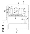
- FIG. 12 shows diagrammatically the construction of the battery pack 20 .
- the motor controller 24 comprises, inter alia, three main circuit components, namely a processor unit 36 with a digital signal processor 38 , a power stage 40 with the six power transistors Q 1 to Q 6 and an interruption switching unit 42 .
- the interruption switching unit 42 is connected to the battery 22 by two lines 32 and 34 .
- the interruption switching unit is connected to two of the three connection lines 44 of the electric motor 14 .
- the connection lines 44 are detachably connectable to the power pack 20 via three contacts.
- the interruption switching unit 42 and the processor unit 36 are connected, which is symbolized diagrammatically by the line 48 .
- the processor unit 36 is connected to the power stage 40 , which is symbolized diagrammatically by the line 50 .
- the interruption switching unit serves to separate the digital signal processor 38 of the processor unit 36 from the battery 22 when the power pack 20 is not connected to the electric motor 14 .
- the interruption switching unit 42 is connected via two lines 52 to two contact points 46 of the power pack 20 , which are connected to two connection lines 44 of the electric motor when the power pack 20 is pushed into the handle 18 of the housing 12 of the accumulator machine 10 . Only after connection of the power pack 20 to the electric motor 14 does the interruption switching unit 42 release the processor unit 36 , i.e., the latter is connected to the battery 22 .
- position sensors can, in principle, be used to determine an actual rotational speed of the electric motor 14 or to detect the rotor position. But, in the case of the accumulator machine 10 proposed in accordance with the invention, precisely such sensors are dispensed with. A very accurate determination of the rotational speed and the rotor position is, however, possible with identification methods. Luenberger observers or Kalman filters are examples of these. Since the digital signal processor 38 is a processor with a very rapid and high computing power, a rotational speed or a rotor position can be detected very precisely.
- the motor controller 24 is so designed that a rotational speed range of the electric motor 14 is divided into two partial ranges, namely, a lower rotational speed range 54 and an upper rotational speed range 56 , as shown diagrammatically in FIG. 13 . Furthermore, the motor controller 24 allows two different controlling and/or regulating methods for operating the electric motor 14 to be performed. This is, firstly, a space vector pulse width modulation (SVPWM) method, which is schematically designated by A in FIGS. 13 and 14 . Secondly, this is a conventional pulse width modulation (PWM) method, which is diagrammatically designated by B in FIGS. 13 and 14 .
- SVPWM space vector pulse width modulation
- PWM pulse width modulation
- the controlling and/or regulating method A could also be a controlling and/or regulating method in which an actual rotational speed of the electric motor 14 is determined by means of the rotational speed detection sensors and processed by the motor controller 24 .
- an actual rotational speed of the electric motor 14 is determined by detecting the CEMF (counterelectromotive force).
- the accumulator machine 10 is put into operation by an operator actuating the power/speed push-button 26 . Start/stop is designated by reference numeral 58 in FIG. 13 .
- the motor controller 24 performs the controlling and/or regulating method A until the switchover rotational speed D limit1 is reached. Once the switchover rotational speed D limit1 , is reached, the motor controller 24 automatically switches over to the controlling and/or regulating method B.
- the electric motor 14 is operated by the motor controller 24 in the controlling and/or regulating method B until the maximum rotational speed D max of the electric motor 14 is reached.
- the controlling and/or regulating method B is still maintained for rotational speeds of the electric motor 14 that are lower than the switchover rotational speed D limit1 until the switchover rotational speed D limit2 is reached. Only when the switchover rotational speed D limit2 is reached and fallen short of, does the motor controller 24 switch over to the controlling and/or regulating method A again. If the rotational speed requirement is increased again, a switchover to the controlling and/or regulating method B does, however, only take place again after the switchover rotational speed D limit1 is exceeded.
- the motor controller 24 can perform both the controlling and/or regulating method A and the controlling and/or regulating method B. Which method is carried out, will depend on whether the rotational speed requirement is increased from an actual rotational speed below the switchover rotational speed D limit2 or is lowered from above the switchover rotational speed D limit1 . All in all, this results in the hysteresis-like curve shown in FIG. 13 , on which it is possible to move around the overlapping range 60 in the counter-clockwise direction.
- the mode of operation of the motor controller 24 for switching over between the two controlling and/or regulating methods A and B will become apparent from FIG. 14 .
- the starting point is an electric motor 14 at a standstill.
- the motor controller 24 carries out the controlling and/or regulating method A.
- the actual rotational speed at the point in time t n is determined at periodic intervals. After determining the actual rotational speed at the point in time t n , it is inquired whether the actual rotational speed is less than the switchover rotational speed D limit1 . If the rotational speed is less than the switchover rotational speed D limit1 , it is then inquired whether the rotational speed is equal to 0. If this is the case, the motor controller 24 then stops operation of the electric motor 14 . If the actual rotational speed is less than the switchover rotational speed D limit1 , but greater than 0, the controlling and/or regulating method A is then carried out further.
- the motor controller 24 then switches over to the controlling and/or regulating method B.
- the actual rotational speed at the point in time t n+1 is kept on being determined at periodic intervals and subsequently compared with the previously determined actual rotational speed at the point in time t n . If the actual rotational speed at the point in time t n+1 is greater than the actual rotational speed at the point in time t n , the motor controller 24 then continues to carry out the controlling and/or regulating method B.
- the actual rotational speed at the point in time t n+1 is less than the actual rotational speed at the point in time t n
- the actual rotational speed is then compared with the switchover rotational speed D limit2 . If the actual rotational speed is greater than the switchover rotational speed D limit2 , the motor controller then continues to carry out the controlling and/or regulating method B. Otherwise the motor controller 24 automatically switches over to the controlling and/or regulating method A.
- the switchover between the two controlling and/or regulating methods A and B has, in particular, the advantage that a space vector pulse width modulation (SVPWM) method carried out at low rotational speeds, which shows undesirable damping effects at high rotational speeds, which result in motor losses and a negative influence on the efficiency of the accumulator machine 10 , need not be used at high rotational speeds.
- SVPWM space vector pulse width modulation
Landscapes
- Engineering & Computer Science (AREA)
- Power Engineering (AREA)
- Control Of Motors That Do Not Use Commutators (AREA)
- Surgical Instruments (AREA)
- Control Of Ac Motors In General (AREA)
Abstract
Description
Claims (27)
Priority Applications (1)
| Application Number | Priority Date | Filing Date | Title |
|---|---|---|---|
| US12/009,816 US7514890B2 (en) | 2004-07-30 | 2008-01-22 | Surgical machine and method for controlling and/or regulating a surgical machine |
Applications Claiming Priority (5)
| Application Number | Priority Date | Filing Date | Title |
|---|---|---|---|
| DE102004038415 | 2004-07-30 | ||
| DE102004038415A DE102004038415A1 (en) | 2004-07-30 | 2004-07-30 | Surgical machine and method for controlling and / or regulating a surgical machine |
| PCT/EP2005/007759 WO2006012990A1 (en) | 2004-07-30 | 2005-07-16 | Surgical machine and method for controlling and/or regulating one such surgical machine |
| US11/649,717 US7362062B2 (en) | 2004-07-30 | 2007-01-03 | Surgical machine and method for controlling and/or regulating a surgical machine |
| US12/009,816 US7514890B2 (en) | 2004-07-30 | 2008-01-22 | Surgical machine and method for controlling and/or regulating a surgical machine |
Related Parent Applications (1)
| Application Number | Title | Priority Date | Filing Date |
|---|---|---|---|
| US11/649,717 Continuation US7362062B2 (en) | 2004-07-30 | 2007-01-03 | Surgical machine and method for controlling and/or regulating a surgical machine |
Publications (2)
| Publication Number | Publication Date |
|---|---|
| US20080118234A1 US20080118234A1 (en) | 2008-05-22 |
| US7514890B2 true US7514890B2 (en) | 2009-04-07 |
Family
ID=35466492
Family Applications (2)
| Application Number | Title | Priority Date | Filing Date |
|---|---|---|---|
| US11/649,717 Active US7362062B2 (en) | 2004-07-30 | 2007-01-03 | Surgical machine and method for controlling and/or regulating a surgical machine |
| US12/009,816 Active US7514890B2 (en) | 2004-07-30 | 2008-01-22 | Surgical machine and method for controlling and/or regulating a surgical machine |
Family Applications Before (1)
| Application Number | Title | Priority Date | Filing Date |
|---|---|---|---|
| US11/649,717 Active US7362062B2 (en) | 2004-07-30 | 2007-01-03 | Surgical machine and method for controlling and/or regulating a surgical machine |
Country Status (7)
| Country | Link |
|---|---|
| US (2) | US7362062B2 (en) |
| EP (1) | EP1771941B1 (en) |
| JP (1) | JP4769249B2 (en) |
| AT (1) | ATE508527T1 (en) |
| DE (2) | DE102004038415A1 (en) |
| ES (1) | ES2362786T3 (en) |
| WO (1) | WO2006012990A1 (en) |
Cited By (12)
| Publication number | Priority date | Publication date | Assignee | Title |
|---|---|---|---|---|
| US20100264864A1 (en) * | 2009-04-08 | 2010-10-21 | Aesculap Ag | Surgical motor control device, surgical drive system and method for controlling a surgical drive unit |
| US8029510B2 (en) | 2005-04-16 | 2011-10-04 | Aesculap Ag | Surgical machine and method for controlling and/or regulating a surgical machine |
| US20130072952A1 (en) * | 2011-09-14 | 2013-03-21 | Olaf Storz | Medical handheld device and power unit |
| US20130221880A1 (en) * | 2012-02-29 | 2013-08-29 | Kabushiki Kaisha Toshiba | Motor driving circuit and motor apparatus |
| US8786233B2 (en) | 2011-04-27 | 2014-07-22 | Medtronic Xomed, Inc. | Electric ratchet for a powered screwdriver |
| US9265585B2 (en) | 2012-10-23 | 2016-02-23 | Covidien Lp | Surgical instrument with rapid post event detection |
| US11596400B2 (en) | 2017-06-09 | 2023-03-07 | Covidien Lp | Handheld electromechanical surgical system |
| US11744592B2 (en) | 2021-08-05 | 2023-09-05 | Covidien Lp | Handheld electromechanical stapler with tissue thickness detection |
| US11819208B2 (en) | 2021-08-05 | 2023-11-21 | Covidien Lp | Handheld electromechanical surgical device with strain gauge drift detection |
| US11857194B2 (en) | 2017-06-09 | 2024-01-02 | Covidien Lp | Handheld electromechanical surgical system |
| US11864768B2 (en) | 2017-06-09 | 2024-01-09 | Covidien Lp | Handheld electromechanical surgical system |
| US11877744B2 (en) | 2020-08-14 | 2024-01-23 | Covidien Lp | Low-cost powered stapler with end stop selection |
Families Citing this family (405)
| Publication number | Priority date | Publication date | Assignee | Title |
|---|---|---|---|---|
| US20070084897A1 (en) | 2003-05-20 | 2007-04-19 | Shelton Frederick E Iv | Articulating surgical stapling instrument incorporating a two-piece e-beam firing mechanism |
| US9060770B2 (en) | 2003-05-20 | 2015-06-23 | Ethicon Endo-Surgery, Inc. | Robotically-driven surgical instrument with E-beam driver |
| US9072535B2 (en) | 2011-05-27 | 2015-07-07 | Ethicon Endo-Surgery, Inc. | Surgical stapling instruments with rotatable staple deployment arrangements |
| US8215531B2 (en) | 2004-07-28 | 2012-07-10 | Ethicon Endo-Surgery, Inc. | Surgical stapling instrument having a medical substance dispenser |
| US11896225B2 (en) | 2004-07-28 | 2024-02-13 | Cilag Gmbh International | Staple cartridge comprising a pan |
| US11998198B2 (en) | 2004-07-28 | 2024-06-04 | Cilag Gmbh International | Surgical stapling instrument incorporating a two-piece E-beam firing mechanism |
| US7669746B2 (en) | 2005-08-31 | 2010-03-02 | Ethicon Endo-Surgery, Inc. | Staple cartridges for forming staples having differing formed staple heights |
| US9237891B2 (en) | 2005-08-31 | 2016-01-19 | Ethicon Endo-Surgery, Inc. | Robotically-controlled surgical stapling devices that produce formed staples having different lengths |
| US7934630B2 (en) | 2005-08-31 | 2011-05-03 | Ethicon Endo-Surgery, Inc. | Staple cartridges for forming staples having differing formed staple heights |
| US11484312B2 (en) | 2005-08-31 | 2022-11-01 | Cilag Gmbh International | Staple cartridge comprising a staple driver arrangement |
| US10159482B2 (en) | 2005-08-31 | 2018-12-25 | Ethicon Llc | Fastener cartridge assembly comprising a fixed anvil and different staple heights |
| US11246590B2 (en) | 2005-08-31 | 2022-02-15 | Cilag Gmbh International | Staple cartridge including staple drivers having different unfired heights |
| US20070106317A1 (en) | 2005-11-09 | 2007-05-10 | Shelton Frederick E Iv | Hydraulically and electrically actuated articulation joints for surgical instruments |
| US11278279B2 (en) | 2006-01-31 | 2022-03-22 | Cilag Gmbh International | Surgical instrument assembly |
| US8186555B2 (en) | 2006-01-31 | 2012-05-29 | Ethicon Endo-Surgery, Inc. | Motor-driven surgical cutting and fastening instrument with mechanical closure system |
| US11793518B2 (en) | 2006-01-31 | 2023-10-24 | Cilag Gmbh International | Powered surgical instruments with firing system lockout arrangements |
| US20110295295A1 (en) | 2006-01-31 | 2011-12-01 | Ethicon Endo-Surgery, Inc. | Robotically-controlled surgical instrument having recording capabilities |
| US7753904B2 (en) | 2006-01-31 | 2010-07-13 | Ethicon Endo-Surgery, Inc. | Endoscopic surgical instrument with a handle that can articulate with respect to the shaft |
| US7845537B2 (en) | 2006-01-31 | 2010-12-07 | Ethicon Endo-Surgery, Inc. | Surgical instrument having recording capabilities |
| US8820603B2 (en) | 2006-01-31 | 2014-09-02 | Ethicon Endo-Surgery, Inc. | Accessing data stored in a memory of a surgical instrument |
| US11224427B2 (en) | 2006-01-31 | 2022-01-18 | Cilag Gmbh International | Surgical stapling system including a console and retraction assembly |
| US20110024477A1 (en) | 2009-02-06 | 2011-02-03 | Hall Steven G | Driven Surgical Stapler Improvements |
| US20120292367A1 (en) | 2006-01-31 | 2012-11-22 | Ethicon Endo-Surgery, Inc. | Robotically-controlled end effector |
| US8708213B2 (en) | 2006-01-31 | 2014-04-29 | Ethicon Endo-Surgery, Inc. | Surgical instrument having a feedback system |
| US8992422B2 (en) | 2006-03-23 | 2015-03-31 | Ethicon Endo-Surgery, Inc. | Robotically-controlled endoscopic accessory channel |
| US8322455B2 (en) | 2006-06-27 | 2012-12-04 | Ethicon Endo-Surgery, Inc. | Manually driven surgical cutting and fastening instrument |
| US10568652B2 (en) | 2006-09-29 | 2020-02-25 | Ethicon Llc | Surgical staples having attached drivers of different heights and stapling instruments for deploying the same |
| US20080078802A1 (en) | 2006-09-29 | 2008-04-03 | Hess Christopher J | Surgical staples and stapling instruments |
| US11980366B2 (en) | 2006-10-03 | 2024-05-14 | Cilag Gmbh International | Surgical instrument |
| US8684253B2 (en) | 2007-01-10 | 2014-04-01 | Ethicon Endo-Surgery, Inc. | Surgical instrument with wireless communication between a control unit of a robotic system and remote sensor |
| US8840603B2 (en) | 2007-01-10 | 2014-09-23 | Ethicon Endo-Surgery, Inc. | Surgical instrument with wireless communication between control unit and sensor transponders |
| US8652120B2 (en) | 2007-01-10 | 2014-02-18 | Ethicon Endo-Surgery, Inc. | Surgical instrument with wireless communication between control unit and sensor transponders |
| US11291441B2 (en) | 2007-01-10 | 2022-04-05 | Cilag Gmbh International | Surgical instrument with wireless communication between control unit and remote sensor |
| US8827133B2 (en) | 2007-01-11 | 2014-09-09 | Ethicon Endo-Surgery, Inc. | Surgical stapling device having supports for a flexible drive mechanism |
| US11039836B2 (en) | 2007-01-11 | 2021-06-22 | Cilag Gmbh International | Staple cartridge for use with a surgical stapling instrument |
| US8590762B2 (en) | 2007-03-15 | 2013-11-26 | Ethicon Endo-Surgery, Inc. | Staple cartridge cavity configurations |
| US8893946B2 (en) | 2007-03-28 | 2014-11-25 | Ethicon Endo-Surgery, Inc. | Laparoscopic tissue thickness and clamp load measuring devices |
| US8931682B2 (en) | 2007-06-04 | 2015-01-13 | Ethicon Endo-Surgery, Inc. | Robotically-controlled shaft based rotary drive systems for surgical instruments |
| US11672531B2 (en) | 2007-06-04 | 2023-06-13 | Cilag Gmbh International | Rotary drive systems for surgical instruments |
| US7753245B2 (en) | 2007-06-22 | 2010-07-13 | Ethicon Endo-Surgery, Inc. | Surgical stapling instruments |
| US11849941B2 (en) | 2007-06-29 | 2023-12-26 | Cilag Gmbh International | Staple cartridge having staple cavities extending at a transverse angle relative to a longitudinal cartridge axis |
| US7866527B2 (en) | 2008-02-14 | 2011-01-11 | Ethicon Endo-Surgery, Inc. | Surgical stapling apparatus with interlockable firing system |
| US7819298B2 (en) | 2008-02-14 | 2010-10-26 | Ethicon Endo-Surgery, Inc. | Surgical stapling apparatus with control features operable with one hand |
| US8636736B2 (en) | 2008-02-14 | 2014-01-28 | Ethicon Endo-Surgery, Inc. | Motorized surgical cutting and fastening instrument |
| US9179912B2 (en) | 2008-02-14 | 2015-11-10 | Ethicon Endo-Surgery, Inc. | Robotically-controlled motorized surgical cutting and fastening instrument |
| RU2493788C2 (en) | 2008-02-14 | 2013-09-27 | Этикон Эндо-Серджери, Инк. | Surgical cutting and fixing instrument, which has radio-frequency electrodes |
| US8758391B2 (en) | 2008-02-14 | 2014-06-24 | Ethicon Endo-Surgery, Inc. | Interchangeable tools for surgical instruments |
| US8573465B2 (en) | 2008-02-14 | 2013-11-05 | Ethicon Endo-Surgery, Inc. | Robotically-controlled surgical end effector system with rotary actuated closure systems |
| US11986183B2 (en) | 2008-02-14 | 2024-05-21 | Cilag Gmbh International | Surgical cutting and fastening instrument comprising a plurality of sensors to measure an electrical parameter |
| US9585657B2 (en) | 2008-02-15 | 2017-03-07 | Ethicon Endo-Surgery, Llc | Actuator for releasing a layer of material from a surgical end effector |
| CN100557943C (en) | 2008-06-13 | 2009-11-04 | 株洲南车时代电气股份有限公司 | A kind of synchronous modulation method based on space vector |
| US9386983B2 (en) | 2008-09-23 | 2016-07-12 | Ethicon Endo-Surgery, Llc | Robotically-controlled motorized surgical instrument |
| US9005230B2 (en) | 2008-09-23 | 2015-04-14 | Ethicon Endo-Surgery, Inc. | Motorized surgical instrument |
| US8210411B2 (en) | 2008-09-23 | 2012-07-03 | Ethicon Endo-Surgery, Inc. | Motor-driven surgical cutting instrument |
| US11648005B2 (en) | 2008-09-23 | 2023-05-16 | Cilag Gmbh International | Robotically-controlled motorized surgical instrument with an end effector |
| US8608045B2 (en) | 2008-10-10 | 2013-12-17 | Ethicon Endo-Sugery, Inc. | Powered surgical cutting and stapling apparatus with manually retractable firing system |
| US8517239B2 (en) | 2009-02-05 | 2013-08-27 | Ethicon Endo-Surgery, Inc. | Surgical stapling instrument comprising a magnetic element driver |
| JP2012517287A (en) | 2009-02-06 | 2012-08-02 | エシコン・エンド−サージェリィ・インコーポレイテッド | Improvement of driven surgical stapler |
| US8444036B2 (en) | 2009-02-06 | 2013-05-21 | Ethicon Endo-Surgery, Inc. | Motor driven surgical fastener device with mechanisms for adjusting a tissue gap within the end effector |
| US8851354B2 (en) | 2009-12-24 | 2014-10-07 | Ethicon Endo-Surgery, Inc. | Surgical cutting instrument that analyzes tissue thickness |
| US8220688B2 (en) | 2009-12-24 | 2012-07-17 | Ethicon Endo-Surgery, Inc. | Motor-driven surgical cutting instrument with electric actuator directional control assembly |
| US8783543B2 (en) | 2010-07-30 | 2014-07-22 | Ethicon Endo-Surgery, Inc. | Tissue acquisition arrangements and methods for surgical stapling devices |
| US9629814B2 (en) | 2010-09-30 | 2017-04-25 | Ethicon Endo-Surgery, Llc | Tissue thickness compensator configured to redistribute compressive forces |
| US11849952B2 (en) | 2010-09-30 | 2023-12-26 | Cilag Gmbh International | Staple cartridge comprising staples positioned within a compressible portion thereof |
| US9788834B2 (en) | 2010-09-30 | 2017-10-17 | Ethicon Llc | Layer comprising deployable attachment members |
| US9241714B2 (en) | 2011-04-29 | 2016-01-26 | Ethicon Endo-Surgery, Inc. | Tissue thickness compensator and method for making the same |
| US11298125B2 (en) | 2010-09-30 | 2022-04-12 | Cilag Gmbh International | Tissue stapler having a thickness compensator |
| US8740038B2 (en) | 2010-09-30 | 2014-06-03 | Ethicon Endo-Surgery, Inc. | Staple cartridge comprising a releasable portion |
| US9364233B2 (en) | 2010-09-30 | 2016-06-14 | Ethicon Endo-Surgery, Llc | Tissue thickness compensators for circular surgical staplers |
| US10945731B2 (en) | 2010-09-30 | 2021-03-16 | Ethicon Llc | Tissue thickness compensator comprising controlled release and expansion |
| US11812965B2 (en) | 2010-09-30 | 2023-11-14 | Cilag Gmbh International | Layer of material for a surgical end effector |
| US9320523B2 (en) | 2012-03-28 | 2016-04-26 | Ethicon Endo-Surgery, Llc | Tissue thickness compensator comprising tissue ingrowth features |
| US8695866B2 (en) | 2010-10-01 | 2014-04-15 | Ethicon Endo-Surgery, Inc. | Surgical instrument having a power control circuit |
| CA2834649C (en) | 2011-04-29 | 2021-02-16 | Ethicon Endo-Surgery, Inc. | Staple cartridge comprising staples positioned within a compressible portion thereof |
| US11207064B2 (en) | 2011-05-27 | 2021-12-28 | Cilag Gmbh International | Automated end effector component reloading system for use with a robotic system |
| ITBO20110340A1 (en) * | 2011-06-13 | 2012-12-14 | Spal Automotive Srl | ELECTRIC DRIVE |
| US9044230B2 (en) | 2012-02-13 | 2015-06-02 | Ethicon Endo-Surgery, Inc. | Surgical cutting and fastening instrument with apparatus for determining cartridge and firing motion status |
| CN104334098B (en) | 2012-03-28 | 2017-03-22 | 伊西康内外科公司 | Tissue thickness compensator comprising capsules defining a low pressure environment |
| CN104379068B (en) | 2012-03-28 | 2017-09-22 | 伊西康内外科公司 | Holding device assembly including tissue thickness compensation part |
| RU2014143258A (en) | 2012-03-28 | 2016-05-20 | Этикон Эндо-Серджери, Инк. | FABRIC THICKNESS COMPENSATOR CONTAINING MANY LAYERS |
| US9101358B2 (en) | 2012-06-15 | 2015-08-11 | Ethicon Endo-Surgery, Inc. | Articulatable surgical instrument comprising a firing drive |
| US20140001234A1 (en) | 2012-06-28 | 2014-01-02 | Ethicon Endo-Surgery, Inc. | Coupling arrangements for attaching surgical end effectors to drive systems therefor |
| US11197671B2 (en) | 2012-06-28 | 2021-12-14 | Cilag Gmbh International | Stapling assembly comprising a lockout |
| US9282974B2 (en) | 2012-06-28 | 2016-03-15 | Ethicon Endo-Surgery, Llc | Empty clip cartridge lockout |
| CN104487005B (en) | 2012-06-28 | 2017-09-08 | 伊西康内外科公司 | Empty squeeze latching member |
| BR112014032776B1 (en) | 2012-06-28 | 2021-09-08 | Ethicon Endo-Surgery, Inc | SURGICAL INSTRUMENT SYSTEM AND SURGICAL KIT FOR USE WITH A SURGICAL INSTRUMENT SYSTEM |
| US9289256B2 (en) | 2012-06-28 | 2016-03-22 | Ethicon Endo-Surgery, Llc | Surgical end effectors having angled tissue-contacting surfaces |
| US20140001231A1 (en) | 2012-06-28 | 2014-01-02 | Ethicon Endo-Surgery, Inc. | Firing system lockout arrangements for surgical instruments |
| US9204879B2 (en) | 2012-06-28 | 2015-12-08 | Ethicon Endo-Surgery, Inc. | Flexible drive member |
| BR112015021082B1 (en) | 2013-03-01 | 2022-05-10 | Ethicon Endo-Surgery, Inc | surgical instrument |
| MX368026B (en) | 2013-03-01 | 2019-09-12 | Ethicon Endo Surgery Inc | Articulatable surgical instruments with conductive pathways for signal communication. |
| US9629629B2 (en) | 2013-03-14 | 2017-04-25 | Ethicon Endo-Surgey, LLC | Control systems for surgical instruments |
| US9332987B2 (en) | 2013-03-14 | 2016-05-10 | Ethicon Endo-Surgery, Llc | Control arrangements for a drive member of a surgical instrument |
| BR112015026109B1 (en) | 2013-04-16 | 2022-02-22 | Ethicon Endo-Surgery, Inc | surgical instrument |
| US10405857B2 (en) | 2013-04-16 | 2019-09-10 | Ethicon Llc | Powered linear surgical stapler |
| KR101304665B1 (en) | 2013-05-08 | 2013-09-06 | 영남대학교 산학협력단 | Method for controlling ac motor |
| US20150053737A1 (en) | 2013-08-23 | 2015-02-26 | Ethicon Endo-Surgery, Inc. | End effector detection systems for surgical instruments |
| CN106028966B (en) | 2013-08-23 | 2018-06-22 | 伊西康内外科有限责任公司 | For the firing member restoring device of powered surgical instrument |
| DE102014016852B4 (en) * | 2013-11-22 | 2017-06-08 | HKR Seuffer Automotive GmbH & Co. KG | Control system for an electric motor based on a pulsed control signal |
| DE102014001184B4 (en) | 2014-01-30 | 2018-08-23 | Otto Bock Healthcare Products Gmbh | Method for operating an electric motor |
| US9962161B2 (en) | 2014-02-12 | 2018-05-08 | Ethicon Llc | Deliverable surgical instrument |
| DE102014203388A1 (en) * | 2014-02-25 | 2015-08-27 | Zf Friedrichshafen Ag | Stabilizer for roll stabilization of a vehicle and method for operating such a stabilizer |
| BR112016021943B1 (en) | 2014-03-26 | 2022-06-14 | Ethicon Endo-Surgery, Llc | SURGICAL INSTRUMENT FOR USE BY AN OPERATOR IN A SURGICAL PROCEDURE |
| US10013049B2 (en) | 2014-03-26 | 2018-07-03 | Ethicon Llc | Power management through sleep options of segmented circuit and wake up control |
| US9820738B2 (en) | 2014-03-26 | 2017-11-21 | Ethicon Llc | Surgical instrument comprising interactive systems |
| US10327764B2 (en) | 2014-09-26 | 2019-06-25 | Ethicon Llc | Method for creating a flexible staple line |
| CN106456159B (en) | 2014-04-16 | 2019-03-08 | 伊西康内外科有限责任公司 | Fastener cartridge assembly and nail retainer lid arragement construction |
| CN106456158B (en) | 2014-04-16 | 2019-02-05 | 伊西康内外科有限责任公司 | Fastener cartridge including non-uniform fastener |
| US9844369B2 (en) | 2014-04-16 | 2017-12-19 | Ethicon Llc | Surgical end effectors with firing element monitoring arrangements |
| BR112016023698B1 (en) | 2014-04-16 | 2022-07-26 | Ethicon Endo-Surgery, Llc | FASTENER CARTRIDGE FOR USE WITH A SURGICAL INSTRUMENT |
| US20150297223A1 (en) | 2014-04-16 | 2015-10-22 | Ethicon Endo-Surgery, Inc. | Fastener cartridges including extensions having different configurations |
| US11311294B2 (en) | 2014-09-05 | 2022-04-26 | Cilag Gmbh International | Powered medical device including measurement of closure state of jaws |
| US9757128B2 (en) | 2014-09-05 | 2017-09-12 | Ethicon Llc | Multiple sensors with one sensor affecting a second sensor's output or interpretation |
| BR112017004361B1 (en) | 2014-09-05 | 2023-04-11 | Ethicon Llc | ELECTRONIC SYSTEM FOR A SURGICAL INSTRUMENT |
| US10105142B2 (en) | 2014-09-18 | 2018-10-23 | Ethicon Llc | Surgical stapler with plurality of cutting elements |
| CN107427300B (en) | 2014-09-26 | 2020-12-04 | 伊西康有限责任公司 | Surgical suture buttress and buttress material |
| US11523821B2 (en) | 2014-09-26 | 2022-12-13 | Cilag Gmbh International | Method for creating a flexible staple line |
| US10076325B2 (en) | 2014-10-13 | 2018-09-18 | Ethicon Llc | Surgical stapling apparatus comprising a tissue stop |
| US9924944B2 (en) | 2014-10-16 | 2018-03-27 | Ethicon Llc | Staple cartridge comprising an adjunct material |
| US10517594B2 (en) | 2014-10-29 | 2019-12-31 | Ethicon Llc | Cartridge assemblies for surgical staplers |
| US11141153B2 (en) | 2014-10-29 | 2021-10-12 | Cilag Gmbh International | Staple cartridges comprising driver arrangements |
| US9844376B2 (en) | 2014-11-06 | 2017-12-19 | Ethicon Llc | Staple cartridge comprising a releasable adjunct material |
| US10736636B2 (en) | 2014-12-10 | 2020-08-11 | Ethicon Llc | Articulatable surgical instrument system |
| US9987000B2 (en) | 2014-12-18 | 2018-06-05 | Ethicon Llc | Surgical instrument assembly comprising a flexible articulation system |
| US9844374B2 (en) | 2014-12-18 | 2017-12-19 | Ethicon Llc | Surgical instrument systems comprising an articulatable end effector and means for adjusting the firing stroke of a firing member |
| US9943309B2 (en) | 2014-12-18 | 2018-04-17 | Ethicon Llc | Surgical instruments with articulatable end effectors and movable firing beam support arrangements |
| US9844375B2 (en) | 2014-12-18 | 2017-12-19 | Ethicon Llc | Drive arrangements for articulatable surgical instruments |
| BR112017012996B1 (en) | 2014-12-18 | 2022-11-08 | Ethicon Llc | SURGICAL INSTRUMENT WITH AN ANvil WHICH IS SELECTIVELY MOVABLE ABOUT AN IMMOVABLE GEOMETRIC AXIS DIFFERENT FROM A STAPLE CARTRIDGE |
| US10085748B2 (en) | 2014-12-18 | 2018-10-02 | Ethicon Llc | Locking arrangements for detachable shaft assemblies with articulatable surgical end effectors |
| US11154301B2 (en) | 2015-02-27 | 2021-10-26 | Cilag Gmbh International | Modular stapling assembly |
| US10548504B2 (en) | 2015-03-06 | 2020-02-04 | Ethicon Llc | Overlaid multi sensor radio frequency (RF) electrode system to measure tissue compression |
| US10617412B2 (en) | 2015-03-06 | 2020-04-14 | Ethicon Llc | System for detecting the mis-insertion of a staple cartridge into a surgical stapler |
| US9808246B2 (en) | 2015-03-06 | 2017-11-07 | Ethicon Endo-Surgery, Llc | Method of operating a powered surgical instrument |
| US9993248B2 (en) | 2015-03-06 | 2018-06-12 | Ethicon Endo-Surgery, Llc | Smart sensors with local signal processing |
| US9924961B2 (en) | 2015-03-06 | 2018-03-27 | Ethicon Endo-Surgery, Llc | Interactive feedback system for powered surgical instruments |
| US10687806B2 (en) | 2015-03-06 | 2020-06-23 | Ethicon Llc | Adaptive tissue compression techniques to adjust closure rates for multiple tissue types |
| JP2020121162A (en) | 2015-03-06 | 2020-08-13 | エシコン エルエルシーEthicon LLC | Time dependent evaluation of sensor data to determine stability element, creep element and viscoelastic element of measurement |
| US10245033B2 (en) | 2015-03-06 | 2019-04-02 | Ethicon Llc | Surgical instrument comprising a lockable battery housing |
| US10441279B2 (en) | 2015-03-06 | 2019-10-15 | Ethicon Llc | Multiple level thresholds to modify operation of powered surgical instruments |
| US9901342B2 (en) | 2015-03-06 | 2018-02-27 | Ethicon Endo-Surgery, Llc | Signal and power communication system positioned on a rotatable shaft |
| US10390825B2 (en) | 2015-03-31 | 2019-08-27 | Ethicon Llc | Surgical instrument with progressive rotary drive systems |
| US10835249B2 (en) | 2015-08-17 | 2020-11-17 | Ethicon Llc | Implantable layers for a surgical instrument |
| US10238386B2 (en) | 2015-09-23 | 2019-03-26 | Ethicon Llc | Surgical stapler having motor control based on an electrical parameter related to a motor current |
| US10105139B2 (en) | 2015-09-23 | 2018-10-23 | Ethicon Llc | Surgical stapler having downstream current-based motor control |
| US10299878B2 (en) | 2015-09-25 | 2019-05-28 | Ethicon Llc | Implantable adjunct systems for determining adjunct skew |
| US10980539B2 (en) | 2015-09-30 | 2021-04-20 | Ethicon Llc | Implantable adjunct comprising bonded layers |
| US11890015B2 (en) | 2015-09-30 | 2024-02-06 | Cilag Gmbh International | Compressible adjunct with crossing spacer fibers |
| US10433846B2 (en) | 2015-09-30 | 2019-10-08 | Ethicon Llc | Compressible adjunct with crossing spacer fibers |
| US10478188B2 (en) | 2015-09-30 | 2019-11-19 | Ethicon Llc | Implantable layer comprising a constricted configuration |
| US10265068B2 (en) | 2015-12-30 | 2019-04-23 | Ethicon Llc | Surgical instruments with separable motors and motor control circuits |
| US10368865B2 (en) | 2015-12-30 | 2019-08-06 | Ethicon Llc | Mechanisms for compensating for drivetrain failure in powered surgical instruments |
| US10292704B2 (en) | 2015-12-30 | 2019-05-21 | Ethicon Llc | Mechanisms for compensating for battery pack failure in powered surgical instruments |
| US11213293B2 (en) | 2016-02-09 | 2022-01-04 | Cilag Gmbh International | Articulatable surgical instruments with single articulation link arrangements |
| US10245030B2 (en) | 2016-02-09 | 2019-04-02 | Ethicon Llc | Surgical instruments with tensioning arrangements for cable driven articulation systems |
| BR112018016098B1 (en) | 2016-02-09 | 2023-02-23 | Ethicon Llc | SURGICAL INSTRUMENT |
| US10448948B2 (en) | 2016-02-12 | 2019-10-22 | Ethicon Llc | Mechanisms for compensating for drivetrain failure in powered surgical instruments |
| US11224426B2 (en) | 2016-02-12 | 2022-01-18 | Cilag Gmbh International | Mechanisms for compensating for drivetrain failure in powered surgical instruments |
| US10314582B2 (en) | 2016-04-01 | 2019-06-11 | Ethicon Llc | Surgical instrument comprising a shifting mechanism |
| US10617413B2 (en) | 2016-04-01 | 2020-04-14 | Ethicon Llc | Closure system arrangements for surgical cutting and stapling devices with separate and distinct firing shafts |
| US10456137B2 (en) | 2016-04-15 | 2019-10-29 | Ethicon Llc | Staple formation detection mechanisms |
| US10492783B2 (en) | 2016-04-15 | 2019-12-03 | Ethicon, Llc | Surgical instrument with improved stop/start control during a firing motion |
| US11179150B2 (en) | 2016-04-15 | 2021-11-23 | Cilag Gmbh International | Systems and methods for controlling a surgical stapling and cutting instrument |
| US10335145B2 (en) | 2016-04-15 | 2019-07-02 | Ethicon Llc | Modular surgical instrument with configurable operating mode |
| US11607239B2 (en) | 2016-04-15 | 2023-03-21 | Cilag Gmbh International | Systems and methods for controlling a surgical stapling and cutting instrument |
| US10828028B2 (en) | 2016-04-15 | 2020-11-10 | Ethicon Llc | Surgical instrument with multiple program responses during a firing motion |
| US10357247B2 (en) | 2016-04-15 | 2019-07-23 | Ethicon Llc | Surgical instrument with multiple program responses during a firing motion |
| US10405859B2 (en) | 2016-04-15 | 2019-09-10 | Ethicon Llc | Surgical instrument with adjustable stop/start control during a firing motion |
| US10426467B2 (en) | 2016-04-15 | 2019-10-01 | Ethicon Llc | Surgical instrument with detection sensors |
| US20170296173A1 (en) | 2016-04-18 | 2017-10-19 | Ethicon Endo-Surgery, Llc | Method for operating a surgical instrument |
| US11317917B2 (en) | 2016-04-18 | 2022-05-03 | Cilag Gmbh International | Surgical stapling system comprising a lockable firing assembly |
| US10478181B2 (en) | 2016-04-18 | 2019-11-19 | Ethicon Llc | Cartridge lockout arrangements for rotary powered surgical cutting and stapling instruments |
| CH712828A1 (en) * | 2016-08-22 | 2018-02-28 | Lakeview Innvovation Ltd | Method for sensorless determination of the orientation of the rotor of an ironless PMSM motor. |
| US10426471B2 (en) * | 2016-12-21 | 2019-10-01 | Ethicon Llc | Surgical instrument with multiple failure response modes |
| US20180168615A1 (en) | 2016-12-21 | 2018-06-21 | Ethicon Endo-Surgery, Llc | Method of deforming staples from two different types of staple cartridges with the same surgical stapling instrument |
| US20180168618A1 (en) | 2016-12-21 | 2018-06-21 | Ethicon Endo-Surgery, Llc | Surgical stapling systems |
| US10588632B2 (en) | 2016-12-21 | 2020-03-17 | Ethicon Llc | Surgical end effectors and firing members thereof |
| US11191539B2 (en) | 2016-12-21 | 2021-12-07 | Cilag Gmbh International | Shaft assembly comprising a manually-operable retraction system for use with a motorized surgical instrument system |
| BR112019011947A2 (en) | 2016-12-21 | 2019-10-29 | Ethicon Llc | surgical stapling systems |
| US11134942B2 (en) | 2016-12-21 | 2021-10-05 | Cilag Gmbh International | Surgical stapling instruments and staple-forming anvils |
| US10736629B2 (en) | 2016-12-21 | 2020-08-11 | Ethicon Llc | Surgical tool assemblies with clutching arrangements for shifting between closure systems with closure stroke reduction features and articulation and firing systems |
| US10758229B2 (en) | 2016-12-21 | 2020-09-01 | Ethicon Llc | Surgical instrument comprising improved jaw control |
| US10667811B2 (en) | 2016-12-21 | 2020-06-02 | Ethicon Llc | Surgical stapling instruments and staple-forming anvils |
| JP7010956B2 (en) | 2016-12-21 | 2022-01-26 | エシコン エルエルシー | How to staple tissue |
| US10568624B2 (en) | 2016-12-21 | 2020-02-25 | Ethicon Llc | Surgical instruments with jaws that are pivotable about a fixed axis and include separate and distinct closure and firing systems |
| US11090048B2 (en) | 2016-12-21 | 2021-08-17 | Cilag Gmbh International | Method for resetting a fuse of a surgical instrument shaft |
| US10682138B2 (en) | 2016-12-21 | 2020-06-16 | Ethicon Llc | Bilaterally asymmetric staple forming pocket pairs |
| JP6983893B2 (en) | 2016-12-21 | 2021-12-17 | エシコン エルエルシーEthicon LLC | Lockout configuration for surgical end effectors and replaceable tool assemblies |
| US10485543B2 (en) | 2016-12-21 | 2019-11-26 | Ethicon Llc | Anvil having a knife slot width |
| US20180168609A1 (en) | 2016-12-21 | 2018-06-21 | Ethicon Endo-Surgery, Llc | Firing assembly comprising a fuse |
| US11419606B2 (en) | 2016-12-21 | 2022-08-23 | Cilag Gmbh International | Shaft assembly comprising a clutch configured to adapt the output of a rotary firing member to two different systems |
| MX2019007295A (en) | 2016-12-21 | 2019-10-15 | Ethicon Llc | Surgical instrument system comprising an end effector lockout and a firing assembly lockout. |
| US10758230B2 (en) | 2016-12-21 | 2020-09-01 | Ethicon Llc | Surgical instrument with primary and safety processors |
| DE102017205371A1 (en) * | 2017-03-29 | 2018-10-04 | Zf Friedrichshafen Ag | Method for sensorless determination of a position of a rotor of an electrical machine, control unit and control module |
| USD890784S1 (en) | 2017-06-20 | 2020-07-21 | Ethicon Llc | Display panel with changeable graphical user interface |
| US10881399B2 (en) | 2017-06-20 | 2021-01-05 | Ethicon Llc | Techniques for adaptive control of motor velocity of a surgical stapling and cutting instrument |
| US11071554B2 (en) | 2017-06-20 | 2021-07-27 | Cilag Gmbh International | Closed loop feedback control of motor velocity of a surgical stapling and cutting instrument based on magnitude of velocity error measurements |
| US11517325B2 (en) | 2017-06-20 | 2022-12-06 | Cilag Gmbh International | Closed loop feedback control of motor velocity of a surgical stapling and cutting instrument based on measured displacement distance traveled over a specified time interval |
| USD879808S1 (en) | 2017-06-20 | 2020-03-31 | Ethicon Llc | Display panel with graphical user interface |
| US10813639B2 (en) | 2017-06-20 | 2020-10-27 | Ethicon Llc | Closed loop feedback control of motor velocity of a surgical stapling and cutting instrument based on system conditions |
| US10646220B2 (en) | 2017-06-20 | 2020-05-12 | Ethicon Llc | Systems and methods for controlling displacement member velocity for a surgical instrument |
| US10779820B2 (en) | 2017-06-20 | 2020-09-22 | Ethicon Llc | Systems and methods for controlling motor speed according to user input for a surgical instrument |
| US11653914B2 (en) | 2017-06-20 | 2023-05-23 | Cilag Gmbh International | Systems and methods for controlling motor velocity of a surgical stapling and cutting instrument according to articulation angle of end effector |
| US10881396B2 (en) | 2017-06-20 | 2021-01-05 | Ethicon Llc | Surgical instrument with variable duration trigger arrangement |
| US11090046B2 (en) | 2017-06-20 | 2021-08-17 | Cilag Gmbh International | Systems and methods for controlling displacement member motion of a surgical stapling and cutting instrument |
| US10307170B2 (en) | 2017-06-20 | 2019-06-04 | Ethicon Llc | Method for closed loop control of motor velocity of a surgical stapling and cutting instrument |
| USD879809S1 (en) | 2017-06-20 | 2020-03-31 | Ethicon Llc | Display panel with changeable graphical user interface |
| US10888321B2 (en) | 2017-06-20 | 2021-01-12 | Ethicon Llc | Systems and methods for controlling velocity of a displacement member of a surgical stapling and cutting instrument |
| US10980537B2 (en) | 2017-06-20 | 2021-04-20 | Ethicon Llc | Closed loop feedback control of motor velocity of a surgical stapling and cutting instrument based on measured time over a specified number of shaft rotations |
| US11382638B2 (en) | 2017-06-20 | 2022-07-12 | Cilag Gmbh International | Closed loop feedback control of motor velocity of a surgical stapling and cutting instrument based on measured time over a specified displacement distance |
| US10624633B2 (en) | 2017-06-20 | 2020-04-21 | Ethicon Llc | Systems and methods for controlling motor velocity of a surgical stapling and cutting instrument |
| US10772629B2 (en) | 2017-06-27 | 2020-09-15 | Ethicon Llc | Surgical anvil arrangements |
| US20180368844A1 (en) | 2017-06-27 | 2018-12-27 | Ethicon Llc | Staple forming pocket arrangements |
| US10856869B2 (en) | 2017-06-27 | 2020-12-08 | Ethicon Llc | Surgical anvil arrangements |
| US11266405B2 (en) | 2017-06-27 | 2022-03-08 | Cilag Gmbh International | Surgical anvil manufacturing methods |
| US10993716B2 (en) | 2017-06-27 | 2021-05-04 | Ethicon Llc | Surgical anvil arrangements |
| US11324503B2 (en) | 2017-06-27 | 2022-05-10 | Cilag Gmbh International | Surgical firing member arrangements |
| EP3420947B1 (en) | 2017-06-28 | 2022-05-25 | Cilag GmbH International | Surgical instrument comprising selectively actuatable rotatable couplers |
| US11246592B2 (en) | 2017-06-28 | 2022-02-15 | Cilag Gmbh International | Surgical instrument comprising an articulation system lockable to a frame |
| US10716614B2 (en) | 2017-06-28 | 2020-07-21 | Ethicon Llc | Surgical shaft assemblies with slip ring assemblies with increased contact pressure |
| US11564686B2 (en) | 2017-06-28 | 2023-01-31 | Cilag Gmbh International | Surgical shaft assemblies with flexible interfaces |
| US11020114B2 (en) | 2017-06-28 | 2021-06-01 | Cilag Gmbh International | Surgical instruments with articulatable end effector with axially shortened articulation joint configurations |
| US11678880B2 (en) | 2017-06-28 | 2023-06-20 | Cilag Gmbh International | Surgical instrument comprising a shaft including a housing arrangement |
| US11259805B2 (en) | 2017-06-28 | 2022-03-01 | Cilag Gmbh International | Surgical instrument comprising firing member supports |
| US10765427B2 (en) | 2017-06-28 | 2020-09-08 | Ethicon Llc | Method for articulating a surgical instrument |
| USD906355S1 (en) | 2017-06-28 | 2020-12-29 | Ethicon Llc | Display screen or portion thereof with a graphical user interface for a surgical instrument |
| US10903685B2 (en) | 2017-06-28 | 2021-01-26 | Ethicon Llc | Surgical shaft assemblies with slip ring assemblies forming capacitive channels |
| USD869655S1 (en) | 2017-06-28 | 2019-12-10 | Ethicon Llc | Surgical fastener cartridge |
| US11007022B2 (en) | 2017-06-29 | 2021-05-18 | Ethicon Llc | Closed loop velocity control techniques based on sensed tissue parameters for robotic surgical instrument |
| US10898183B2 (en) | 2017-06-29 | 2021-01-26 | Ethicon Llc | Robotic surgical instrument with closed loop feedback techniques for advancement of closure member during firing |
| US10932772B2 (en) | 2017-06-29 | 2021-03-02 | Ethicon Llc | Methods for closed loop velocity control for robotic surgical instrument |
| US10398434B2 (en) | 2017-06-29 | 2019-09-03 | Ethicon Llc | Closed loop velocity control of closure member for robotic surgical instrument |
| US11944300B2 (en) | 2017-08-03 | 2024-04-02 | Cilag Gmbh International | Method for operating a surgical system bailout |
| US11304695B2 (en) | 2017-08-03 | 2022-04-19 | Cilag Gmbh International | Surgical system shaft interconnection |
| US11471155B2 (en) | 2017-08-03 | 2022-10-18 | Cilag Gmbh International | Surgical system bailout |
| US11974742B2 (en) | 2017-08-03 | 2024-05-07 | Cilag Gmbh International | Surgical system comprising an articulation bailout |
| WO2019052650A1 (en) * | 2017-09-15 | 2019-03-21 | HELLA GmbH & Co. KGaA | Method for monitoring a field oriented control of an electric motor and electric motor |
| USD917500S1 (en) | 2017-09-29 | 2021-04-27 | Ethicon Llc | Display screen or portion thereof with graphical user interface |
| US10796471B2 (en) | 2017-09-29 | 2020-10-06 | Ethicon Llc | Systems and methods of displaying a knife position for a surgical instrument |
| US10729501B2 (en) | 2017-09-29 | 2020-08-04 | Ethicon Llc | Systems and methods for language selection of a surgical instrument |
| USD907647S1 (en) | 2017-09-29 | 2021-01-12 | Ethicon Llc | Display screen or portion thereof with animated graphical user interface |
| US10743872B2 (en) | 2017-09-29 | 2020-08-18 | Ethicon Llc | System and methods for controlling a display of a surgical instrument |
| USD907648S1 (en) | 2017-09-29 | 2021-01-12 | Ethicon Llc | Display screen or portion thereof with animated graphical user interface |
| US10765429B2 (en) | 2017-09-29 | 2020-09-08 | Ethicon Llc | Systems and methods for providing alerts according to the operational state of a surgical instrument |
| US11399829B2 (en) | 2017-09-29 | 2022-08-02 | Cilag Gmbh International | Systems and methods of initiating a power shutdown mode for a surgical instrument |
| US11090075B2 (en) | 2017-10-30 | 2021-08-17 | Cilag Gmbh International | Articulation features for surgical end effector |
| US11134944B2 (en) | 2017-10-30 | 2021-10-05 | Cilag Gmbh International | Surgical stapler knife motion controls |
| US10842490B2 (en) | 2017-10-31 | 2020-11-24 | Ethicon Llc | Cartridge body design with force reduction based on firing completion |
| US10779903B2 (en) | 2017-10-31 | 2020-09-22 | Ethicon Llc | Positive shaft rotation lock activated by jaw closure |
| US10779825B2 (en) | 2017-12-15 | 2020-09-22 | Ethicon Llc | Adapters with end effector position sensing and control arrangements for use in connection with electromechanical surgical instruments |
| US10869666B2 (en) | 2017-12-15 | 2020-12-22 | Ethicon Llc | Adapters with control systems for controlling multiple motors of an electromechanical surgical instrument |
| US11071543B2 (en) | 2017-12-15 | 2021-07-27 | Cilag Gmbh International | Surgical end effectors with clamping assemblies configured to increase jaw aperture ranges |
| US11033267B2 (en) | 2017-12-15 | 2021-06-15 | Ethicon Llc | Systems and methods of controlling a clamping member firing rate of a surgical instrument |
| US10743875B2 (en) | 2017-12-15 | 2020-08-18 | Ethicon Llc | Surgical end effectors with jaw stiffener arrangements configured to permit monitoring of firing member |
| US10828033B2 (en) | 2017-12-15 | 2020-11-10 | Ethicon Llc | Handheld electromechanical surgical instruments with improved motor control arrangements for positioning components of an adapter coupled thereto |
| US11197670B2 (en) | 2017-12-15 | 2021-12-14 | Cilag Gmbh International | Surgical end effectors with pivotal jaws configured to touch at their respective distal ends when fully closed |
| US11006955B2 (en) | 2017-12-15 | 2021-05-18 | Ethicon Llc | End effectors with positive jaw opening features for use with adapters for electromechanical surgical instruments |
| US10743874B2 (en) | 2017-12-15 | 2020-08-18 | Ethicon Llc | Sealed adapters for use with electromechanical surgical instruments |
| US10687813B2 (en) | 2017-12-15 | 2020-06-23 | Ethicon Llc | Adapters with firing stroke sensing arrangements for use in connection with electromechanical surgical instruments |
| US10779826B2 (en) | 2017-12-15 | 2020-09-22 | Ethicon Llc | Methods of operating surgical end effectors |
| US10966718B2 (en) | 2017-12-15 | 2021-04-06 | Ethicon Llc | Dynamic clamping assemblies with improved wear characteristics for use in connection with electromechanical surgical instruments |
| US10729509B2 (en) | 2017-12-19 | 2020-08-04 | Ethicon Llc | Surgical instrument comprising closure and firing locking mechanism |
| US11020112B2 (en) | 2017-12-19 | 2021-06-01 | Ethicon Llc | Surgical tools configured for interchangeable use with different controller interfaces |
| US11045270B2 (en) | 2017-12-19 | 2021-06-29 | Cilag Gmbh International | Robotic attachment comprising exterior drive actuator |
| US10716565B2 (en) | 2017-12-19 | 2020-07-21 | Ethicon Llc | Surgical instruments with dual articulation drivers |
| USD910847S1 (en) | 2017-12-19 | 2021-02-16 | Ethicon Llc | Surgical instrument assembly |
| US10835330B2 (en) | 2017-12-19 | 2020-11-17 | Ethicon Llc | Method for determining the position of a rotatable jaw of a surgical instrument attachment assembly |
| US20190192147A1 (en) | 2017-12-21 | 2019-06-27 | Ethicon Llc | Surgical instrument comprising an articulatable distal head |
| US11076853B2 (en) | 2017-12-21 | 2021-08-03 | Cilag Gmbh International | Systems and methods of displaying a knife position during transection for a surgical instrument |
| US11311290B2 (en) | 2017-12-21 | 2022-04-26 | Cilag Gmbh International | Surgical instrument comprising an end effector dampener |
| US11129680B2 (en) | 2017-12-21 | 2021-09-28 | Cilag Gmbh International | Surgical instrument comprising a projector |
| US11207065B2 (en) | 2018-08-20 | 2021-12-28 | Cilag Gmbh International | Method for fabricating surgical stapler anvils |
| US10779821B2 (en) | 2018-08-20 | 2020-09-22 | Ethicon Llc | Surgical stapler anvils with tissue stop features configured to avoid tissue pinch |
| USD914878S1 (en) | 2018-08-20 | 2021-03-30 | Ethicon Llc | Surgical instrument anvil |
| US11253256B2 (en) | 2018-08-20 | 2022-02-22 | Cilag Gmbh International | Articulatable motor powered surgical instruments with dedicated articulation motor arrangements |
| US11039834B2 (en) | 2018-08-20 | 2021-06-22 | Cilag Gmbh International | Surgical stapler anvils with staple directing protrusions and tissue stability features |
| US11324501B2 (en) | 2018-08-20 | 2022-05-10 | Cilag Gmbh International | Surgical stapling devices with improved closure members |
| US10856870B2 (en) | 2018-08-20 | 2020-12-08 | Ethicon Llc | Switching arrangements for motor powered articulatable surgical instruments |
| US11083458B2 (en) | 2018-08-20 | 2021-08-10 | Cilag Gmbh International | Powered surgical instruments with clutching arrangements to convert linear drive motions to rotary drive motions |
| US11045192B2 (en) | 2018-08-20 | 2021-06-29 | Cilag Gmbh International | Fabricating techniques for surgical stapler anvils |
| US10912559B2 (en) | 2018-08-20 | 2021-02-09 | Ethicon Llc | Reinforced deformable anvil tip for surgical stapler anvil |
| US10842492B2 (en) | 2018-08-20 | 2020-11-24 | Ethicon Llc | Powered articulatable surgical instruments with clutching and locking arrangements for linking an articulation drive system to a firing drive system |
| US11291440B2 (en) | 2018-08-20 | 2022-04-05 | Cilag Gmbh International | Method for operating a powered articulatable surgical instrument |
| US11147553B2 (en) | 2019-03-25 | 2021-10-19 | Cilag Gmbh International | Firing drive arrangements for surgical systems |
| US11147551B2 (en) | 2019-03-25 | 2021-10-19 | Cilag Gmbh International | Firing drive arrangements for surgical systems |
| US11696761B2 (en) | 2019-03-25 | 2023-07-11 | Cilag Gmbh International | Firing drive arrangements for surgical systems |
| US11172929B2 (en) | 2019-03-25 | 2021-11-16 | Cilag Gmbh International | Articulation drive arrangements for surgical systems |
| US11452528B2 (en) | 2019-04-30 | 2022-09-27 | Cilag Gmbh International | Articulation actuators for a surgical instrument |
| US11471157B2 (en) | 2019-04-30 | 2022-10-18 | Cilag Gmbh International | Articulation control mapping for a surgical instrument |
| US11253254B2 (en) | 2019-04-30 | 2022-02-22 | Cilag Gmbh International | Shaft rotation actuator on a surgical instrument |
| US11426251B2 (en) | 2019-04-30 | 2022-08-30 | Cilag Gmbh International | Articulation directional lights on a surgical instrument |
| US11648009B2 (en) | 2019-04-30 | 2023-05-16 | Cilag Gmbh International | Rotatable jaw tip for a surgical instrument |
| US11903581B2 (en) | 2019-04-30 | 2024-02-20 | Cilag Gmbh International | Methods for stapling tissue using a surgical instrument |
| US11432816B2 (en) | 2019-04-30 | 2022-09-06 | Cilag Gmbh International | Articulation pin for a surgical instrument |
| US11426167B2 (en) | 2019-06-28 | 2022-08-30 | Cilag Gmbh International | Mechanisms for proper anvil attachment surgical stapling head assembly |
| US11464601B2 (en) | 2019-06-28 | 2022-10-11 | Cilag Gmbh International | Surgical instrument comprising an RFID system for tracking a movable component |
| US11399837B2 (en) | 2019-06-28 | 2022-08-02 | Cilag Gmbh International | Mechanisms for motor control adjustments of a motorized surgical instrument |
| US11497492B2 (en) | 2019-06-28 | 2022-11-15 | Cilag Gmbh International | Surgical instrument including an articulation lock |
| US11553971B2 (en) | 2019-06-28 | 2023-01-17 | Cilag Gmbh International | Surgical RFID assemblies for display and communication |
| US11219455B2 (en) | 2019-06-28 | 2022-01-11 | Cilag Gmbh International | Surgical instrument including a lockout key |
| US11523822B2 (en) | 2019-06-28 | 2022-12-13 | Cilag Gmbh International | Battery pack including a circuit interrupter |
| US11478241B2 (en) | 2019-06-28 | 2022-10-25 | Cilag Gmbh International | Staple cartridge including projections |
| US12004740B2 (en) | 2019-06-28 | 2024-06-11 | Cilag Gmbh International | Surgical stapling system having an information decryption protocol |
| US11241235B2 (en) | 2019-06-28 | 2022-02-08 | Cilag Gmbh International | Method of using multiple RFID chips with a surgical assembly |
| US11298127B2 (en) | 2019-06-28 | 2022-04-12 | Cilag GmbH Interational | Surgical stapling system having a lockout mechanism for an incompatible cartridge |
| US11684434B2 (en) | 2019-06-28 | 2023-06-27 | Cilag Gmbh International | Surgical RFID assemblies for instrument operational setting control |
| US11638587B2 (en) | 2019-06-28 | 2023-05-02 | Cilag Gmbh International | RFID identification systems for surgical instruments |
| US11771419B2 (en) | 2019-06-28 | 2023-10-03 | Cilag Gmbh International | Packaging for a replaceable component of a surgical stapling system |
| US11627959B2 (en) | 2019-06-28 | 2023-04-18 | Cilag Gmbh International | Surgical instruments including manual and powered system lockouts |
| US11291451B2 (en) | 2019-06-28 | 2022-04-05 | Cilag Gmbh International | Surgical instrument with battery compatibility verification functionality |
| US11298132B2 (en) | 2019-06-28 | 2022-04-12 | Cilag GmbH Inlernational | Staple cartridge including a honeycomb extension |
| US11051807B2 (en) | 2019-06-28 | 2021-07-06 | Cilag Gmbh International | Packaging assembly including a particulate trap |
| US11246678B2 (en) | 2019-06-28 | 2022-02-15 | Cilag Gmbh International | Surgical stapling system having a frangible RFID tag |
| US11376098B2 (en) | 2019-06-28 | 2022-07-05 | Cilag Gmbh International | Surgical instrument system comprising an RFID system |
| US11660163B2 (en) | 2019-06-28 | 2023-05-30 | Cilag Gmbh International | Surgical system with RFID tags for updating motor assembly parameters |
| US11224497B2 (en) | 2019-06-28 | 2022-01-18 | Cilag Gmbh International | Surgical systems with multiple RFID tags |
| US11259803B2 (en) | 2019-06-28 | 2022-03-01 | Cilag Gmbh International | Surgical stapling system having an information encryption protocol |
| US12035913B2 (en) | 2019-12-19 | 2024-07-16 | Cilag Gmbh International | Staple cartridge comprising a deployable knife |
| US11304696B2 (en) | 2019-12-19 | 2022-04-19 | Cilag Gmbh International | Surgical instrument comprising a powered articulation system |
| US11446029B2 (en) | 2019-12-19 | 2022-09-20 | Cilag Gmbh International | Staple cartridge comprising projections extending from a curved deck surface |
| US11911032B2 (en) | 2019-12-19 | 2024-02-27 | Cilag Gmbh International | Staple cartridge comprising a seating cam |
| US11529139B2 (en) | 2019-12-19 | 2022-12-20 | Cilag Gmbh International | Motor driven surgical instrument |
| US11701111B2 (en) | 2019-12-19 | 2023-07-18 | Cilag Gmbh International | Method for operating a surgical stapling instrument |
| US11464512B2 (en) | 2019-12-19 | 2022-10-11 | Cilag Gmbh International | Staple cartridge comprising a curved deck surface |
| US11234698B2 (en) | 2019-12-19 | 2022-02-01 | Cilag Gmbh International | Stapling system comprising a clamp lockout and a firing lockout |
| US11844520B2 (en) | 2019-12-19 | 2023-12-19 | Cilag Gmbh International | Staple cartridge comprising driver retention members |
| US11504122B2 (en) | 2019-12-19 | 2022-11-22 | Cilag Gmbh International | Surgical instrument comprising a nested firing member |
| US11559304B2 (en) | 2019-12-19 | 2023-01-24 | Cilag Gmbh International | Surgical instrument comprising a rapid closure mechanism |
| US11529137B2 (en) | 2019-12-19 | 2022-12-20 | Cilag Gmbh International | Staple cartridge comprising driver retention members |
| US11291447B2 (en) | 2019-12-19 | 2022-04-05 | Cilag Gmbh International | Stapling instrument comprising independent jaw closing and staple firing systems |
| US11931033B2 (en) | 2019-12-19 | 2024-03-19 | Cilag Gmbh International | Staple cartridge comprising a latch lockout |
| US11576672B2 (en) | 2019-12-19 | 2023-02-14 | Cilag Gmbh International | Surgical instrument comprising a closure system including a closure member and an opening member driven by a drive screw |
| US11607219B2 (en) | 2019-12-19 | 2023-03-21 | Cilag Gmbh International | Staple cartridge comprising a detachable tissue cutting knife |
| DE102020109069A1 (en) | 2020-04-01 | 2021-10-07 | Aesculap Ag | Smart drill with data monitoring / smart medical electric drive instrument with data monitoring |
| DE102020109932A1 (en) | 2020-04-09 | 2021-10-14 | Aesculap Ag | Adaptive tool operation |
| USD976401S1 (en) | 2020-06-02 | 2023-01-24 | Cilag Gmbh International | Staple cartridge |
| USD975850S1 (en) | 2020-06-02 | 2023-01-17 | Cilag Gmbh International | Staple cartridge |
| USD975278S1 (en) | 2020-06-02 | 2023-01-10 | Cilag Gmbh International | Staple cartridge |
| USD967421S1 (en) | 2020-06-02 | 2022-10-18 | Cilag Gmbh International | Staple cartridge |
| USD966512S1 (en) | 2020-06-02 | 2022-10-11 | Cilag Gmbh International | Staple cartridge |
| USD974560S1 (en) | 2020-06-02 | 2023-01-03 | Cilag Gmbh International | Staple cartridge |
| USD975851S1 (en) | 2020-06-02 | 2023-01-17 | Cilag Gmbh International | Staple cartridge |
| TWI759774B (en) * | 2020-06-20 | 2022-04-01 | 國立成功大學 | Electrical system and control method applied for motor drive |
| US20220031350A1 (en) | 2020-07-28 | 2022-02-03 | Cilag Gmbh International | Surgical instruments with double pivot articulation joint arrangements |
| US11398785B2 (en) * | 2020-09-24 | 2022-07-26 | Infineon Technologies Austria Ag | Position detection and monitoring |
| US11896217B2 (en) | 2020-10-29 | 2024-02-13 | Cilag Gmbh International | Surgical instrument comprising an articulation lock |
| US11517390B2 (en) | 2020-10-29 | 2022-12-06 | Cilag Gmbh International | Surgical instrument comprising a limited travel switch |
| US11452526B2 (en) | 2020-10-29 | 2022-09-27 | Cilag Gmbh International | Surgical instrument comprising a staged voltage regulation start-up system |
| US12053175B2 (en) | 2020-10-29 | 2024-08-06 | Cilag Gmbh International | Surgical instrument comprising a stowed closure actuator stop |
| US11931025B2 (en) | 2020-10-29 | 2024-03-19 | Cilag Gmbh International | Surgical instrument comprising a releasable closure drive lock |
| US11779330B2 (en) | 2020-10-29 | 2023-10-10 | Cilag Gmbh International | Surgical instrument comprising a jaw alignment system |
| US11844518B2 (en) | 2020-10-29 | 2023-12-19 | Cilag Gmbh International | Method for operating a surgical instrument |
| US11617577B2 (en) | 2020-10-29 | 2023-04-04 | Cilag Gmbh International | Surgical instrument comprising a sensor configured to sense whether an articulation drive of the surgical instrument is actuatable |
| USD980425S1 (en) | 2020-10-29 | 2023-03-07 | Cilag Gmbh International | Surgical instrument assembly |
| US11534259B2 (en) | 2020-10-29 | 2022-12-27 | Cilag Gmbh International | Surgical instrument comprising an articulation indicator |
| US11717289B2 (en) | 2020-10-29 | 2023-08-08 | Cilag Gmbh International | Surgical instrument comprising an indicator which indicates that an articulation drive is actuatable |
| USD1013170S1 (en) | 2020-10-29 | 2024-01-30 | Cilag Gmbh International | Surgical instrument assembly |
| US11944296B2 (en) | 2020-12-02 | 2024-04-02 | Cilag Gmbh International | Powered surgical instruments with external connectors |
| US11849943B2 (en) | 2020-12-02 | 2023-12-26 | Cilag Gmbh International | Surgical instrument with cartridge release mechanisms |
| US11890010B2 (en) | 2020-12-02 | 2024-02-06 | Cllag GmbH International | Dual-sided reinforced reload for surgical instruments |
| US11737751B2 (en) | 2020-12-02 | 2023-08-29 | Cilag Gmbh International | Devices and methods of managing energy dissipated within sterile barriers of surgical instrument housings |
| US11744581B2 (en) | 2020-12-02 | 2023-09-05 | Cilag Gmbh International | Powered surgical instruments with multi-phase tissue treatment |
| US11678882B2 (en) | 2020-12-02 | 2023-06-20 | Cilag Gmbh International | Surgical instruments with interactive features to remedy incidental sled movements |
| US11653915B2 (en) | 2020-12-02 | 2023-05-23 | Cilag Gmbh International | Surgical instruments with sled location detection and adjustment features |
| US11653920B2 (en) | 2020-12-02 | 2023-05-23 | Cilag Gmbh International | Powered surgical instruments with communication interfaces through sterile barrier |
| US11627960B2 (en) | 2020-12-02 | 2023-04-18 | Cilag Gmbh International | Powered surgical instruments with smart reload with separately attachable exteriorly mounted wiring connections |
| US12108951B2 (en) | 2021-02-26 | 2024-10-08 | Cilag Gmbh International | Staple cartridge comprising a sensing array and a temperature control system |
| US11723657B2 (en) | 2021-02-26 | 2023-08-15 | Cilag Gmbh International | Adjustable communication based on available bandwidth and power capacity |
| US11730473B2 (en) | 2021-02-26 | 2023-08-22 | Cilag Gmbh International | Monitoring of manufacturing life-cycle |
| US11925349B2 (en) | 2021-02-26 | 2024-03-12 | Cilag Gmbh International | Adjustment to transfer parameters to improve available power |
| US11701113B2 (en) | 2021-02-26 | 2023-07-18 | Cilag Gmbh International | Stapling instrument comprising a separate power antenna and a data transfer antenna |
| US11793514B2 (en) | 2021-02-26 | 2023-10-24 | Cilag Gmbh International | Staple cartridge comprising sensor array which may be embedded in cartridge body |
| US11950779B2 (en) | 2021-02-26 | 2024-04-09 | Cilag Gmbh International | Method of powering and communicating with a staple cartridge |
| US11950777B2 (en) | 2021-02-26 | 2024-04-09 | Cilag Gmbh International | Staple cartridge comprising an information access control system |
| US11751869B2 (en) | 2021-02-26 | 2023-09-12 | Cilag Gmbh International | Monitoring of multiple sensors over time to detect moving characteristics of tissue |
| US11980362B2 (en) | 2021-02-26 | 2024-05-14 | Cilag Gmbh International | Surgical instrument system comprising a power transfer coil |
| US11696757B2 (en) | 2021-02-26 | 2023-07-11 | Cilag Gmbh International | Monitoring of internal systems to detect and track cartridge motion status |
| US11749877B2 (en) | 2021-02-26 | 2023-09-05 | Cilag Gmbh International | Stapling instrument comprising a signal antenna |
| US11744583B2 (en) | 2021-02-26 | 2023-09-05 | Cilag Gmbh International | Distal communication array to tune frequency of RF systems |
| US11812964B2 (en) | 2021-02-26 | 2023-11-14 | Cilag Gmbh International | Staple cartridge comprising a power management circuit |
| US11737749B2 (en) | 2021-03-22 | 2023-08-29 | Cilag Gmbh International | Surgical stapling instrument comprising a retraction system |
| US11759202B2 (en) | 2021-03-22 | 2023-09-19 | Cilag Gmbh International | Staple cartridge comprising an implantable layer |
| US11806011B2 (en) | 2021-03-22 | 2023-11-07 | Cilag Gmbh International | Stapling instrument comprising tissue compression systems |
| US11826012B2 (en) | 2021-03-22 | 2023-11-28 | Cilag Gmbh International | Stapling instrument comprising a pulsed motor-driven firing rack |
| US11717291B2 (en) | 2021-03-22 | 2023-08-08 | Cilag Gmbh International | Staple cartridge comprising staples configured to apply different tissue compression |
| US11723658B2 (en) | 2021-03-22 | 2023-08-15 | Cilag Gmbh International | Staple cartridge comprising a firing lockout |
| US11826042B2 (en) | 2021-03-22 | 2023-11-28 | Cilag Gmbh International | Surgical instrument comprising a firing drive including a selectable leverage mechanism |
| US11744603B2 (en) | 2021-03-24 | 2023-09-05 | Cilag Gmbh International | Multi-axis pivot joints for surgical instruments and methods for manufacturing same |
| US11849945B2 (en) | 2021-03-24 | 2023-12-26 | Cilag Gmbh International | Rotary-driven surgical stapling assembly comprising eccentrically driven firing member |
| US12102323B2 (en) | 2021-03-24 | 2024-10-01 | Cilag Gmbh International | Rotary-driven surgical stapling assembly comprising a floatable component |
| US11786239B2 (en) | 2021-03-24 | 2023-10-17 | Cilag Gmbh International | Surgical instrument articulation joint arrangements comprising multiple moving linkage features |
| US11857183B2 (en) | 2021-03-24 | 2024-01-02 | Cilag Gmbh International | Stapling assembly components having metal substrates and plastic bodies |
| US11903582B2 (en) | 2021-03-24 | 2024-02-20 | Cilag Gmbh International | Leveraging surfaces for cartridge installation |
| US11896219B2 (en) | 2021-03-24 | 2024-02-13 | Cilag Gmbh International | Mating features between drivers and underside of a cartridge deck |
| US11944336B2 (en) | 2021-03-24 | 2024-04-02 | Cilag Gmbh International | Joint arrangements for multi-planar alignment and support of operational drive shafts in articulatable surgical instruments |
| US11896218B2 (en) | 2021-03-24 | 2024-02-13 | Cilag Gmbh International | Method of using a powered stapling device |
| US11849944B2 (en) | 2021-03-24 | 2023-12-26 | Cilag Gmbh International | Drivers for fastener cartridge assemblies having rotary drive screws |
| US11793516B2 (en) | 2021-03-24 | 2023-10-24 | Cilag Gmbh International | Surgical staple cartridge comprising longitudinal support beam |
| US11786243B2 (en) | 2021-03-24 | 2023-10-17 | Cilag Gmbh International | Firing members having flexible portions for adapting to a load during a surgical firing stroke |
| US11832816B2 (en) | 2021-03-24 | 2023-12-05 | Cilag Gmbh International | Surgical stapling assembly comprising nonplanar staples and planar staples |
| US11998201B2 (en) | 2021-05-28 | 2024-06-04 | Cilag CmbH International | Stapling instrument comprising a firing lockout |
| US11877745B2 (en) | 2021-10-18 | 2024-01-23 | Cilag Gmbh International | Surgical stapling assembly having longitudinally-repeating staple leg clusters |
| US11980363B2 (en) | 2021-10-18 | 2024-05-14 | Cilag Gmbh International | Row-to-row staple array variations |
| US11957337B2 (en) | 2021-10-18 | 2024-04-16 | Cilag Gmbh International | Surgical stapling assembly with offset ramped drive surfaces |
| US11937816B2 (en) | 2021-10-28 | 2024-03-26 | Cilag Gmbh International | Electrical lead arrangements for surgical instruments |
| US12089841B2 (en) | 2021-10-28 | 2024-09-17 | Cilag CmbH International | Staple cartridge identification systems |
Citations (25)
| Publication number | Priority date | Publication date | Assignee | Title |
|---|---|---|---|---|
| US2244683A (en) | 1938-06-11 | 1941-06-10 | Fisher Samuel Lloyd | Surgical saw |
| US4091880A (en) | 1975-10-17 | 1978-05-30 | Concept Inc. | Surgical wire inserter apparatus |
| DE8000592U1 (en) | 1980-04-03 | Schmidt Gmbh U. Co Kg Maschinenund Apparatebau Kunststofftechnik, 8500 Nuernberg | Outer housing for surgical hand drill | |
| US5107151A (en) | 1989-08-22 | 1992-04-21 | Unique Mobility, Inc. | Switching circuit employing electronic devices in series with an inductor to avoid commutation breakdown and extending the current range of switching circuits by using igbt devices in place of mosfets |
| US5268622A (en) | 1991-06-27 | 1993-12-07 | Stryker Corporation | DC powered surgical handpiece having a motor control circuit |
| WO1996001521A1 (en) | 1994-07-01 | 1996-01-18 | Unique Mobility, Inc. | Brushless dc motor using phase timing advancement |
| US5677605A (en) | 1989-08-22 | 1997-10-14 | Unique Mobility, Inc. | Brushless DC motor using phase timing advancement |
| US5689159A (en) | 1993-12-15 | 1997-11-18 | Stryker Corporation | Surgical tool system with brushless, sensorless motor |
| WO1997050171A1 (en) | 1996-06-26 | 1997-12-31 | British Nuclear Fuels Plc | Control systems for electric motor-generators |
| WO1998006338A2 (en) | 1996-08-15 | 1998-02-19 | Stryker Corporation | Integrated system for powered surgical tools |
| US5747953A (en) | 1996-03-29 | 1998-05-05 | Stryker Corporation | Cordless, battery operated surical tool |
| US5994867A (en) | 1997-06-12 | 1999-11-30 | Siemens Aktiengesellschaft | Method and device for controlling a sensorless field-oriented asynchronous machine |
| DE19846831A1 (en) | 1998-10-10 | 2000-04-13 | Ako Werke Gmbh & Co | Method and device for determining the rotor position of synchronous motors |
| US6059806A (en) | 1996-02-26 | 2000-05-09 | Aesculap A.G. & Co. K.G. | Drill for surgical purposes |
| US6086544A (en) | 1999-03-31 | 2000-07-11 | Ethicon Endo-Surgery, Inc. | Control apparatus for an automated surgical biopsy device |
| US20020044472A1 (en) | 2000-10-13 | 2002-04-18 | Arnet Beat J. | Distribution of space-vector PWM conduction losses |
| DE20202724U1 (en) | 2002-02-19 | 2002-06-06 | Aesculap AG & Co. KG, 78532 Tuttlingen | Surgical device |
| WO2003052919A2 (en) | 2001-12-19 | 2003-06-26 | Robert Bosch Gmbh | Method for starting a brushless d.c. motor |
| US20030155878A1 (en) | 2002-02-18 | 2003-08-21 | Nissan Motor Co., Ltd. | Motor control apparatus and motor control method |
| WO2004036755A2 (en) | 2002-10-15 | 2004-04-29 | International Rectifier Corporation | Space vector pwm modulator for permanent magnet motor drive |
| DE202004006724U1 (en) | 2004-04-16 | 2004-07-08 | Aesculap Ag & Co. Kg | Surgical tool drive transmission pressure unit has Hall effect operation sensor with fixed coupling to field generation unit to change field following operating rod motion |
| US20050123408A1 (en) * | 2003-12-08 | 2005-06-09 | Koehl Robert M. | Pump control system and method |
| DE102004020808A1 (en) | 2004-04-16 | 2005-11-17 | Aesculap Ag & Co. Kg | Surgical pusher unit and surgical drive unit |
| US20060071541A1 (en) | 2004-09-27 | 2006-04-06 | Clark Equipment Company | Power machine having traction lock with speed-range selector |
| US20060119305A1 (en) | 2004-12-06 | 2006-06-08 | Lg Electronics Inc. | Method and device for controlling startup of motor |
-
2004
- 2004-07-30 DE DE102004038415A patent/DE102004038415A1/en not_active Withdrawn
-
2005
- 2005-07-16 AT AT05773753T patent/ATE508527T1/en active
- 2005-07-16 ES ES05773753T patent/ES2362786T3/en active Active
- 2005-07-16 WO PCT/EP2005/007759 patent/WO2006012990A1/en active Application Filing
- 2005-07-16 EP EP05773753A patent/EP1771941B1/en active Active
- 2005-07-16 JP JP2007522963A patent/JP4769249B2/en active Active
- 2005-07-16 DE DE502005011340T patent/DE502005011340D1/en active Active
-
2007
- 2007-01-03 US US11/649,717 patent/US7362062B2/en active Active
-
2008
- 2008-01-22 US US12/009,816 patent/US7514890B2/en active Active
Patent Citations (30)
| Publication number | Priority date | Publication date | Assignee | Title |
|---|---|---|---|---|
| DE8000592U1 (en) | 1980-04-03 | Schmidt Gmbh U. Co Kg Maschinenund Apparatebau Kunststofftechnik, 8500 Nuernberg | Outer housing for surgical hand drill | |
| US2244683A (en) | 1938-06-11 | 1941-06-10 | Fisher Samuel Lloyd | Surgical saw |
| US4091880A (en) | 1975-10-17 | 1978-05-30 | Concept Inc. | Surgical wire inserter apparatus |
| US5107151A (en) | 1989-08-22 | 1992-04-21 | Unique Mobility, Inc. | Switching circuit employing electronic devices in series with an inductor to avoid commutation breakdown and extending the current range of switching circuits by using igbt devices in place of mosfets |
| US5677605A (en) | 1989-08-22 | 1997-10-14 | Unique Mobility, Inc. | Brushless DC motor using phase timing advancement |
| US5268622A (en) | 1991-06-27 | 1993-12-07 | Stryker Corporation | DC powered surgical handpiece having a motor control circuit |
| US5689159A (en) | 1993-12-15 | 1997-11-18 | Stryker Corporation | Surgical tool system with brushless, sensorless motor |
| WO1996001521A1 (en) | 1994-07-01 | 1996-01-18 | Unique Mobility, Inc. | Brushless dc motor using phase timing advancement |
| US6059806A (en) | 1996-02-26 | 2000-05-09 | Aesculap A.G. & Co. K.G. | Drill for surgical purposes |
| US5747953A (en) | 1996-03-29 | 1998-05-05 | Stryker Corporation | Cordless, battery operated surical tool |
| US6013991A (en) | 1996-03-29 | 2000-01-11 | Stryker Corporation | Motor control circuit |
| WO1997050171A1 (en) | 1996-06-26 | 1997-12-31 | British Nuclear Fuels Plc | Control systems for electric motor-generators |
| WO1998006338A2 (en) | 1996-08-15 | 1998-02-19 | Stryker Corporation | Integrated system for powered surgical tools |
| US5994867A (en) | 1997-06-12 | 1999-11-30 | Siemens Aktiengesellschaft | Method and device for controlling a sensorless field-oriented asynchronous machine |
| DE19846831A1 (en) | 1998-10-10 | 2000-04-13 | Ako Werke Gmbh & Co | Method and device for determining the rotor position of synchronous motors |
| US6249094B1 (en) | 1998-10-10 | 2001-06-19 | Diehl Ako Stiftung & Co. Kg. | Method and apparatus for determining the rotor position of synchronous motors |
| US6086544A (en) | 1999-03-31 | 2000-07-11 | Ethicon Endo-Surgery, Inc. | Control apparatus for an automated surgical biopsy device |
| US20020044472A1 (en) | 2000-10-13 | 2002-04-18 | Arnet Beat J. | Distribution of space-vector PWM conduction losses |
| US6643149B2 (en) | 2000-10-13 | 2003-11-04 | Solectria Corporation | Switching system |
| WO2003052919A2 (en) | 2001-12-19 | 2003-06-26 | Robert Bosch Gmbh | Method for starting a brushless d.c. motor |
| US6885163B2 (en) | 2001-12-19 | 2005-04-26 | Robert Bosch Gmbh | Method for starting a brushless d.c. motor |
| US20030155878A1 (en) | 2002-02-18 | 2003-08-21 | Nissan Motor Co., Ltd. | Motor control apparatus and motor control method |
| DE20202724U1 (en) | 2002-02-19 | 2002-06-06 | Aesculap AG & Co. KG, 78532 Tuttlingen | Surgical device |
| WO2004036755A2 (en) | 2002-10-15 | 2004-04-29 | International Rectifier Corporation | Space vector pwm modulator for permanent magnet motor drive |
| US6819078B2 (en) | 2002-10-15 | 2004-11-16 | International Rectifier Corporation | Space vector PWM modulator for permanent magnet motor drive |
| US20050123408A1 (en) * | 2003-12-08 | 2005-06-09 | Koehl Robert M. | Pump control system and method |
| DE202004006724U1 (en) | 2004-04-16 | 2004-07-08 | Aesculap Ag & Co. Kg | Surgical tool drive transmission pressure unit has Hall effect operation sensor with fixed coupling to field generation unit to change field following operating rod motion |
| DE102004020808A1 (en) | 2004-04-16 | 2005-11-17 | Aesculap Ag & Co. Kg | Surgical pusher unit and surgical drive unit |
| US20060071541A1 (en) | 2004-09-27 | 2006-04-06 | Clark Equipment Company | Power machine having traction lock with speed-range selector |
| US20060119305A1 (en) | 2004-12-06 | 2006-06-08 | Lg Electronics Inc. | Method and device for controlling startup of motor |
Non-Patent Citations (2)
| Title |
|---|
| Felix Jenny/Dieter Wüest, "Steuerverfahren für selbstgeführte Stromrichter", 1995 vdf Hochschulverlag AG an der ETH Zürich und B.G. Teubner Stuttgart (10 pages). |
| Ying-Yu Tzou, et al., "FPGA-Based SVPWM Control IC for 3-Phase PWM Inverters" Proceedings of the 22nd International Conference on Industrial Electronics, Control and Instrumentation, Aug. 1996, pp. 138-143 (XP002360956). |
Cited By (16)
| Publication number | Priority date | Publication date | Assignee | Title |
|---|---|---|---|---|
| US8029510B2 (en) | 2005-04-16 | 2011-10-04 | Aesculap Ag | Surgical machine and method for controlling and/or regulating a surgical machine |
| US20100264864A1 (en) * | 2009-04-08 | 2010-10-21 | Aesculap Ag | Surgical motor control device, surgical drive system and method for controlling a surgical drive unit |
| US8493009B2 (en) | 2009-04-08 | 2013-07-23 | Aesculap Ag | Surgical motor control device, surgical drive system and method for controlling a surgical drive unit |
| US8786233B2 (en) | 2011-04-27 | 2014-07-22 | Medtronic Xomed, Inc. | Electric ratchet for a powered screwdriver |
| US20130072952A1 (en) * | 2011-09-14 | 2013-03-21 | Olaf Storz | Medical handheld device and power unit |
| US9198642B2 (en) * | 2011-09-14 | 2015-12-01 | Olaf Storz | Medical handheld device and power unit |
| US20130221880A1 (en) * | 2012-02-29 | 2013-08-29 | Kabushiki Kaisha Toshiba | Motor driving circuit and motor apparatus |
| US10162312B2 (en) | 2012-10-23 | 2018-12-25 | Covidien Lp | Surgical instrument with rapid post event detection |
| US9265585B2 (en) | 2012-10-23 | 2016-02-23 | Covidien Lp | Surgical instrument with rapid post event detection |
| US10838372B2 (en) | 2012-10-23 | 2020-11-17 | Covidien Lp | Surgical instrument with rapid post event detection |
| US11596400B2 (en) | 2017-06-09 | 2023-03-07 | Covidien Lp | Handheld electromechanical surgical system |
| US11857194B2 (en) | 2017-06-09 | 2024-01-02 | Covidien Lp | Handheld electromechanical surgical system |
| US11864768B2 (en) | 2017-06-09 | 2024-01-09 | Covidien Lp | Handheld electromechanical surgical system |
| US11877744B2 (en) | 2020-08-14 | 2024-01-23 | Covidien Lp | Low-cost powered stapler with end stop selection |
| US11744592B2 (en) | 2021-08-05 | 2023-09-05 | Covidien Lp | Handheld electromechanical stapler with tissue thickness detection |
| US11819208B2 (en) | 2021-08-05 | 2023-11-21 | Covidien Lp | Handheld electromechanical surgical device with strain gauge drift detection |
Also Published As
| Publication number | Publication date |
|---|---|
| US20080118234A1 (en) | 2008-05-22 |
| DE502005011340D1 (en) | 2011-06-16 |
| JP2008508839A (en) | 2008-03-21 |
| US20070154192A1 (en) | 2007-07-05 |
| EP1771941B1 (en) | 2011-05-04 |
| ES2362786T3 (en) | 2011-07-13 |
| US7362062B2 (en) | 2008-04-22 |
| WO2006012990A1 (en) | 2006-02-09 |
| DE102004038415A1 (en) | 2006-03-23 |
| ATE508527T1 (en) | 2011-05-15 |
| JP4769249B2 (en) | 2011-09-07 |
| EP1771941A1 (en) | 2007-04-11 |
Similar Documents
| Publication | Publication Date | Title |
|---|---|---|
| US7514890B2 (en) | Surgical machine and method for controlling and/or regulating a surgical machine | |
| US7400107B2 (en) | Surgical machine and method for operating a surgical machine | |
| EP1209805B1 (en) | A drive control device for a motor-driven blower and an electric vacuum cleaner including the same | |
| US9998059B2 (en) | Motor driving apparatus | |
| EP2403132B1 (en) | Method and apparatus for controlling motor torque | |
| US8729845B2 (en) | Method and device for controlling an electric motor | |
| CN102811006A (en) | Brushless motor drive device and drive method | |
| JP2003259679A (en) | Vector control inverter apparatus and rotation driving apparatus | |
| CN103944462A (en) | Drive apparatus and drive method for brushless motor | |
| CN104066991A (en) | Method for controlling electric compressor, control device, and refrigerator | |
| CN111628678A (en) | Motor drive control device and motor drive control method | |
| KR20000050928A (en) | sensorlee speed control method of high speed motor | |
| US20220371112A1 (en) | Electric work machine | |
| JP2022543448A (en) | Method and power tool for calculating the position of the rotor of the electric motor of the power tool | |
| KR100376383B1 (en) | Operating Method of Sensorless Brushless Direct Current Motor and Apparatus thereof | |
| US12083652B2 (en) | Electric power tool | |
| JP3918557B2 (en) | Numerical control drive system | |
| JP2023031617A (en) | electric work machine | |
| CN116032162A (en) | Electric tool and control method thereof | |
| KR890002460B1 (en) | Controller for sewing machine | |
| WO2016194836A1 (en) | Dc-brushless-motor control device | |
| US20220378440A1 (en) | Motor control system for dynamically switching shaver motor control protocols | |
| US20220247338A1 (en) | Electric tool | |
| JP2992778B2 (en) | Variable speed water supply | |
| US20240088807A1 (en) | Power tool and control method thereof |
Legal Events
| Date | Code | Title | Description |
|---|---|---|---|
| AS | Assignment |
Owner name: AESCULAP AG & CO. KG, GERMANY Free format text: ASSIGNMENT OF ASSIGNORS INTEREST;ASSIGNORS:SCHNEIDER, JUERGEN;HOEGERLE, ROLAND ALOIS;KONRATH, HARALD;REEL/FRAME:020446/0524;SIGNING DATES FROM 20070130 TO 20070205 |
|
| AS | Assignment |
Owner name: AESCULAP AG, GERMANY Free format text: CHANGE OF NAME;ASSIGNOR:AESCULAP AG & CO. KG;REEL/FRAME:021731/0524 Effective date: 20080506 Owner name: AESCULAP AG,GERMANY Free format text: CHANGE OF NAME;ASSIGNOR:AESCULAP AG & CO. KG;REEL/FRAME:021731/0524 Effective date: 20080506 |
|
| STCF | Information on status: patent grant |
Free format text: PATENTED CASE |
|
| FPAY | Fee payment |
Year of fee payment: 4 |
|
| FPAY | Fee payment |
Year of fee payment: 8 |
|
| MAFP | Maintenance fee payment |
Free format text: PAYMENT OF MAINTENANCE FEE, 12TH YEAR, LARGE ENTITY (ORIGINAL EVENT CODE: M1553); ENTITY STATUS OF PATENT OWNER: LARGE ENTITY Year of fee payment: 12 |