US11859870B2 - Methods and systems for rigidly attaching components to roof structures - Google Patents
Methods and systems for rigidly attaching components to roof structures Download PDFInfo
- Publication number
- US11859870B2 US11859870B2 US16/906,809 US202016906809A US11859870B2 US 11859870 B2 US11859870 B2 US 11859870B2 US 202016906809 A US202016906809 A US 202016906809A US 11859870 B2 US11859870 B2 US 11859870B2
- Authority
- US
- United States
- Prior art keywords
- mount
- resilience
- constituent
- roof mount
- cover
- Prior art date
- Legal status (The legal status is an assumption and is not a legal conclusion. Google has not performed a legal analysis and makes no representation as to the accuracy of the status listed.)
- Active, expires
Links
- 238000000034 method Methods 0.000 title claims description 83
- 239000000470 constituent Substances 0.000 claims abstract description 202
- 239000000463 material Substances 0.000 claims abstract description 19
- 238000007789 sealing Methods 0.000 claims description 5
- 238000003825 pressing Methods 0.000 claims 6
- XLYOFNOQVPJJNP-UHFFFAOYSA-N water Substances O XLYOFNOQVPJJNP-UHFFFAOYSA-N 0.000 description 106
- 230000004888 barrier function Effects 0.000 description 53
- 239000010410 layer Substances 0.000 description 52
- 239000000758 substrate Substances 0.000 description 44
- 239000000853 adhesive Substances 0.000 description 31
- 230000001070 adhesive effect Effects 0.000 description 31
- 230000006870 function Effects 0.000 description 11
- 239000007788 liquid Substances 0.000 description 9
- 229920001971 elastomer Polymers 0.000 description 8
- 239000010426 asphalt Substances 0.000 description 7
- 238000000576 coating method Methods 0.000 description 7
- 230000006835 compression Effects 0.000 description 7
- 238000007906 compression Methods 0.000 description 7
- 239000000565 sealant Substances 0.000 description 7
- 239000000806 elastomer Substances 0.000 description 6
- 239000000126 substance Substances 0.000 description 6
- 230000009471 action Effects 0.000 description 5
- 239000011248 coating agent Substances 0.000 description 5
- 230000001419 dependent effect Effects 0.000 description 5
- 239000012528 membrane Substances 0.000 description 5
- 229920000642 polymer Polymers 0.000 description 5
- 230000008569 process Effects 0.000 description 5
- 238000004078 waterproofing Methods 0.000 description 5
- NIXOWILDQLNWCW-UHFFFAOYSA-N acrylic acid group Chemical group C(C=C)(=O)O NIXOWILDQLNWCW-UHFFFAOYSA-N 0.000 description 3
- 230000008901 benefit Effects 0.000 description 3
- 230000007774 longterm Effects 0.000 description 3
- 230000035515 penetration Effects 0.000 description 3
- JOYRKODLDBILNP-UHFFFAOYSA-N Ethyl urethane Chemical compound CCOC(N)=O JOYRKODLDBILNP-UHFFFAOYSA-N 0.000 description 2
- 125000000484 butyl group Chemical group [H]C([*])([H])C([H])([H])C([H])([H])C([H])([H])[H] 0.000 description 2
- 239000004744 fabric Substances 0.000 description 2
- 239000000835 fiber Substances 0.000 description 2
- 229910052751 metal Inorganic materials 0.000 description 2
- 239000002184 metal Substances 0.000 description 2
- 229920001296 polysiloxane Polymers 0.000 description 2
- 229920002943 EPDM rubber Polymers 0.000 description 1
- 239000004593 Epoxy Substances 0.000 description 1
- 239000012790 adhesive layer Substances 0.000 description 1
- 239000002390 adhesive tape Substances 0.000 description 1
- 230000032683 aging Effects 0.000 description 1
- -1 but not limited to Substances 0.000 description 1
- 239000003245 coal Substances 0.000 description 1
- 238000010276 construction Methods 0.000 description 1
- 230000006866 deterioration Effects 0.000 description 1
- 230000007717 exclusion Effects 0.000 description 1
- 229920001821 foam rubber Polymers 0.000 description 1
- VBCVPMMZEGZULK-NRFANRHFSA-N indoxacarb Chemical group C([C@@]1(OC2)C(=O)OC)C3=CC(Cl)=CC=C3C1=NN2C(=O)N(C(=O)OC)C1=CC=C(OC(F)(F)F)C=C1 VBCVPMMZEGZULK-NRFANRHFSA-N 0.000 description 1
- 239000004816 latex Substances 0.000 description 1
- 229920000126 latex Polymers 0.000 description 1
- 238000005259 measurement Methods 0.000 description 1
- 150000002739 metals Chemical class 0.000 description 1
- 230000001151 other effect Effects 0.000 description 1
- 238000005192 partition Methods 0.000 description 1
- 230000000149 penetrating effect Effects 0.000 description 1
- 239000003208 petroleum Substances 0.000 description 1
- 239000004033 plastic Substances 0.000 description 1
- 230000009467 reduction Effects 0.000 description 1
- 239000002990 reinforced plastic Substances 0.000 description 1
- 230000002787 reinforcement Effects 0.000 description 1
- 230000000717 retained effect Effects 0.000 description 1
- 239000007787 solid Substances 0.000 description 1
- 238000001228 spectrum Methods 0.000 description 1
- 229910001220 stainless steel Inorganic materials 0.000 description 1
- 239000010935 stainless steel Substances 0.000 description 1
- 238000003466 welding Methods 0.000 description 1
Images


Classifications
-
- F—MECHANICAL ENGINEERING; LIGHTING; HEATING; WEAPONS; BLASTING
- F24—HEATING; RANGES; VENTILATING
- F24S—SOLAR HEAT COLLECTORS; SOLAR HEAT SYSTEMS
- F24S25/00—Arrangement of stationary mountings or supports for solar heat collector modules
- F24S25/60—Fixation means, e.g. fasteners, specially adapted for supporting solar heat collector modules
- F24S25/65—Fixation means, e.g. fasteners, specially adapted for supporting solar heat collector modules for coupling adjacent supporting elements, e.g. for connecting profiles together
-
- E—FIXED CONSTRUCTIONS
- E04—BUILDING
- E04D—ROOF COVERINGS; SKY-LIGHTS; GUTTERS; ROOF-WORKING TOOLS
- E04D13/00—Special arrangements or devices in connection with roof coverings; Protection against birds; Roof drainage; Sky-lights
-
- F—MECHANICAL ENGINEERING; LIGHTING; HEATING; WEAPONS; BLASTING
- F24—HEATING; RANGES; VENTILATING
- F24S—SOLAR HEAT COLLECTORS; SOLAR HEAT SYSTEMS
- F24S25/00—Arrangement of stationary mountings or supports for solar heat collector modules
- F24S25/60—Fixation means, e.g. fasteners, specially adapted for supporting solar heat collector modules
- F24S25/61—Fixation means, e.g. fasteners, specially adapted for supporting solar heat collector modules for fixing to the ground or to building structures
-
- F—MECHANICAL ENGINEERING; LIGHTING; HEATING; WEAPONS; BLASTING
- F16—ENGINEERING ELEMENTS AND UNITS; GENERAL MEASURES FOR PRODUCING AND MAINTAINING EFFECTIVE FUNCTIONING OF MACHINES OR INSTALLATIONS; THERMAL INSULATION IN GENERAL
- F16B—DEVICES FOR FASTENING OR SECURING CONSTRUCTIONAL ELEMENTS OR MACHINE PARTS TOGETHER, e.g. NAILS, BOLTS, CIRCLIPS, CLAMPS, CLIPS OR WEDGES; JOINTS OR JOINTING
- F16B43/00—Washers or equivalent devices; Other devices for supporting bolt-heads or nuts
- F16B43/001—Washers or equivalent devices; Other devices for supporting bolt-heads or nuts for sealing or insulation
-
- F—MECHANICAL ENGINEERING; LIGHTING; HEATING; WEAPONS; BLASTING
- F16—ENGINEERING ELEMENTS AND UNITS; GENERAL MEASURES FOR PRODUCING AND MAINTAINING EFFECTIVE FUNCTIONING OF MACHINES OR INSTALLATIONS; THERMAL INSULATION IN GENERAL
- F16M—FRAMES, CASINGS OR BEDS OF ENGINES, MACHINES OR APPARATUS, NOT SPECIFIC TO ENGINES, MACHINES OR APPARATUS PROVIDED FOR ELSEWHERE; STANDS; SUPPORTS
- F16M2200/00—Details of stands or supports
- F16M2200/08—Foot or support base
-
- F—MECHANICAL ENGINEERING; LIGHTING; HEATING; WEAPONS; BLASTING
- F24—HEATING; RANGES; VENTILATING
- F24S—SOLAR HEAT COLLECTORS; SOLAR HEAT SYSTEMS
- F24S25/00—Arrangement of stationary mountings or supports for solar heat collector modules
- F24S2025/01—Special support components; Methods of use
- F24S2025/021—Sealing means between support elements and mounting surface
-
- F—MECHANICAL ENGINEERING; LIGHTING; HEATING; WEAPONS; BLASTING
- F24—HEATING; RANGES; VENTILATING
- F24S—SOLAR HEAT COLLECTORS; SOLAR HEAT SYSTEMS
- F24S25/00—Arrangement of stationary mountings or supports for solar heat collector modules
- F24S2025/01—Special support components; Methods of use
- F24S2025/022—Sealing means between support elements, e.g. overlapping arrangements; Gap closing arrangements
-
- F—MECHANICAL ENGINEERING; LIGHTING; HEATING; WEAPONS; BLASTING
- F24—HEATING; RANGES; VENTILATING
- F24S—SOLAR HEAT COLLECTORS; SOLAR HEAT SYSTEMS
- F24S25/00—Arrangement of stationary mountings or supports for solar heat collector modules
- F24S25/60—Fixation means, e.g. fasteners, specially adapted for supporting solar heat collector modules
- F24S2025/6005—Fixation means, e.g. fasteners, specially adapted for supporting solar heat collector modules by screwed connection
-
- F—MECHANICAL ENGINEERING; LIGHTING; HEATING; WEAPONS; BLASTING
- F24—HEATING; RANGES; VENTILATING
- F24S—SOLAR HEAT COLLECTORS; SOLAR HEAT SYSTEMS
- F24S25/00—Arrangement of stationary mountings or supports for solar heat collector modules
- F24S25/60—Fixation means, e.g. fasteners, specially adapted for supporting solar heat collector modules
- F24S2025/6006—Fixation means, e.g. fasteners, specially adapted for supporting solar heat collector modules by using threaded elements, e.g. stud bolts
-
- H—ELECTRICITY
- H02—GENERATION; CONVERSION OR DISTRIBUTION OF ELECTRIC POWER
- H02S—GENERATION OF ELECTRIC POWER BY CONVERSION OF INFRARED RADIATION, VISIBLE LIGHT OR ULTRAVIOLET LIGHT, e.g. USING PHOTOVOLTAIC [PV] MODULES
- H02S20/00—Supporting structures for PV modules
- H02S20/20—Supporting structures directly fixed to an immovable object
- H02S20/22—Supporting structures directly fixed to an immovable object specially adapted for buildings
- H02S20/23—Supporting structures directly fixed to an immovable object specially adapted for buildings specially adapted for roof structures
-
- Y—GENERAL TAGGING OF NEW TECHNOLOGICAL DEVELOPMENTS; GENERAL TAGGING OF CROSS-SECTIONAL TECHNOLOGIES SPANNING OVER SEVERAL SECTIONS OF THE IPC; TECHNICAL SUBJECTS COVERED BY FORMER USPC CROSS-REFERENCE ART COLLECTIONS [XRACs] AND DIGESTS
- Y02—TECHNOLOGIES OR APPLICATIONS FOR MITIGATION OR ADAPTATION AGAINST CLIMATE CHANGE
- Y02B—CLIMATE CHANGE MITIGATION TECHNOLOGIES RELATED TO BUILDINGS, e.g. HOUSING, HOUSE APPLIANCES OR RELATED END-USER APPLICATIONS
- Y02B10/00—Integration of renewable energy sources in buildings
- Y02B10/10—Photovoltaic [PV]
-
- Y—GENERAL TAGGING OF NEW TECHNOLOGICAL DEVELOPMENTS; GENERAL TAGGING OF CROSS-SECTIONAL TECHNOLOGIES SPANNING OVER SEVERAL SECTIONS OF THE IPC; TECHNICAL SUBJECTS COVERED BY FORMER USPC CROSS-REFERENCE ART COLLECTIONS [XRACs] AND DIGESTS
- Y02—TECHNOLOGIES OR APPLICATIONS FOR MITIGATION OR ADAPTATION AGAINST CLIMATE CHANGE
- Y02B—CLIMATE CHANGE MITIGATION TECHNOLOGIES RELATED TO BUILDINGS, e.g. HOUSING, HOUSE APPLIANCES OR RELATED END-USER APPLICATIONS
- Y02B10/00—Integration of renewable energy sources in buildings
- Y02B10/20—Solar thermal
-
- Y—GENERAL TAGGING OF NEW TECHNOLOGICAL DEVELOPMENTS; GENERAL TAGGING OF CROSS-SECTIONAL TECHNOLOGIES SPANNING OVER SEVERAL SECTIONS OF THE IPC; TECHNICAL SUBJECTS COVERED BY FORMER USPC CROSS-REFERENCE ART COLLECTIONS [XRACs] AND DIGESTS
- Y02—TECHNOLOGIES OR APPLICATIONS FOR MITIGATION OR ADAPTATION AGAINST CLIMATE CHANGE
- Y02E—REDUCTION OF GREENHOUSE GAS [GHG] EMISSIONS, RELATED TO ENERGY GENERATION, TRANSMISSION OR DISTRIBUTION
- Y02E10/00—Energy generation through renewable energy sources
- Y02E10/40—Solar thermal energy, e.g. solar towers
- Y02E10/47—Mountings or tracking
-
- Y—GENERAL TAGGING OF NEW TECHNOLOGICAL DEVELOPMENTS; GENERAL TAGGING OF CROSS-SECTIONAL TECHNOLOGIES SPANNING OVER SEVERAL SECTIONS OF THE IPC; TECHNICAL SUBJECTS COVERED BY FORMER USPC CROSS-REFERENCE ART COLLECTIONS [XRACs] AND DIGESTS
- Y02—TECHNOLOGIES OR APPLICATIONS FOR MITIGATION OR ADAPTATION AGAINST CLIMATE CHANGE
- Y02E—REDUCTION OF GREENHOUSE GAS [GHG] EMISSIONS, RELATED TO ENERGY GENERATION, TRANSMISSION OR DISTRIBUTION
- Y02E10/00—Energy generation through renewable energy sources
- Y02E10/50—Photovoltaic [PV] energy
Definitions
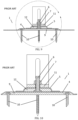
- FIGS. 1 - 14 show examples of prior art attached roof mounts with attachment structures attached to a mount.
- FIGS. 1 - 5 shows a prior art mount ( 1 ) attached to a roof ( 3 ) with an attachment structure ( 11 ) attached to the prior art mount ( 1 ).
- a roof layer may also be on top of the roof ( 3 ).
- the prior art cover ( 4 ) and the prior art additional layers ( 5 ) may be non-rigid materials. After tightening a nut ( 7 ) on a stud ( 6 ), the non-rigid layer of a prior art cover may compress. If there is one or more non-rigid prior additional layers ( 5 ), these may compress also. With these non-rigid layer or layers, an attachment structure ( 11 ) may not be rigidly secured to a prior art mount base ( 9 ) which may reduce a strength and reliability as discussed previously.
- FIGS. 6 - 10 show a prior art mount ( 1 ) with an attachment structure ( 11 ) attached to it.
- a roof ( 3 ) and a prior art top roof layer ( 2 ) is not shown but does apply as it may be in the previous mount ( 1 ).
- FIGS. 6 - 10 these FIGS. may have a prior art cover ( 4 ) and a prior art additional layer ( 5 ) that may be non-rigid. When a nut ( 7 ) may be tightened, the non-rigid additional layer ( 5 ) may compress.
- FIGS. 11 - 14 show another prior art mount ( 1 ).
- a roof and a prior art top roof layer ( 2 ) is not shown but applies as in the first prior art mount ( 1 ).
- FIGS. 11 - 14 there may be a non-rigid layer, prior art cover ( 4 ) between an attachment structure ( 11 ) and a prior art mount base ( 9 ).
- a bolt ( 8 ) may be tightened, a non-rigid prior art cover ( 4 ) may be compressed.
- an attachment structure ( 11 ) may not be rigidly secured to the prior art mount base ( 9 ) which may reduce the strength and reliability as discussed previously.
- the present invention includes a variety of aspects, which may be selected in different combinations based upon the particular application or needs to be addressed.
- the invention may include rigid and even long-term reliable connections between an attachment structure and a bottom of a roof mount and may increase a long-term reliability for water intrusion through mount fastener penetrations into the roof.
- FIG. 1 shows a non-limiting example of a prior art mount.
- FIG. 2 shows a non-limiting example of a prior art mount attached to a roof with an attachment structure.
- FIG. 3 shows a non-limiting example of a prior art mount using non-rigid materials.
- FIG. 4 shows a non-limiting example of a prior art mount.
- FIG. 5 shows a non-limiting example of a prior art mount with an additional layer and an attachment structure.
- FIG. 6 shows a non-limiting example of a prior art cover.
- FIG. 7 shows a non-limiting example of a prior art mount with a cover and attachment structure.
- FIG. 8 shows non-limiting example of a prior art mount.
- FIG. 9 shows a non-limiting example of a prior art of a mount on a roof.
- FIG. 10 shows a non-limiting example of prior art mount.
- FIG. 11 shows a non-limiting example of a prior art cover.
- FIG. 12 shows a non-limiting example of a prior art cover attached to an attachment structure.
- FIG. 13 shows a non-limiting example of a prior art cover.
- FIG. 14 shows a non-limiting example of a prior art mount.
- FIG. 15 shows a non-limiting example of a roof mount attached to a substrate in accordance with some embodiments of the present invention.
- FIG. 16 shows a non-limiting example of a roof mount as shown in FIG. 15 with a section removed in accordance with some embodiments of the present invention.
- FIG. 17 shows a non-limiting example of a mount with an attachment structure attached with a bolt in accordance with some embodiments of the present invention.
- FIG. 18 shows a non-limiting example of a top view of FIG. 17 in accordance with some embodiments of the present invention.
- FIG. 19 shows a non-limiting example of cross-sectional view of FIG. 18 in accordance with some embodiments of the present invention.
- FIG. 20 shows a non-limiting example of an enlarged view of FIG. 19 in accordance with some embodiments of the present invention.
- FIG. 21 shows a non-limiting example of an enlarged view of FIG. 19 in accordance with some embodiments of the present invention.
- FIG. 22 shows a non-limiting example of an enlarged view FIG. 20 in accordance with some embodiments of the present invention.
- FIG. 23 shows a non-limiting example of a mount base with a lock washer in a frame in accordance with some embodiments of the present invention.
- FIG. 24 shows a non-limiting example of a cover in accordance with some embodiments of the present invention.
- FIG. 25 shows a non-limiting example of a mount base in accordance with some embodiments of the present invention.
- FIG. 26 shows a non-limiting example of a mount base in accordance with some embodiments of the present invention.
- FIG. 27 shows a non-limiting example of a resilience constituent in accordance with some embodiments of the present invention.
- FIG. 28 shows a non-limiting example of a resilience constituent in accordance with some embodiments of the present invention.
- FIG. 29 shows a non-limiting example of a compressed resilience constituent in accordance with some embodiments of the present invention.
- FIG. 30 shows a non-limiting example of a non-compressed resilience constituent in accordance with some embodiments of the present invention.
- FIG. 31 shows a non-limiting example of a mount in accordance with some embodiments of the present invention.
- FIG. 32 shows a non-limiting example of a mount attached to attachment structure in accordance with some embodiments of the present invention.
- FIG. 33 shows a top view of FIG. 32 in accordance with some embodiments of the present invention.
- FIG. 35 shows a non-limiting example of an enlarged view of FIG. 33 in accordance with some embodiments of the present invention.
- FIG. 36 shows a non-limiting example of an enlarged view of FIG. 35 in accordance with some embodiments of the present invention.
- FIG. 37 shows a non-limiting example of a mount base in accordance with some embodiments of the present invention.
- FIG. 38 shows a non-limiting example of a mount top in accordance with some embodiments of the present invention.
- FIG. 39 shows a non-limiting example of a mount top in accordance with some embodiments of the present invention.
- FIG. 40 shows a non-limiting example of a resilience constituent in accordance with some embodiments of the present invention.
- FIG. 41 shows a non-limiting example of a compressed resilience constituent in accordance with some embodiments of the present invention.
- FIG. 42 shows a non-limiting example of a resilience constituent in accordance with some embodiments of the present invention.
- FIG. 43 shows a non-limiting example of a non-compressed resilience constituent in accordance with some embodiments of the present invention.
- FIG. 44 shows a non-limiting example of a mount in accordance with some embodiments of the present invention.
- FIG. 45 shows a non-limiting example of a mount attached to an attachment structure in accordance with some embodiments of the present invention.
- FIG. 46 shows a non-limiting example of top view of FIG. 45 in accordance with some embodiments of the present invention.
- FIG. 47 shows a non-limiting example of a cross-section view of FIG. 46 in accordance with some embodiments of the present invention.
- FIG. 48 shows a non-limiting example of an enlarged view as shown in FIG. 47 in accordance with some embodiments of the present invention.
- FIG. 49 shows a non-limiting example of an enlarged view of FIG. 48 in accordance with some embodiments of the present invention.
- FIG. 51 shows a non-limiting example of a mount top in accordance with some embodiments of the present invention.
- FIG. 52 shows a non-limiting example of a mount top in accordance with some embodiments of the present invention.
- FIG. 53 shows a non-limiting example of a resilience constituent in accordance with some embodiments of the present invention.
- FIG. 54 shows a non-limiting example of resilience constituent in accordance with some embodiments of the present invention.
- FIG. 55 shows a non-limiting example of compressed resilience constituent in accordance with some embodiments of the present invention.
- FIG. 56 shows a non-limiting example of a non-compressed resilience constituent in accordance with some embodiments of the present invention.
- FIG. 57 shows a non-limiting example of a mount in accordance with some embodiments of the present invention.
- FIG. 59 shows a non-limiting example of a top view of FIG. 58 in accordance with some embodiments of the present invention.
- FIG. 60 shows a non-limiting example of a cross-section view of FIG. 59 in accordance with some embodiments of the present invention.
- FIG. 61 shows a non-limiting example of an enlarged view of FIG. 60 in accordance with some embodiments of the present invention.
- FIG. 62 shows a non-limiting example of an enlarged view of FIG. 61 in accordance with some embodiments of the present invention.
- FIG. 63 shows a non-limiting example of a mount base in accordance with some embodiments of the present invention.
- FIG. 64 shows a non-limiting example of a mount top in accordance with some embodiments of the present invention.
- FIG. 65 shows a non-limiting example of a mount top in accordance with some embodiments of the present invention.
- FIG. 66 shows non-limiting example of a resilience constituent in accordance with some embodiments of the present invention.
- FIG. 67 shows a non-limiting example of a resilience constituent in accordance with some embodiments of the present invention.
- FIG. 68 shows a non-limiting example of a non-compressed resilience constituent in accordance with some embodiments of the present invention.
- FIG. 69 shows a non-limiting example of a compressed resilience constituent in accordance with some embodiments of the present invention.
- FIG. 70 shows a non-limiting example of a mount in accordance with some embodiments of the present invention.
- FIG. 71 shows a non-limiting example of a mount attached to an attachment structure in accordance with some embodiments of the present invention.
- FIG. 72 shows a non-limiting example of a top view of FIG. 71 in accordance with some embodiments of the present invention.
- FIG. 73 shows a non-limiting example of a cross-section view of FIG. 72 in accordance with some embodiments of the present invention.
- FIG. 74 shows a non-limiting example of an enlarged view of FIG. 73 in accordance with some embodiments of the present invention.
- FIG. 75 shows a non-limiting example of an enlarged view of FIG. 74 in accordance with some embodiments of the present invention.
- FIG. 76 shows a non-limiting example of a mount base with a resilience constituent in accordance with some embodiments of the present invention.
- FIG. 77 shows a non-limiting example of a mount top in accordance with some embodiments of the present invention.
- FIG. 78 shows a non-limiting example of a mount top in accordance with some embodiments of the present invention.
- FIG. 79 shows a non-limiting example of a resilience constituent in accordance with some embodiments of the present invention.
- FIG. 80 shows a non-limiting example of a resilience constituent in accordance with some embodiments of the present invention.
- FIG. 81 shows a non-limiting example of a compressed resilience constituent in accordance with some embodiments of the present invention.
- FIG. 82 shows a non-limiting example of a non-compressed resilience constituent in accordance with some embodiments of the present invention.
- FIG. 83 shows a non-limiting example of a cover in accordance with some embodiments of the present invention.
- FIG. 84 shows a non-limiting example of a mount in accordance with some embodiments of the present invention.
- FIG. 85 shows a non-limiting example of a mount attached to attachment structure in accordance with some embodiments of the present invention.
- FIG. 86 shows a non-limiting example of a top view of FIG. 85 in accordance with some embodiments of the present invention.
- FIG. 87 shows a non-limiting example of a cross-sectional view of FIG. 86 in accordance with some embodiments of the present invention.
- FIG. 88 shows a non-limiting example of an enlarged view of FIG. 87 in accordance with some embodiments of the present invention.
- FIG. 89 shows a non-limiting example of an enlarged view of FIG. 88 in accordance with some embodiments of the present invention.
- FIG. 90 shows a non-limiting example of a mount base in accordance with some embodiments of the present invention.
- FIG. 91 shows a non-limiting example of a mount top in accordance with some embodiments of the present invention.
- FIG. 92 shows a non-limiting example of a mount top in accordance with some embodiments of the present invention.
- FIG. 93 shows a non-limiting example of resilience constituent in accordance with some embodiments of the present invention.
- FIG. 94 shows a non-limiting example of a resilience constituent in accordance with some embodiments of the present invention.
- FIG. 95 shows a non-limiting example of a non-compressed resilience constituent in accordance with some embodiments of the present invention.
- FIG. 96 shows a non-limiting example of a compressed resilience constituent in accordance with some embodiments of the present invention.
- FIG. 97 shows a non-limiting example of mount in accordance with some embodiments of the present invention.
- FIG. 98 shows a non-limiting example of a mount attached to an attachment structure in accordance with some embodiments of the present invention.
- FIG. 99 shows a non-limiting example of a top view of FIG. 98 in accordance with some embodiments of the present invention.
- FIG. 100 shows a non-limiting example of a cross-sectional view of FIG. 99 in accordance with some embodiments of the present invention.
- FIG. 101 shows a non-limiting example of an enlarged view of FIG. 100 in accordance with some embodiments of the present invention.
- FIG. 102 shows a non-limiting example of an enlarged view of FIG. 101 in accordance with some embodiments of the present invention.
- FIG. 103 shows a non-limiting example of an enlarged view of FIG. 101 in accordance with some embodiments of the present invention.
- FIG. 104 shows a non-limiting example of an enlarged view of FIG. 101 in accordance with some embodiments of the present invention.
- FIG. 105 shows a non-limiting example of a mount base in accordance with some embodiments of the present invention.
- FIG. 106 shows a non-limiting example of a top view of a mount top in accordance with some embodiments of the present invention.
- FIG. 107 shows a non-limiting example of a bottom view of a mount top in accordance with some embodiments of the present invention.
- FIG. 108 shows a non-limiting example of a resilience constituent in accordance with some embodiments of the present invention.
- FIG. 109 shows a non-limiting example of a non-compressed resilience constituent in accordance with some embodiments of the present invention.
- FIG. 110 shows a non-limiting example of a compressed resilience constituent in accordance with some embodiments of the present invention.
- FIG. 111 shows a non-limiting example of a bottom view of a mount top in accordance with some embodiments of the present invention.
- FIG. 112 shows a non-limiting example of a resilience constituent in accordance with some embodiments of the present invention.
- FIG. 113 shows a non-limiting example of attachment of a non-compressed resilience constituent in accordance with some embodiments of the present invention.
- FIG. 114 shows a non-limiting example of a compressed resilience constituent in accordance with some embodiments of the present invention.
- FIG. 115 shows a non-limiting example of a bottom perspective view of a bottom mount in accordance with some embodiments of the present invention.
- FIG. 116 shows a non-limiting example of a resilience constituent in accordance with some embodiments of the present invention.
- FIG. 117 shows a non-limiting example of a compressed resilience constituent in accordance with some embodiments of the present invention.
- FIG. 118 shows a non-limiting example of a non-compressed resilience constituent in accordance with some embodiments of the present invention.
- FIG. 119 shows a non-limiting example of a mount top in accordance with some embodiments of the present invention.
- FIG. 120 shows a non-limiting example of a cross-sectional view of FIG. 119 in accordance with some embodiments of the present invention.
- FIG. 121 shows a non-limiting example of a mount top in accordance with some embodiments of the present invention.
- FIG. 122 shows a non-limiting example of a mount in accordance with some embodiments of the present invention.
- FIG. 123 shows a non-limiting example of a mount with an attachment structure in accordance with some embodiments of the present invention.
- FIG. 124 shows non-limiting example of a top view of FIG. 123 in accordance with some embodiments of the present invention.
- FIG. 125 shows a non-limiting example of a cross-section view of FIG. 124 in accordance with some embodiments of the present invention.
- FIG. 126 shows a non-limiting example of an enlarged view of FIG. 125 in accordance with some embodiments of the present invention.
- FIG. 127 shows a non-limiting example of an enlarged view of FIG. 126 in accordance with some embodiments of the present invention.
- FIG. 128 shows a non-limiting example of a mount in accordance with some embodiments of the present invention.
- FIG. 129 shows a non-limiting example of an attachment structure in accordance with some embodiments of the present invention.
- FIG. 130 shows a non-limiting example of an attachment structure in accordance with some embodiments of the present invention.
- FIG. 131 shows a non-limiting example of a resilience constituent in accordance with some embodiments of the present invention.
- FIG. 132 shows a non-limiting example of a compressed resilience constituent in accordance with some embodiments of the present invention.
- FIG. 133 shows a non-limiting example of a non-compressed resilience constituent in accordance with some embodiments of the present invention.
- FIG. 134 shows a non-limiting example of an attachment structure in accordance with some embodiments of the present invention.
- FIG. 135 shows a non-limiting example of threaded rod in an attachment structure in accordance with some embodiments of the present invention.
- FIG. 136 shows a non-limiting example of a threaded rod in an attachment structure in accordance with some embodiments of the present invention.
- FIG. 137 shows a non-limiting example of a threaded rod screwed into a threaded hole in accordance with some embodiments of the present invention.
- FIG. 138 shows a non-limiting example of a resilience constituent with extension holes in accordance with some embodiments of the present invention.
- FIG. 139 shows a non-limiting example of a mount in accordance with some embodiments of the present invention.
- FIG. 140 shows a non-limiting example of a top view of FIG. 139 in accordance with some embodiments of the present invention.
- FIG. 141 shows a non-limiting example of a cross section view of FIG. 140 in accordance with some embodiments of the present invention.
- FIG. 142 shows an enlarged view of FIG. 141 in accordance with some embodiments of the present invention.
- FIG. 143 shows a non-limiting example of a cover in accordance with some embodiments of the present invention.
- FIG. 144 shows a non-limiting example of a top view of a cover in accordance with some embodiments of the present invention.
- FIG. 145 shows a non-limiting example of a cross section view of FIG. 145 in accordance with some embodiments of the present invention.
- FIG. 146 shows a non-limiting example of a cross section view of a mount top over a cover and mount base in accordance with some embodiments of the present invention.
- FIG. 147 shows a non-limiting example of a mount top in accordance with some embodiments of the present invention.
- FIG. 148 shows a non-limiting example of a mount top in accordance with some embodiments of the present invention.
- FIG. 149 shows a non-limiting example of a mount base in accordance with some embodiments of the present invention.
- FIG. 150 shows a non-limiting example of a cover in accordance with some embodiments of the present invention.
- FIG. 151 shows a non-limiting example of a mount bottom with a locking feature in accordance with some embodiments of the present invention.
- FIG. 152 shows a non-limiting example of mount top with a locking feature in accordance with some embodiments of the present invention.
- FIG. 153 shows a non-limiting example of mount attached to a component in accordance with some embodiments of the present invention.
- Embodiments of the present invention may provide methods for attachment of materials comprising the steps of providing a roof mount; covering part of said roof mount with a cover; and perhaps even compressing a resilience constituent against said cover and said roof mount.
- Other embodiments may provide providing a roof mount having a top roof mount and a bottom roof mount; placing a cover over part of said bottom roof mount; attaching said top roof mount to said bottom roof mount; and perhaps even compressing an elastic substance against said cover during said step of attaching said top roof mount to said bottom roof mount.
- embodiments of the present invention may provide a rigid emplacement configuration comprising a roof mount having a top roof mount and a bottom roof mount; a cover configured to cover part of said bottom roof mount; and perhaps even a resilience constituent configured to compress when said top roof mount is attached to said bottom roof mount.
- embodiments of the present invention may provide a rigid emplacement configuration comprising a roof mount; a cover configured to cover part of roof mount; and perhaps even a resilience constituent configured to compress against said cover and said roof mount.
- a mount may be an emplacement configuration which may attach a component to a material such as but not limited to a flat surface, a surface, a roof, a deck, or the like.
- a roof mount ( 13 ) may be placed and even attached to a roof ( 3 ).
- a cover ( 16 ) may be placed on part of a roof mount and a resilience constituent ( 23 ) may be compressed against a cover and a roof mount.
- a mount, such as a roof mount may be any design that can be attached to a surface.
- a rigid connection between an attachment structure and a mount base may allow for reduced additional attachment structures. It also may allow for less mounts.
- a rigid connection may not have non-rigid materials between an attachment structure and a mount base.
- the present invention may allow more independence between a cover water intrusion and even an attachment of an attachment structure.
- a resilience constituent may be made of a material including, but not limited to, metal, stainless steel, hard plastic, hard reinforced plastic, hard polymer, hard reinforced polymer, any combination thereof, or the like.
- a resilience constituent may not be an elastomer such as rubber or the like.
- a resilience constituent may have a flexural modulus greater than about 0.5 GPa (gigapascals) for polymers and perhaps even a modulus of elasticity greater than about 20 GPa (gigapascals) for metals. Of course, any amount may be used.
- a resilience constituent may be coated with a coating such as but not limited to an elastomer or the like.
- low-profile mounts may have one or more non-rigid covers or other non-rigid materials between an attachment structure and a mount base which may reduce mount reliability and rigidity.
- Embodiments of the present invention may provide that a mount base can be attached to a substrate which may be, but is not limited to a roof, wall, slab, or any other attachment structure that needs a mount.
- a substrate may be, but is not limited to, a roof membrane, built up roof, a liquid applied coating, acrylic, or any other roof water proofing material.
- a water proofing layer may include all methods of water proofing a substrate. If the substrate may already be water proof or if water proofing may not be required, a mount base can be directly attached to a substrate. Waterproof may include water resistant.
- an adhesive may be, but is not limited to, an epoxy, adhesive tape, sealant, butyl, petroleum or coal product, polymer or any other type of adhesive.
- Adhesive may refer to heat welding a cover perhaps to a water proof layer.
- An adhesive may be any method of attaching a cover to a substrate or even a water proofing layer.
- a cover may be, but is not limited to a membrane, a liquid applied coating, asphalt, modified asphalt, or any other water proof material, or the like.
- a cover may be a ring, flexible ring, or the like.
- a membrane may be, but is not limited to TPO, PVC, EPDM, or any other type of roof membrane, or the like.
- a membrane may be reinforced or may even be non-reinforced.
- a liquid applied coating may be but is not limited to silicone, acrylic, urethane, or any other liquid coating, or the like.
- Asphalt may be but is not limited to BUR, Bitumen, Modified Bitumen, Tar, felt, or any other asphalt type material, or the like. Reinforced fabric or even fiber may be used on liquid applied coatings. For asphalt type roofs and even applied coatings, fabric or even fiber reinforcement may be used.
- a sealant may be added perhaps to help liquid penetration.
- a sealant may be, but is not limited to silicone, urethane, latex, acrylic, polymer, butyl, solid or foam elastomer or any other type of sealant, or the like.
- the term sealant or seal may cover all sealants.
- An elastomer may be, but is not limited to a washer, O-ring, or any other shape, or the like.
- An elastomer may have PSA or even an adhesive layer perhaps on at least one surface.
- Fasteners may include, but is not limited to bolts, studs, threaded rods, nuts, or the like. Any fastener or combination of fasteners may be used in the various embodiments of the present invention.
- a threaded hole could be a threaded stud or any other type of attachment, or the like.
- An attachment structure may be a bracket, L-bracket, stanchion, an attachment part of a component, any structure which may be attached to a mount, any combination thereof, or the like.
- FIGS. 15 - 100 show non-limiting examples of various types of rigid cover mounts perhaps some with deformed cover mounts.
- FIGS. 15 - 30 and FIG. 138 shows a non-limiting example of a mount ( 13 ) attached to a substrate ( 14 ) and an attachment structure ( 11 ) attached to a mount ( 13 ).
- FIGS. 15 and 16 show a non-limiting example of a mount ( 13 ) attached to a substrate ( 14 ) perhaps with screws ( 10 ) through a mount base ( 18 ).
- a mount ( 13 ) may have a top roof mount ( 19 ) which may be a mount top and a bottom roof mount ( 18 ) which may be a mount base.
- FIG. 16 is the same as FIG. 15 perhaps except there is a section removed from the mount top ( 19 ) and a cover ( 16 ) so the components underneath may be viewed.
- FIG. 15 may have a top roof mount ( 19 ) which may be a mount top and a bottom roof mount ( 18 ) which may be a mount base.
- FIG. 16 is the same as FIG. 15 perhaps except there is a section removed from the mount
- an attachment structure ( 11 ) may be attached with a bolt ( 8 ) to a mount top ( 19 ).
- the present invention may provide a top roof mount, a bottom roof mount, and even an elastic substance.
- An elastic substance may be an elastomer, such as rubber or the like, and may be compressed against a cover perhaps during attachment of a top roof mount to a bottom roof mount which may secure the mount.
- FIG. 18 shows a top view of FIG. 17 and FIG. 19 is a cross-sectional view of FIG. 18 .
- FIGS. 20 and 21 show enlarged views of those shown in FIG. 19 .
- FIG. 22 shows an enlarged view of FIG. 20 .
- Embodiments of the present invention may provide placing a cover over part ( 22 ) of a bottom roof mount perhaps as understood in FIGS. 18 , 19 , attaching a top roof mount ( 19 ) to a bottom roof mount ( 18 ); and perhaps even compressing a resilience constituent against a cover during the step of attaching a top roof mount to a bottom roof mount.
- a resilience constituent may contact on a top or even a bottom of a cover.
- a compressed and non-compressed resilience constituent may be understood in the non-limiting example in FIGS. 29 and 30 .
- a bottom roof mount may be secured to a roof or other substrate perhaps with screws ( 10 ) and screw holes ( 33 ) or the like as discussed herein.
- FIG. 23 show a non-limiting example of an assembly of a mount base ( 18 ) perhaps with a lock washer ( 24 ).
- a mount base may have screws ( 10 ) and even mount base screw holes ( 43 ). Screws ( 10 ) may attach a mount base ( 18 ) on a substrate ( 14 ) perhaps as shown in FIGS. 16 , 19 , and 20 .
- FIG. 24 shows a non-limiting example of a cover ( 16 ) perhaps prior to attaching it to a mount base ( 18 ).
- FIGS. 25 - 26 show a non-limiting example of a mount top ( 19 ) and
- FIGS. 27 - 30 show a non-limiting example of a resilience constituent ( 23 ).
- FIGS. 42 and 43 may be a cross section view shown in FIG. 41 .
- FIG. 29 shows a non-limiting example of a compressed resilience constituent ( 23 ) and
- FIG. 30 shows a non-limiting example of a non-compressed resilience constituent ( 23 ).
- a mount base extension ( 25 ) may be added under a mount base ( 18 ) perhaps to increase a load bearing surface on a substrate ( 14 ).
- a non-limiting example of mount base extension ( 25 ) is shown in FIGS. 19 - 22 and FIG. 138 .
- Non-limiting examples of mount base extension holes ( 48 ) are shown in FIG. 138 and may align with mount base screw holes ( 33 ) perhaps as shown in FIG. 23 .
- a cover ( 16 ) perhaps with a cover hole ( 47 ) as shown in FIG. 24 may be placed on top of a mount base ( 18 ) as shown in FIG. 23 .
- a mount top ( 19 ) perhaps as shown in FIGS. 25 and 26 may be started into a mount base ( 18 ) perhaps by engaging mount top threads ( 30 ) in mount base threads ( 31 ).
- a mount top base ( 19 ) may be screwed into a mount base ( 18 )
- a mount top cover surface ( 34 ) may push a cover ( 16 ) into a resilience constituent ( 23 ) perhaps against a mount base spring surface ( 39 ) and may even compress a resilience constituent ( 23 ).
- Embodiments of the present invention may provide compressing a resilience constituent perhaps until a top roof mount may rigidly contact or even attach to a bottom roof mount.
- a mount top ( 19 ) may be securely tightened perhaps when using mount top spanner holes ( 21 ) or any other feature which may allow a firm grip on a mount top ( 19 ).
- a mount top stop surface ( 26 ) may rigidly contact a top flat area of a lock washer ( 24 ).
- a bottom flat area of a lock washer ( 24 ) may rigidly contact a mount base stop surface ( 27 ) which may make a rigid connection between a mount top ( 19 ) and a mount base ( 18 ).
- Teeth of a lock washer ( 24 ) may be embedded into a mount top stop surface ( 26 ) and a mount base stop surface ( 27 ) may prevent a mount top ( 19 ) from unscrewing from a mount base ( 18 ).
- a top roof mount may be a rigid top roof mount and a bottom roof mount may be a rigid bottom roof mount.
- a mount top stop surface ( 26 ) may contact a mount base stop surface ( 27 ) and may have a rigid connection between these surfaces. This may make a rigid connection between a mount top ( 19 ) and a mount base ( 18 ). Locking features on a mount top stop surface ( 26 ) or perhaps even on a mount base stop surface ( 27 ), or both surfaces, may prevent a mount top ( 19 ) from unscrewing from a mount base ( 18 ).
- a resilience constituent ( 23 ) When a resilience constituent ( 23 ) may be compressed, it may exert a force on a bottom of a cover ( 16 ) and may push a top cover against a mount top cover surface ( 34 ) which may create a water intrusion barrier between a top of a cover ( 16 ) and even a mount top cover surface ( 34 ).
- a cover ( 16 ) may be attached with an adhesive ( 17 ) perhaps to a water proof layer ( 15 ) such as shown in FIG. 21 . This may create a water intrusion barrier perhaps between a cover ( 16 ) and a water proof layer ( 15 ). With water intrusion barriers discussed, water intrusion into a substrate ( 14 ) perhaps due to a mount ( 13 ) may not occur. When a bolt ( 8 ) may be tightened, an attachment structure bottom surface ( 28 ) may make a rigid contact with a mount top surface ( 29 ). There may now be rigid contacts between an attachment structure ( 11 ) and a mount base ( 18 ).
- FIGS. 31 - 43 , 24 and 138 shows a non-limiting example of a mount ( 13 ) and an attachment structure ( 11 ) attached to a mount ( 13 ).
- FIGS. 15 - 30 and 138 show non-limiting examples of a substrate ( 14 ), adhesive ( 17 ), a water proof layer ( 15 ), and even a mount extension ( 25 ).
- FIG. 31 shows a non-limiting example of a mount ( 13 ).
- FIG. 32 may be the same as FIG. 31 except an attachment structure ( 11 ) may be attached to a mount ( 13 ).
- FIG. 33 is a top view of FIG. 32 and
- FIG. 34 is a cross-section view of FIG. 33 .
- FIG. 35 is an enlarged view of what is shown in FIG. 34 .
- FIG. 36 is an enlarged view of what is shown in FIG. 35 .
- FIG. 37 shows a non-limiting example of a mount base ( 18 ) perhaps with screws ( 10 ).
- FIG. 24 shows a non-limiting example of a cover ( 16 ) perhaps with a cover hole ( 47 ) such as before it may be attached to a mount base ( 18 ).
- FIGS. 38 and 39 show a non-limiting example of a mount top ( 19 ).
- FIGS. 40 - 43 show a non-limiting example of a resilience constituent ( 23 ).
- FIG. 41 show a non-limiting example of a compressed resilience constituent ( 23 ) and
- FIG. 43 show a non-limiting example of a non-compressed resilience constituent ( 23 ).
- a cover ( 16 ) may have a cover hole ( 47 ) and may be placed on a mount base ( 18 ) perhaps as shown in FIG. 37 .
- a mount top ( 19 ) may be screwed onto a stud ( 6 ) perhaps in a mount top threaded hole ( 20 ).
- a hex shape of a mount top ( 19 ) may be used to tighten a mount top ( 19 ) which may continue to compress a resilience constituent ( 23 ) perhaps until a mount top stop surface ( 26 ) may contact a mount base stop surface ( 27 ) which may create a rigid connection between a mount top ( 19 ) and a mount base ( 18 ).
- a resilience constituent compression force may force a resilience constituent ( 23 ) against a spring seal ( 36 ) and perhaps even a top of a cover ( 16 ).
- a resilience constituent ( 23 ) may force a spring seal ( 36 ) against a mount top spring seal surface ( 49 ) and may even force a bottom of a cover perhaps against a mount base cover surface ( 40 ).
- This may create a water intrusion barrier perhaps between a mount top spring seal surface ( 49 ) and a spring seal ( 36 ); between a spring seal ( 36 ) and a resilience constituent ( 23 ); between a resilience constituent ( 23 ) and a cover ( 16 ); and perhaps even between a cover ( 16 ) and a mount base cover surface ( 40 ).
- This may create a water intrusion barrier perhaps between a mount top spring seal surface ( 49 ) and even a mount base cover surface, ( 40 ).
- a mount base lip ( 37 ) may allow a cover ( 16 ) to be closer to a bottom of a mount base ( 18 ). This may allow a cover ( 16 ) perhaps to conform better when it may be attached to a water proof layer ( 15 ).
- a seal ( 35 ) may create a water intrusion barrier perhaps between a top mount ( 19 ) and even a base mount ( 18 ) such as around a stud ( 6 ).
- a head of a stud ( 6 ) perhaps when pressed into a mount base ( 18 ) may create a water intrusion barrier between a stud ( 6 ) and a mount base ( 18 ).
- a spring seal ( 36 ) may be a non-rigid material such as but not limited to an elastomer or the like.
- a spring seal ( 36 ) could be attached to a resilience constituent ( 23 ).
- a cover ( 16 ) may be attached with an adhesive ( 17 ) to a water proof layer ( 15 ) as may be understood in FIG. 21 . This may create a water intrusion barrier between a cover ( 16 ) and a water proof layer ( 15 ). With water intrusion barriers discussed, there may be little to no water intrusion path to a substrate ( 14 ) perhaps due to a mount ( 13 ).
- An attachment structure ( 11 ) may be attached to a mount top ( 19 ).
- an attachment structure bottom surface ( 28 ) may contact a mount top surface ( 29 ) which may create a rigid connection between an attachment structure ( 11 ) and a mount top ( 19 ). This may create a rigid connection between an attachment structure ( 11 ) and a mount base ( 18 ).
- FIGS. 44 - 56 , 24 and 138 show a non-limiting example of a mount ( 13 ) and an attachment structure ( 11 ) attached to a mount ( 13 ).
- a substrate ( 14 ), adhesive ( 17 ), water proof layer ( 15 ), and perhaps even a mount extension ( 25 ) may not be shown but may be used.
- FIGS. 15 - 30 and 138 may provide non-limiting examples of a substrate ( 14 ), adhesive ( 17 ), water proof layer ( 15 ), and even a mount extension ( 25 ).
- FIG. 44 shows a non-limiting example of a mount ( 13 ).
- FIG. 45 may be the same as FIG. 44 perhaps except an attachment structure ( 11 ) may be attached to a mount ( 13 ).
- FIG. 46 is a top view of FIG. 45 and
- FIG. 47 is a cross-section view of FIG. 46 .
- FIG. 48 is an enlarged view as shown in FIG. 47 .
- FIG. 49 is an enlarged view as shown in FIG. 48 .
- Embodiments of the present invention may provide that cover may be placed close ( 54 ) to a roof or the like.
- a cover may be placed over or even around part of a roof mount, such as a bottom roof mount; however, if a cover may be rigid, it may not flex.
- a cover may be between about 0.5 to about 0.25 inches above a roof or the like. Of course, any placement may be used and all measurements are included in this disclosure.
- FIG. 50 shows a non-limiting example of a mount base ( 18 ) perhaps with screws ( 10 ).
- FIG. 24 shows a non-limiting example of a cover ( 16 ) perhaps with a cover hole ( 47 ) before it may be attached to a mount base ( 18 ).
- FIGS. 51 and 52 show a non-limiting example of a mount top ( 19 ).
- FIGS. 53 - 56 show a non-limiting example of a resilience constituent ( 23 ).
- FIG. 55 shows a non-limiting example of a compressed resilience constituent ( 23 ) and
- FIG. 56 shows a non-limiting example of a non-compressed resilience constituent ( 23 ).
- a cover ( 16 ) perhaps with a cover hole ( 47 ) may be placed on a mount base ( 18 ) perhaps as shown in FIG. 50 .
- a mount top ( 19 ) may be screwed onto a stud ( 6 ) perhaps in a mount top bottom threaded hole ( 46 ).
- Mount top spanner holes ( 21 ) may be used to tighten a mount top ( 19 ) which may continue to compress a resilience constituent ( 23 ) until a mount top stop surface ( 26 ) may contact a mount base stop surface ( 27 ) which may create a rigid connection between a mount top ( 19 ) and a mount base ( 18 ).
- a resilience constituent ( 23 ) may be compressed between a bottom of a cover ( 16 ) and a mount base spring surface ( 39 ).
- a resilience constituent compression force may force a resilience constituent ( 23 ) against a cover ( 16 ) and may even force a cover ( 16 ) against a mount top cover surface ( 34 ) which may create a water intrusion barrier perhaps between a top of a cover ( 16 ) and a mount top cover surface ( 34 ).
- Localized pressure from an edge of a resilience constituent ( 23 ) may create further pressure between a top of a cover ( 16 ) and against a mount top cover surface ( 34 ) which may create a water intrusion barrier.
- a cover ( 16 ) may be attached with an adhesive ( 17 ) perhaps to a water proof layer ( 15 ) perhaps as shown in FIG. 21 . This may create a water intrusion barrier perhaps between a cover ( 16 ) and a water proof layer ( 15 ). With water intrusion barriers discussed, there may be little to no water intrusion path to a substrate ( 14 ) perhaps due to a mount ( 13 ).
- An attachment structure ( 11 ) may be attached to a mount top ( 19 ).
- an attachment structure bottom surface ( 28 ) may contact a mount top surface ( 29 ) which may create a rigid connection between an attachment structure ( 11 ) and a mount top ( 19 ). This may create a rigid connection between an attachment structure ( 11 ) and a mount base ( 18 ).
- a mount top ( 19 ) may be attached to a mount base ( 18 ) perhaps with multiple screws from a bottom of a mount base ( 18 ) into a mount top ( 19 ). This may be an alternative to using a stud ( 6 ). Multiple screws may offset to a mount top threaded hole ( 20 ) which may allow a mount top ( 19 ) to be a smaller height.
- FIGS. 57 - 69 , 24 and 138 show a non-limiting example of a mount ( 13 ) and even an attachment structure ( 11 ) attached to a mount ( 13 ).
- a substrate ( 14 ), adhesive ( 17 ), a water proof layer ( 15 ), and perhaps even a mount extension ( 25 ) may not be shown but may apply.
- FIGS. 15 - 30 , and 138 may provide a non-limiting example of a substrate ( 14 ), adhesive ( 17 ), water proof layer ( 15 ), and even a mount extension ( 25 ).
- FIG. 57 shows a non-limiting example of a mount ( 13 ).
- FIG. 58 may be the same as FIG. 57 perhaps except an attachment structure ( 11 ) may be attached to a mount ( 13 ).
- FIG. 59 is a top view of FIG. 58 and
- FIG. 60 is a cross-section view of FIG. 59 .
- FIG. 61 is an enlarged view of that as shown in FIG. 60 .
- FIG. 62 is an enlarged view of that as shown in FIG. 61 .
- FIG. 63 shows a non-limiting example of a mount base ( 18 ) perhaps with screws ( 10 ) and even a resilience constituent ( 23 ).
- FIG. 24 shows a non-limiting example of a cover ( 16 ) perhaps with a cover hole ( 47 ) before it may be attached to a mount base ( 18 ).
- FIGS. 64 and 65 show a non-limiting example of a mount top ( 19 ).
- FIGS. 66 - 69 show a non-limiting example of a resilience constituent ( 23 ).
- FIG. 69 shows a non-limiting example of a compressed or even bent resilience constituent ( 23 ) and
- FIG. 68 shows a non-limiting example of a non-compressed resilience constituent ( 23 ).
- a cover ( 16 ) perhaps with a cover hole ( 47 ) may be placed on a mount base ( 18 ) perhaps as shown in FIG. 63 .
- a mount top ( 19 ) may be started into a mount base ( 18 ) perhaps by engaging mount top threads ( 30 ) in mount base threads ( 31 ).
- Mount top spanner holes ( 21 ) may be used to tighten a mount top ( 19 ) which may continue to compress a resilience constituent ( 23 ) perhaps until a mount top stop surface ( 26 ) may contact a top of a resilience constituent ( 23 ).
- a bottom of a resilience constituent ( 23 ) may contact a mount base stop surface ( 27 ) which may create a rigid connection between a mount top ( 19 ) and a resilience constituent ( 23 ) and a resilience constituent ( 23 ) and a mount base ( 18 ). This may create a rigid connection between a mount top ( 19 ) and a mount base ( 18 ).
- a resilience constituent ( 23 ) may have locking teeth ( 38 ) that may embed into a mount top stop surface ( 26 ) and even a base stop surface ( 27 ) which may keep a mount top ( 19 ) and a mount base ( 18 ) from loosening.
- a resilience constituent ( 23 ) may be compressed or even bent which may allow a resilience constituent to push up on a bottom of a cover ( 16 ), push a top of a cover ( 16 ) against a mount top cover surface ( 34 ) which may create a water intrusion barrier between a top of a cover ( 16 ) and even a mount top cover surface ( 34 ).
- Localized pressure from an edge of a resilience constituent ( 23 ) may create further pressure between a top of a cover ( 16 ) and a mount top cover surface ( 34 ) which may create a water intrusion barrier.
- a cover ( 16 ) may be attached with an adhesive ( 17 ) perhaps to a water proof layer ( 15 ) perhaps as shown in FIG. 21 . This may create a water intrusion barrier between a cover ( 16 ) and a water proof layer ( 15 ). With water intrusion barriers discussed, there may be no water intrusion path to a substrate ( 14 ) perhaps due to a mount ( 13 ).
- An attachment structure ( 11 ) may be attached to a mount top ( 19 ).
- an attachment structure bottom surface ( 28 ) may contact a mount top surface ( 29 ) which may create a rigid connection between an attachment structure ( 11 ) and a mount top ( 19 ). This may create a rigid connection between an attachment structure ( 11 ) and a mount base ( 18 ).
- FIGS. 70 - 83 , 24 , and 138 shows a non-limiting example of a mount ( 13 ), and an attachment structure ( 11 ) which may be attached to a mount ( 13 ).
- a substrate ( 14 ), adhesive ( 17 ), water proof layer ( 15 ), and even a mount extension ( 25 ) may not be shown may be apply.
- FIG. 70 shows a non-liming example of a mount ( 13 ).
- FIG. 71 may be the same as FIG. 70 perhaps except an attachment structure ( 11 ) may be attached to a mount ( 13 ).
- FIG. 72 shows a top view of FIG. 71 and
- FIG. 73 is a cross-sectional view of FIG. 72 .
- FIG. 74 shows an enlarged of the views shown in FIG. 73 .
- FIG. 75 shows an enlarged view of FIG. 74 .
- FIG. 76 shows an assembly of a mount base ( 18 ) which may have a resilience constituent ( 23 ), screws ( 10 ), and even mount base screw holes ( 43 ). Screws ( 10 ) may attach a mount base ( 18 ) perhaps on a substrate ( 14 ) perhaps as shown in FIGS. 16 , 19 , and 20 .
- FIG. 76 shows a non-liming example of a mount base ( 18 ) perhaps with screws ( 10 ) and even a resilience constituent ( 23 ).
- FIG. 24 shows a non-liming example of a cover ( 16 ) which may have a cover hole ( 47 ) such as before it may be attached to a mount base ( 18 ).
- FIGS. 77 and 78 show a non-liming example of a mount top ( 19 ).
- FIGS. 79 - 82 show non-liming example of a resilience constituent ( 23 ).
- FIG. 81 shows a non-liming example of a compressed resilience constituent ( 23 ) and
- FIG. 82 shows a non-liming example of a non-compressed resilience constituent ( 23 ).
- FIG. 83 shows a non-liming example of a cover ( 16 ) which may be lifted up perhaps to expose screws ( 10 ).
- This FIG. 83 shows a non-liming example that a mount ( 13 ) may be assembled prior to attaching a mount base ( 18 ) with screws ( 10 ) to a substrate ( 14 ) perhaps by lifting up a cover ( 16 ).
- a cover ( 16 ) with cover hole ( 47 ), as shown in FIG. 24 may be placed on a top of a mount base ( 18 ).
- a mount top ( 19 ) may then be started into a mount base ( 18 ) perhaps by engaging mount top threads ( 30 ) in mount base threads ( 31 ).
- a resilience constituent ( 23 ) may push a cover ( 16 ) against a mount top cover surface ( 34 ).
- a resilience constituent ( 23 ) may compress perhaps until a mount top stop surface ( 26 ) may rigidly contact a mount base stop surface ( 27 ).
- a mount base spring surface ( 39 ) may vertically retain a resilience constituent from moving downward.
- a mount top ( 19 ) may be securely tightened perhaps using mount top spanner holes ( 21 ) or any other feature which may allow a firm grip on a mount top ( 19 ).
- a mount top stop surface ( 26 ) may rigidly contact a mount base stop surface ( 27 ) which may make a rigid connection between a mount top ( 19 ) and a mount base ( 18 ).
- a resilience constituent ( 23 ) When a resilience constituent ( 23 ) may be compressed, it may exert a force on a bottom of a cover ( 16 ) and may even push a top cover against a mount top cover surface ( 34 ) which may create a water intrusion barrier between a top of a cover ( 16 ) and a mount top cover surface ( 34 ). Localized pressure from an edge of a resilience constituent ( 23 ) may create further pressure between a top of a cover ( 16 ) and against a mount top cover surface ( 34 ) which may increase a water intrusion barrier.
- a cover ( 16 ) may be attached with an adhesive ( 17 ) to a water proof layer ( 15 ) perhaps as shown in FIG. 21 . This may create a water intrusion barrier between a cover ( 16 ) and a water proof layer ( 15 ). With water intrusion barriers discussed, water intrusion into a substrate ( 14 ) perhaps due to a mount ( 13 ) may not occur. When a bolt ( 8 ) may be tightened, an attachment structure bottom surface ( 28 ) may make a rigid contact with a mount top surface ( 29 ).
- a mount base ( 18 ) may be attached to a substrate ( 14 ) perhaps with screws ( 10 ) through mount base screw holes ( 33 ) perhaps after attaching a mount top ( 19 ).
- a mount ( 13 ) may be assembled and then attached to a substrate ( 14 ).
- a cover ( 16 ) may be lifted and screws ( 10 ) may be screwed through mount base screw holes, into a substrate ( 14 ).
- An attachment structure ( 11 ) may be attached to a mount ( 13 ) perhaps prior to a mount ( 13 ) being attached to a substrate ( 14 ).
- Additional attachment structures may be attached to an attachment structure ( 11 ) perhaps prior to a mount ( 13 ) attachment to a substrate ( 14 ). This may allow for moving attachment structures around perhaps prior to a mount ( 13 ) attachment. Once everything may be in place, screws ( 10 ) may be screwed in a substrate ( 14 ) and a cover ( 16 ) which may then be attached to a water proof layer ( 15 ) with an adhesive ( 17 ) perhaps as shown in FIG. 21 .
- FIGS. 84 - 96 , 24 and 138 show a non-limiting example of a mount ( 13 ) and an attachment structure ( 11 ) may be attached to a mount ( 13 ).
- a substrate ( 14 ), an adhesive ( 17 ), a water proof layer ( 15 ), and perhaps a mount extension ( 25 ) may not be shown but may apply in some embodiments.
- FIG. 90 shows a non-limiting example of a mount base ( 18 ) perhaps with screws ( 10 ) and even a resilience constituent ( 23 ).
- FIG. 24 shows a non-limiting example of a cover ( 16 ) with a cover hole ( 47 ) perhaps before it may be attached to a mount base ( 18 ).
- FIGS. 91 and 92 show a non-limiting example of a mount top ( 19 ).
- FIGS. 93 - 96 show a non-limiting example of a resilience constituent ( 23 ).
- FIG. 96 shows a non-limiting example of a compressed resilience constituent ( 23 ) and
- FIG. 95 shows a non-limiting example of a non-compressed resilience constituent ( 23 ).
- a resilience constituent may be a disk ( 57 ) perhaps with a middle ridge ( 52 ) such as shown in the non-limiting example in FIGS. 89 and 93 .
- a ridge may be near a middle of a disk or may be at any location on a disk or the like. In some embodiments, there may be more than one ridge in a resilience constituent.
- a middle ridge may apply pressure to a roof mount perhaps when compressed.
- a middle ridge may be an upper edge, an angle, a wave or the like and may have a height of a ridge of between about 0.01 and about 0.1 inches. Of course, any height may be used and all are included in this disclosure.
- a mount base spring surface ( 39 ) may prevent a resilience constituent ( 23 ) from vertically moving downward.
- a mount top ( 19 ) may be securely tightened perhaps using mount top spanner holes ( 21 ) or any other feature that could allow a firm grip on a mount top ( 19 ).
- a mount top stop surface ( 26 ) may rigidly contact a mount base stop surface ( 27 ) which may make a rigid connection between a mount top ( 19 ) and a mount base ( 18 ).
- a resilience constituent ( 23 ) When a resilience constituent ( 23 ) may be compressed, it may exert a force on a bottom of a cover ( 16 ) and even push a top cover against a mount top cover surface ( 34 ) which may create a water intrusion barrier between a top of a cover ( 16 ) and a mount top cover surface ( 34 ). Localized pressure from a protrusion of a resilience constituent ( 23 ) may create further pressure between a top of a cover ( 16 ) and a mount top cover surface ( 34 ) which may cause a water intrusion barrier.
- a cover ( 16 ) may be attached with an adhesive ( 17 ) perhaps to a water proof layer ( 15 ) perhaps as shown in FIG. 21 . This may create a water intrusion barrier between a cover ( 16 ) and a water proof layer ( 15 ). With water intrusion barriers discussed, water intrusion into a substrate ( 14 ) perhaps due to a mount ( 13 ) may not occur.
- an attachment structure bottom surface ( 28 ) may make a rigid contact with a mount top upper surface ( 41 ). There may now be rigid contacts between an attachment structure ( 11 ) and a mount base ( 18 ).
- FIGS. 97 - 120 , and 24 show a non-limiting example of a mount ( 13 ) and an attachment structure ( 11 ) perhaps attached to a mount ( 13 ).
- a substrate ( 14 ), an adhesive ( 17 ), a water proof layer ( 15 ), and a mount extension ( 25 ) may not be shown but may apply in some embodiments.
- FIG. 105 shows a non-limiting example of a mount base ( 18 ) perhaps with screws ( 10 ) and even a resilience constituent ( 23 ).
- a resilience constituent ( 23 ) shown may be shown in FIGS. 100 - 102 .
- FIG. 24 shows a non-limiting example of a cover ( 16 ) perhaps with a cover hole ( 47 ) before it may be attached to a mount base ( 18 ).
- FIG. 106 shows a non-limiting example of a top perspective view of a mount top ( 19 ).
- FIG. 107 shows a non-limiting example of a bottom perspective view of a mount top ( 19 ) perhaps as shown in FIGS. 100 - 102 .
- FIG. 111 shows a non-limiting example of a bottom perspective view of a mount top ( 19 ) in FIG. 103 .
- FIG. 115 shows a non-limiting example of a bottom perspective view of a mount top ( 19 ) in FIG. 104 .
- FIGS. 108 - 110 show a non-limiting example of a resilience constituent ( 23 ) perhaps was shown in FIGS. 100 - 102 .
- a resilience constituent ( 23 ) may be an arched disk ( 53 ) perhaps as may be understood from the non-limiting examples as shown in FIGS. 104 , 112 and 113 .
- An arched disk may have an arch height of about 0.25 inches, between about 0.1 and about 0.5 inches, or the like. Of course, any height can by used and all are included in this disclosure.
- An arched disk or any other resilience constituent may be snapped into a top mount perhaps when a resilience constituent may be compressed and a cover may be deformed when the arched disk may be snapped into place.
- FIG. 110 shows a non-limiting example of a compressed resilience constituent ( 23 ) and FIG. 109 shows a non-limiting example of a non-compressed resilience constituent ( 23 ).
- FIGS. 112 - 114 show a non-limiting example of a resilience constituent ( 23 ) in FIGS. 103 , 119 and 120 .
- FIG. 114 shows a non-limiting example of a compressed resilience constituent ( 23 ) and FIG. 113 shows a non-limiting example of a non-compressed resilience constituent ( 23 ).
- FIGS. 116 - 118 show a resilience constituent ( 23 ) in FIG. 104 .
- FIG. 117 shows a non-limiting example of a compressed resilience constituent ( 23 ) and FIG. 118 shows a non-limiting example of a non-compressed resilience constituent ( 23 ).
- FIG. 119 shows a non-limiting example of a mount top ( 19 ), a cover ( 16 ), and a resilience constituent ( 23 ) assembly.
- FIG. 120 shows a cross-section of FIG. 119 .
- FIG. 121 shows a non-liming example of a mount top with a threaded hole ( 20 ) and spanner holes ( 21 ).
- a cover ( 16 ) perhaps with cover hole ( 47 ) as shown in FIG. 24 may be placed on a top of a mount base ( 18 ).
- a mount top ( 19 ) may then be screwed into a mount base ( 18 ) perhaps by engaging mount top threads ( 30 ) in mount base threads ( 31 ).
- a mount base spring surface ( 39 ) may hold a resilience constituent ( 23 ) in place and a resilience constituent ( 23 ) may push a cover ( 16 ) into a mount top ( 19 ) and even against a mount top cover surface ( 34 ).
- a resilience constituent ( 23 ) may compress perhaps until a mount top stop surface ( 26 ) may rigidly contact a mount base stop surface ( 27 ).
- a mount top ( 19 ) may be securely tightened perhaps using mount top spanner holes ( 21 ) or any other feature which may allow a firm grip on a mount top ( 19 ).
- a mount top stop surface ( 26 ) may rigidly contact a mount base stop surface ( 27 ) which may make a rigid connection between a mount top ( 19 ) and a mount base ( 18 ).
- a top roof mount may include at least one mount top protrusion ( 41 ).
- a mount top protrusion ( 41 ) may deform a cover ( 16 ) and may increase a water intrusion barrier effectiveness. This may also increase a pull out strength of a cover ( 16 ) from a mount top ( 19 ).
- FIG. 103 shows a non-limiting example of a resilience constituent ( 23 ) and a mount top ( 19 ) that may be similar to the ones in FIG. 102 but a resilience constituent ( 23 ) may be able to be retained in place by a spring pocket ( 32 ) perhaps in a mount top ( 19 ). This may allow a resilience constituent ( 23 ) to be pushed up into a mount top ( 19 ) and may hold a cover ( 16 ) in place perhaps prior to attaching a mount top ( 19 ) to a mount base ( 18 ).
- FIGS. 119 - 121 show a non-limiting example of a mount top ( 19 ), cover ( 16 ), and a resilience constituent ( 23 ), assembly.
- FIG. 104 shows a non-limiting example of a resilience constituent ( 23 ) and a mount top ( 19 ) that may have a spring pocket ( 32 ) and may retain a resilience constituent ( 23 ).
- this may allow for a mount top ( 19 ), a cover ( 16 ), and even a resilience constituent ( 23 ), to be assembled perhaps prior to attaching a mount top ( 19 ) to a mount base ( 18 ).
- a resilience constituent ( 23 ) may be compressed, it may push a cover ( 16 ) into a mount top protrusion ( 41 ) which may create a water intrusion barrier.
- mount top protrusions ( 41 ) may prevent full contact of a cover ( 16 ) to a mount top cover surface ( 34 ) and may create a cover space ( 42 ) but the deformation and high pressure perhaps caused by mount top protrusions ( 41 ) into a cover ( 16 ) may create an effective water intrusion barrier. If mount top protrusions ( 41 ) protrusion may be small enough or does not exist, a cover ( 16 ) may contact a top cover surface ( 34 ) and may still create a water intrusion barrier.
- a resilience constituent ( 23 ) portion may be against a cover ( 16 ) and may extend down to a mount base spring surface ( 39 ) which may add additional force against a mount top cover surface ( 34 ) and even mount top protrusions ( 41 ). This may apply to other resilience constituents.
- a cover ( 16 ) may be attached with an adhesive ( 17 ) to a water proof layer ( 15 ) perhaps as shown in FIG. 21 . This may create a water intrusion barrier between a cover ( 16 ) and even a water proof layer ( 15 ). With water intrusion barriers discussed, water intrusion into a substrate ( 14 ) perhaps due to a mount ( 13 ) may not occur. When a bolt ( 8 ) may be tightened, an attachment structure bottom surface ( 28 ) may make a rigid contact with a mount top upper surface ( 41 ). There may now be rigid contacts between an attachment structure ( 11 ) and even a mount base ( 18 ).
- FIGS. 122 - 137 and 24 show a non-limiting example of a mount ( 13 ) and an attachment structure ( 11 ) perhaps attached to a mount ( 13 ).
- a substrate ( 14 ), an adhesive ( 17 ), a water proof layer ( 15 ), and even a mount extension ( 25 ) may not be shown but may apply in some embodiments.
- FIG. 122 shows a non-limiting example of a mount ( 13 ) perhaps without an attachment structure ( 11 ).
- FIG. 123 may be the same as FIG. 122 except that it may have an attachment structure ( 11 ) which may be attached to a mount base ( 18 ).
- FIG. 124 may be a top view of FIG. 123 and
- FIG. 125 may be a cross section view of FIG. 124 .
- FIG. 126 is an enlarged view of that shown in FIG. 125 .
- FIG. 127 is an enlarged view of that shown in FIG. 126 .
- FIG. 128 shows a non-limiting example of a mount base ( 18 ) perhaps with screws ( 10 ) and resilience constituent ( 23 ).
- FIGS. 129 - 130 and 134 - 137 show a non-limiting example of an attachment structure ( 11 ) perhaps with different attachment methods.
- FIGS. 131 - 133 show a non-limiting example of a resilience constituent ( 23 ).
- FIG. 132 shows a non-limiting example of a compressed resilience constituent ( 23 ) and
- FIG. 133 shows a non-limiting example of an non-compressed resilience constituent ( 23 ).
- a cover ( 16 ) perhaps with a cover hole ( 47 ) may be placed on a mount base ( 18 ) perhaps as shown in FIG. 128 .
- Screws ( 10 ) could be screwed into a substrate ( 14 ) or they may be even screwed into a substrate ( 14 ) perhaps after a mount ( 13 ) assembly may be complete as described previously.
- a stud ( 6 ) may be pressed into a hole in attachment structure ( 11 ). Pressed in stud ( 6 ) may be formed perhaps as to make a stud pressed swage, such as sufficient to create a water intrusion barrier between a stud ( 6 ) and an attachment structure ( 11 ).
- a threaded rod ( 45 ) may be screwed into an attachment structure threaded hole ( 50 ) perhaps as shown in FIG. 137 .
- a stud ( 6 ) or even a threaded rod ( 45 ) on an attachment structure ( 11 ) may be screwed into a mount base threaded hole ( 44 ) perhaps until an attachment structure bottom surface ( 28 ) may contact a mount base stop surface ( 27 ) and may create a rigid connection between an attachment structure bottom surface ( 28 ) and a mount base stop surface ( 27 ). There may now be rigid connection between an attachment structure ( 11 ) and a mount base ( 18 ).
- a resilience constituent ( 23 ) may be compressed perhaps between a cover ( 16 ) and a mount base spring surface ( 39 ).
- a resilience constituent ( 23 ) may push up on a cover ( 16 ) and a cover ( 16 ) may be forced against an attachment structure bottom surface ( 28 ) which may create a water intrusion barrier between a cover ( 16 ) and an attachment structure bottom surface ( 28 ).
- Localized pressure from an edge of a resilience constituent ( 23 ) may increase this pressure and may aid in a water intrusion barrier.
- Protrusions on an attachment structure bottom surface ( 28 ) may also increase the water intrusion barrier.
- a cover ( 16 ) may be attached with an adhesive ( 17 ) perhaps to a water proof layer ( 15 ) perhaps as shown in FIG. 21 . This may create a water intrusion barrier between a cover ( 16 ) and a water proof layer ( 15 ). With water protrusion barriers discussed, water intrusion into a substrate ( 14 ) perhaps due to a mount ( 13 ) may not occur.
- FIGS. 139 - 150 and 138 show a non-limiting example of a mount ( 13 ) and an attachment structure ( 11 ) perhaps attached to a mount ( 13 ).
- a substrate ( 14 ), an adhesive ( 17 ), a water proof layer ( 15 ), and even a mount extension ( 25 ) may not be shown but may not apply in embodiments of the present invention.
- FIG. 139 shows a non-limiting example of a mount ( 13 ) and an attachment structure ( 11 ) perhaps attached to a mount ( 13 ).
- FIG. 140 may be a top view of FIG. 139 and
- FIG. 141 is a cross section view of FIG. 140 .
- FIG. 142 is an enlarged view as shown in FIG. 141 .
- FIG. 149 shows a non-limiting example of a mount base ( 18 ) perhaps with screws ( 10 ).
- FIG. 150 shows a non-limiting example of a cover ( 16 ) perhaps with a cover hole ( 47 ) before it may be attached to a mount base ( 18 ).
- FIGS. 143 - 146 show a non-limiting example of a cover ( 16 ) perhaps placed on a mount base ( 18 ) and a mount top ( 19 ) perhaps placed on top of a cover ( 16 ).
- FIGS. 147 and 148 show a non-limiting example of a mount top ( 19 ).
- a cover ( 16 ) perhaps with a cover hole ( 47 ) may be placed on a mount base ( 18 ).
- a seal ( 35 ) may be placed around a mount top hole ( 51 ) and may be placed on a mount base stop surface ( 27 ) perhaps around a top of a mount base threaded hole ( 44 ).
- a mount top ( 19 ) may be placed on top of a cover ( 16 ).
- Embodiments of the present invention may provide locking a roof mount. This may be with locking teeth ( 38 ) perhaps as may be understood from the non-limiting example in FIG. 63 .
- a top roof mount may be locked to a bottom roof mount perhaps with a locking feature ( 55 ).
- a mount base, a mount top, or even both may have a locking feature ( 55 ).
- a locking feature may include, but is not limited to serrations, teeth, a roughed surface, an adhesive, a retaining liquid, or any feature that may prevent the surfaces to be loosened perhaps as may be understood in the non-limiting example shown in FIGS. 151 and 152 .
- Embodiments of the present invention may provide attachment of a component ( 56 ) to a roof mount ( 13 ).
- a component may be a rack, solar panel racking, a part, a construction element, or any type of item that may need to be attached perhaps with a mount to another item.
- a component ( 56 ) may be directly attached to a mount or may be indirectly attached to a mount perhaps via an attachment structure ( 11 ) which may assist in attaching a component to a roof mount as may be understood in the non-limiting example in FIG. 153 .
- an attachment structure ( 11 ) may be included in a top roof mount perhaps so that it may be part of the mount structure. In other embodiments, an attachment structure may be separate.
- FIGS. 139 - 141 A bolt ( 8 ) and even an attachment structure ( 11 ) may be shown in FIGS. 139 - 141 .
- a mount top ( 19 ) may move down and a mount top protrusion ( 41 ) may be driven into a cover ( 16 ). This may continue perhaps until a mount top stop surface ( 26 ) may contact a mount base stop surface ( 27 ) perhaps as shown in FIGS. 141 - 142 .
- a force pushing up on a mount top ( 19 ) perhaps by a cover ( 16 ) may flex a mount top ( 19 ) which may act as a spring as discussed herein.
- a spring-flex of a mount top ( 19 ) may be understood in the examples as shown in FIGS. 141 - 142 .
- An uncompressed state of a mount top ( 19 ) may be shown in the non-limiting example of FIGS. 145 - 146 .
- High pressure caused by this compression and even flex of a top mount ( 19 ) may push a mount top protrusion ( 41 ) into a cover ( 16 ) and may even cause a high pressure area between a mount top ( 19 ) and a top of a cover ( 16 ). This may cause a water intrusion barrier between a top of a cover ( 16 ) and even a mount, top ( 19 ).
- a pressure between a mount top cover surface ( 34 ) may create a water intrusion barrier.
- Multiple top protrusions ( 41 ) may be on a mount top cover surface ( 34 ). Pressure of a bottom of a cover ( 16 ) perhaps against a mount base cover surface ( 40 ) perhaps without a mount top protrusion ( 41 ) may create a water intrusion barrier. Protrusion or protrusions, perhaps on a mount base cover surface ( 40 ) may create additional water intrusion barriers.
- a seal ( 35 ) may create a water intrusion barrier between a mount top ( 19 ) and even a mount base ( 18 ) perhaps through a mount top hole ( 51 ). With water intrusion barriers discussed, there may be no water intrusion path to a substrate ( 14 ) perhaps due to a mount ( 13 ).
- a bottom of a mount top ( 19 ) may be shown on the outside of screws ( 10 ).
- a bottom of a mount top ( 19 ) may also be inside screws ( 10 ).
- a stud ( 6 ) could be a bolt ( 8 ) and if sealed under a bolt head with a sealant. This may create a water intrusion barrier perhaps between a top of an attachment structure ( 11 ) and a bolt ( 8 ).
- a mount base ( 18 ) may be screwed into a substrate ( 14 ) perhaps before a cover ( 16 ) may be placed on a mount base ( 18 ) or even any time before a cover ( 16 ) may be attached to a water proof layer ( 15 ) perhaps by lifting a cover and accessing screws ( 10 ).
- This may allow a mount ( 13 ) to be fully or even partially assembled, an attachment structure ( 11 ) may be attached to a mount ( 13 ) or even an additional attachment structure may be attached to an attachment structure ( 11 ) perhaps before attaching a mount ( 13 ) to a substrate ( 14 ) and even attaching a cover ( 16 ) to a water proof layer ( 15 ).
- Mounts ( 13 ) and even screws ( 10 ) perhaps in mount base screw holes ( 43 ) may be any fastener to attach mount bases ( 18 ) and may be, but is not limited to, all types of screws, roof screws, rivets, concrete fasteners, bolts, any type of fastener, or the like. All these mount bases ( 18 ) may be attached to a water proof layer ( 15 ) perhaps using an adhesive ( 17 ).
- An adhesive ( 17 ) may be under a mount base ( 18 ) and may or may not extend out beyond a mount base ( 18 ).
- Screws ( 10 ) may be used with an adhesive ( 17 ) or even a mount base ( 18 ) could be attached perhaps with only an adhesive ( 17 ).
- Mount base screw holes ( 43 ) may not be required perhaps if only an adhesive ( 17 ) may be used to adhere a mount base ( 18 ) to a water proof layer ( 15 ).
- a water intrusion barrier may block water from water leaking, penetrating, or any migrating into an area that may be undesirable. A small leakage into an area that may be acceptable may be considered as a water intrusion barrier.
- the term water may include any liquid, gas, vapor, or the like.
- a resilience constituent ( 23 ) may be of varying shapes and may contact a cover ( 16 ) perhaps by any of its surfaces. Resilience constituents ( 23 ) may have any number of protrusions. A resilience constituent may be shown inside or even outside screws ( 10 ) but may span either, both or even partially span inside and even outside of screws ( 10 ).
- a resilience constituent ( 23 ) may compress a cover ( 16 ) of various thickness
- a cover ( 16 ) may be used and may allow for a water intrusion barrier.
- the thickness or even dimensional changes of a cover ( 16 ) may be due to, but is not limited to, aging, deterioration, other effects that cause dimensional changes of a cover, or the like and may have a good water intrusion barrier perhaps due to a compression range of a resilience constituent ( 23 ).
- a cover ( 16 ), a mount top ( 19 ), and even a mount base ( 18 ), may be shown as one piece but may be made of multiple parts with the same or even different materials. Multiple pieces may also be combined into one piece.
- a resilience constituent ( 23 ) may be shown as separate component of a mount ( 13 ) but it could be attached to a mount top ( 19 ), a mount base ( 18 ), an attachment structure ( 11 ), or any other component such as between a mount top ( 19 ), and mount base ( 18 ), or even between an attachment structure ( 11 ) and a mount base ( 18 ).
- a resilience constituent ( 23 ) could be part of an attachment structure ( 11 ), a mount top ( 19 ), or even a mount base ( 18 ). Sections of an attachment structure ( 11 ), mount top ( 19 ), or even a mount base ( 18 ), could flex and even act as a spring.
- the basic concepts of the present invention may be embodied in a variety of ways. It involves both mounting techniques as well as devices to accomplish the appropriate mount.
- the mounting techniques are disclosed as part of the results shown to be achieved by the various devices described and as steps which are inherent to utilization. They are simply the natural result of utilizing the devices as intended and described.
- the devices are disclosed, it should be understood that these not only accomplish certain methods but also can be varied in a number of ways. Importantly, as to all of the foregoing, all of these facets should be understood to be encompassed by this disclosure.
- percentage values should be understood as encompassing the options of percentage values that include 99.5%, 99%, 97%, 95%, 92% or even 90% of the specified value or relative condition; correspondingly for values at the other end of the spectrum (e.g., substantially free of x, these should be understood as encompassing the options of percentage values that include not more than 0.5%, 1%, 3%, 5%, 8% or even 10% of the specified value or relative condition, all whether by volume or by weight as either may be specified.
- these should be understood by a person of ordinary skill as being disclosed and included whether in an absolute value sense or in valuing one set of or substance as compared to the value of a second set of or substance.
- each of the various elements of the invention and claims may also be achieved in a variety of manners.
- an element when used or implied, an element is to be understood as encompassing individual as well as plural attachment structures that may or may not be physically connected.
- This disclosure should be understood to encompass each such variation, be it a variation of an embodiment of any apparatus embodiment, a method or process embodiment, or even merely a variation of any element of these.
- the words for each element may be expressed by equivalent apparatus terms or method terms—even if only the function or result is the same. Such equivalent, broader, or even more generic terms should be considered to be encompassed in the description of each element or action.
- each such means should be understood as encompassing all elements that can perform the given function, and all descriptions of elements that perform a described function should be understood as a non-limiting example of means for performing that function.
- claim elements can also be expressed as either or both: components that are configured to achieve a particular result, use, purpose, situation, function, or operation, or as components that are capable of achieving a particular result, use, purpose, situation, function, or operation. All should be understood as within the scope of this disclosure and written description.
- each of the mount devices as herein disclosed and described ii) the related methods disclosed and described, iii) similar, equivalent, and even implicit variations of each of these devices and methods, iv) those alternative designs which accomplish each of the functions shown as are disclosed and described, v) those alternative designs and methods which accomplish each of the functions shown as are implicit to accomplish that which is disclosed and described, vi) each feature, component, and step shown as separate and independent inventions, vii) the applications enhanced by the various systems or components disclosed, viii) the resulting products produced by such processes, methods, systems or components, ix) each system, method, and element shown or described as now applied to any specific field or devices mentioned, x) methods and apparatuses substantially as described hereinbefore and with reference to any of the accompanying examples, xi) an apparatus for performing the methods described herein comprising means for performing the steps, xii) the various combinations and permutations of each of
- any claims set forth at any time are hereby incorporated by reference as part of this description of the invention, and the applicant expressly reserves the right to use all of or a portion of such incorporated content of such claims as additional description to support any of or all of the claims or any element or component thereof, and the applicant further expressly reserves the right to move any portion of or all of the incorporated content of such claims or any element or component thereof from the description into the claims or vice-versa as necessary to define the matter for which protection is sought by this application or by any subsequent continuation, division, or continuation-in-part application thereof, or to obtain any benefit of, reduction in fees pursuant to, or to comply with the patent laws, rules, or regulations of any country or treaty, and such content incorporated by reference shall survive during the entire pendency of this application including any subsequent continuation, division, or continuation-in-part application thereof or any reissue or extension thereon.
Abstract
Description
Claims (54)
Priority Applications (1)
| Application Number | Priority Date | Filing Date | Title |
|---|---|---|---|
| US16/906,809 US11859870B2 (en) | 2019-06-19 | 2020-06-19 | Methods and systems for rigidly attaching components to roof structures |
Applications Claiming Priority (2)
| Application Number | Priority Date | Filing Date | Title |
|---|---|---|---|
| US201962921480P | 2019-06-19 | 2019-06-19 | |
| US16/906,809 US11859870B2 (en) | 2019-06-19 | 2020-06-19 | Methods and systems for rigidly attaching components to roof structures |
Publications (2)
| Publication Number | Publication Date |
|---|---|
| US20200400272A1 US20200400272A1 (en) | 2020-12-24 |
| US11859870B2 true US11859870B2 (en) | 2024-01-02 |
Family
ID=74039167
Family Applications (1)
| Application Number | Title | Priority Date | Filing Date |
|---|---|---|---|
| US16/906,809 Active 2041-07-31 US11859870B2 (en) | 2019-06-19 | 2020-06-19 | Methods and systems for rigidly attaching components to roof structures |
Country Status (1)
| Country | Link |
|---|---|
| US (1) | US11859870B2 (en) |
Families Citing this family (4)
| Publication number | Priority date | Publication date | Assignee | Title |
|---|---|---|---|---|
| US11441588B1 (en) * | 2021-03-31 | 2022-09-13 | Bright Power Inc. | Equipment mounting systems and processes thereof |
| NL2031760B1 (en) * | 2022-05-02 | 2023-11-13 | Schuurman Beheer B V | Mounting system |
| US11695369B1 (en) * | 2022-09-16 | 2023-07-04 | Sunrun Inc. | Surface mount assemblies for a solar panel system |
| US11879256B1 (en) | 2023-07-20 | 2024-01-23 | Kevin King | Roof safety anchor |
Citations (24)
| Publication number | Priority date | Publication date | Assignee | Title |
|---|---|---|---|---|
| US5886673A (en) * | 1996-06-04 | 1999-03-23 | Thomas; Pat | Apparatus and method for improving portability of satellite antennas |
| US6360491B1 (en) * | 2000-01-14 | 2002-03-26 | Stanley A. Ullman | Roof support system for a solar panel |
| US6526701B2 (en) | 2000-07-03 | 2003-03-04 | Vermont Slate & Copper Services, Inc. | Roof mount |
| US20070295391A1 (en) * | 2006-03-09 | 2007-12-27 | Sunpower Corporation | PV Module Mounting and Support Assembly and Installation |
| US7935202B2 (en) | 2009-09-14 | 2011-05-03 | Stanley Joel A | System for mounting objects to polymeric membranes |
| US8122648B1 (en) * | 2010-02-02 | 2012-02-28 | Jun Liu | Roof mounting system |
| US8448405B2 (en) * | 2009-02-05 | 2013-05-28 | D Three Enterprises, Llc | Roof mount sealing assembly |
| US8499524B2 (en) | 2009-09-14 | 2013-08-06 | Joel A. Stanley | System for mounting objects to polymeric membranes |
| US8557070B2 (en) | 2009-09-14 | 2013-10-15 | Joel A. Stanley | Method of mounting objects to polymeric membranes |
| US8608884B2 (en) | 2009-09-14 | 2013-12-17 | Joel A. Stanley | Method and system for mounting objects to polymeric membranes |
| US8623158B2 (en) | 2009-09-14 | 2014-01-07 | Joel A. Stanley | System for mounting objects to polymeric membranes |
| US8683751B2 (en) | 2011-07-08 | 2014-04-01 | Vermont Slate & Copper Services, Inc. | Roof mount having built-in failure |
| US8733718B2 (en) * | 2012-05-10 | 2014-05-27 | Peter A. CORSI | Non-invasive roof mounting adaptor and method for installing same |
| US8826618B2 (en) | 2011-03-15 | 2014-09-09 | Vermont Slate & Copper Services, Inc. | Roof mount assembly |
| US9121180B2 (en) | 2009-09-14 | 2015-09-01 | Bwdt, Llc | System for mounting objects to polymeric membranes |
| US9121545B2 (en) | 2009-09-14 | 2015-09-01 | Bwdt, Llc | System for mounting objects to polymeric membranes |
| US9175479B2 (en) | 2009-09-14 | 2015-11-03 | Bwdt, Llc | System for mounting objects to polymeric membranes |
| US9194130B1 (en) | 2013-09-10 | 2015-11-24 | Bwdt, Llc | Elongated rail system for mounting objects to roof structures |
| US9212833B2 (en) | 2011-09-23 | 2015-12-15 | Vermont Slate and Copper Services, Inc. | Power grip button |
| US9479110B2 (en) | 2008-05-08 | 2016-10-25 | Sustainable Technologies, Llc | Roof mounted installation solar power system |
| US9496820B2 (en) * | 2015-02-25 | 2016-11-15 | Solarcity Corporation | Photovoltaic mounting system and devices |
| US9643035B2 (en) * | 2003-12-24 | 2017-05-09 | Kedge Holding B.V. | Safety device for a fall restraint |
| US9853594B2 (en) * | 2015-02-25 | 2017-12-26 | Solarcity Corporation | Photovoltaic mounting system with chemical flashing |
| US10135387B2 (en) * | 2016-03-23 | 2018-11-20 | Solarcity Corporation | Photovoltaic mounting system with sealant injector inlet |
-
2020
- 2020-06-19 US US16/906,809 patent/US11859870B2/en active Active
Patent Citations (29)
| Publication number | Priority date | Publication date | Assignee | Title |
|---|---|---|---|---|
| US5886673A (en) * | 1996-06-04 | 1999-03-23 | Thomas; Pat | Apparatus and method for improving portability of satellite antennas |
| US6360491B1 (en) * | 2000-01-14 | 2002-03-26 | Stanley A. Ullman | Roof support system for a solar panel |
| US6526701B2 (en) | 2000-07-03 | 2003-03-04 | Vermont Slate & Copper Services, Inc. | Roof mount |
| US9643035B2 (en) * | 2003-12-24 | 2017-05-09 | Kedge Holding B.V. | Safety device for a fall restraint |
| US20070295391A1 (en) * | 2006-03-09 | 2007-12-27 | Sunpower Corporation | PV Module Mounting and Support Assembly and Installation |
| US9479110B2 (en) | 2008-05-08 | 2016-10-25 | Sustainable Technologies, Llc | Roof mounted installation solar power system |
| US9647607B2 (en) | 2008-05-08 | 2017-05-09 | Sustainable Technologies, Llc | Roof mounted installation system |
| US20150218824A1 (en) * | 2009-02-05 | 2015-08-06 | D Three Enterprises, Llc | Roof mount sealing assembly |
| US8448405B2 (en) * | 2009-02-05 | 2013-05-28 | D Three Enterprises, Llc | Roof mount sealing assembly |
| US8608884B2 (en) | 2009-09-14 | 2013-12-17 | Joel A. Stanley | Method and system for mounting objects to polymeric membranes |
| US9175706B2 (en) | 2009-09-14 | 2015-11-03 | Bwdt, Llc | System for mounting objects to polymeric membranes |
| US8623158B2 (en) | 2009-09-14 | 2014-01-07 | Joel A. Stanley | System for mounting objects to polymeric membranes |
| US8557070B2 (en) | 2009-09-14 | 2013-10-15 | Joel A. Stanley | Method of mounting objects to polymeric membranes |
| US8524029B2 (en) | 2009-09-14 | 2013-09-03 | Joel A. Stanley | System for mounting objects to polymeric membranes |
| US8499524B2 (en) | 2009-09-14 | 2013-08-06 | Joel A. Stanley | System for mounting objects to polymeric membranes |
| US7935202B2 (en) | 2009-09-14 | 2011-05-03 | Stanley Joel A | System for mounting objects to polymeric membranes |
| US9121180B2 (en) | 2009-09-14 | 2015-09-01 | Bwdt, Llc | System for mounting objects to polymeric membranes |
| US9121545B2 (en) | 2009-09-14 | 2015-09-01 | Bwdt, Llc | System for mounting objects to polymeric membranes |
| US9175479B2 (en) | 2009-09-14 | 2015-11-03 | Bwdt, Llc | System for mounting objects to polymeric membranes |
| US8122648B1 (en) * | 2010-02-02 | 2012-02-28 | Jun Liu | Roof mounting system |
| US8826618B2 (en) | 2011-03-15 | 2014-09-09 | Vermont Slate & Copper Services, Inc. | Roof mount assembly |
| US8683751B2 (en) | 2011-07-08 | 2014-04-01 | Vermont Slate & Copper Services, Inc. | Roof mount having built-in failure |
| US9212833B2 (en) | 2011-09-23 | 2015-12-15 | Vermont Slate and Copper Services, Inc. | Power grip button |
| US9103112B2 (en) | 2012-05-10 | 2015-08-11 | Peter A. CORSI | Non-invasive roof mounting adapter and method for installing same |
| US8733718B2 (en) * | 2012-05-10 | 2014-05-27 | Peter A. CORSI | Non-invasive roof mounting adaptor and method for installing same |
| US9194130B1 (en) | 2013-09-10 | 2015-11-24 | Bwdt, Llc | Elongated rail system for mounting objects to roof structures |
| US9496820B2 (en) * | 2015-02-25 | 2016-11-15 | Solarcity Corporation | Photovoltaic mounting system and devices |
| US9853594B2 (en) * | 2015-02-25 | 2017-12-26 | Solarcity Corporation | Photovoltaic mounting system with chemical flashing |
| US10135387B2 (en) * | 2016-03-23 | 2018-11-20 | Solarcity Corporation | Photovoltaic mounting system with sealant injector inlet |
Non-Patent Citations (1)
| Title |
|---|
| U.S. Appl. No. 62/921,480, filed Jun. 19, 2019. First Named Inventor: Patton. |
Also Published As
| Publication number | Publication date |
|---|---|
| US20200400272A1 (en) | 2020-12-24 |
Similar Documents
| Publication | Publication Date | Title |
|---|---|---|
| US11859870B2 (en) | Methods and systems for rigidly attaching components to roof structures | |
| US8448405B2 (en) | Roof mount sealing assembly | |
| AU2011205130B2 (en) | Method of installing a clamping block assembly for a solar panel and a clamping block | |
| US9995333B2 (en) | Devices, systems, and methods for securing a component to a surface | |
| US20130091787A1 (en) | Roof Mounting Standoff | |
| US9115746B2 (en) | Screw and thin metal sheet connection produced therewith | |
| FI82115B (en) | FASTSAETTNINGSORGAN. | |
| CA2279914A1 (en) | Scrim reinforced lightweight concrete roof system | |
| JPS62137349A (en) | Non-piercing mechanical clamp for applying film to roof and its adaptation | |
| EP3707821A1 (en) | Anchor platform assembly | |
| EA033998B1 (en) | Fixture system for mounting on roofs | |
| JP3163064U (en) | A non-vulcanized butyl adhesive buffered waterproof pad for roofing and underlays for verandas, etc. combined with an O-ring. | |
| US11441588B1 (en) | Equipment mounting systems and processes thereof | |
| AT513027A4 (en) | Device for fastening objects | |
| US20160201331A1 (en) | Non-penetrating roof-mounted support device | |
| CN112543828B (en) | Anchor platform assembly with angled floor | |
| US20200002936A1 (en) | Structural wood beam weather guard cap | |
| AT522778A4 (en) | Connecting device | |
| CN211597091U (en) | Anchor of concrete column that engineering was used is built in room | |
| RU2152490C1 (en) | Roof construction having fluted sheet material and fastening member for attachment of corrugated sheet material | |
| JPH0534384Y2 (en) | ||
| US20120210672A1 (en) | Machine for installing commercial steel flat roof decking from the inside of a structure, for repair of old sagging, rusted decking and to patch holes in roofs | |
| JP3172134B2 (en) | Stud bolt installation method and mounting structure | |
| US4604921A (en) | Adjustable control assemblies | |
| DE102005037657A1 (en) | Loose flange for disk anchors embedded in a building element incorporates a preferably annular zone with a specified width |
Legal Events
| Date | Code | Title | Description |
|---|---|---|---|
| FEPP | Fee payment procedure |
Free format text: ENTITY STATUS SET TO UNDISCOUNTED (ORIGINAL EVENT CODE: BIG.); ENTITY STATUS OF PATENT OWNER: SMALL ENTITY |
|
| AS | Assignment |
Owner name: PATTON ENGINEERING, INC., CALIFORNIA Free format text: ASSIGNMENT OF ASSIGNORS INTEREST;ASSIGNOR:PATTON, JOHN C.;REEL/FRAME:053018/0260 Effective date: 20200619 |
|
| FEPP | Fee payment procedure |
Free format text: ENTITY STATUS SET TO SMALL (ORIGINAL EVENT CODE: SMAL); ENTITY STATUS OF PATENT OWNER: SMALL ENTITY |
|
| STPP | Information on status: patent application and granting procedure in general |
Free format text: DOCKETED NEW CASE - READY FOR EXAMINATION |
|
| STPP | Information on status: patent application and granting procedure in general |
Free format text: NON FINAL ACTION MAILED |
|
| STPP | Information on status: patent application and granting procedure in general |
Free format text: FINAL REJECTION MAILED |
|
| STPP | Information on status: patent application and granting procedure in general |
Free format text: NOTICE OF ALLOWANCE MAILED -- APPLICATION RECEIVED IN OFFICE OF PUBLICATIONS |
|
| STPP | Information on status: patent application and granting procedure in general |
Free format text: AWAITING TC RESP., ISSUE FEE NOT PAID |
|
| STPP | Information on status: patent application and granting procedure in general |
Free format text: NOTICE OF ALLOWANCE MAILED -- APPLICATION RECEIVED IN OFFICE OF PUBLICATIONS |
|
| STPP | Information on status: patent application and granting procedure in general |
Free format text: PUBLICATIONS -- ISSUE FEE PAYMENT VERIFIED |
|
| STCF | Information on status: patent grant |
Free format text: PATENTED CASE |