US11808125B2 - Smart fracturing system and method - Google Patents
Smart fracturing system and method Download PDFInfo
- Publication number
- US11808125B2 US11808125B2 US16/876,929 US202016876929A US11808125B2 US 11808125 B2 US11808125 B2 US 11808125B2 US 202016876929 A US202016876929 A US 202016876929A US 11808125 B2 US11808125 B2 US 11808125B2
- Authority
- US
- United States
- Prior art keywords
- pumps
- hydraulic fracturing
- parameter
- pump
- automated
- Prior art date
- Legal status (The legal status is an assumption and is not a legal conclusion. Google has not performed a legal analysis and makes no representation as to the accuracy of the status listed.)
- Active
Links
- 238000000034 method Methods 0.000 title claims description 42
- 239000012530 fluid Substances 0.000 claims abstract description 63
- 238000009826 distribution Methods 0.000 claims abstract description 37
- 238000012545 processing Methods 0.000 claims abstract description 5
- 230000006870 function Effects 0.000 claims description 11
- 238000005086 pumping Methods 0.000 claims description 10
- 230000005540 biological transmission Effects 0.000 claims description 7
- 238000005259 measurement Methods 0.000 claims description 5
- 238000012423 maintenance Methods 0.000 claims description 4
- 238000001514 detection method Methods 0.000 claims description 2
- 230000004044 response Effects 0.000 claims description 2
- 238000002347 injection Methods 0.000 abstract description 8
- 239000007924 injection Substances 0.000 abstract description 8
- 239000000654 additive Substances 0.000 description 19
- 238000004891 communication Methods 0.000 description 16
- 230000000996 additive effect Effects 0.000 description 13
- 230000036571 hydration Effects 0.000 description 13
- 238000006703 hydration reaction Methods 0.000 description 13
- 239000000446 fuel Substances 0.000 description 12
- 239000000126 substance Substances 0.000 description 12
- 238000003860 storage Methods 0.000 description 8
- 238000010586 diagram Methods 0.000 description 7
- 238000012544 monitoring process Methods 0.000 description 7
- 239000004576 sand Substances 0.000 description 6
- 239000000243 solution Substances 0.000 description 6
- XLYOFNOQVPJJNP-UHFFFAOYSA-N water Substances O XLYOFNOQVPJJNP-UHFFFAOYSA-N 0.000 description 6
- 230000005611 electricity Effects 0.000 description 5
- 238000012384 transportation and delivery Methods 0.000 description 5
- VNWKTOKETHGBQD-UHFFFAOYSA-N methane Chemical compound C VNWKTOKETHGBQD-UHFFFAOYSA-N 0.000 description 4
- 230000008901 benefit Effects 0.000 description 3
- 230000015572 biosynthetic process Effects 0.000 description 3
- 239000000835 fiber Substances 0.000 description 3
- 238000005755 formation reaction Methods 0.000 description 3
- 239000000463 material Substances 0.000 description 3
- 239000000203 mixture Substances 0.000 description 3
- 238000012856 packing Methods 0.000 description 3
- 230000008569 process Effects 0.000 description 3
- 238000013024 troubleshooting Methods 0.000 description 3
- 230000005355 Hall effect Effects 0.000 description 2
- XEEYBQQBJWHFJM-UHFFFAOYSA-N Iron Chemical compound [Fe] XEEYBQQBJWHFJM-UHFFFAOYSA-N 0.000 description 2
- 230000009471 action Effects 0.000 description 2
- 238000004458 analytical method Methods 0.000 description 2
- 230000001413 cellular effect Effects 0.000 description 2
- 238000001816 cooling Methods 0.000 description 2
- 238000005520 cutting process Methods 0.000 description 2
- 238000005553 drilling Methods 0.000 description 2
- 238000005516 engineering process Methods 0.000 description 2
- 238000011156 evaluation Methods 0.000 description 2
- 239000007789 gas Substances 0.000 description 2
- 229930195733 hydrocarbon Natural products 0.000 description 2
- 150000002430 hydrocarbons Chemical class 0.000 description 2
- 230000001939 inductive effect Effects 0.000 description 2
- 239000003345 natural gas Substances 0.000 description 2
- 230000003287 optical effect Effects 0.000 description 2
- 239000000523 sample Substances 0.000 description 2
- 239000004215 Carbon black (E152) Substances 0.000 description 1
- 238000004364 calculation method Methods 0.000 description 1
- 238000002485 combustion reaction Methods 0.000 description 1
- 238000013480 data collection Methods 0.000 description 1
- 230000001627 detrimental effect Effects 0.000 description 1
- 238000011161 development Methods 0.000 description 1
- 230000018109 developmental process Effects 0.000 description 1
- 230000007613 environmental effect Effects 0.000 description 1
- 229910052742 iron Inorganic materials 0.000 description 1
- 239000007788 liquid Substances 0.000 description 1
- 238000010801 machine learning Methods 0.000 description 1
- 238000004519 manufacturing process Methods 0.000 description 1
- 238000004088 simulation Methods 0.000 description 1
- 230000001502 supplementing effect Effects 0.000 description 1
- 238000012360 testing method Methods 0.000 description 1
- 238000012549 training Methods 0.000 description 1
- 238000009827 uniform distribution Methods 0.000 description 1
Images


Classifications
-
- E—FIXED CONSTRUCTIONS
- E21—EARTH DRILLING; MINING
- E21B—EARTH DRILLING, e.g. DEEP DRILLING; OBTAINING OIL, GAS, WATER, SOLUBLE OR MELTABLE MATERIALS OR A SLURRY OF MINERALS FROM WELLS
- E21B43/00—Methods or apparatus for obtaining oil, gas, water, soluble or meltable materials or a slurry of minerals from wells
- E21B43/25—Methods for stimulating production
- E21B43/26—Methods for stimulating production by forming crevices or fractures
- E21B43/2607—Surface equipment specially adapted for fracturing operations
-
- E—FIXED CONSTRUCTIONS
- E21—EARTH DRILLING; MINING
- E21B—EARTH DRILLING, e.g. DEEP DRILLING; OBTAINING OIL, GAS, WATER, SOLUBLE OR MELTABLE MATERIALS OR A SLURRY OF MINERALS FROM WELLS
- E21B41/00—Equipment or details not covered by groups E21B15/00 - E21B40/00
-
- E—FIXED CONSTRUCTIONS
- E21—EARTH DRILLING; MINING
- E21B—EARTH DRILLING, e.g. DEEP DRILLING; OBTAINING OIL, GAS, WATER, SOLUBLE OR MELTABLE MATERIALS OR A SLURRY OF MINERALS FROM WELLS
- E21B43/00—Methods or apparatus for obtaining oil, gas, water, soluble or meltable materials or a slurry of minerals from wells
- E21B43/25—Methods for stimulating production
- E21B43/26—Methods for stimulating production by forming crevices or fractures
-
- E—FIXED CONSTRUCTIONS
- E21—EARTH DRILLING; MINING
- E21B—EARTH DRILLING, e.g. DEEP DRILLING; OBTAINING OIL, GAS, WATER, SOLUBLE OR MELTABLE MATERIALS OR A SLURRY OF MINERALS FROM WELLS
- E21B44/00—Automatic control systems specially adapted for drilling operations, i.e. self-operating systems which function to carry out or modify a drilling operation without intervention of a human operator, e.g. computer-controlled drilling systems; Systems specially adapted for monitoring a plurality of drilling variables or conditions
Definitions
- these components or systems of components are generally independent systems that are individually controlled by operators. Furthermore, in some cases, operators are also responsible for taking measurements, interpreting raw data, making calculations, and the like. Thus, a large amount of operator intervention to diagnose, interpret, respond to, adjust, and otherwise control operating conditions of the various components.
- Applicant recognized the problems noted above herein and conceived and developed embodiments of systems and methods, according to the present disclosure, for assessing flow rates in hydraulic fracturing systems.
- a hydraulic fracturing system includes a plurality of pumps positioned at a wellsite and configured to pressurize a fracturing fluid, a distribution system fluidly coupled to receive and consolidate fracturing fluid from the plurality of pumps for injection into a wellhead.
- the hydraulic fracturing system further includes a control system, which includes a plurality of sensing devices configured to measure one or more parameters of the plurality of pumps and the distribution system.
- the control system also includes one or more processing device configured to receive and analyze the one or more parameters measured by the plurality of sensing devices and generate control instructions based at least in part on the one or more parameters.
- the control system further includes one or more control device configured to receive the control instructions and control one or more aspects of the plurality of pumps or the distribution system based on the control instructions.
- a hydraulic fracturing method includes providing a fracturing fluid to a plurality of pumps, pumping the fracturing fluid into a distribution system, injecting the fracturing fluid into a well via a wellhead, and measuring one or more parameters of the plurality of pumps, the distribution system, or the wellhead via a plurality of sensing devices instrumented thereon.
- the method also includes generating automated instructions for one or more control devices based at least in part on the one or more parameters, and controlling one or more functions of the plurality of pumps, the distribution system, or the wellhead based at least in part on the automated instructions.
- a hydraulic fracturing method includes receiving a first data from a first sensing device of a pump system of a hydraulic fracturing system, the first data indicative of a condition of the pump system, and receiving second data from a second sensing device of a blender system of the hydraulic fracturing system, the blender system mixing together materials to form a fracturing fluid and delivering the fracturing fluid to the pump system, and the second data indicative of a condition of the blender system.
- the method also includes generating automated instructions for one or more control devices of the pump system or the blender system based at least in part on the first and second data, and controlling one or more functions of the plurality of the pump system or the blender system based at least in part on the automated instructions.
- FIG. 1 is a schematic plan view of an embodiment of an automated hydraulic fracturing operation, in accordance with embodiments of the present disclosure.
- FIG. 2 is a schematic diagram of an embodiment of an automated hydraulic fracturing system, in accordance with embodiments of the present disclosure.
- FIG. 3 illustrates an instrumented fracturing pump system, in accordance with embodiments of the present disclosure.
- FIG. 4 is a diagram of communicative components of an automated hydraulic fracturing system, in accordance with embodiments of the present disclosure.
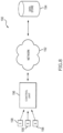
- FIG. 5 is a diagram of communicative components of an automated hydraulic fracturing system with a central control center, in accordance with embodiments of the present disclosure.
- FIG. 6 is a flow chart of an embodiment of an automated hydraulic fracturing method, in accordance with embodiments of the present disclosure.
- FIG. 7 is a flow chart of an embodiment of a method of controlling an automated hydraulic fracturing system, in accordance with embodiments of the present disclosure.
- FIG. 8 is a block diagram of an embodiment of a control system of an automated hydraulic fracturing system, in accordance with embodiments of the present disclosure.
- orientation or direction are made with reference to the illustrated embodiments and are not intended to be limiting or exclude other orientations or directions. Additionally, recitations of steps of a method should be understood as being capable of being performed in any order unless specifically stated otherwise. Furthermore, the steps may be performed in series or in parallel unless specifically stated otherwise.
- FIG. 1 is a schematic representation of an embodiment of a hydraulic fracturing system 10 positioned at a well site 12 .
- pump trucks 14 which make up a pumping system 16 , are used to pressurize a fracturing fluid solution for injection into a wellhead 18 .
- a hydration unit 20 receives fluid from a fluid source 22 via a line, such as a tubular, and also receives additives from an additive source 24 .
- the fluid is water and the additives are mixed together and transferred to a blender unit 26 where proppant from a proppant source 28 may be added to form the fracturing fluid solution (e.g., fracturing fluid) which is transferred to the pumping system 16 .
- fracturing fluid solution e.g., fracturing fluid
- a distribution system 30 receives the fracturing fluid solution for injection into the wellhead 18 .
- the distribution system 30 consolidates the fracturing fluid solution from each of the pump trucks 14 (for example, via common manifold for distribution of fluid to the pumps) and includes discharge piping 32 (which may be a series of discharge lines or a single discharge line) coupled to the wellhead 18 . In this manner, pressurized solution for hydraulic fracturing may be injected into the wellhead 18 .
- one or more sensors 34 , 36 are arranged throughout the hydraulic fracturing system 10 . In embodiments, the sensors 34 transmit flow data to a data van 38 for collection and analysis, among other things.
- FIG. 2 is a detailed schematic representation of an automated hydraulic fracturing system 40 , that can be used for pressurizing a wellbore 42 to create fractures 44 in a subterranean formation 46 that surrounds the wellbore 42 .
- a hydration unit 48 that receives fluid from a fluid source 50 via line 52 , and also selectively receives additives from an additive source 54 via line 56 .
- Additive source 54 can be separate from the hydration unit 48 as a stand-alone unit, or can be included as part of the same unit as the hydration unit 48 .
- the fluid which in one example is water, is mixed inside of the hydration unit 48 with the additives.
- the fluid and additives are mixed over a period of time, to allow for uniform distribution of the additives within the fluid.
- the fluid and additive mixture is transferred to a blender unit 58 via line 60 .
- a proppant source 62 contains proppant, which is delivered to the blender unit 58 as represented by line 64 , where line 64 can be a conveyer.
- the proppant and fluid/additive mixture are combined to form a fracturing fluid, which is then transferred to a fracturing pump system 66 via line 68 ; thus fluid in line 68 includes the discharge of blender unit 58 which is the suction (or boost) for the fracturing pump system 66 .
- Discharge piping 42 connects discharge of pump system 66 with wellhead assembly 71 and provides a conduit for the fracturing fluid between the pump system 66 and the wellhead assembly 71 .
- hoses or other connections can be used to provide a conduit for the fracturing fluid between the pump system 66 and the wellhead assembly 71 .
- any type of fluid can be pressurized by the fracturing pump system 66 to form injection fracturing fluid that is then pumped into the wellbore 42 for fracturing the formation 44 , and is not limited to fluids having chemicals or proppant.
- the output or low voltage side of the transformer 56 connects to a power bus 90 , lines 92 , 94 , 96 , 98 , 100 , and 101 connect to power bus 90 and deliver electricity to electrically powered components of the system 40 . More specifically, line 92 connects fluid source 20 to bus 90 , line 94 connects additive source 24 to bus 90 , line 96 connects hydration unit 18 to bus 90 , line 98 connects proppant source 62 to bus 90 , line 100 connects blender unit 28 to bus 90 , and line 101 connects bus 90 to an optional variable frequency drive (“VFD”) 102 .
- Line 103 connects VFD 102 to motor 69 . In one example, VFD 102 can be used to control operation of motor 69 , and thus also operation of pump 66 .
- additive source 54 contains ten or more chemical pumps for supplementing the existing chemical pumps on the hydration unit 48 and blender unit 58 .
- Chemicals from the additive source 54 can be delivered via lines 56 to either the hydration unit 48 and/or the blender unit 58 .
- the elements of the system 40 are mobile and can be readily transported to a wellsite adjacent the wellbore 42 , such as on trailers or other platforms equipped with wheels or tracks.
- one or more instrumentation devices 104 such as various types of sensors 106 and controllers 108 are arranged throughout the hydraulic fracturing system 40 and coupled to one or more of the aforementioned components, including any of the wellhead assembly 71 , pump 66 , blender unit 58 , proppant source 62 , hydration unit 48 , additive source 54 , fluid source 50 , generator 80 , turbine 74 , fuel source 76 , any deliveries lines, and various other equipment used in the hydraulic fracturing system 40 , not all of which are explicitly described herein for sake of brevity.
- the instrumentation 104 may include various sensors, actuators, and/or controllers, which may be different for different components.
- the instrumentation devices 104 may include hardware features such as, low pressure transducer (low and high frequency), high pressure transducers (low and high frequency), low frequency accelerometers, high frequency accelerometers, temperature sensors, external mounted flow meters such as doppler and sonar sensors, magnetic flow meters, turbine flow meters, proximity probes and sensors, speed sensors, tachometers, capacitive, doppler, inductive, optical, radar, ultrasonic, fiber optic, and hall effect sensors, transmitters and receivers, stroke counters, GPS location monitoring, fuel consumption, load cells, PLCs, and timers.
- the instrumentation devices may be installed on the components and dispersed in various locations.
- the components may also include communication means that enable all the sensor packages, actuation devices, and equipment components to communicate with each other allowing for real time conditional monitoring. This would allow equipment to adjust rates, pressure, operating conditions such as engine, transmission, power ends RPMs, sand storage compartment gates, valves, and actuators, sand delivery belts and shoots, water storage compartments gates, valves, and actuators, water delivery lines and hoses, individual fracture pump's rates as well as collective system rates, blender hydraulics such as chemical pumps, liquid and dry, fan motors for cooling packages, blender discharge pumps, electric and variable frequency powered chemical pumps and auger screws, suction and discharge manifold meters, valves, and actuators.
- Equipment can prevent failures, reduce continual damage, and control when it is allowed and not allowed to continue to operate based on live and continuous data readings.
- Each component may be able to provide troubleshooting codes and alerts that more specifically narrow down the potential causes of issues. This allows technicians to more effectively service equipment, or for troubleshooting or other processes to be initialized automatically.
- Conditional monitoring will identify changes in system components and will be able to direct, divert, and manage all components so that each is performing its job the most efficiently
- the sensors may transmit data to a data van 38 for collection and analysis, among other things.
- the sensors may transmit data to other components, to the central processing unit, or to devices and control units remote from the site.
- the communications between components, sensors, and control devices may be wired, wireless, or a combination of both.
- Communication means may include fiber optics, electrical cables, WiFi, Bluetooth, radio frequency, and other cellular, nearfield, Internet-based, or other networked communication means.
- the features of the present disclosure may allow for remote monitoring and control from diverse location, not solely the data van 68 .
- Fracturing control may be integrated in with the sensor and monitoring packages 104 to allow for automated action to be taken when/if needed.
- Equipment may be able to determine issues or failures on its own, then relay that message with a specified code and alarm.
- Equipment may also be in control to shut itself down to prevent failures from occurring.
- Equipment may monitor itself as well as communicate with the system as a whole. This may allow whole system to control equipment and processes so that each and every component is running at its highest efficiency, sand, water, chemical, blenders, pumps, and low and high pressure flow lines.
- Features of the present disclosure may capture, display, and store data, which may be visible locally and remotely. The data may be accessible live during the data collection and historical data may also be available. Each component to this system can be tested individually with simulation as well as physical function testing.
- sand storage and delivery to the blender can be monitored with load cells, sonar sensors and tachometers to determine storage amounts, hopper levels, auger delivery to the tub.
- Pump efficiencies may be monitored with flow sensors, accelerometers, pressure transducer and tachometers to optimize boost and rate while minimizing harmful conditions such as cavitation or over rating. Failure modes such as wash outs, cutting, valve and/or seat failures, packing issues and supply blockage can be captured and then prevented.
- Flow lines, both suction supply and discharge can be monitored with flow meters to distribute and optimize flow rates and velocities while preventing over pumping scenarios.
- instrumentation devices 104 can be imbedded, mounted, located in various locations such as in line with flow vessels like hoses, piping, manifolds, placed one pump components such as fluid ends, power ends, transmission, engines, and any component within these individual pieces, mounted external to piping and flow vessels, mounted on under or above sand and water storage containers.
- Blender hoppers could be duel equipped with hopper proximity level sensors as well as a load cell to determine amount of sand in the hopper at any given time.
- FIG. 3 illustrates an example fracturing pump system 109 , in accordance with example embodiments.
- the fracturing pump system 109 includes instrumented components, including motors 114 , a variable frequency drive (VFD) 115 , pumps 110 , a power end, and a fluid end.
- the fluid end may further include instrumented components such as packings, valves, seats, stay rod bolts, suction manifold, suction hoses, and discharge flow iron.
- Example hardware devices include low pressure transducer (low and high frequency), high pressure transducers (low and high frequency), low frequency accelerometers, high frequency accelerometers, temperature sensors, external mounted flow meters such as doppler and sonar sensors, magnetic flow meters, turbine flow meters, proximity probes and sensors, speed sensors, tachometers, capacitive, doppler, inductive, optical, radar, ultrasonic, fiber optic, and hall effect sensors, transmitters and receivers, stroke counters, gps location monitoring, fuel consumption, PLCs, and timers.
- the system may be attached to a trailer 112 or a skid.
- this may allow equipment to adjust rates, pressure, operating conditions such as engine, transmission, power end rotations per minute (RPMs), valves, actuators, individual fracturing pump rates as well as collective system rates, fan motors for cooling packages, electric and variable frequency drive (VFD) powered electric motors for pumps, suction and discharge manifold meters, valves, and actuators.
- Equipment can prevent failures, reduce continual damage, and control operation based on live and continuous data readings.
- Present systems and techniques may improve the operating efficiencies for each individual component and the system as a whole.
- pump efficiencies can be monitored with flow sensors, accelerometers, pressure transducer and tachometers to optimize boost and rate while minimizing harmful conditions such as cavitation or over rating.
- Failure modes such as wash outs, cutting, valve failures, seat failures, packing issues and supply blockage, can be captured and then prevented.
- Flow lines, both suction supply and discharge can be monitored with flow meters to distribute and optimize flow rates and velocities while preventing over pumping scenarios.
- feedback loops of readings from blender to supply manifolds and to pumps can work with each other to optimize pressure and flow.
- an individual pump may be dropped from operation to prevent further failures.
- the system as a whole may automatically select the best pump(s) to make up for the dropped pump.
- Power ends may keep track of stroke counts and pumping hours. This data may be accompanied with maintenance logs which may help determine schedules and maintenance procedures.
- transmissions may be monitored for each individual gear, duration and load may be logged as well as temperature. If any of these various components were to indicate an alarm that would be detrimental to the equipment, the signal from that sensor may relay the message to shut the entire pump down.
- FIG. 4 includes a diagram 120 illustrating a connected automated fracturing system, in accordance with various embodiments.
- one or more components 42 of a fracturing system such as a pump 122 , blender 124 , hydration unit 126 , fluid source 128 , proppant source 130 , additive source 132 , and one or more other components 134 , may include communication devices for transmitting and receiving data with each other over a communication network 136 .
- the components include processors that analyze the data received from one or more of the other components and automatically controls one or more aspects of that component.
- the communication network 136 may include various types of wired or wireless communication protocols, or a combination of wired and wireless communications.
- the connected automated fracturing system further includes one or more of a plurality of components including a manifold, a manifold trailer, a discharge piping, flow lines, conveyance devices, a turbine, a motor, a variable frequency drive, a generator, or a fuel source. Sensors and control devices may be integrated into the one or more of these components, allowing these components to communicate with the rest of the system.
- FIG. 5 includes a diagram 140 illustrating a communications network of the automated fracturing system, in accordance with various embodiments.
- one or more hydraulic fracturing components 148 may be communicative with each other via a communication network 150 such as described above with respect to FIG. 4 .
- the components 148 may also be communicative with a control center 142 over the communication network 150 .
- the control center 142 may be instrumented into the hydraulic fracturing system or a component.
- the control center 142 may be onsite, in a data van, or located remotely.
- a hydraulic fracturing system includes a plurality of pumps positioned at a wellsite and configured to pressurize a fracturing fluid, a distribution system fluidly coupled to receive and consolidate fracturing fluid from the plurality of pumps for injection into a wellhead.
- the hydraulic fracturing system further includes a control system, which includes a plurality of sensing devices configured to measure one or more parameters of the plurality of pumps and the distribution system.
- the control system also includes one or more processing device configured to receive and analyze the one or more parameters measured by the plurality of sensing devices and generate control instructions based at least in part on the one or more parameters.
- the control system further includes one or more control device configured to receive the control instructions and control one or more aspects of the plurality of pumps or the distribution system based on the control instructions.
- the one or more sensing device are installed on the plurality of pumps and the distribution system, and include at least one of flow sensors, accelerometers, pressure transducer, or tachometers.
- the plurality of pumps or the distribution system may include at least one of a gate, valve, actuator, motor, suction pipe, discharge pipe, engine, transmission, or temperature regulation device, controllable via the one or more control device.
- the system further includes a suction line through which fracturing fluid is supplied and a discharge line through which fracturing fluid is discharged, and the plurality of sensing devices includes one or more flow sensors configured to measure flow through the suction line and the discharge line.
- the system may also include one or more blenders configured to mix together one or more materials to form the fracturing fluid, wherein the fracturing fluid is provided from the blender to the plurality of pumps via a manifold, wherein the plurality of sensing devices includes one or more pressure or flow sensors for measuring flow and/or pressure conditions at the one or more blenders, the manifold, the plurality of pumps and the distribution system.
- the one or more control device is configured to control the one or more blenders, the manifold, the plurality of pumps and the distribution system based on the flow and/or pressure conditions.
- FIG. 6 is a flow chart of an embodiment of an automated hydraulic fracturing method 160 , in accordance with example embodiments. It should be noted that the method may include additional steps, fewer steps, and differently ordered steps than illustrated in this example.
- a fracturing fluid is provided 162 to a plurality of pumps, and the fracturing fluid is pumped 164 into a distribution system.
- the fracturing fluid is then injected 166 into a well via a wellhead.
- One or more parameters of the plurality of pumps, the distribution system, or the wellhead is measured 168 via a plurality of sensing devices instrumented thereon.
- Automated instructions are then generated for one or more control devices based at least in part on the one or more parameters, and one or more functions of the plurality of pumps, the distribution system, or the wellhead can be controlled based at least in part on the automated instructions.
- the method 160 also includes detecting that a first parameter of the one or more parameters is outside of an acceptable threshold, in which the first parameter is associated with a first pump of the plurality of pumps, and automatically adjusting or turning off the first pump. In some embodiments, the method 160 also includes adjusting one or more of the other pumps in the plurality of pumps to compensate for the first pump. In some embodiments, the method 160 also includes selecting the one or more of the other pumps to adjust based at least in part on the conditions of the other pumps as indicated by one or more of the one or more parameters. In one or more embodiments, the method 160 also includes determining that the one or more parameters are indicative of a potential failure condition; and determining a source of the potential failure condition.
- the method 160 also includes generating an alert or notification indicative of the potential failure condition and the source. In some embodiments, the method 160 also includes logging operation data including a number of strokes and pumping hours performed by a pump of the plurality of pumps, and determining a maintenance schedule based at least in part on the operation data.
- the hydraulic fracturing system may include other components, such as a turbine, a generator, a hydration unit, a distribution system, a fuel source, or a wellhead, among others. These components may also be instrumented with sensors that measures at least one parameter associated with the turbine, the generator, the hydration unit, the distribution system, the fuel source, or the wellhead. These components may also include controllers, which control at least one aspect of the turbine, the generator, the hydration unit, the distribution system, the fuel source, or the wellhead, based at least in part on the automated instructions.
- the hydraulic fracturing system includes a plurality of pumps and a distribution system, in which fracturing fluid is provided from the blender to the plurality of pumps, the fracturing fluid is provided from the plurality of pumps to the distribution system, and the fracturing fluid is injected from the distribution system into the wellbore.
- the individual pressure at each pump may be automatically adjusted based on the automated instructions.
- the combined or overall pump rate of the plurality of pumps may also be controlled, and the rate at the distribution system may also be controlled via the automated instructions.
- FIG. 7 illustrates a method 180 of controlling an automated fracturing system, in accordance with various embodiments.
- a first data is received 182 from a first sensing device of a pump system of a hydraulic fracturing system.
- the first data may be indicative of a condition of the pump system, such as a flow rate, pump efficiency, temperature, pressure, among others.
- Second data may be received 184 from a second sensing device of a blender system of the hydraulic fracturing system.
- the blender system mixes together materials such as proppant and a fluid to form a fracturing fluid and delivers the fracturing fluid to the pump system.
- the second data may be indicative of a condition of the blender system.
- Automated instructions for one or more control devices of the pump system or the blender system is generated based at least in part on the first and second data.
- one or more functions of the plurality of the pump system or the blender system is controlled based at least in part on the automated instructions.
- the pump system includes one or more pumps and a distribution system that receives and consolidates the fracturing fluid from the one or more pumps for injection into a wellhead.
- the method 180 also includes controlling one or more functions of the distribution system based on the automated instructions.
- the pump system includes a plurality of pumps, and the first data includes measurements of each of the plurality of pumps.
- the method 180 may also include controlling one or more of the plurality of pumps individually based on the automated instructions.
- the method 180 may further include detecting that a measurement associated with a first pump of the plurality of pumps is outside of an acceptable threshold, and automatically taking the first pump offline in response to the detection.
- the method may further include adjusting one or more of the other pumps in the plurality of pumps to compensate for taking the first pump offline.
- FIG. 8 is a block diagram of an embodiment of a control system 190 for receiving, analyzing, and storing information from the well site.
- sensors 198 are arranged at the well site and may transmit data to a control unit 196 for evaluation and potential adjustments to operating parameters of equipment at the well site.
- the control unit 196 may be communicatively coupled to a network 192 , such as the Internet, that can access a data store 194 , such as a cloud storage server. Accordingly, in embodiments, data from the sensors 198 is transmitted to the control unit 196 (which may be located on a component, within a data van, or remotely) and is stored locally.
- control unit 196 may upload the data from the sensors 198 along with other data, to the data store 194 via the network 192 .
- data from previous pumping operations or different sensors may be utilized to adjust various aspects of the hydraulic fracturing operation as needed.
- the flow data from the sensor 198 may be coupled with information from the sensors 198 (such as the vibration sensor, gear sensors, RPM sensors, pressure sensors, etc.) to provide diagnostics with information from the data store 194 .
- previous data may be used as training data for a machine learning model for predicting various control parameters of a present operation.
- the data store 194 includes information of the equipment used at the well site. It should be appreciated that, in various embodiments, information from the data store 194 may be stored in local storage, for example in storage within a data can, and as a result, communication over the network 192 to the remote data store 194 may not be used. For example, in various embodiments, drilling operations may be conducted at remote locations where Internet data transmission may be slow or unreliable. As a result, information from the data store 194 may be downloaded and stored locally at the data van before the operation, thereby providing access to the information for evaluation of operation conditions at the well site.
Abstract
Description
Claims (20)
Priority Applications (2)
| Application Number | Priority Date | Filing Date | Title |
|---|---|---|---|
| US16/876,929 US11808125B2 (en) | 2017-10-25 | 2020-05-18 | Smart fracturing system and method |
| US18/503,810 US20240076975A1 (en) | 2017-10-25 | 2023-11-07 | Smart fracturing system and method |
Applications Claiming Priority (3)
| Application Number | Priority Date | Filing Date | Title |
|---|---|---|---|
| US201762577056P | 2017-10-25 | 2017-10-25 | |
| US16/170,695 US10655435B2 (en) | 2017-10-25 | 2018-10-25 | Smart fracturing system and method |
| US16/876,929 US11808125B2 (en) | 2017-10-25 | 2020-05-18 | Smart fracturing system and method |
Related Parent Applications (1)
| Application Number | Title | Priority Date | Filing Date |
|---|---|---|---|
| US16/170,695 Continuation US10655435B2 (en) | 2017-10-25 | 2018-10-25 | Smart fracturing system and method |
Related Child Applications (1)
| Application Number | Title | Priority Date | Filing Date |
|---|---|---|---|
| US18/503,810 Continuation US20240076975A1 (en) | 2017-10-25 | 2023-11-07 | Smart fracturing system and method |
Publications (2)
| Publication Number | Publication Date |
|---|---|
| US20200386077A1 US20200386077A1 (en) | 2020-12-10 |
| US11808125B2 true US11808125B2 (en) | 2023-11-07 |
Family
ID=66171014
Family Applications (3)
| Application Number | Title | Priority Date | Filing Date |
|---|---|---|---|
| US16/170,695 Active US10655435B2 (en) | 2017-10-25 | 2018-10-25 | Smart fracturing system and method |
| US16/876,929 Active US11808125B2 (en) | 2017-10-25 | 2020-05-18 | Smart fracturing system and method |
| US18/503,810 Pending US20240076975A1 (en) | 2017-10-25 | 2023-11-07 | Smart fracturing system and method |
Family Applications Before (1)
| Application Number | Title | Priority Date | Filing Date |
|---|---|---|---|
| US16/170,695 Active US10655435B2 (en) | 2017-10-25 | 2018-10-25 | Smart fracturing system and method |
Family Applications After (1)
| Application Number | Title | Priority Date | Filing Date |
|---|---|---|---|
| US18/503,810 Pending US20240076975A1 (en) | 2017-10-25 | 2023-11-07 | Smart fracturing system and method |
Country Status (5)
| Country | Link |
|---|---|
| US (3) | US10655435B2 (en) |
| AR (1) | AR114805A1 (en) |
| CA (1) | CA3080317A1 (en) |
| SA (1) | SA520411837B1 (en) |
| WO (1) | WO2019084283A1 (en) |
Families Citing this family (83)
| Publication number | Priority date | Publication date | Assignee | Title |
|---|---|---|---|---|
| US9140110B2 (en) | 2012-10-05 | 2015-09-22 | Evolution Well Services, Llc | Mobile, modular, electrically powered system for use in fracturing underground formations using liquid petroleum gas |
| US11255173B2 (en) | 2011-04-07 | 2022-02-22 | Typhon Technology Solutions, Llc | Mobile, modular, electrically powered system for use in fracturing underground formations using liquid petroleum gas |
| US11708752B2 (en) | 2011-04-07 | 2023-07-25 | Typhon Technology Solutions (U.S.), Llc | Multiple generator mobile electric powered fracturing system |
| US9970278B2 (en) | 2012-11-16 | 2018-05-15 | U.S. Well Services, LLC | System for centralized monitoring and control of electric powered hydraulic fracturing fleet |
| US10407990B2 (en) | 2012-11-16 | 2019-09-10 | U.S. Well Services, LLC | Slide out pump stand for hydraulic fracturing equipment |
| US9893500B2 (en) | 2012-11-16 | 2018-02-13 | U.S. Well Services, LLC | Switchgear load sharing for oil field equipment |
| US11449018B2 (en) | 2012-11-16 | 2022-09-20 | U.S. Well Services, LLC | System and method for parallel power and blackout protection for electric powered hydraulic fracturing |
| US10232332B2 (en) | 2012-11-16 | 2019-03-19 | U.S. Well Services, Inc. | Independent control of auger and hopper assembly in electric blender system |
| US9410410B2 (en) | 2012-11-16 | 2016-08-09 | Us Well Services Llc | System for pumping hydraulic fracturing fluid using electric pumps |
| US10020711B2 (en) | 2012-11-16 | 2018-07-10 | U.S. Well Services, LLC | System for fueling electric powered hydraulic fracturing equipment with multiple fuel sources |
| US10254732B2 (en) | 2012-11-16 | 2019-04-09 | U.S. Well Services, Inc. | Monitoring and control of proppant storage from a datavan |
| US9995218B2 (en) | 2012-11-16 | 2018-06-12 | U.S. Well Services, LLC | Turbine chilling for oil field power generation |
| US10036238B2 (en) | 2012-11-16 | 2018-07-31 | U.S. Well Services, LLC | Cable management of electric powered hydraulic fracturing pump unit |
| US9745840B2 (en) | 2012-11-16 | 2017-08-29 | Us Well Services Llc | Electric powered pump down |
| US9650879B2 (en) | 2012-11-16 | 2017-05-16 | Us Well Services Llc | Torsional coupling for electric hydraulic fracturing fluid pumps |
| US11476781B2 (en) | 2012-11-16 | 2022-10-18 | U.S. Well Services, LLC | Wireline power supply during electric powered fracturing operations |
| US10119381B2 (en) | 2012-11-16 | 2018-11-06 | U.S. Well Services, LLC | System for reducing vibrations in a pressure pumping fleet |
| CA2987665C (en) | 2016-12-02 | 2021-10-19 | U.S. Well Services, LLC | Constant voltage power distribution system for use with an electric hydraulic fracturing system |
| US11624326B2 (en) | 2017-05-21 | 2023-04-11 | Bj Energy Solutions, Llc | Methods and systems for supplying fuel to gas turbine engines |
| CA3078509A1 (en) | 2017-10-05 | 2019-04-11 | U.S. Well Services, LLC | Instrumented fracturing slurry flow system and method |
| US10408031B2 (en) | 2017-10-13 | 2019-09-10 | U.S. Well Services, LLC | Automated fracturing system and method |
| AR114805A1 (en) * | 2017-10-25 | 2020-10-21 | U S Well Services Llc | INTELLIGENT FRACTURING METHOD AND SYSTEM |
| US10648311B2 (en) | 2017-12-05 | 2020-05-12 | U.S. Well Services, LLC | High horsepower pumping configuration for an electric hydraulic fracturing system |
| CA3084596A1 (en) | 2017-12-05 | 2019-06-13 | U.S. Well Services, LLC | Multi-plunger pumps and associated drive systems |
| US11649817B2 (en) * | 2018-01-23 | 2023-05-16 | Schlumberger Technology Corporation | Operating multiple fracturing pumps to deliver a smooth total flow rate transition |
| CA3090408A1 (en) * | 2018-02-05 | 2019-08-08 | U.S. Well Services, LLC | Microgrid electrical load management |
| US11035207B2 (en) | 2018-04-16 | 2021-06-15 | U.S. Well Services, LLC | Hybrid hydraulic fracturing fleet |
| US11852133B2 (en) * | 2018-04-27 | 2023-12-26 | Ameriforge Group Inc. | Well service pump power system and methods |
| US11211801B2 (en) | 2018-06-15 | 2021-12-28 | U.S. Well Services, LLC | Integrated mobile power unit for hydraulic fracturing |
| US10648270B2 (en) | 2018-09-14 | 2020-05-12 | U.S. Well Services, LLC | Riser assist for wellsites |
| US11208878B2 (en) | 2018-10-09 | 2021-12-28 | U.S. Well Services, LLC | Modular switchgear system and power distribution for electric oilfield equipment |
| CA3118885A1 (en) * | 2018-11-05 | 2020-05-14 | Nan MU | Fracturing operations pump fleet balance controller |
| US11230917B2 (en) * | 2018-11-13 | 2022-01-25 | Vault Pressure Control Llc | Surface completion system for operations and monitoring |
| WO2020142638A1 (en) * | 2019-01-04 | 2020-07-09 | Commando Pressure Control Llc | Methods and systems associated with an automated zipper manifold |
| US11578577B2 (en) | 2019-03-20 | 2023-02-14 | U.S. Well Services, LLC | Oversized switchgear trailer for electric hydraulic fracturing |
| US11728709B2 (en) | 2019-05-13 | 2023-08-15 | U.S. Well Services, LLC | Encoderless vector control for VFD in hydraulic fracturing applications |
| US11560845B2 (en) | 2019-05-15 | 2023-01-24 | Bj Energy Solutions, Llc | Mobile gas turbine inlet air conditioning system and associated methods |
| CA3138942A1 (en) * | 2019-05-17 | 2020-11-26 | Fmc Technologies, Inc. | System and method for an automated and intelligent frac pad |
| US11674384B2 (en) | 2019-05-20 | 2023-06-13 | Schlumberger Technology Corporation | Controller optimization via reinforcement learning on asset avatar |
| US11927087B2 (en) | 2019-07-26 | 2024-03-12 | Typhon Technology Solutions (U.S.), Llc | Artificial intelligence based hydraulic fracturing system monitoring and control |
| US11542786B2 (en) | 2019-08-01 | 2023-01-03 | U.S. Well Services, LLC | High capacity power storage system for electric hydraulic fracturing |
| US10961914B1 (en) | 2019-09-13 | 2021-03-30 | BJ Energy Solutions, LLC Houston | Turbine engine exhaust duct system and methods for noise dampening and attenuation |
| US11002189B2 (en) | 2019-09-13 | 2021-05-11 | Bj Energy Solutions, Llc | Mobile gas turbine inlet air conditioning system and associated methods |
| US11015594B2 (en) | 2019-09-13 | 2021-05-25 | Bj Energy Solutions, Llc | Systems and method for use of single mass flywheel alongside torsional vibration damper assembly for single acting reciprocating pump |
| CA3092865C (en) | 2019-09-13 | 2023-07-04 | Bj Energy Solutions, Llc | Power sources and transmission networks for auxiliary equipment onboard hydraulic fracturing units and associated methods |
| CA3092829C (en) | 2019-09-13 | 2023-08-15 | Bj Energy Solutions, Llc | Methods and systems for supplying fuel to gas turbine engines |
| US10989180B2 (en) | 2019-09-13 | 2021-04-27 | Bj Energy Solutions, Llc | Power sources and transmission networks for auxiliary equipment onboard hydraulic fracturing units and associated methods |
| US11555756B2 (en) | 2019-09-13 | 2023-01-17 | Bj Energy Solutions, Llc | Fuel, communications, and power connection systems and related methods |
| US10895202B1 (en) | 2019-09-13 | 2021-01-19 | Bj Energy Solutions, Llc | Direct drive unit removal system and associated methods |
| US11015536B2 (en) | 2019-09-13 | 2021-05-25 | Bj Energy Solutions, Llc | Methods and systems for supplying fuel to gas turbine engines |
| CA3197583A1 (en) | 2019-09-13 | 2021-03-13 | Bj Energy Solutions, Llc | Fuel, communications, and power connection systems and related methods |
| US10815764B1 (en) | 2019-09-13 | 2020-10-27 | Bj Energy Solutions, Llc | Methods and systems for operating a fleet of pumps |
| US11009162B1 (en) | 2019-12-27 | 2021-05-18 | U.S. Well Services, LLC | System and method for integrated flow supply line |
| US20210199110A1 (en) * | 2019-12-31 | 2021-07-01 | U.S. Well Services, LLC | Systems and methods for fluid end early failure prediction |
| US11499547B2 (en) | 2020-02-27 | 2022-11-15 | Caterpillar Inc. | Hydraulic fracturing pump health monitor |
| US11708829B2 (en) | 2020-05-12 | 2023-07-25 | Bj Energy Solutions, Llc | Cover for fluid systems and related methods |
| US10968837B1 (en) | 2020-05-14 | 2021-04-06 | Bj Energy Solutions, Llc | Systems and methods utilizing turbine compressor discharge for hydrostatic manifold purge |
| US11428165B2 (en) | 2020-05-15 | 2022-08-30 | Bj Energy Solutions, Llc | Onboard heater of auxiliary systems using exhaust gases and associated methods |
| US11208880B2 (en) | 2020-05-28 | 2021-12-28 | Bj Energy Solutions, Llc | Bi-fuel reciprocating engine to power direct drive turbine fracturing pumps onboard auxiliary systems and related methods |
| US10961908B1 (en) | 2020-06-05 | 2021-03-30 | Bj Energy Solutions, Llc | Systems and methods to enhance intake air flow to a gas turbine engine of a hydraulic fracturing unit |
| US11109508B1 (en) | 2020-06-05 | 2021-08-31 | Bj Energy Solutions, Llc | Enclosure assembly for enhanced cooling of direct drive unit and related methods |
| US11208953B1 (en) | 2020-06-05 | 2021-12-28 | Bj Energy Solutions, Llc | Systems and methods to enhance intake air flow to a gas turbine engine of a hydraulic fracturing unit |
| US10954770B1 (en) | 2020-06-09 | 2021-03-23 | Bj Energy Solutions, Llc | Systems and methods for exchanging fracturing components of a hydraulic fracturing unit |
| US11111768B1 (en) | 2020-06-09 | 2021-09-07 | Bj Energy Solutions, Llc | Drive equipment and methods for mobile fracturing transportation platforms |
| US11022526B1 (en) | 2020-06-09 | 2021-06-01 | Bj Energy Solutions, Llc | Systems and methods for monitoring a condition of a fracturing component section of a hydraulic fracturing unit |
| US11066915B1 (en) | 2020-06-09 | 2021-07-20 | Bj Energy Solutions, Llc | Methods for detection and mitigation of well screen out |
| US11028677B1 (en) | 2020-06-22 | 2021-06-08 | Bj Energy Solutions, Llc | Stage profiles for operations of hydraulic systems and associated methods |
| US11939853B2 (en) | 2020-06-22 | 2024-03-26 | Bj Energy Solutions, Llc | Systems and methods providing a configurable staged rate increase function to operate hydraulic fracturing units |
| US11125066B1 (en) | 2020-06-22 | 2021-09-21 | Bj Energy Solutions, Llc | Systems and methods to operate a dual-shaft gas turbine engine for hydraulic fracturing |
| US11933153B2 (en) | 2020-06-22 | 2024-03-19 | Bj Energy Solutions, Llc | Systems and methods to operate hydraulic fracturing units using automatic flow rate and/or pressure control |
| US11466680B2 (en) | 2020-06-23 | 2022-10-11 | Bj Energy Solutions, Llc | Systems and methods of utilization of a hydraulic fracturing unit profile to operate hydraulic fracturing units |
| US11473413B2 (en) | 2020-06-23 | 2022-10-18 | Bj Energy Solutions, Llc | Systems and methods to autonomously operate hydraulic fracturing units |
| US11220895B1 (en) | 2020-06-24 | 2022-01-11 | Bj Energy Solutions, Llc | Automated diagnostics of electronic instrumentation in a system for fracturing a well and associated methods |
| US11149533B1 (en) | 2020-06-24 | 2021-10-19 | Bj Energy Solutions, Llc | Systems to monitor, detect, and/or intervene relative to cavitation and pulsation events during a hydraulic fracturing operation |
| US11193360B1 (en) | 2020-07-17 | 2021-12-07 | Bj Energy Solutions, Llc | Methods, systems, and devices to enhance fracturing fluid delivery to subsurface formations during high-pressure fracturing operations |
| CN111852430A (en) * | 2020-08-04 | 2020-10-30 | 东北石油大学 | Fracturing fracture-making experimental device for simulating injection-production relation of multiple injection-production well pattern |
| US20240003235A1 (en) * | 2020-10-30 | 2024-01-04 | Schlumberger Technology Corporation | Fracturing operation system |
| US11639654B2 (en) | 2021-05-24 | 2023-05-02 | Bj Energy Solutions, Llc | Hydraulic fracturing pumps to enhance flow of fracturing fluid into wellheads and related methods |
| US11408417B1 (en) | 2021-09-10 | 2022-08-09 | Halliburton Energy Services, Inc. | Automatic selection and control of pumps for well stimulation operations |
| CN113653479A (en) * | 2021-09-16 | 2021-11-16 | 成都鹦鹉螺大数据科技有限公司 | Fracturing construction internet of things system |
| WO2023245636A1 (en) * | 2022-06-24 | 2023-12-28 | 烟台杰瑞石油装备技术有限公司 | Fracturing control method and fracturing system |
| US11955782B1 (en) | 2022-11-01 | 2024-04-09 | Typhon Technology Solutions (U.S.), Llc | System and method for fracturing of underground formations using electric grid power |
| CN115680598B (en) * | 2023-01-03 | 2023-04-07 | 四川宏华电气有限责任公司 | Electric fracturing operation system and method for coal mine underground gas treatment |
Citations (142)
| Publication number | Priority date | Publication date | Assignee | Title |
|---|---|---|---|---|
| US2976025A (en) | 1958-10-16 | 1961-03-21 | Air Placement Equipment Compan | Combined mixer and conveyor |
| US3878884A (en) | 1973-04-02 | 1975-04-22 | Cecil B Raleigh | Formation fracturing method |
| US4411313A (en) | 1981-10-19 | 1983-10-25 | Liquid Level Lectronics, Inc. | Pump |
| US4538916A (en) | 1984-06-20 | 1985-09-03 | Zimmerman Harold M | Motor mounting arrangement on a mixing auger |
| US4601629A (en) | 1984-06-20 | 1986-07-22 | Zimmerman Harold M | Fine and coarse aggregates conveying apparatus |
| US4768884A (en) | 1987-03-03 | 1988-09-06 | Elkin Luther V | Cement mixer for fast setting materials |
| US5114239A (en) | 1989-09-21 | 1992-05-19 | Halliburton Company | Mixing apparatus and method |
| US5334899A (en) | 1991-09-30 | 1994-08-02 | Dymytro Skybyk | Polyphase brushless DC and AC synchronous machines |
| US5439066A (en) | 1994-06-27 | 1995-08-08 | Fleet Cementers, Inc. | Method and system for downhole redirection of a borehole |
| US5486047A (en) | 1995-06-05 | 1996-01-23 | Zimmerman; Harold M. | Mixing auger for concrete trucks |
| US5517822A (en) | 1993-06-15 | 1996-05-21 | Applied Energy Systems Of Oklahoma, Inc. | Mobile congeneration apparatus including inventive valve and boiler |
| US5798596A (en) | 1996-07-03 | 1998-08-25 | Pacific Scientific Company | Permanent magnet motor with enhanced inductance |
| US5813455A (en) | 1997-03-11 | 1998-09-29 | Amoco Coporation | Chemical dispensing system |
| US5950726A (en) | 1996-08-06 | 1999-09-14 | Atlas Tool Company | Increased oil and gas production using elastic-wave stimulation |
| US6035265A (en) | 1997-10-08 | 2000-03-07 | Reliance Electric Industrial Company | System to provide low cost excitation to stator winding to generate impedance spectrum for use in stator diagnostics |
| US6097310A (en) | 1998-02-03 | 2000-08-01 | Baker Hughes Incorporated | Method and apparatus for mud pulse telemetry in underbalanced drilling systems |
| US6121705A (en) | 1996-12-31 | 2000-09-19 | Hoong; Fong Chean | Alternating pole AC motor/generator with two inner rotating rotors and an external static stator |
| US20010000996A1 (en) | 1998-03-06 | 2001-05-10 | Grimland Kristian E. | Multiple tub mobile blender |
| US6273193B1 (en) | 1997-12-16 | 2001-08-14 | Transocean Sedco Forex, Inc. | Dynamically positioned, concentric riser, drilling method and apparatus |
| US6442942B1 (en) | 1999-06-10 | 2002-09-03 | Enhanced Turbine Output Holding, Llc | Supercharging system for gas turbines |
| US20030079875A1 (en) | 2001-08-03 | 2003-05-01 | Xiaowei Weng | Fracture closure pressure determination |
| US6585455B1 (en) | 1992-08-18 | 2003-07-01 | Shell Oil Company | Rocker arm marine tensioning system |
| US6626646B2 (en) | 2001-10-19 | 2003-09-30 | Robert C. Rajewski | Vehicle mounted gas well pumping unit |
| US20040045703A1 (en) | 2002-09-05 | 2004-03-11 | Hooper Robert C. | Apparatus for positioning and stabbing pipe in a drilling rig derrick |
| US6765304B2 (en) | 2001-09-26 | 2004-07-20 | General Electric Co. | Mobile power generation unit |
| US6788022B2 (en) | 2002-10-21 | 2004-09-07 | A. O. Smith Corporation | Electric motor |
| US20050201197A1 (en) | 2004-03-10 | 2005-09-15 | Duell Alan B. | System and method for mixing water and non-aqueous materials using measured water concentration to control addition of ingredients |
| US6985750B1 (en) | 1999-04-27 | 2006-01-10 | Bj Services Company | Wireless network system |
| US20060109141A1 (en) | 2002-09-06 | 2006-05-25 | Songming Huang | Noise attenuation apparatus for borehole telemetry |
| US20080095644A1 (en) | 2006-10-19 | 2008-04-24 | Bidell Equipment Limited Partnership | Mobile wear and tear resistant gas compressor |
| US20080164023A1 (en) | 2005-04-14 | 2008-07-10 | Halliburton Energy Services, Inc. | Method for Servicing a Well Bore Using a Mixing Control System |
| US20080257449A1 (en) | 2007-04-17 | 2008-10-23 | Halliburton Energy Services, Inc. | Dry additive metering into portable blender tub |
| US20080277120A1 (en) | 2007-05-11 | 2008-11-13 | Stinger Wellhead Protection, Inc. | Retrievable frac mandrel and well control stack to facilitate well completion, re-completion or workover and method of use |
| US20090072645A1 (en) | 2007-09-13 | 2009-03-19 | Eric Stephane Quere | Composite electromechanical machines with gear mechanism |
| WO2009046280A1 (en) | 2007-10-05 | 2009-04-09 | Weatherford/Lanb, Inc. | Quintuplex mud pump |
| US7795830B2 (en) | 2005-07-06 | 2010-09-14 | Elckon Limited | Electric motor |
| US20110052423A1 (en) * | 2009-09-03 | 2011-03-03 | Philippe Gambier | Pump Assembly |
| US20110081268A1 (en) | 2009-08-13 | 2011-04-07 | Brian Ochoa | Pump body |
| US20110110793A1 (en) | 2009-11-06 | 2011-05-12 | Edward Leugemors | Suction stabilizer for pump assembly |
| US20120063936A1 (en) | 2010-09-10 | 2012-03-15 | Phoinix Global LLC | Modular fluid end for a multiplex plunger pump |
| US20120112757A1 (en) | 2010-11-10 | 2012-05-10 | Vrankovic Zoran V | Ground Fault Detection and Location System and Method for Motor Drives |
| US20120150455A1 (en) | 2009-08-18 | 2012-06-14 | Franklin Charles M | System and Method for Determining Leaks in a Complex System |
| US20120152716A1 (en) | 2010-12-20 | 2012-06-21 | Hitachi, Ltd. | Switchgear |
| US20130051971A1 (en) | 2011-08-29 | 2013-02-28 | Gene Wyse | Expandable Stowable Platform for Unloading Trucks |
| US20130180722A1 (en) | 2009-12-04 | 2013-07-18 | Schlumberger Technology Corporation | Technique of fracturing with selective stream injection |
| US20130189629A1 (en) | 2008-07-07 | 2013-07-25 | Ronald L. Chandler | Frac water heater and fuel oil heating system |
| US8506267B2 (en) | 2007-09-10 | 2013-08-13 | Schlumberger Technology Corporation | Pump assembly |
| US20130255271A1 (en) | 2012-03-30 | 2013-10-03 | General Electric Company | Fuel Supply System |
| US20130284455A1 (en) | 2012-04-26 | 2013-10-31 | Ge Oil & Gas Pressure Control Lp | Delivery System for Fracture Applications |
| US20130299167A1 (en) | 2012-05-14 | 2013-11-14 | Gasfrac Energy Services Inc. | Hybrid lpg frac |
| US20140095114A1 (en) * | 2012-09-28 | 2014-04-03 | Hubertus V. Thomeer | System And Method For Tracking And Displaying Equipment Operations Data |
| US20140174717A1 (en) | 2012-11-16 | 2014-06-26 | Us Well Services Llc | System for pumping hydraulic fracturing fluid using electric pumps |
| US8763387B2 (en) | 2009-08-10 | 2014-07-01 | Howard K. Schmidt | Hydraulic geofracture energy storage system |
| US8774972B2 (en) * | 2007-05-14 | 2014-07-08 | Flowserve Management Company | Intelligent pump system |
| US8795525B2 (en) | 2008-12-03 | 2014-08-05 | Oasys Water, Inc. | Utility scale osmotic grid storage |
| US20140277772A1 (en) * | 2013-03-14 | 2014-09-18 | Schlumberger Technology Corporation | Fracturing pump identification and communication |
| US20140290768A1 (en) * | 2013-03-27 | 2014-10-02 | Fts International Services, Llc | Frac Pump Isolation Safety System |
| CN104117308A (en) | 2014-07-28 | 2014-10-29 | 丹阳市海信涂料化工厂 | Device for mixing and preparing coating |
| WO2014177346A1 (en) | 2013-05-03 | 2014-11-06 | Siemens Aktiengesellschaft | Power system for a floating vessel |
| CN104196613A (en) | 2014-08-22 | 2014-12-10 | 中石化石油工程机械有限公司第四机械厂 | Cooling device of fracturing truck |
| US20140379300A1 (en) * | 2012-02-02 | 2014-12-25 | Ghd Pty Ltd | Pump efficiency determining system and related method for determining pump efficiency |
| US20150147194A1 (en) | 2012-10-17 | 2015-05-28 | Global Energy Services, Inc. | Segmented fluid end |
| US9051923B2 (en) | 2011-10-03 | 2015-06-09 | Chang Kuo | Dual energy solar thermal power plant |
| US9062545B2 (en) | 2012-06-26 | 2015-06-23 | Lawrence Livermore National Security, Llc | High strain rate method of producing optimized fracture networks in reservoirs |
| US20150233530A1 (en) | 2014-02-20 | 2015-08-20 | Pcs Ferguson, Inc. | Method and system to volumetrically control additive pump |
| US9140105B2 (en) | 2011-10-11 | 2015-09-22 | Lance N. Pattillo | Temporary support device for oil well tubes and method of use |
| US20160006311A1 (en) | 2014-06-19 | 2016-01-07 | Turboroto Inc. | Electric motor, generator and commutator system, device and method |
| US20160032703A1 (en) * | 2012-11-16 | 2016-02-04 | Us Well Services Llc | System for centralized monitoring and control of electric powered hydraulic fracturing fleet |
| US20160102537A1 (en) * | 2014-10-13 | 2016-04-14 | Schlumberger Technology Corporation | Control systems for fracturing operations |
| US9353593B1 (en) | 2015-03-13 | 2016-05-31 | National Oilwell Varco, Lp | Handler for blowout preventer assembly |
| US20160208592A1 (en) * | 2015-01-14 | 2016-07-21 | Us Well Services Llc | System for Reducing Noise in a Hydraulic Fracturing Fleet |
| US20160230660A1 (en) | 2015-02-10 | 2016-08-11 | Univ King Saud | Gas turbine power generator with two-stage inlet air cooling |
| US20160273456A1 (en) | 2013-10-16 | 2016-09-22 | General Electric Company | Gas turbine system and method |
| US20160290114A1 (en) * | 2012-11-16 | 2016-10-06 | Us Well Services Llc | Modular remote power generation and transmission for hydraulic fracturing system |
| US9482086B2 (en) | 2013-09-27 | 2016-11-01 | Well Checked Systems International LLC | Remote visual and auditory monitoring system |
| US20160326853A1 (en) | 2015-05-08 | 2016-11-10 | Schlumberger Technology Corporation | Multiple wellbore perforation and stimulation |
| US9506333B2 (en) | 2013-12-24 | 2016-11-29 | Baker Hughes Incorporated | One trip multi-interval plugging, perforating and fracking method |
| US20170022788A1 (en) * | 2012-11-16 | 2017-01-26 | Us Well Services Llc | Safety indicator lights for hydraulic fracturing pumps |
| US20170030178A1 (en) * | 2012-11-16 | 2017-02-02 | Us Well Services Llc | Electric powered pump down |
| US20170028368A1 (en) * | 2012-11-16 | 2017-02-02 | Us Well Services Llc | Independent control of auger and hopper assembly in electric blender system |
| US20170037717A1 (en) * | 2012-11-16 | 2017-02-09 | Us Well Services Llc | System for Reducing Vibrations in a Pressure Pumping Fleet |
| US20170043280A1 (en) | 2014-04-25 | 2017-02-16 | Ravan Holdings, Llc | Liquid Solid Separator |
| CN205986303U (en) | 2016-08-16 | 2017-02-22 | 镇江大全赛雪龙牵引电气有限公司 | Portable direct current emergency power source car |
| US20170074076A1 (en) | 2015-09-14 | 2017-03-16 | Schlumberger Technology Corporation | Wellsite power mapping and optimization |
| US20170082033A1 (en) | 2014-06-10 | 2017-03-23 | Wenjie Wu | Gas turbine system and method |
| US20170096885A1 (en) * | 2012-11-16 | 2017-04-06 | Us Well Services Llc | Remote monitoring for hydraulic fracturing equipment |
| US20170096889A1 (en) | 2014-03-28 | 2017-04-06 | Schlumberger Technology Corporation | System and method for automation of detection of stress patterns and equipment failures in hydrocarbon extraction and production |
| US20170138171A1 (en) | 2014-04-30 | 2017-05-18 | Halliburton Energy Services, Inc. | Equipment monitoring using enhanced video |
| US20170159654A1 (en) | 2014-08-12 | 2017-06-08 | Halliburton Energy Services, Inc. | Methods and systems for routing pressurized fluid utilizing articulating arms |
| US9706185B2 (en) | 2012-04-16 | 2017-07-11 | Canrig Drilling Technology Ltd. | Device control employing three-dimensional imaging |
| US20170204852A1 (en) | 2016-01-15 | 2017-07-20 | W.H. Barnett, JR. | Segmented fluid end |
| US20170212535A1 (en) | 2012-08-17 | 2017-07-27 | S.P.M. Flow Control, Inc. | Field pressure test control system and methods |
| US20170226838A1 (en) | 2014-08-26 | 2017-08-10 | Gas Technology Institute | Hydraulic fracturing system and method |
| US20170226842A1 (en) * | 2014-08-01 | 2017-08-10 | Schlumberger Technology Corporation | Monitoring health of additive systems |
| US9739546B2 (en) | 2010-10-22 | 2017-08-22 | Alfa Laval Corporate Ab | Heat exchanger plate and a plate heat exchanger with insulated sensor internal to heat exchange area |
| US20170292513A1 (en) * | 2016-04-07 | 2017-10-12 | Schlumberger Technology Corporation | Pump Assembly Health Assessment |
| US9790858B2 (en) | 2013-03-26 | 2017-10-17 | Mitsubishi Hitachi Power Systems, Ltd. | Intake-air cooling device |
| US20170370639A1 (en) | 2014-12-12 | 2017-12-28 | Dresser-Rand Company | System and method for liquefaction of natural gas |
| US20180038216A1 (en) * | 2016-08-05 | 2018-02-08 | Caterpillar Inc. | Hydraulic fracturing system and method for detecting pump failure of same |
| WO2018044307A1 (en) | 2016-08-31 | 2018-03-08 | Evolution Well Services, Llc | Mobile fracturing pump transport for hydraulic fracturing of subsurface geological formations |
| US20180090914A1 (en) | 2016-09-26 | 2018-03-29 | Switchboard Apparatus, Inc. | Medium voltage switchgear enclosure |
| US9945365B2 (en) | 2014-04-16 | 2018-04-17 | Bj Services, Llc | Fixed frequency high-pressure high reliability pump drive |
| CN108049999A (en) | 2018-01-25 | 2018-05-18 | 凯龙高科技股份有限公司 | A kind of methanol heater |
| US20180181830A1 (en) | 2015-06-05 | 2018-06-28 | Schlumberger Technology Corporation | Wellsite equipment health monitoring |
| US20180259080A1 (en) | 2017-03-09 | 2018-09-13 | The E3 Company LLC | Valves and control systems for pressure relief |
| US20180266217A1 (en) | 2015-10-02 | 2018-09-20 | Halliburton Energy Services, Inc. | Setting Valve Configurations In A Manifold System |
| US20180284817A1 (en) | 2017-04-03 | 2018-10-04 | Fmc Technologies, Inc. | Universal frac manifold power and control system |
| US20180298731A1 (en) | 2017-04-18 | 2018-10-18 | Mgb Oilfield Solutions, L.L.C. | Power system and method |
| US20180312738A1 (en) | 2015-11-02 | 2018-11-01 | Heartland Technology Partners Llc | Apparatus for Concentrating Wastewater and for Creating Brines |
| US20180313677A1 (en) | 2015-12-22 | 2018-11-01 | Halliburton Energy Services ,Inc. | System and method for determining slurry sand concentration and continuous calibration of metering mechanisms for transferring same |
| US20180320483A1 (en) * | 2017-05-02 | 2018-11-08 | Caterpillar Inc. | Multi-rig hydraulic fracturing system and method for optimizing operation thereof |
| WO2018213925A1 (en) | 2017-05-23 | 2018-11-29 | Rouse Industries Inc. | Drilling rig power supply bus management |
| US20180366950A1 (en) | 2015-12-07 | 2018-12-20 | Maersk Drilling A/S | Microgrid electric power generation systems and associated methods |
| US20180363640A1 (en) | 2015-12-19 | 2018-12-20 | Schlumberger Technology Corporation | Automated operation of wellsite pumping equipment |
| CA3067854A1 (en) | 2017-06-29 | 2019-01-03 | Evolution Well Services, Llc | Electric power distribution for fracturing operation |
| US10184465B2 (en) | 2017-05-02 | 2019-01-22 | EnisEnerGen, LLC | Green communities |
| US10221639B2 (en) | 2015-12-02 | 2019-03-05 | Exxonmobil Upstream Research Company | Deviated/horizontal well propulsion for downhole devices |
| US20190112910A1 (en) * | 2017-10-13 | 2019-04-18 | U.S. Well Services, LLC | Automated fracturing system and method |
| US20190120024A1 (en) * | 2017-10-25 | 2019-04-25 | U.S. Well Services, LLC | Smart fracturing system and method |
| US20190128104A1 (en) | 2017-11-02 | 2019-05-02 | Caterpillar Inc. | Method of remanufacturing fluid end block |
| US20190145251A1 (en) | 2017-11-13 | 2019-05-16 | Shear Frac Inc | Hydraulic Fracturing |
| US20190154020A1 (en) | 2014-01-06 | 2019-05-23 | Supreme Electrical Services, Inc. dba Lime Instruments | Mobile Hydraulic Fracturing System and Related Methods |
| US20190249527A1 (en) | 2018-02-09 | 2019-08-15 | Crestone Peak Resources | Simultaneous Fracturing Process |
| US20190257462A1 (en) | 2017-10-26 | 2019-08-22 | Performance Pulsation Control, Inc. | System pulsation dampener device(s) substituting for pulsation dampeners utilizing compression material therein |
| WO2019210417A1 (en) | 2018-05-01 | 2019-11-07 | David Sherman | Powertrain for wellsite operations and method |
| US20200040878A1 (en) | 2018-08-06 | 2020-02-06 | Typhon Technology Solutions, Llc | Engagement and disengagement with external gear box style pumps |
| US20200088152A1 (en) | 2017-03-17 | 2020-03-19 | Ge Renewable Technologies | Method for operating a hydraulic machine and corresponding installation for converting hydraulic energy into electrical energy |
| US10648270B2 (en) | 2018-09-14 | 2020-05-12 | U.S. Well Services, LLC | Riser assist for wellsites |
| US10648311B2 (en) | 2017-12-05 | 2020-05-12 | U.S. Well Services, LLC | High horsepower pumping configuration for an electric hydraulic fracturing system |
| US10669471B2 (en) | 2009-08-10 | 2020-06-02 | Quidnet Energy Inc. | Hydraulic geofracture energy storage system with desalination |
| US10686301B2 (en) | 2012-11-16 | 2020-06-16 | U.S. Well Services, LLC | Switchgear load sharing for oil field equipment |
| US10695950B2 (en) | 2014-10-17 | 2020-06-30 | Stone Table, Llc | Portable cement mixing apparatus with precision controls |
| US10731561B2 (en) | 2012-11-16 | 2020-08-04 | U.S. Well Services, LLC | Turbine chilling for oil field power generation |
| US10740730B2 (en) | 2010-12-30 | 2020-08-11 | Schlumberger Technology Corporation | Managing a workflow for an oilfield operation |
| US10753165B1 (en) * | 2019-02-14 | 2020-08-25 | National Service Alliance—Houston LLC | Parameter monitoring and control for an electric driven hydraulic fracking system |
| US10767561B2 (en) | 2014-10-10 | 2020-09-08 | Stellar Energy Americas, Inc. | Method and apparatus for cooling the ambient air at the inlet of gas combustion turbine generators |
| US10781752B2 (en) | 2016-03-23 | 2020-09-22 | Chiyoda Corporation | Inlet air cooling system and inlet air cooling method for gas turbine |
| US10794165B2 (en) | 2019-02-14 | 2020-10-06 | National Service Alliance—Houston LLC | Power distribution trailer for an electric driven hydraulic fracking system |
| US20200325760A1 (en) | 2019-04-12 | 2020-10-15 | The Modern Group, Ltd. | Hydraulic fracturing pump system |
| US20200350790A1 (en) | 2019-04-30 | 2020-11-05 | Alloy Energy Solutions Inc. | Modular, mobile power system for equipment operations, and methods for operating same |
| CN112196508A (en) | 2020-09-30 | 2021-01-08 | 中国石油天然气集团有限公司 | Full-automatic liquid adding device for fracturing construction and adding calibration method |
| US10988998B2 (en) | 2019-02-14 | 2021-04-27 | National Service Alliance—Houston LLC | Electric driven hydraulic fracking operation |
Family Cites Families (312)
| Publication number | Priority date | Publication date | Assignee | Title |
|---|---|---|---|---|
| US1656861A (en) | 1923-09-15 | 1928-01-17 | Doherty Res Co | Derrick |
| US1671436A (en) | 1926-11-10 | 1928-05-29 | John M Melott | Flexible coupling |
| US2004077A (en) | 1934-07-16 | 1935-06-04 | William J Mccartney | Coupling |
| US2183364A (en) | 1936-04-13 | 1939-12-12 | Thermal Engineering Company | Control means for a plurality of power units |
| US2220622A (en) | 1937-06-10 | 1940-11-05 | Homer Paul Aitken | Flexible insulated coupling |
| US2248051A (en) | 1938-12-28 | 1941-07-08 | Sun Oil Co | Offshore drilling rig |
| US2416848A (en) | 1943-02-23 | 1947-03-04 | Rothery James Stewart | Lifting jack |
| US2407796A (en) | 1943-08-17 | 1946-09-17 | Herbert E Page | Tripod jack |
| US2753940A (en) | 1953-05-11 | 1956-07-10 | Exxon Research Engineering Co | Method and apparatus for fracturing a subsurface formation |
| US3061039A (en) | 1957-11-14 | 1962-10-30 | Joseph J Mascuch | Fluid line sound-absorbing structures |
| US3066503A (en) | 1961-05-23 | 1962-12-04 | Gen Tire & Rubber Co | Formed tube coupling |
| GB1102759A (en) | 1964-06-25 | 1968-02-07 | Merz And Mclellan Services Ltd | Improvements relating to electric switchgear |
| US3334495A (en) | 1965-12-03 | 1967-08-08 | Carrier Corp | Breach-lock coupling |
| US3722595A (en) | 1971-01-25 | 1973-03-27 | Exxon Production Research Co | Hydraulic fracturing method |
| US3764233A (en) | 1971-11-15 | 1973-10-09 | Us Navy | Submersible motor-pump assembly |
| DE2211512A1 (en) | 1972-03-10 | 1973-10-18 | Barth Harald | ELASTIC CLAW COUPLING WITH TWO COUPLING DISCS IN ESSENTIAL DESIGN |
| US3773140A (en) | 1972-05-30 | 1973-11-20 | Continental Can Co | Noise attenuating kit |
| US3849662A (en) | 1973-01-02 | 1974-11-19 | Combustion Eng | Combined steam and gas turbine power plant having gasified coal fuel supply |
| US3881551A (en) | 1973-10-12 | 1975-05-06 | Ruel C Terry | Method of extracting immobile hydrocarbons |
| JPS5325062Y2 (en) | 1975-05-20 | 1978-06-27 | ||
| US4100822A (en) | 1976-04-19 | 1978-07-18 | Allan Rosman | Drive system for a moving mechanism |
| US4151575A (en) | 1977-03-07 | 1979-04-24 | Hogue Maurice A | Motor protective device |
| US4226299A (en) | 1978-05-22 | 1980-10-07 | Alphadyne, Inc. | Acoustical panel |
| US4265266A (en) | 1980-01-23 | 1981-05-05 | Halliburton Company | Controlled additive metering system |
| JPS601236Y2 (en) | 1980-09-22 | 1985-01-14 | 日産自動車株式会社 | engine surface shielding plate |
| US4442665A (en) | 1980-10-17 | 1984-04-17 | General Electric Company | Coal gasification power generation plant |
| US4432064A (en) | 1980-10-27 | 1984-02-14 | Halliburton Company | Apparatus for monitoring a plurality of operations |
| US4506982A (en) | 1981-08-03 | 1985-03-26 | Union Oil Company Of California | Apparatus for continuously blending viscous liquids with particulate solids |
| US4512387A (en) | 1982-05-28 | 1985-04-23 | Rodriguez Larry A | Power transformer waste heat recovery system |
| FI86435C (en) | 1983-05-31 | 1992-08-25 | Siemens Ag | Medium load power plant with an integrated carbon gasification plant |
| US4529887A (en) | 1983-06-20 | 1985-07-16 | General Electric Company | Rapid power response turbine |
| DE3513999C1 (en) | 1985-04-18 | 1986-10-09 | Deutsche Gesellschaft für Wiederaufarbeitung von Kernbrennstoffen mbH, 3000 Hannover | Remote-controlled positioning and carrying device for remote handling devices |
| US5006044A (en) | 1987-08-19 | 1991-04-09 | Walker Sr Frank J | Method and system for controlling a mechanical pump to monitor and optimize both reservoir and equipment performance |
| US4793386A (en) | 1987-09-03 | 1988-12-27 | Sloan Pump Company, Inc. | Apparatus and method using portable pump |
| US4922463A (en) | 1988-08-22 | 1990-05-01 | Del Zotto Manufacturing Co. | Portable volumetric concrete mixer/silo |
| US4845981A (en) | 1988-09-13 | 1989-07-11 | Atlantic Richfield Company | System for monitoring fluids during well stimulation processes |
| US5025861A (en) | 1989-12-15 | 1991-06-25 | Schlumberger Technology Corporation | Tubing and wireline conveyed perforating method and apparatus |
| US5050673A (en) | 1990-05-15 | 1991-09-24 | Halliburton Company | Lift through plug container for slant rig |
| US5130628A (en) | 1990-06-28 | 1992-07-14 | Southwest Electric Company | Transformer providing two multiple phase outputs out of phase with each other, and pumping system using the same |
| GB2250763B (en) | 1990-12-13 | 1995-08-02 | Ltv Energy Prod Co | Riser tensioner system for use on offshore platforms using elastomeric pads or helical metal compression springs |
| US5172009A (en) | 1991-02-25 | 1992-12-15 | Regents Of The University Of Minnesota | Standby power supply with load-current harmonics neutralizer |
| US5189388A (en) | 1991-03-04 | 1993-02-23 | Mosley Judy A | Oil well pump start-up alarm |
| US5131472A (en) | 1991-05-13 | 1992-07-21 | Oryx Energy Company | Overbalance perforating and stimulation method for wells |
| US5422550A (en) | 1993-05-27 | 1995-06-06 | Southwest Electric Company | Control of multiple motors, including motorized pumping system and method |
| JPH0763132A (en) | 1993-08-20 | 1995-03-07 | Toyoda Gosei Co Ltd | Muffling hose for air intake system of internal combustion engine |
| DE69318734D1 (en) | 1993-12-06 | 1998-06-25 | Thermo Instr Controls Ltd | SYSTEM AND METHOD FOR INJECTING CELLULOSE |
| US5469045A (en) | 1993-12-07 | 1995-11-21 | Dove; Donald C. | High speed power factor controller |
| EP0702141B1 (en) | 1994-09-14 | 2002-05-08 | Mitsubishi Jukogyo Kabushiki Kaisha | Wall assembly for an exhaust gas nozzle of a supersonic jet engine |
| US5716260A (en) | 1995-02-03 | 1998-02-10 | Ecolab Inc. | Apparatus and method for cleaning and restoring floor surfaces |
| US5590976A (en) | 1995-05-30 | 1997-01-07 | Akzo Nobel Ashpalt Applications, Inc. | Mobile paving system using an aggregate moisture sensor and method of operation |
| US5790972A (en) | 1995-08-24 | 1998-08-04 | Kohlenberger; Charles R. | Method and apparatus for cooling the inlet air of gas turbine and internal combustion engine prime movers |
| SE9602079D0 (en) | 1996-05-29 | 1996-05-29 | Asea Brown Boveri | Rotating electric machines with magnetic circuit for high voltage and a method for manufacturing the same |
| US5755096A (en) | 1996-07-15 | 1998-05-26 | Holleyman; John E. | Filtered fuel gas for pressurized fluid engine systems |
| US5879137A (en) | 1997-01-22 | 1999-03-09 | Jetec Corporation | Method and apparatus for pressurizing fluids |
| US5894888A (en) | 1997-08-21 | 1999-04-20 | Chesapeake Operating, Inc | Horizontal well fracture stimulation methods |
| US5907970A (en) | 1997-10-15 | 1999-06-01 | Havlovick; Bradley J. | Take-off power package system |
| US6208098B1 (en) | 1998-03-02 | 2001-03-27 | Yaskawa Electric America, Inc. | Variable frequency drive noise attenuation circuit |
| US6758231B1 (en) | 1998-06-17 | 2004-07-06 | Light Wave Ltd. | Redundant array control system for water rides |
| US6164910A (en) | 1998-09-22 | 2000-12-26 | Itt Manufacturing Enterprises, Inc. | Housing assembly for a fluid-working device such as a rotary pump |
| US6142878A (en) | 1998-11-23 | 2000-11-07 | Barin; Jose Florian B. | Flexible coupling with elastomeric belt |
| US6138764A (en) | 1999-04-26 | 2000-10-31 | Camco International, Inc. | System and method for deploying a wireline retrievable tool in a deviated well |
| US6271637B1 (en) | 1999-09-17 | 2001-08-07 | Delphi Technologies, Inc. | Diagnostic system for electric motor |
| US6529135B1 (en) | 1999-10-12 | 2003-03-04 | Csi Technology, Inc. | Integrated electric motor monitor |
| CA2294679C (en) | 2000-01-06 | 2007-10-09 | Shishiai-Kabushikigaisha | Acoustic damping pipe cover |
| US6315523B1 (en) | 2000-02-18 | 2001-11-13 | Djax Corporation | Electrically isolated pump-off controller |
| JP3750474B2 (en) | 2000-03-08 | 2006-03-01 | 株式会社日立製作所 | Cogeneration facility and operation method thereof |
| US8760657B2 (en) | 2001-04-11 | 2014-06-24 | Gas Sensing Technology Corp | In-situ detection and analysis of methane in coal bed methane formations with spectrometers |
| CA2406801C (en) | 2000-04-26 | 2007-01-02 | Pinnacle Technologies, Inc. | Treatment well tiltmeter system |
| US6484490B1 (en) | 2000-05-09 | 2002-11-26 | Ingersoll-Rand Energy Systems Corp. | Gas turbine system and method |
| US6937923B1 (en) | 2000-11-01 | 2005-08-30 | Weatherford/Lamb, Inc. | Controller system for downhole applications |
| US6491098B1 (en) | 2000-11-07 | 2002-12-10 | L. Murray Dallas | Method and apparatus for perforating and stimulating oil wells |
| JP3746483B2 (en) | 2000-11-10 | 2006-02-15 | ジョン・カニンガム | Swivel support structure and vibration isolation structure |
| US6757590B2 (en) | 2001-03-15 | 2004-06-29 | Utc Fuel Cells, Llc | Control of multiple fuel cell power plants at a site to provide a distributed resource in a utility grid |
| US6802690B2 (en) | 2001-05-30 | 2004-10-12 | M & I Heat Transfer Products, Ltd. | Outlet silencer structures for turbine |
| WO2003012271A1 (en) | 2001-08-01 | 2003-02-13 | Pipeline Controls, Inc. | Modular fuel conditioning system |
| US7336514B2 (en) | 2001-08-10 | 2008-02-26 | Micropulse Technologies | Electrical power conservation apparatus and method |
| US8413262B2 (en) | 2004-05-28 | 2013-04-09 | Matscitechno Licensing Company | Sound dissipating material |
| US20030138327A1 (en) | 2002-01-18 | 2003-07-24 | Robert Jones | Speed control for a pumping system |
| CA2375565C (en) | 2002-03-08 | 2004-06-22 | Rodney T. Beida | Wellhead heating apparatus and method |
| US20030205376A1 (en) | 2002-04-19 | 2003-11-06 | Schlumberger Technology Corporation | Means and Method for Assessing the Geometry of a Subterranean Fracture During or After a Hydraulic Fracturing Treatment |
| US20080017369A1 (en) | 2002-07-18 | 2008-01-24 | Sarada Steven A | Method and apparatus for generating pollution free electrical energy from hydrocarbons |
| US6820702B2 (en) | 2002-08-27 | 2004-11-23 | Noble Drilling Services Inc. | Automated method and system for recognizing well control events |
| JP3661671B2 (en) | 2002-09-03 | 2005-06-15 | 日産自動車株式会社 | Vehicle drive control device |
| US20050061548A1 (en) | 2002-09-05 | 2005-03-24 | Hooper Robert C. | Apparatus for positioning and stabbing pipe in a drilling rig derrick |
| WO2004042887A2 (en) | 2002-09-18 | 2004-05-21 | Sure Power Corporation | Dc power system for marine vessels |
| US6882960B2 (en) | 2003-02-21 | 2005-04-19 | J. Davis Miller | System and method for power pump performance monitoring and analysis |
| JP3680061B2 (en) | 2003-02-28 | 2005-08-10 | 株式会社東芝 | Wall member |
| US6808303B2 (en) | 2003-03-18 | 2004-10-26 | Suzanne Medley | Ready mix batch hauler system |
| US7562025B2 (en) | 2003-09-19 | 2009-07-14 | Vesta Medical, Llc | Waste sorting system with query function, and method thereof |
| US7388303B2 (en) | 2003-12-01 | 2008-06-17 | Conocophillips Company | Stand-alone electrical system for large motor loads |
| US7170262B2 (en) | 2003-12-24 | 2007-01-30 | Foundation Enterprises Ltd. | Variable frequency power system and method of use |
| CA2501664A1 (en) | 2004-04-22 | 2005-10-22 | Briggs And Stratton Corporation | Engine oil heater |
| US7320374B2 (en) | 2004-06-07 | 2008-01-22 | Varco I/P, Inc. | Wellbore top drive systems |
| US7633772B2 (en) | 2004-09-20 | 2009-12-15 | Ullrich Joseph Arnold | AC power distribution system with transient suppression and harmonic attenuation |
| US7563076B2 (en) | 2004-10-27 | 2009-07-21 | Halliburton Energy Services, Inc. | Variable rate pumping system |
| JP4509742B2 (en) | 2004-11-04 | 2010-07-21 | 株式会社日立製作所 | Gas turbine power generation equipment |
| US7308933B1 (en) | 2004-11-10 | 2007-12-18 | Paal, L.L.C. | Power assisted lift for lubricator assembly |
| US7494263B2 (en) | 2005-04-14 | 2009-02-24 | Halliburton Energy Services, Inc. | Control system design for a mixing system with multiple inputs |
| US7173399B2 (en) | 2005-04-19 | 2007-02-06 | General Electric Company | Integrated torsional mode damping system and method |
| CA2507073A1 (en) | 2005-05-11 | 2006-11-11 | Frac Source Inc. | Transportable nitrogen pumping unit |
| US7525264B2 (en) | 2005-07-26 | 2009-04-28 | Halliburton Energy Services, Inc. | Shunt regulation apparatus, systems, and methods |
| US7836949B2 (en) | 2005-12-01 | 2010-11-23 | Halliburton Energy Services, Inc. | Method and apparatus for controlling the manufacture of well treatment fluid |
| NO20055727L (en) | 2005-12-05 | 2007-06-06 | Norsk Hydro Produksjon As | Electric underwater compression system |
| US7370703B2 (en) | 2005-12-09 | 2008-05-13 | Baker Hughes Incorporated | Downhole hydraulic pipe cutter |
| EP1999492A4 (en) | 2006-01-20 | 2011-05-18 | Landmark Graphics Corp | Dynamic production system management |
| US7445041B2 (en) | 2006-02-06 | 2008-11-04 | Shale And Sands Oil Recovery Llc | Method and system for extraction of hydrocarbons from oil shale |
| US7807048B2 (en) | 2006-02-09 | 2010-10-05 | Collette Jerry R | Thermal recovery of petroleum crude oil from tar sands and oil shale deposits |
| US20070187163A1 (en) | 2006-02-10 | 2007-08-16 | Deere And Company | Noise reducing side shields |
| US20070201305A1 (en) | 2006-02-27 | 2007-08-30 | Halliburton Energy Services, Inc. | Method and apparatus for centralized proppant storage and metering |
| US9738461B2 (en) | 2007-03-20 | 2017-08-22 | Pump Truck Industrial LLC | System and process for delivering building materials |
| US20070226089A1 (en) | 2006-03-23 | 2007-09-27 | Degaray Stephen | System and method for distributing building materials in a controlled manner |
| WO2011008716A2 (en) | 2009-07-11 | 2011-01-20 | Stephen Degaray | System and process for delivering building materials |
| RU2008145876A (en) | 2006-04-21 | 2010-05-27 | Шелл Интернэшнл Рисерч Маатсхаппий Б.В. (NL) | HEATERS WITH RESTRICTION OF TEMPERATURE WHICH USE PHASE TRANSFORMATION OF FERROMAGNETIC MATERIAL |
| US7683499B2 (en) | 2006-04-27 | 2010-03-23 | S & W Holding, Inc. | Natural gas turbine generator |
| US7845413B2 (en) | 2006-06-02 | 2010-12-07 | Schlumberger Technology Corporation | Method of pumping an oilfield fluid and split stream oilfield pumping systems |
| JP4790801B2 (en) | 2006-06-19 | 2011-10-12 | 三菱電機株式会社 | Gas insulated power equipment |
| US20080006089A1 (en) | 2006-07-07 | 2008-01-10 | Sarmad Adnan | Pump integrity monitoring |
| US20080041596A1 (en) | 2006-08-18 | 2008-02-21 | Conocophillips Company | Coiled tubing well tool and method of assembly |
| US7312593B1 (en) | 2006-08-21 | 2007-12-25 | Rockwell Automation Technologies, Inc. | Thermal regulation of AC drive |
| US20080217024A1 (en) | 2006-08-24 | 2008-09-11 | Western Well Tool, Inc. | Downhole tool with closed loop power systems |
| US20080137266A1 (en) | 2006-09-29 | 2008-06-12 | Rockwell Automation Technologies, Inc. | Motor control center with power and data distribution bus |
| US7681399B2 (en) | 2006-11-14 | 2010-03-23 | General Electric Company | Turbofan engine cowl assembly and method of operating the same |
| ATE497244T1 (en) | 2007-02-02 | 2011-02-15 | Abb Research Ltd | SWITCHING DEVICE, USE THEREOF AND METHOD FOR SWITCHING |
| NZ580322A (en) | 2007-03-14 | 2012-11-30 | Zonit Structured Solutions Llc | Controlling electrical appliances using TCP/IP controlled outlets with power interruption or reduction functions |
| US8016041B2 (en) | 2007-03-28 | 2011-09-13 | Kerfoot William B | Treatment for recycling fracture water gas and oil recovery in shale deposits |
| US20080264625A1 (en) | 2007-04-26 | 2008-10-30 | Brian Ochoa | Linear electric motor for an oilfield pump |
| US20080264649A1 (en) | 2007-04-29 | 2008-10-30 | Crawford James D | Modular well servicing combination unit |
| US8261834B2 (en) | 2007-04-30 | 2012-09-11 | Schlumberger Technology Corporation | Well treatment using electric submersible pumping system |
| BRPI0721568A8 (en) | 2007-05-04 | 2019-01-15 | Ericsson Telefon Ab L M | power supply station, and remote power system to provide electric power |
| NL1034120C2 (en) | 2007-07-12 | 2009-01-13 | B B A Participaties B V | Soundproof housing for a pump and a drive motor for that pump. |
| US7675189B2 (en) | 2007-07-17 | 2010-03-09 | Baseload Energy, Inc. | Power generation system including multiple motors/generators |
| US20120205301A1 (en) | 2007-08-02 | 2012-08-16 | Mcguire Dennis | Apparatus for treating fluids |
| US20090045782A1 (en) | 2007-08-16 | 2009-02-19 | General Electric Company | Power conversion system |
| US7755310B2 (en) | 2007-09-11 | 2010-07-13 | Gm Global Technology Operations, Inc. | Method and apparatus for electric motor torque monitoring |
| FR2920817B1 (en) | 2007-09-11 | 2014-11-21 | Total Sa | INSTALLATION AND PROCESS FOR PRODUCING HYDROCARBONS |
| AU2008299076B2 (en) | 2007-09-13 | 2012-05-17 | M-I Llc | Method and system for injecting a slurry downhole |
| US20090078410A1 (en) | 2007-09-21 | 2009-03-26 | David Krenek | Aggregate Delivery Unit |
| US7832257B2 (en) | 2007-10-05 | 2010-11-16 | Halliburton Energy Services Inc. | Determining fluid rheological properties |
| JP2009092121A (en) | 2007-10-05 | 2009-04-30 | Enplas Corp | Rotary shaft coupling |
| US7931082B2 (en) | 2007-10-16 | 2011-04-26 | Halliburton Energy Services Inc., | Method and system for centralized well treatment |
| US7717193B2 (en) | 2007-10-23 | 2010-05-18 | Nabors Canada | AC powered service rig |
| US8146665B2 (en) | 2007-11-13 | 2012-04-03 | Halliburton Energy Services Inc. | Apparatus and method for maintaining boost pressure to high-pressure pumps during wellbore servicing operations |
| US8333243B2 (en) | 2007-11-15 | 2012-12-18 | Vetco Gray Inc. | Tensioner anti-rotation device |
| US8154419B2 (en) | 2007-12-14 | 2012-04-10 | Halliburton Energy Services Inc. | Oilfield area network communication system and method |
| US8162051B2 (en) | 2008-01-04 | 2012-04-24 | Intelligent Tools Ip, Llc | Downhole tool delivery system with self activating perforation gun |
| US8037936B2 (en) | 2008-01-16 | 2011-10-18 | Baker Hughes Incorporated | Method of heating sub sea ESP pumping system |
| US20090188181A1 (en) | 2008-01-28 | 2009-07-30 | Forbis Jack R | Innovative, modular, highly-insulating panel and method of use thereof |
| WO2009101125A1 (en) | 2008-02-15 | 2009-08-20 | Shell Internationale Research Maatschappij B.V. | Method of producing hydrocarbons through a smart well |
| GB2458637A (en) | 2008-03-25 | 2009-09-30 | Adrian Bowen | Wiper ball launcher |
| WO2009129289A2 (en) | 2008-04-15 | 2009-10-22 | Schlumberger Canada Limited | Formation treatment evaluation |
| US8096354B2 (en) | 2008-05-15 | 2012-01-17 | Schlumberger Technology Corporation | Sensing and monitoring of elongated structures |
| CA2634861C (en) | 2008-06-11 | 2011-01-04 | Hitman Holdings Ltd. | Combined three-in-one fracturing system |
| GB2465505C (en) | 2008-06-27 | 2020-10-14 | Rasheed Wajid | Electronically activated underreamer and calliper tool |
| US8534235B2 (en) | 2008-07-07 | 2013-09-17 | Ronald L. Chandler | Oil-fired frac water heater |
| US20100019574A1 (en) | 2008-07-24 | 2010-01-28 | John Baldassarre | Energy management system for auxiliary power source |
| US20100038907A1 (en) | 2008-08-14 | 2010-02-18 | EncoGen LLC | Power Generation |
| US20100051272A1 (en) | 2008-09-02 | 2010-03-04 | Gas-Frac Energy Services Inc. | Liquified petroleum gas fracturing methods |
| MX2011003461A (en) | 2008-10-03 | 2011-05-19 | Schlumberger Technology Bv | Configurable hydraulic system. |
| US8360152B2 (en) | 2008-10-21 | 2013-01-29 | Encana Corporation | Process and process line for the preparation of hydraulic fracturing fluid |
| US20100101785A1 (en) | 2008-10-28 | 2010-04-29 | Evgeny Khvoshchev | Hydraulic System and Method of Monitoring |
| JP2010107636A (en) | 2008-10-29 | 2010-05-13 | Kyocera Mita Corp | Image forming apparatus |
| US8692408B2 (en) | 2008-12-03 | 2014-04-08 | General Electric Company | Modular stacked subsea power system architectures |
| US9470149B2 (en) | 2008-12-11 | 2016-10-18 | General Electric Company | Turbine inlet air heat pump-type system |
| WO2010078350A1 (en) | 2008-12-30 | 2010-07-08 | Kirk Hobbs | Mobile platform for monitoring a wellsite |
| US8177411B2 (en) | 2009-01-08 | 2012-05-15 | Halliburton Energy Services Inc. | Mixer system controlled based on density inferred from sensed mixing tub weight |
| CA2689820A1 (en) | 2009-01-13 | 2010-07-13 | Miva Engineering Ltd. | Reciprocating pump |
| US8851860B1 (en) | 2009-03-23 | 2014-10-07 | Tundra Process Solutions Ltd. | Adaptive control of an oil or gas well surface-mounted hydraulic pumping system and method |
| US20100293973A1 (en) | 2009-04-20 | 2010-11-25 | Donald Charles Erickson | Combined cycle exhaust powered turbine inlet air chilling |
| US8054084B2 (en) | 2009-05-19 | 2011-11-08 | GM Global Technology Operations LLC | Methods and systems for diagnosing stator windings in an electric motor |
| US8807960B2 (en) | 2009-06-09 | 2014-08-19 | Halliburton Energy Services, Inc. | System and method for servicing a wellbore |
| US9556874B2 (en) | 2009-06-09 | 2017-01-31 | Pentair Flow Technologies, Llc | Method of controlling a pump and motor |
| US8354817B2 (en) | 2009-06-18 | 2013-01-15 | GM Global Technology Operations LLC | Methods and systems for diagnosing stator windings in an electric motor |
| WO2011005571A2 (en) | 2009-06-23 | 2011-01-13 | Weir Spm, Inc. | Readily removable pump crosshead |
| US8310272B2 (en) | 2009-07-29 | 2012-11-13 | GM Global Technology Operations LLC | Method and system for testing electric automotive drive systems |
| US8616005B1 (en) | 2009-09-09 | 2013-12-31 | Dennis James Cousino, Sr. | Method and apparatus for boosting gas turbine engine performance |
| US8834012B2 (en) | 2009-09-11 | 2014-09-16 | Halliburton Energy Services, Inc. | Electric or natural gas fired small footprint fracturing fluid blending and pumping equipment |
| US20110085924A1 (en) | 2009-10-09 | 2011-04-14 | Rod Shampine | Pump assembly vibration absorber system |
| US8232892B2 (en) | 2009-11-30 | 2012-07-31 | Tiger General, Llc | Method and system for operating a well service rig |
| US20110166046A1 (en) | 2010-01-06 | 2011-07-07 | Weaver Jimmie D | UV Light Treatment Methods and System |
| US20110005757A1 (en) | 2010-03-01 | 2011-01-13 | Jeff Hebert | Device and method for flowing back wellbore fluids |
| US20120018016A1 (en) | 2010-03-01 | 2012-01-26 | Robin Gibson | Basin flushing system |
| US8261528B2 (en) | 2010-04-09 | 2012-09-11 | General Electric Company | System for heating an airstream by recirculating waste heat of a turbomachine |
| WO2011137460A2 (en) | 2010-04-30 | 2011-11-03 | S.P.M. Flow Control, Inc. | Machines, systems, computer-implemented methods, and computer program products to test and certify oil and gas equipment |
| US20110272158A1 (en) | 2010-05-07 | 2011-11-10 | Halliburton Energy Services, Inc. | High pressure manifold trailer and methods and systems employing the same |
| US8616274B2 (en) | 2010-05-07 | 2013-12-31 | Halliburton Energy Services, Inc. | System and method for remote wellbore servicing operations |
| CN201687513U (en) | 2010-05-31 | 2010-12-29 | 河南理工大学 | Underground borehole hydraulic fracturing system |
| US8604639B2 (en) | 2010-08-25 | 2013-12-10 | Omron Oilfield and Marine, Inc. | Power limiting control for multiple drilling rig tools |
| US8905056B2 (en) | 2010-09-15 | 2014-12-09 | Halliburton Energy Services, Inc. | Systems and methods for routing pressurized fluid |
| US20120085541A1 (en) | 2010-10-12 | 2012-04-12 | Qip Holdings, Llc | Method and Apparatus for Hydraulically Fracturing Wells |
| JP5636255B2 (en) | 2010-10-20 | 2014-12-03 | 株式会社ユーシン | Electric steering lock device |
| CN101977016A (en) | 2010-10-22 | 2011-02-16 | 天津理工大学 | Singlechip-based induction motor variable frequency speed regulation control system |
| US20120127635A1 (en) | 2010-11-18 | 2012-05-24 | Bruce William Grindeland | Modular Pump Control Panel Assembly |
| US8474521B2 (en) | 2011-01-13 | 2013-07-02 | T-3 Property Holdings, Inc. | Modular skid system for manifolds |
| AU2011356582B2 (en) | 2011-01-17 | 2016-04-28 | Halliburton Energy Services, Inc. | Fracturing system and method for an underground formation using natural gas and an inert purging fluid |
| US8746349B2 (en) | 2011-03-01 | 2014-06-10 | Vetco Gray Inc. | Drilling riser adapter connection with subsea functionality |
| US8738268B2 (en) | 2011-03-10 | 2014-05-27 | The Boeing Company | Vehicle electrical power management and distribution |
| US8579034B2 (en) | 2011-04-04 | 2013-11-12 | The Technologies Alliance, Inc. | Riser tensioner system |
| EP3444431A1 (en) | 2011-04-07 | 2019-02-20 | Evolution Well Services, LLC | Electrically powered system for use in fracturing underground formations |
| US9140110B2 (en) | 2012-10-05 | 2015-09-22 | Evolution Well Services, Llc | Mobile, modular, electrically powered system for use in fracturing underground formations using liquid petroleum gas |
| US9628016B2 (en) | 2011-04-14 | 2017-04-18 | Craig Lamascus | Electrical apparatus and control system |
| CN202023547U (en) | 2011-04-29 | 2011-11-02 | 中国矿业大学 | Coal mine underground pulsed hydraulic fracturing equipment |
| US9119326B2 (en) | 2011-05-13 | 2015-08-25 | Inertech Ip Llc | System and methods for cooling electronic equipment |
| US9553452B2 (en) | 2011-07-06 | 2017-01-24 | Carla R. Gillett | Hybrid energy system |
| WO2013012984A2 (en) | 2011-07-20 | 2013-01-24 | Sbs Product Technologies, Llc | System and process for delivering building materials |
| US9976351B2 (en) | 2011-08-05 | 2018-05-22 | Coiled Tubing Specialties, Llc | Downhole hydraulic Jetting Assembly |
| US10309205B2 (en) | 2011-08-05 | 2019-06-04 | Coiled Tubing Specialties, Llc | Method of forming lateral boreholes from a parent wellbore |
| US8978763B2 (en) | 2011-09-23 | 2015-03-17 | Cameron International Corporation | Adjustable fracturing system |
| US9068450B2 (en) | 2011-09-23 | 2015-06-30 | Cameron International Corporation | Adjustable fracturing system |
| US8800652B2 (en) | 2011-10-09 | 2014-08-12 | Saudi Arabian Oil Company | Method for real-time monitoring and transmitting hydraulic fracture seismic events to surface using the pilot hole of the treatment well as the monitoring well |
| US10300830B2 (en) | 2011-10-24 | 2019-05-28 | Solaris Oilfield Site Services Operating Llc | Storage and blending system for multi-component granular compositions |
| US9533723B2 (en) | 2011-12-16 | 2017-01-03 | Entro Industries, Inc. | Mounting structure with storable transport system |
| EP2607609A1 (en) | 2011-12-21 | 2013-06-26 | Welltec A/S | Stimulation method |
| US8839867B2 (en) | 2012-01-11 | 2014-09-23 | Cameron International Corporation | Integral fracturing manifold |
| US9175554B1 (en) | 2012-01-23 | 2015-11-03 | Alvin Watson | Artificial lift fluid system |
| US9803457B2 (en) | 2012-03-08 | 2017-10-31 | Schlumberger Technology Corporation | System and method for delivering treatment fluid |
| US9863228B2 (en) | 2012-03-08 | 2018-01-09 | Schlumberger Technology Corporation | System and method for delivering treatment fluid |
| CN102602322B (en) | 2012-03-19 | 2014-04-30 | 西安邦普工业自动化有限公司 | Electrically-driven fracturing pump truck |
| FR2990233B1 (en) | 2012-05-04 | 2014-05-09 | Snf Holding Company | IMPROVED POLYMER DISSOLUTION EQUIPMENT SUITABLE FOR IMPORTANT FRACTURING OPERATIONS |
| US20130306322A1 (en) | 2012-05-21 | 2013-11-21 | General Electric Company | System and process for extracting oil and gas by hydraulic fracturing |
| US8905138B2 (en) | 2012-05-23 | 2014-12-09 | H2O Inferno, Llc | System to heat water for hydraulic fracturing |
| US9249626B2 (en) | 2012-06-21 | 2016-02-02 | Superior Energy Services-North America Services, Inc. | Method of deploying a mobile rig system |
| US8997904B2 (en) | 2012-07-05 | 2015-04-07 | General Electric Company | System and method for powering a hydraulic pump |
| WO2014028674A1 (en) | 2012-08-15 | 2014-02-20 | Schlumberger Canada Limited | System, method, and apparatus for managing fracturing fluids |
| CA2787814C (en) | 2012-08-21 | 2019-10-15 | Daniel R. Pawlick | Radiator configuration |
| US9130406B2 (en) | 2012-08-24 | 2015-09-08 | Ainet Registry, Llc | System and method for efficient power distribution and backup |
| US8951019B2 (en) | 2012-08-30 | 2015-02-10 | General Electric Company | Multiple gas turbine forwarding system |
| DE102012018368A1 (en) | 2012-09-18 | 2014-03-20 | Cornelius Lungu | Hybrid sound-absorbing structures and their applications |
| US9206684B2 (en) | 2012-11-01 | 2015-12-08 | Schlumberger Technology Corporation | Artificial lift equipment power line communication |
| US20140124162A1 (en) | 2012-11-05 | 2014-05-08 | Andrew B. Leavitt | Mobile Heat Dispersion Apparatus and Process |
| US9322239B2 (en) | 2012-11-13 | 2016-04-26 | Exxonmobil Upstream Research Company | Drag enhancing structures for downhole operations, and systems and methods including the same |
| US9611728B2 (en) | 2012-11-16 | 2017-04-04 | U.S. Well Services Llc | Cold weather package for oil field hydraulics |
| US11449018B2 (en) | 2012-11-16 | 2022-09-20 | U.S. Well Services, LLC | System and method for parallel power and blackout protection for electric powered hydraulic fracturing |
| US10254732B2 (en) | 2012-11-16 | 2019-04-09 | U.S. Well Services, Inc. | Monitoring and control of proppant storage from a datavan |
| US9410410B2 (en) | 2012-11-16 | 2016-08-09 | Us Well Services Llc | System for pumping hydraulic fracturing fluid using electric pumps |
| US10036238B2 (en) | 2012-11-16 | 2018-07-31 | U.S. Well Services, LLC | Cable management of electric powered hydraulic fracturing pump unit |
| US11476781B2 (en) | 2012-11-16 | 2022-10-18 | U.S. Well Services, LLC | Wireline power supply during electric powered fracturing operations |
| US9650879B2 (en) | 2012-11-16 | 2017-05-16 | Us Well Services Llc | Torsional coupling for electric hydraulic fracturing fluid pumps |
| US10020711B2 (en) | 2012-11-16 | 2018-07-10 | U.S. Well Services, LLC | System for fueling electric powered hydraulic fracturing equipment with multiple fuel sources |
| US10407990B2 (en) | 2012-11-16 | 2019-09-10 | U.S. Well Services, LLC | Slide out pump stand for hydraulic fracturing equipment |
| WO2014099723A1 (en) | 2012-12-18 | 2014-06-26 | Schlumberger Canada Limited | Pump down conveyance |
| US9018881B2 (en) | 2013-01-10 | 2015-04-28 | GM Global Technology Operations LLC | Stator winding diagnostic systems and methods |
| US20140219824A1 (en) | 2013-02-06 | 2014-08-07 | Baker Hughes Incorporated | Pump system and method thereof |
| US9322397B2 (en) | 2013-03-06 | 2016-04-26 | Baker Hughes Incorporated | Fracturing pump assembly and method thereof |
| US20150114652A1 (en) | 2013-03-07 | 2015-04-30 | Prostim Labs, Llc | Fracturing systems and methods for a wellbore |
| WO2014138468A1 (en) | 2013-03-07 | 2014-09-12 | Prostim Labs, Llc | Fracturing systems and methods for a wellbore |
| US20160281484A1 (en) | 2013-03-07 | 2016-09-29 | Prostim Labs, Llc | Fracturing system layouts |
| US9850422B2 (en) | 2013-03-07 | 2017-12-26 | Prostim Labs, Llc | Hydrocarbon-based fracturing fluid composition, system, and method |
| US20160230525A1 (en) | 2013-03-07 | 2016-08-11 | Prostim Labs, Llc | Fracturing system layouts |
| US9395049B2 (en) | 2013-07-23 | 2016-07-19 | Baker Hughes Incorporated | Apparatus and methods for delivering a high volume of fluid into an underground well bore from a mobile pumping unit |
| EP2830171A1 (en) | 2013-07-25 | 2015-01-28 | Siemens Aktiengesellschaft | Subsea switchgear |
| US9702247B2 (en) | 2013-09-17 | 2017-07-11 | Halliburton Energy Services, Inc. | Controlling an injection treatment of a subterranean region based on stride test data |
| US9322246B2 (en) | 2013-09-20 | 2016-04-26 | Schlumberger Technology Corporation | Solids delivery apparatus and method for a well |
| US10107455B2 (en) | 2013-11-20 | 2018-10-23 | Khaled Shaaban | LNG vaporization |
| US9728354B2 (en) | 2013-11-26 | 2017-08-08 | Electric Motion Company, Inc. | Isolating ground switch |
| WO2015081328A1 (en) | 2013-11-28 | 2015-06-04 | Data Automated Water Systems, LLC | Automated system for monitoring and controlling water transfer during hydraulic fracturing |
| US9428995B2 (en) | 2013-12-09 | 2016-08-30 | Freedom Oilfield Services, Inc. | Multi-channel conduit and method for heating a fluid |
| US9528360B2 (en) | 2013-12-24 | 2016-12-27 | Baker Hughes Incorporated | Using a combination of a perforating gun with an inflatable to complete multiple zones in a single trip |
| CN105874164A (en) | 2013-12-26 | 2016-08-17 | 兰德马克绘图国际公司 | Real-time monitoring of health hazards during hydraulic fracturing |
| CN106574495B (en) | 2014-01-06 | 2020-12-18 | 莱姆仪器有限责任公司 | Hydraulic fracturing system |
| US20150211512A1 (en) | 2014-01-29 | 2015-07-30 | General Electric Company | System and method for driving multiple pumps electrically with a single prime mover |
| WO2015130785A1 (en) | 2014-02-25 | 2015-09-03 | Schlumberger Canada Limited | Wirelessly transmitting data representing downhole operation |
| US9683499B2 (en) | 2014-02-26 | 2017-06-20 | Halliburton Energy Services, Inc. | Optimizing diesel fuel consumption for dual-fuel engines |
| US10436026B2 (en) | 2014-03-31 | 2019-10-08 | Schlumberger Technology Corporation | Systems, methods and apparatus for downhole monitoring |
| US10393108B2 (en) | 2014-03-31 | 2019-08-27 | Schlumberger Technology Corporation | Reducing fluid pressure spikes in a pumping system |
| US20170159570A1 (en) | 2014-03-31 | 2017-06-08 | Siemens Aktiengesellschaft | Pressure regulating device for a gas supply system of a gas turbine plant |
| US20150314225A1 (en) | 2014-05-02 | 2015-11-05 | Donaldson Company, Inc. | Fluid filter housing assembly |
| US10816137B2 (en) | 2014-05-30 | 2020-10-27 | Ge Oil & Gas Pressure Control Lp | Remote well servicing systems and methods |
| US10260327B2 (en) | 2014-05-30 | 2019-04-16 | Ge Oil & Gas Pressure Control Lp | Remote mobile operation and diagnostic center for frac services |
| US10008880B2 (en) | 2014-06-06 | 2018-06-26 | Bj Services, Llc | Modular hybrid low emissions power for hydrocarbon extraction |
| CA2951695A1 (en) | 2014-06-13 | 2015-12-17 | Lord Corporation | System and method for monitoring component service life |
| US10400536B2 (en) | 2014-09-18 | 2019-09-03 | Halliburton Energy Services, Inc. | Model-based pump-down of wireline tools |
| US10337424B2 (en) | 2014-12-02 | 2019-07-02 | Electronic Power Design, Inc. | System and method for energy management using linear programming |
| US10465717B2 (en) | 2014-12-05 | 2019-11-05 | Energy Recovery, Inc. | Systems and methods for a common manifold with integrated hydraulic energy transfer systems |
| CN105737916B (en) | 2014-12-08 | 2019-06-18 | 通用电气公司 | Ultrasonic fluid measuring system and method |
| US10392918B2 (en) | 2014-12-10 | 2019-08-27 | Baker Hughes, A Ge Company, Llc | Method of and system for remote diagnostics of an operational system |
| CA2970542C (en) | 2014-12-19 | 2018-09-04 | Evolution Well Services, Llc | Mobile electric power generation for hydraulic fracturing of subsurface geological formations |
| US10378326B2 (en) | 2014-12-19 | 2019-08-13 | Typhon Technology Solutions, Llc | Mobile fracturing pump transport for hydraulic fracturing of subsurface geological formations |
| WO2016108872A1 (en) | 2014-12-31 | 2016-07-07 | Halliburton Energy Services, Inc. | Hydraulic fracturing apparatus, methods, and systems |
| US10036233B2 (en) | 2015-01-21 | 2018-07-31 | Baker Hughes, A Ge Company, Llc | Method and system for automatically adjusting one or more operational parameters in a borehole |
| US20160221220A1 (en) | 2015-02-02 | 2016-08-04 | Omega Mixers, L.L.C. | Volumetric mixer with monitoring system and control system |
| US9822626B2 (en) | 2015-02-05 | 2017-11-21 | Baker Hughes, A Ge Company, Llc | Planning and performing re-fracturing operations based on microseismic monitoring |
| RU2017133921A (en) | 2015-03-04 | 2019-04-04 | СТЮАРТ ЭНД СТИВЕНСОН, ЭлЭлСи | ELECTRIC MOTOR HYDRAULIC RIGGING SYSTEMS AND METHOD OF USE |
| WO2016144939A1 (en) | 2015-03-09 | 2016-09-15 | Schlumberger Technology Corporation | Automated operation of wellsite equipment |
| WO2016160459A2 (en) * | 2015-03-30 | 2016-10-06 | Schlumberger Technology Corporation | Automated operation of wellsite equipment |
| US9784411B2 (en) | 2015-04-02 | 2017-10-10 | David A. Diggins | System and method for unloading compressed natural gas |
| US20160341281A1 (en) | 2015-05-18 | 2016-11-24 | Onesubsea Ip Uk Limited | Subsea gear train system |
| US9932799B2 (en) | 2015-05-20 | 2018-04-03 | Canadian Oilfield Cryogenics Inc. | Tractor and high pressure nitrogen pumping unit |
| US10569242B2 (en) | 2015-07-22 | 2020-02-25 | Halliburton Energy Services, Inc. | Blender unit with integrated container support frame |
| US10919428B2 (en) | 2015-08-07 | 2021-02-16 | Ford Global Technologies, Llc | Powered sliding platform assembly |
| CA2944980C (en) | 2015-08-12 | 2022-07-12 | Us Well Services Llc | Monitoring and control of proppant storage from a datavan |
| US10221856B2 (en) | 2015-08-18 | 2019-03-05 | Bj Services, Llc | Pump system and method of starting pump |
| EA201890528A1 (en) | 2015-08-20 | 2018-07-31 | Кобольд Корпорейшн | WELLS OPERATIONS WITH APPLICATION OF REMOTELY CONTROLLED CLUTCHES AND THEIR DEVICE |
| US10563481B2 (en) | 2015-10-02 | 2020-02-18 | Halliburton Energy Services, Inc. | Remotely operated and multi-functional down-hole control tools |
| CA2945579C (en) | 2015-10-16 | 2019-10-08 | Us Well Services, Llc | Remote monitoring for hydraulic fracturing equipment |
| US20170145918A1 (en) | 2015-11-20 | 2017-05-25 | Us Well Services Llc | System for gas compression on electric hydraulic fracturing fleets |
| GB2544799A (en) | 2015-11-27 | 2017-05-31 | Swellfix Uk Ltd | Autonomous control valve for well pressure control |
| WO2017136841A1 (en) | 2016-02-05 | 2017-08-10 | Ge Oil & Gas Pressure Control Lp | Remote well servicing systems and methods |
| BR112018068197B1 (en) | 2016-03-08 | 2022-12-20 | Typhon Technology Solutions, Llc | SYSTEM, METHOD AND COMPENSATION TANK FOR THE USE OF WET FRACTURING SAND TO CREATE FRACTURING FLUID |
| CA2964593C (en) | 2016-04-15 | 2021-11-16 | Us Well Services Llc | Switchgear load sharing for oil field equipment |
| GB201609286D0 (en) | 2016-05-26 | 2016-07-13 | Metrol Tech Ltd | An apparatus and method for pumping fluid in a borehole |
| GB201609285D0 (en) | 2016-05-26 | 2016-07-13 | Metrol Tech Ltd | Method to manipulate a well |
| GB2550862B (en) | 2016-05-26 | 2020-02-05 | Metrol Tech Ltd | Method to manipulate a well |
| WO2018031029A1 (en) | 2016-08-12 | 2018-02-15 | Halliburton Energy Services, Inc. | Fuel cells for powering well stimulation equipment |
| US11421673B2 (en) | 2016-09-02 | 2022-08-23 | Halliburton Energy Services, Inc. | Hybrid drive systems for well stimulation operations |
| CN109906305B (en) | 2016-10-14 | 2021-05-25 | 迪傲公司 | Electric hydraulic fracturing system |
| CA2987665C (en) | 2016-12-02 | 2021-10-19 | U.S. Well Services, LLC | Constant voltage power distribution system for use with an electric hydraulic fracturing system |
| US10280724B2 (en) | 2017-07-07 | 2019-05-07 | U.S. Well Services, Inc. | Hydraulic fracturing equipment with non-hydraulic power |
| US10371012B2 (en) | 2017-08-29 | 2019-08-06 | On-Power, Inc. | Mobile power generation system including fixture assembly |
| US20190063309A1 (en) | 2017-08-29 | 2019-02-28 | On-Power, Inc. | Mobile power generation system including integral air conditioning assembly |
| US11401929B2 (en) | 2017-10-02 | 2022-08-02 | Spm Oil & Gas Inc. | System and method for monitoring operations of equipment by sensing deformity in equipment housing |
| CA3090408A1 (en) | 2018-02-05 | 2019-08-08 | U.S. Well Services, LLC | Microgrid electrical load management |
| US11035207B2 (en) | 2018-04-16 | 2021-06-15 | U.S. Well Services, LLC | Hybrid hydraulic fracturing fleet |
-
2018
- 2018-10-25 AR ARP180103114A patent/AR114805A1/en active IP Right Grant
- 2018-10-25 WO PCT/US2018/057539 patent/WO2019084283A1/en active Application Filing
- 2018-10-25 US US16/170,695 patent/US10655435B2/en active Active
- 2018-10-25 CA CA3080317A patent/CA3080317A1/en active Pending
-
2020
- 2020-04-25 SA SA520411837A patent/SA520411837B1/en unknown
- 2020-05-18 US US16/876,929 patent/US11808125B2/en active Active
-
2023
- 2023-11-07 US US18/503,810 patent/US20240076975A1/en active Pending
Patent Citations (156)
| Publication number | Priority date | Publication date | Assignee | Title |
|---|---|---|---|---|
| US2976025A (en) | 1958-10-16 | 1961-03-21 | Air Placement Equipment Compan | Combined mixer and conveyor |
| US3878884A (en) | 1973-04-02 | 1975-04-22 | Cecil B Raleigh | Formation fracturing method |
| US4411313A (en) | 1981-10-19 | 1983-10-25 | Liquid Level Lectronics, Inc. | Pump |
| US4538916A (en) | 1984-06-20 | 1985-09-03 | Zimmerman Harold M | Motor mounting arrangement on a mixing auger |
| US4601629A (en) | 1984-06-20 | 1986-07-22 | Zimmerman Harold M | Fine and coarse aggregates conveying apparatus |
| US4768884A (en) | 1987-03-03 | 1988-09-06 | Elkin Luther V | Cement mixer for fast setting materials |
| US5114239A (en) | 1989-09-21 | 1992-05-19 | Halliburton Company | Mixing apparatus and method |
| US5334899A (en) | 1991-09-30 | 1994-08-02 | Dymytro Skybyk | Polyphase brushless DC and AC synchronous machines |
| US6585455B1 (en) | 1992-08-18 | 2003-07-01 | Shell Oil Company | Rocker arm marine tensioning system |
| US5517822A (en) | 1993-06-15 | 1996-05-21 | Applied Energy Systems Of Oklahoma, Inc. | Mobile congeneration apparatus including inventive valve and boiler |
| US5439066A (en) | 1994-06-27 | 1995-08-08 | Fleet Cementers, Inc. | Method and system for downhole redirection of a borehole |
| US5486047A (en) | 1995-06-05 | 1996-01-23 | Zimmerman; Harold M. | Mixing auger for concrete trucks |
| US5798596A (en) | 1996-07-03 | 1998-08-25 | Pacific Scientific Company | Permanent magnet motor with enhanced inductance |
| US5950726A (en) | 1996-08-06 | 1999-09-14 | Atlas Tool Company | Increased oil and gas production using elastic-wave stimulation |
| US6121705A (en) | 1996-12-31 | 2000-09-19 | Hoong; Fong Chean | Alternating pole AC motor/generator with two inner rotating rotors and an external static stator |
| US5813455A (en) | 1997-03-11 | 1998-09-29 | Amoco Coporation | Chemical dispensing system |
| US6035265A (en) | 1997-10-08 | 2000-03-07 | Reliance Electric Industrial Company | System to provide low cost excitation to stator winding to generate impedance spectrum for use in stator diagnostics |
| US6273193B1 (en) | 1997-12-16 | 2001-08-14 | Transocean Sedco Forex, Inc. | Dynamically positioned, concentric riser, drilling method and apparatus |
| US6097310A (en) | 1998-02-03 | 2000-08-01 | Baker Hughes Incorporated | Method and apparatus for mud pulse telemetry in underbalanced drilling systems |
| US20010000996A1 (en) | 1998-03-06 | 2001-05-10 | Grimland Kristian E. | Multiple tub mobile blender |
| US6985750B1 (en) | 1999-04-27 | 2006-01-10 | Bj Services Company | Wireless network system |
| US6442942B1 (en) | 1999-06-10 | 2002-09-03 | Enhanced Turbine Output Holding, Llc | Supercharging system for gas turbines |
| US20030079875A1 (en) | 2001-08-03 | 2003-05-01 | Xiaowei Weng | Fracture closure pressure determination |
| US6765304B2 (en) | 2001-09-26 | 2004-07-20 | General Electric Co. | Mobile power generation unit |
| US6626646B2 (en) | 2001-10-19 | 2003-09-30 | Robert C. Rajewski | Vehicle mounted gas well pumping unit |
| US20040045703A1 (en) | 2002-09-05 | 2004-03-11 | Hooper Robert C. | Apparatus for positioning and stabbing pipe in a drilling rig derrick |
| US20060109141A1 (en) | 2002-09-06 | 2006-05-25 | Songming Huang | Noise attenuation apparatus for borehole telemetry |
| US6788022B2 (en) | 2002-10-21 | 2004-09-07 | A. O. Smith Corporation | Electric motor |
| US20050201197A1 (en) | 2004-03-10 | 2005-09-15 | Duell Alan B. | System and method for mixing water and non-aqueous materials using measured water concentration to control addition of ingredients |
| US20080164023A1 (en) | 2005-04-14 | 2008-07-10 | Halliburton Energy Services, Inc. | Method for Servicing a Well Bore Using a Mixing Control System |
| US7795830B2 (en) | 2005-07-06 | 2010-09-14 | Elckon Limited | Electric motor |
| US20080095644A1 (en) | 2006-10-19 | 2008-04-24 | Bidell Equipment Limited Partnership | Mobile wear and tear resistant gas compressor |
| US20080257449A1 (en) | 2007-04-17 | 2008-10-23 | Halliburton Energy Services, Inc. | Dry additive metering into portable blender tub |
| US20080277120A1 (en) | 2007-05-11 | 2008-11-13 | Stinger Wellhead Protection, Inc. | Retrievable frac mandrel and well control stack to facilitate well completion, re-completion or workover and method of use |
| US8774972B2 (en) * | 2007-05-14 | 2014-07-08 | Flowserve Management Company | Intelligent pump system |
| US8506267B2 (en) | 2007-09-10 | 2013-08-13 | Schlumberger Technology Corporation | Pump assembly |
| US20090072645A1 (en) | 2007-09-13 | 2009-03-19 | Eric Stephane Quere | Composite electromechanical machines with gear mechanism |
| WO2009046280A1 (en) | 2007-10-05 | 2009-04-09 | Weatherford/Lanb, Inc. | Quintuplex mud pump |
| US20130189629A1 (en) | 2008-07-07 | 2013-07-25 | Ronald L. Chandler | Frac water heater and fuel oil heating system |
| US8795525B2 (en) | 2008-12-03 | 2014-08-05 | Oasys Water, Inc. | Utility scale osmotic grid storage |
| US8763387B2 (en) | 2009-08-10 | 2014-07-01 | Howard K. Schmidt | Hydraulic geofracture energy storage system |
| US10669471B2 (en) | 2009-08-10 | 2020-06-02 | Quidnet Energy Inc. | Hydraulic geofracture energy storage system with desalination |
| US20110081268A1 (en) | 2009-08-13 | 2011-04-07 | Brian Ochoa | Pump body |
| US20120150455A1 (en) | 2009-08-18 | 2012-06-14 | Franklin Charles M | System and Method for Determining Leaks in a Complex System |
| US20110052423A1 (en) * | 2009-09-03 | 2011-03-03 | Philippe Gambier | Pump Assembly |
| US20110110793A1 (en) | 2009-11-06 | 2011-05-12 | Edward Leugemors | Suction stabilizer for pump assembly |
| US20130180722A1 (en) | 2009-12-04 | 2013-07-18 | Schlumberger Technology Corporation | Technique of fracturing with selective stream injection |
| US20120063936A1 (en) | 2010-09-10 | 2012-03-15 | Phoinix Global LLC | Modular fluid end for a multiplex plunger pump |
| US9739546B2 (en) | 2010-10-22 | 2017-08-22 | Alfa Laval Corporate Ab | Heat exchanger plate and a plate heat exchanger with insulated sensor internal to heat exchange area |
| US20120112757A1 (en) | 2010-11-10 | 2012-05-10 | Vrankovic Zoran V | Ground Fault Detection and Location System and Method for Motor Drives |
| US20120152716A1 (en) | 2010-12-20 | 2012-06-21 | Hitachi, Ltd. | Switchgear |
| US10740730B2 (en) | 2010-12-30 | 2020-08-11 | Schlumberger Technology Corporation | Managing a workflow for an oilfield operation |
| US20130051971A1 (en) | 2011-08-29 | 2013-02-28 | Gene Wyse | Expandable Stowable Platform for Unloading Trucks |
| US9051923B2 (en) | 2011-10-03 | 2015-06-09 | Chang Kuo | Dual energy solar thermal power plant |
| US9140105B2 (en) | 2011-10-11 | 2015-09-22 | Lance N. Pattillo | Temporary support device for oil well tubes and method of use |
| US20140379300A1 (en) * | 2012-02-02 | 2014-12-25 | Ghd Pty Ltd | Pump efficiency determining system and related method for determining pump efficiency |
| US20130255271A1 (en) | 2012-03-30 | 2013-10-03 | General Electric Company | Fuel Supply System |
| US9706185B2 (en) | 2012-04-16 | 2017-07-11 | Canrig Drilling Technology Ltd. | Device control employing three-dimensional imaging |
| US20130284455A1 (en) | 2012-04-26 | 2013-10-31 | Ge Oil & Gas Pressure Control Lp | Delivery System for Fracture Applications |
| US20130299167A1 (en) | 2012-05-14 | 2013-11-14 | Gasfrac Energy Services Inc. | Hybrid lpg frac |
| US9062545B2 (en) | 2012-06-26 | 2015-06-23 | Lawrence Livermore National Security, Llc | High strain rate method of producing optimized fracture networks in reservoirs |
| US20170212535A1 (en) | 2012-08-17 | 2017-07-27 | S.P.M. Flow Control, Inc. | Field pressure test control system and methods |
| US20140095114A1 (en) * | 2012-09-28 | 2014-04-03 | Hubertus V. Thomeer | System And Method For Tracking And Displaying Equipment Operations Data |
| US20150147194A1 (en) | 2012-10-17 | 2015-05-28 | Global Energy Services, Inc. | Segmented fluid end |
| US20170030178A1 (en) * | 2012-11-16 | 2017-02-02 | Us Well Services Llc | Electric powered pump down |
| US20170022788A1 (en) * | 2012-11-16 | 2017-01-26 | Us Well Services Llc | Safety indicator lights for hydraulic fracturing pumps |
| US9840901B2 (en) * | 2012-11-16 | 2017-12-12 | U.S. Well Services, LLC | Remote monitoring for hydraulic fracturing equipment |
| US20160032703A1 (en) * | 2012-11-16 | 2016-02-04 | Us Well Services Llc | System for centralized monitoring and control of electric powered hydraulic fracturing fleet |
| US9650871B2 (en) * | 2012-11-16 | 2017-05-16 | Us Well Services Llc | Safety indicator lights for hydraulic fracturing pumps |
| US20200047141A1 (en) | 2012-11-16 | 2020-02-13 | U.S. Well Services, Inc. | Independent control of auger and hopper assembly in electric blender system |
| US9970278B2 (en) * | 2012-11-16 | 2018-05-15 | U.S. Well Services, LLC | System for centralized monitoring and control of electric powered hydraulic fracturing fleet |
| US20190040727A1 (en) | 2012-11-16 | 2019-02-07 | U.S. Well Services, LLC | System for reducing vibrations in a pressure pumping fleet |
| US20170096885A1 (en) * | 2012-11-16 | 2017-04-06 | Us Well Services Llc | Remote monitoring for hydraulic fracturing equipment |
| US20160290114A1 (en) * | 2012-11-16 | 2016-10-06 | Us Well Services Llc | Modular remote power generation and transmission for hydraulic fracturing system |
| US10408030B2 (en) | 2012-11-16 | 2019-09-10 | U.S. Well Services, LLC | Electric powered pump down |
| US10686301B2 (en) | 2012-11-16 | 2020-06-16 | U.S. Well Services, LLC | Switchgear load sharing for oil field equipment |
| US10119381B2 (en) * | 2012-11-16 | 2018-11-06 | U.S. Well Services, LLC | System for reducing vibrations in a pressure pumping fleet |
| US20140174717A1 (en) | 2012-11-16 | 2014-06-26 | Us Well Services Llc | System for pumping hydraulic fracturing fluid using electric pumps |
| US10731561B2 (en) | 2012-11-16 | 2020-08-04 | U.S. Well Services, LLC | Turbine chilling for oil field power generation |
| US20170028368A1 (en) * | 2012-11-16 | 2017-02-02 | Us Well Services Llc | Independent control of auger and hopper assembly in electric blender system |
| US20170037717A1 (en) * | 2012-11-16 | 2017-02-09 | Us Well Services Llc | System for Reducing Vibrations in a Pressure Pumping Fleet |
| US20140277772A1 (en) * | 2013-03-14 | 2014-09-18 | Schlumberger Technology Corporation | Fracturing pump identification and communication |
| US9790858B2 (en) | 2013-03-26 | 2017-10-17 | Mitsubishi Hitachi Power Systems, Ltd. | Intake-air cooling device |
| US20140290768A1 (en) * | 2013-03-27 | 2014-10-02 | Fts International Services, Llc | Frac Pump Isolation Safety System |
| WO2014177346A1 (en) | 2013-05-03 | 2014-11-06 | Siemens Aktiengesellschaft | Power system for a floating vessel |
| US9482086B2 (en) | 2013-09-27 | 2016-11-01 | Well Checked Systems International LLC | Remote visual and auditory monitoring system |
| US20160273456A1 (en) | 2013-10-16 | 2016-09-22 | General Electric Company | Gas turbine system and method |
| US9506333B2 (en) | 2013-12-24 | 2016-11-29 | Baker Hughes Incorporated | One trip multi-interval plugging, perforating and fracking method |
| US20190154020A1 (en) | 2014-01-06 | 2019-05-23 | Supreme Electrical Services, Inc. dba Lime Instruments | Mobile Hydraulic Fracturing System and Related Methods |
| US20150233530A1 (en) | 2014-02-20 | 2015-08-20 | Pcs Ferguson, Inc. | Method and system to volumetrically control additive pump |
| US20170096889A1 (en) | 2014-03-28 | 2017-04-06 | Schlumberger Technology Corporation | System and method for automation of detection of stress patterns and equipment failures in hydrocarbon extraction and production |
| US9945365B2 (en) | 2014-04-16 | 2018-04-17 | Bj Services, Llc | Fixed frequency high-pressure high reliability pump drive |
| US20170043280A1 (en) | 2014-04-25 | 2017-02-16 | Ravan Holdings, Llc | Liquid Solid Separator |
| US20170138171A1 (en) | 2014-04-30 | 2017-05-18 | Halliburton Energy Services, Inc. | Equipment monitoring using enhanced video |
| US20170082033A1 (en) | 2014-06-10 | 2017-03-23 | Wenjie Wu | Gas turbine system and method |
| US20160006311A1 (en) | 2014-06-19 | 2016-01-07 | Turboroto Inc. | Electric motor, generator and commutator system, device and method |
| CN104117308A (en) | 2014-07-28 | 2014-10-29 | 丹阳市海信涂料化工厂 | Device for mixing and preparing coating |
| US20170226842A1 (en) * | 2014-08-01 | 2017-08-10 | Schlumberger Technology Corporation | Monitoring health of additive systems |
| US20170159654A1 (en) | 2014-08-12 | 2017-06-08 | Halliburton Energy Services, Inc. | Methods and systems for routing pressurized fluid utilizing articulating arms |
| US10302079B2 (en) | 2014-08-12 | 2019-05-28 | Halliburton Energy Services, Inc. | Methods and systems for routing pressurized fluid utilizing articulating arms |
| CN104196613A (en) | 2014-08-22 | 2014-12-10 | 中石化石油工程机械有限公司第四机械厂 | Cooling device of fracturing truck |
| US20170226838A1 (en) | 2014-08-26 | 2017-08-10 | Gas Technology Institute | Hydraulic fracturing system and method |
| US10767561B2 (en) | 2014-10-10 | 2020-09-08 | Stellar Energy Americas, Inc. | Method and apparatus for cooling the ambient air at the inlet of gas combustion turbine generators |
| US20160102537A1 (en) * | 2014-10-13 | 2016-04-14 | Schlumberger Technology Corporation | Control systems for fracturing operations |
| US10695950B2 (en) | 2014-10-17 | 2020-06-30 | Stone Table, Llc | Portable cement mixing apparatus with precision controls |
| US20170370639A1 (en) | 2014-12-12 | 2017-12-28 | Dresser-Rand Company | System and method for liquefaction of natural gas |
| US20160208592A1 (en) * | 2015-01-14 | 2016-07-21 | Us Well Services Llc | System for Reducing Noise in a Hydraulic Fracturing Fleet |
| US20160230660A1 (en) | 2015-02-10 | 2016-08-11 | Univ King Saud | Gas turbine power generator with two-stage inlet air cooling |
| US9353593B1 (en) | 2015-03-13 | 2016-05-31 | National Oilwell Varco, Lp | Handler for blowout preventer assembly |
| US20160326853A1 (en) | 2015-05-08 | 2016-11-10 | Schlumberger Technology Corporation | Multiple wellbore perforation and stimulation |
| US20180181830A1 (en) | 2015-06-05 | 2018-06-28 | Schlumberger Technology Corporation | Wellsite equipment health monitoring |
| US20170074076A1 (en) | 2015-09-14 | 2017-03-16 | Schlumberger Technology Corporation | Wellsite power mapping and optimization |
| US20180266217A1 (en) | 2015-10-02 | 2018-09-20 | Halliburton Energy Services, Inc. | Setting Valve Configurations In A Manifold System |
| US20180312738A1 (en) | 2015-11-02 | 2018-11-01 | Heartland Technology Partners Llc | Apparatus for Concentrating Wastewater and for Creating Brines |
| US10221639B2 (en) | 2015-12-02 | 2019-03-05 | Exxonmobil Upstream Research Company | Deviated/horizontal well propulsion for downhole devices |
| US20180366950A1 (en) | 2015-12-07 | 2018-12-20 | Maersk Drilling A/S | Microgrid electric power generation systems and associated methods |
| US20180363640A1 (en) | 2015-12-19 | 2018-12-20 | Schlumberger Technology Corporation | Automated operation of wellsite pumping equipment |
| US20180313677A1 (en) | 2015-12-22 | 2018-11-01 | Halliburton Energy Services ,Inc. | System and method for determining slurry sand concentration and continuous calibration of metering mechanisms for transferring same |
| US20170204852A1 (en) | 2016-01-15 | 2017-07-20 | W.H. Barnett, JR. | Segmented fluid end |
| US10781752B2 (en) | 2016-03-23 | 2020-09-22 | Chiyoda Corporation | Inlet air cooling system and inlet air cooling method for gas turbine |
| US20170292513A1 (en) * | 2016-04-07 | 2017-10-12 | Schlumberger Technology Corporation | Pump Assembly Health Assessment |
| US20180038216A1 (en) * | 2016-08-05 | 2018-02-08 | Caterpillar Inc. | Hydraulic fracturing system and method for detecting pump failure of same |
| CN205986303U (en) | 2016-08-16 | 2017-02-22 | 镇江大全赛雪龙牵引电气有限公司 | Portable direct current emergency power source car |
| WO2018044307A1 (en) | 2016-08-31 | 2018-03-08 | Evolution Well Services, Llc | Mobile fracturing pump transport for hydraulic fracturing of subsurface geological formations |
| US20180090914A1 (en) | 2016-09-26 | 2018-03-29 | Switchboard Apparatus, Inc. | Medium voltage switchgear enclosure |
| US20180259080A1 (en) | 2017-03-09 | 2018-09-13 | The E3 Company LLC | Valves and control systems for pressure relief |
| US10627003B2 (en) | 2017-03-09 | 2020-04-21 | The E3 Company LLC | Valves and control systems for pressure relief |
| US20200088152A1 (en) | 2017-03-17 | 2020-03-19 | Ge Renewable Technologies | Method for operating a hydraulic machine and corresponding installation for converting hydraulic energy into electrical energy |
| US20180284817A1 (en) | 2017-04-03 | 2018-10-04 | Fmc Technologies, Inc. | Universal frac manifold power and control system |
| US20180298731A1 (en) | 2017-04-18 | 2018-10-18 | Mgb Oilfield Solutions, L.L.C. | Power system and method |
| US10711576B2 (en) | 2017-04-18 | 2020-07-14 | Mgb Oilfield Solutions, Llc | Power system and method |
| US20180320483A1 (en) * | 2017-05-02 | 2018-11-08 | Caterpillar Inc. | Multi-rig hydraulic fracturing system and method for optimizing operation thereof |
| US10184465B2 (en) | 2017-05-02 | 2019-01-22 | EnisEnerGen, LLC | Green communities |
| WO2018213925A1 (en) | 2017-05-23 | 2018-11-29 | Rouse Industries Inc. | Drilling rig power supply bus management |
| US10415332B2 (en) | 2017-06-29 | 2019-09-17 | Typhon Technology Solutions, Llc | Hydration-blender transport for fracturing operation |
| CA3067854A1 (en) | 2017-06-29 | 2019-01-03 | Evolution Well Services, Llc | Electric power distribution for fracturing operation |
| US20190112910A1 (en) * | 2017-10-13 | 2019-04-18 | U.S. Well Services, LLC | Automated fracturing system and method |
| US10408031B2 (en) * | 2017-10-13 | 2019-09-10 | U.S. Well Services, LLC | Automated fracturing system and method |
| US20200141219A1 (en) * | 2017-10-13 | 2020-05-07 | U.S. Well Services, LLC | Automated fracturing system and method |
| US10655435B2 (en) * | 2017-10-25 | 2020-05-19 | U.S. Well Services, LLC | Smart fracturing system and method |
| US20190120024A1 (en) * | 2017-10-25 | 2019-04-25 | U.S. Well Services, LLC | Smart fracturing system and method |
| US20190257462A1 (en) | 2017-10-26 | 2019-08-22 | Performance Pulsation Control, Inc. | System pulsation dampener device(s) substituting for pulsation dampeners utilizing compression material therein |
| US20190128104A1 (en) | 2017-11-02 | 2019-05-02 | Caterpillar Inc. | Method of remanufacturing fluid end block |
| US20190145251A1 (en) | 2017-11-13 | 2019-05-16 | Shear Frac Inc | Hydraulic Fracturing |
| US10648311B2 (en) | 2017-12-05 | 2020-05-12 | U.S. Well Services, LLC | High horsepower pumping configuration for an electric hydraulic fracturing system |
| CN108049999A (en) | 2018-01-25 | 2018-05-18 | 凯龙高科技股份有限公司 | A kind of methanol heater |
| US20190249527A1 (en) | 2018-02-09 | 2019-08-15 | Crestone Peak Resources | Simultaneous Fracturing Process |
| WO2019210417A1 (en) | 2018-05-01 | 2019-11-07 | David Sherman | Powertrain for wellsite operations and method |
| US20200040878A1 (en) | 2018-08-06 | 2020-02-06 | Typhon Technology Solutions, Llc | Engagement and disengagement with external gear box style pumps |
| US10648270B2 (en) | 2018-09-14 | 2020-05-12 | U.S. Well Services, LLC | Riser assist for wellsites |
| US10753165B1 (en) * | 2019-02-14 | 2020-08-25 | National Service Alliance—Houston LLC | Parameter monitoring and control for an electric driven hydraulic fracking system |
| US10794165B2 (en) | 2019-02-14 | 2020-10-06 | National Service Alliance—Houston LLC | Power distribution trailer for an electric driven hydraulic fracking system |
| US10988998B2 (en) | 2019-02-14 | 2021-04-27 | National Service Alliance—Houston LLC | Electric driven hydraulic fracking operation |
| US20200325760A1 (en) | 2019-04-12 | 2020-10-15 | The Modern Group, Ltd. | Hydraulic fracturing pump system |
| US20200350790A1 (en) | 2019-04-30 | 2020-11-05 | Alloy Energy Solutions Inc. | Modular, mobile power system for equipment operations, and methods for operating same |
| CN112196508A (en) | 2020-09-30 | 2021-01-08 | 中国石油天然气集团有限公司 | Full-automatic liquid adding device for fracturing construction and adding calibration method |
Non-Patent Citations (51)
| Title |
|---|
| "Heat Exchanger" (https://en.wiklpedia.org/w/index.php?title=Heat_exchanger&oldid=89300146) Dec. 18, 2019 Apr. 2019 (Apr. 18, 2019), entire document, especially para (0001]. |
| "Process Burner" (https://www.cebasrt.com/productsloii-gaslprocess-burner) 06 Sep. 6, 2018 (Sep. 6, 2018), entire document, especially para (Burners for refinery Heaters]. |
| Albone, "Mobile Compressor Stations for Natural Gas Transmission Service," ASME 67-GT-33, Turbo Expo, Power for Land, Sea and Air, vol. 79887, p. 1-10, 1967. |
| Canadian Office Action dated Aug. 31, 2020 in Canadian Patent Application No. 2,944,980. |
| Canadian Office Action dated Sep. 22, 2020 in Canadian Application No. 2,982,974. |
| Canadian Office Action dated Sep. 8, 2020 in Canadian Patent Application No. 2,928,707. |
| Canadian Office Action issued in Canadian Application No. 3,094,768 dated Oct. 28, 2021. |
| Dan T. Ton & Merrill A. Smith, The U.S. Department of Energy's Microgrid Initiative, 25 The Electricity J. 84 (2012), pp. 84-94. |
| Final Office Action dated Feb. 4, 2021 in U.S. Appl. No. 16/597,014. |
| Final Office Action dated Jan. 11, 2021 in U.S. Appl. No. 16/404,283. |
| Final Office Action dated Jan. 21, 2021 in U.S. Appl. No. 16/458,696. |
| Final Office Action issued in U.S. Appl. No. 16/356,263 dated Oct. 7, 2021. |
| Goodwin, "High-voltage auxilliary switchgear for power stations," Power Engineering Journal, 1989, 10 pg. (Year 1989). |
| International Search Report and Written Opinion dated Aug. 28, 2020 in PCT/US20/23821. |
| International Search Report and Written Opinion dated Dec. 14, 2020 in PCT/US2020/53980. |
| International Search Report and Written Opinion dated Feb. 2, 2021 in PCT/US20/58906. |
| International Search Report and Written Opinion dated Feb. 3, 2021 in PCT/US20/58899. |
| International Search Report and Written Opinion dated Feb. 4, 2021 in PCT/US20/59834. |
| International Search Report and Written Opinion dated Sep. 3, 2020 in PCT/US2020/36932. |
| International Search Report and Written Opinion issued in PCT/US2020/023809 dated Jun. 2, 2020. |
| International Search Report and Written Opinion mailed in PCT/US20/67146 dated Mar. 29, 2021. |
| International Search Report and Written Opinion mailed in PCT/US20/67523 dated Mar. 22, 2021. |
| International Search Report and Written Opinion mailed in PCT/US20/67526 dated May 6, 2021. |
| International Search Report and Written Opinion mailed in PCT/US20/67528 dated Mar. 19, 2021. |
| International Search Report and Written Opinion mailed in PCT/US20/67608 dated Mar. 30, 2021. |
| International Search Report and Written Opinion mailed in PCT/US2020/066543 dated May 11, 2021. |
| Karin, "Duel Fuel Diesel Engines," (2015), Taylor & Francis, pp. 62-63, Retrieved from https://app.knovel.com/hotlink/toc/id:kpDFDE0001/dual-fueal-diesel-engines/duel-fuel-diesel-engines (Year 2015). |
| Kroposki et al., Making Microgrids Work, 6 IEEE Power and Energy Mag. 40, 41 (2008). |
| Morris et al., U.S. Appl. No. 62/526,869; Hydration-Blender Transport and Electric Power Distribution for Fracturing Operation; Jun. 28, 2018; USPTO; see entire document. |
| Non-Final Office Action dated Aug. 31, 2020 in U.S. Appl. No. 16/167,083. |
| Non-Final Office Action dated Jan. 29, 2021 in U.S. Appl. No. 16/564,185. |
| Non-Final Office Action dated Jan. 4, 2021 in U.S. Appl. No. 16/522,043. |
| Non-Final Office Action dated Sep. 2, 2020 in U.S. Appl. No. 16/356,263. |
| Non-Final Office Action dated Sep. 29, 2020 in U.S. Appl. No. 16/943,727. |
| Non-Final Office Action issued in U.S. Appl. No. 14/881,525 dated Jul. 21, 2021. |
| Non-Final Office Action issued in U.S. Appl. No. 14/881,535 dated May 20, 2020. |
| Non-Final Office Action issued in U.S. Appl. No. 15/145,443 dated May 8, 2020. |
| Non-Final Office Action issued in U.S. Appl. No. 16/404,283 dated Jul. 21, 2021. |
| Non-Final Office Action issued in U.S. Appl. No. 16/458,696 dated May 22, 2020. |
| Non-Final Office Action issued in U.S. Appl. No. 16/564,186, dated Oct. 15, 2021. |
| Non-Final Office Action issued in U.S. Appl. No. 16/871,328 dated Dec. 9, 2021. |
| Non-Final Office Action issued in U.S. Appl. No. 16/871,928 dated Aug. 25, 2021. |
| Non-Final Office Action issued in U.S. Appl. No. 16/901,774 dated Sep. 14, 2021. |
| Non-Final Office Action issued in U.S. Appl. No. 16/943,727 dated Aug. 3, 2021. |
| Non-Final Office Action issued in U.S. Appl. No. 16/943,935 dated Oct. 21, 2021. |
| Non-Final Office Action issued in U.S. Appl. No. 17/060,647 dated Sep. 20, 2021. |
| Non-Final Office dated Oct. 26, 2020 in U.S. Appl. No. 15/356,436. |
| Non-Final Office dated Oct. 5, 2020 in U.S. Appl. No. 16/443,273. |
| Notice of Allowance and Notice of Allowability issued in U.S. Appl. No. 15/829,419 dated Jul. 26, 2021. |
| Water and Glycol Heating Systems⋅ (https://www.heat-inc.com/wg-series-water-glycol-systems/) Jun. 18, 2018 (Jun. 18, 2018), entire document, especially WG Series Water Glycol Systems. |
| Woodbury et al., "Electrical Design Considerations for Drilling Rigs," IEEE Transactions on Industry Applications, vol. 1A-12, No. 4, Jul./Aug. 1976, pp. 421-431. |
Also Published As
| Publication number | Publication date |
|---|---|
| US20190120024A1 (en) | 2019-04-25 |
| AR114805A1 (en) | 2020-10-21 |
| SA520411837B1 (en) | 2022-12-06 |
| CA3080317A1 (en) | 2019-05-02 |
| US20240076975A1 (en) | 2024-03-07 |
| WO2019084283A1 (en) | 2019-05-02 |
| US10655435B2 (en) | 2020-05-19 |
| US20200386077A1 (en) | 2020-12-10 |
Similar Documents
| Publication | Publication Date | Title |
|---|---|---|
| US11808125B2 (en) | Smart fracturing system and method | |
| US11203924B2 (en) | Automated fracturing system and method | |
| US20200300065A1 (en) | Damage accumulation metering for remaining useful life determination | |
| US20210199110A1 (en) | Systems and methods for fluid end early failure prediction | |
| US7389787B2 (en) | Closed loop additive injection and monitoring system for oilfield operations | |
| US20210396222A1 (en) | Systems and methods of utilization of a hydraulic fracturingunit profile to operate hydraulic fracturing units | |
| US6851444B1 (en) | Closed loop additive injection and monitoring system for oilfield operations | |
| CA3148496A1 (en) | Artificial intelligence based hydraulic fracturing system monitoring and control | |
| CA2951695A1 (en) | System and method for monitoring component service life | |
| US11674868B2 (en) | Instrumented fracturing slurry flow system and method | |
| US20220403723A1 (en) | Hydraulic fracturing blender system | |
| US20210198992A1 (en) | Systems and methods for fluid end health monitoring | |
| US11960305B2 (en) | Automated blender bucket testing and calibration | |
| US20210200249A1 (en) | Automated blender bucket testing and calibration | |
| US20240060484A1 (en) | Predicting frac pump component life interval | |
| WO2024039379A1 (en) | Predicting frac pump component life interval | |
| WO2024039378A1 (en) | Predictive block maintenance | |
| CN110118075A (en) | A kind of pressure control gaslift control system |
Legal Events
| Date | Code | Title | Description |
|---|---|---|---|
| AS | Assignment |
Owner name: U.S. WELL SERVICES, LLC, TEXAS Free format text: ASSIGNMENT OF ASSIGNORS INTEREST;ASSIGNORS:OEHRING, JARED;CHRISTINZIO, ALEXANDER JAMES;HINDERLITER, BRANDON;REEL/FRAME:052691/0117 Effective date: 20180102 |
|
| FEPP | Fee payment procedure |
Free format text: ENTITY STATUS SET TO UNDISCOUNTED (ORIGINAL EVENT CODE: BIG.); ENTITY STATUS OF PATENT OWNER: LARGE ENTITY |
|
| STPP | Information on status: patent application and granting procedure in general |
Free format text: NON FINAL ACTION MAILED |
|
| STPP | Information on status: patent application and granting procedure in general |
Free format text: RESPONSE TO NON-FINAL OFFICE ACTION ENTERED AND FORWARDED TO EXAMINER |
|
| STPP | Information on status: patent application and granting procedure in general |
Free format text: FINAL REJECTION MAILED |
|
| AS | Assignment |
Owner name: WILMINGTON SAVINGS FUND SOCIETY, FSB, DELAWARE Free format text: SECURITY INTEREST;ASSIGNOR:U.S. WELL SERVICES, LLC;REEL/FRAME:057434/0429 Effective date: 20210624 |
|
| STCB | Information on status: application discontinuation |
Free format text: ABANDONED -- FAILURE TO RESPOND TO AN OFFICE ACTION |
|
| AS | Assignment |
Owner name: PIPER SANDLER FINANCE LLC, NEW YORK Free format text: SECURITY INTEREST;ASSIGNOR:U.S. WELL SERVICES, LLC;REEL/FRAME:061875/0001 Effective date: 20221101 |
|
| AS | Assignment |
Owner name: JPMORGAN CHASE BANK, N.A., ILLINOIS Free format text: SECURITY INTEREST;ASSIGNORS:U.S. WELL SERVICE HOLDINGS, LLC;USWS HOLDINGS LLC;U.S. WELL SERVICES, LLC;AND OTHERS;REEL/FRAME:062142/0927 Effective date: 20221101 |
|
| STPP | Information on status: patent application and granting procedure in general |
Free format text: NOTICE OF ALLOWANCE MAILED -- APPLICATION RECEIVED IN OFFICE OF PUBLICATIONS |
|
| STPP | Information on status: patent application and granting procedure in general |
Free format text: PUBLICATIONS -- ISSUE FEE PAYMENT VERIFIED |
|
| STCF | Information on status: patent grant |
Free format text: PATENTED CASE |
|
| AS | Assignment |
Owner name: U.S. WELL SERVICES, LLC, TEXAS Free format text: RELEASE BY SECURED PARTY;ASSIGNOR:WILMINGTON SAVINGS FUND SOCIETY, FSB, AS COLLATERAL AGENT;REEL/FRAME:066091/0133 Effective date: 20221031 |
|
| AS | Assignment |
Owner name: U.S. BANK TRUST COMPANY, NATIONAL ASSOCIATION, AS COLLATERAL AGENT, TEXAS Free format text: INTELLECTUAL PROPERTY SECURITY AGREEMENT;ASSIGNORS:FTS INTERNATIONAL SERVICES, LLC;U.S. WELL SERVICES, LLC;PROFRAC SERVICES, LLC;AND OTHERS;REEL/FRAME:066186/0752 Effective date: 20231227 |