US11807902B2 - Microfluidic analysis system - Google Patents
Microfluidic analysis system Download PDFInfo
- Publication number
- US11807902B2 US11807902B2 US16/892,488 US202016892488A US11807902B2 US 11807902 B2 US11807902 B2 US 11807902B2 US 202016892488 A US202016892488 A US 202016892488A US 11807902 B2 US11807902 B2 US 11807902B2
- Authority
- US
- United States
- Prior art keywords
- nucleic acid
- target nucleic
- carrier fluid
- flow
- strands
- Prior art date
- Legal status (The legal status is an assumption and is not a legal conclusion. Google has not performed a legal analysis and makes no representation as to the accuracy of the status listed.)
- Active, expires
Links
- 238000004458 analytical method Methods 0.000 title abstract description 14
- 239000012530 fluid Substances 0.000 claims abstract description 100
- 239000000523 sample Substances 0.000 claims description 65
- 238000000034 method Methods 0.000 claims description 24
- 239000012472 biological sample Substances 0.000 claims description 19
- 238000005382 thermal cycling Methods 0.000 claims description 11
- 238000002360 preparation method Methods 0.000 claims description 10
- 238000001514 detection method Methods 0.000 claims description 9
- 230000003321 amplification Effects 0.000 claims description 5
- 238000003199 nucleic acid amplification method Methods 0.000 claims description 5
- 238000006243 chemical reaction Methods 0.000 claims description 3
- 210000001124 body fluid Anatomy 0.000 claims description 2
- 230000001351 cycling effect Effects 0.000 claims description 2
- 238000005086 pumping Methods 0.000 claims description 2
- 150000007523 nucleic acids Chemical class 0.000 claims 27
- 102000039446 nucleic acids Human genes 0.000 claims 27
- 108020004707 nucleic acids Proteins 0.000 claims 27
- 238000003752 polymerase chain reaction Methods 0.000 abstract description 14
- XUIMIQQOPSSXEZ-UHFFFAOYSA-N Silicon Chemical compound [Si] XUIMIQQOPSSXEZ-UHFFFAOYSA-N 0.000 abstract description 2
- 239000000470 constituent Substances 0.000 abstract description 2
- 229910052710 silicon Inorganic materials 0.000 abstract description 2
- 239000010703 silicon Substances 0.000 abstract description 2
- 239000003921 oil Substances 0.000 abstract 1
- 229920002545 silicone oil Polymers 0.000 description 7
- 206010028980 Neoplasm Diseases 0.000 description 5
- 210000004027 cell Anatomy 0.000 description 4
- 238000011109 contamination Methods 0.000 description 4
- 230000002068 genetic effect Effects 0.000 description 4
- 201000011510 cancer Diseases 0.000 description 3
- 230000035772 mutation Effects 0.000 description 3
- 230000003287 optical effect Effects 0.000 description 3
- 239000000376 reactant Substances 0.000 description 3
- 238000000926 separation method Methods 0.000 description 3
- 230000008901 benefit Effects 0.000 description 2
- 239000012620 biological material Substances 0.000 description 2
- 230000001413 cellular effect Effects 0.000 description 2
- 238000010586 diagram Methods 0.000 description 2
- 230000008569 process Effects 0.000 description 2
- 238000004088 simulation Methods 0.000 description 2
- 239000008280 blood Substances 0.000 description 1
- 210000004369 blood Anatomy 0.000 description 1
- 238000004364 calculation method Methods 0.000 description 1
- 239000000969 carrier Substances 0.000 description 1
- 238000006555 catalytic reaction Methods 0.000 description 1
- 230000002759 chromosomal effect Effects 0.000 description 1
- 238000010276 construction Methods 0.000 description 1
- 238000001816 cooling Methods 0.000 description 1
- 238000009792 diffusion process Methods 0.000 description 1
- 230000000694 effects Effects 0.000 description 1
- 238000005516 engineering process Methods 0.000 description 1
- 230000006870 function Effects 0.000 description 1
- 210000004602 germ cell Anatomy 0.000 description 1
- 230000005484 gravity Effects 0.000 description 1
- 238000010438 heat treatment Methods 0.000 description 1
- 238000000338 in vitro Methods 0.000 description 1
- 230000003993 interaction Effects 0.000 description 1
- 229920002521 macromolecule Polymers 0.000 description 1
- 238000004519 manufacturing process Methods 0.000 description 1
- 239000000463 material Substances 0.000 description 1
- 238000005459 micromachining Methods 0.000 description 1
- 230000008450 motivation Effects 0.000 description 1
- 230000000771 oncological effect Effects 0.000 description 1
- 238000005457 optimization Methods 0.000 description 1
- 238000007670 refining Methods 0.000 description 1
- 230000004044 response Effects 0.000 description 1
- 238000007789 sealing Methods 0.000 description 1
- 238000012163 sequencing technique Methods 0.000 description 1
- 239000007787 solid Substances 0.000 description 1
- 230000000392 somatic effect Effects 0.000 description 1
Images


Classifications
-
- C—CHEMISTRY; METALLURGY
- C12—BIOCHEMISTRY; BEER; SPIRITS; WINE; VINEGAR; MICROBIOLOGY; ENZYMOLOGY; MUTATION OR GENETIC ENGINEERING
- C12Q—MEASURING OR TESTING PROCESSES INVOLVING ENZYMES, NUCLEIC ACIDS OR MICROORGANISMS; COMPOSITIONS OR TEST PAPERS THEREFOR; PROCESSES OF PREPARING SUCH COMPOSITIONS; CONDITION-RESPONSIVE CONTROL IN MICROBIOLOGICAL OR ENZYMOLOGICAL PROCESSES
- C12Q1/00—Measuring or testing processes involving enzymes, nucleic acids or microorganisms; Compositions therefor; Processes of preparing such compositions
- C12Q1/68—Measuring or testing processes involving enzymes, nucleic acids or microorganisms; Compositions therefor; Processes of preparing such compositions involving nucleic acids
- C12Q1/6844—Nucleic acid amplification reactions
- C12Q1/686—Polymerase chain reaction [PCR]
-
- B—PERFORMING OPERATIONS; TRANSPORTING
- B01—PHYSICAL OR CHEMICAL PROCESSES OR APPARATUS IN GENERAL
- B01F—MIXING, e.g. DISSOLVING, EMULSIFYING OR DISPERSING
- B01F25/00—Flow mixers; Mixers for falling materials, e.g. solid particles
- B01F25/10—Mixing by creating a vortex flow, e.g. by tangential introduction of flow components
-
- B—PERFORMING OPERATIONS; TRANSPORTING
- B01—PHYSICAL OR CHEMICAL PROCESSES OR APPARATUS IN GENERAL
- B01F—MIXING, e.g. DISSOLVING, EMULSIFYING OR DISPERSING
- B01F33/00—Other mixers; Mixing plants; Combinations of mixers
- B01F33/30—Micromixers
-
- B—PERFORMING OPERATIONS; TRANSPORTING
- B01—PHYSICAL OR CHEMICAL PROCESSES OR APPARATUS IN GENERAL
- B01L—CHEMICAL OR PHYSICAL LABORATORY APPARATUS FOR GENERAL USE
- B01L3/00—Containers or dishes for laboratory use, e.g. laboratory glassware; Droppers
- B01L3/50—Containers for the purpose of retaining a material to be analysed, e.g. test tubes
- B01L3/502—Containers for the purpose of retaining a material to be analysed, e.g. test tubes with fluid transport, e.g. in multi-compartment structures
- B01L3/5027—Containers for the purpose of retaining a material to be analysed, e.g. test tubes with fluid transport, e.g. in multi-compartment structures by integrated microfluidic structures, i.e. dimensions of channels and chambers are such that surface tension forces are important, e.g. lab-on-a-chip
- B01L3/50273—Containers for the purpose of retaining a material to be analysed, e.g. test tubes with fluid transport, e.g. in multi-compartment structures by integrated microfluidic structures, i.e. dimensions of channels and chambers are such that surface tension forces are important, e.g. lab-on-a-chip characterised by the means or forces applied to move the fluids
-
- B—PERFORMING OPERATIONS; TRANSPORTING
- B01—PHYSICAL OR CHEMICAL PROCESSES OR APPARATUS IN GENERAL
- B01L—CHEMICAL OR PHYSICAL LABORATORY APPARATUS FOR GENERAL USE
- B01L3/00—Containers or dishes for laboratory use, e.g. laboratory glassware; Droppers
- B01L3/50—Containers for the purpose of retaining a material to be analysed, e.g. test tubes
- B01L3/502—Containers for the purpose of retaining a material to be analysed, e.g. test tubes with fluid transport, e.g. in multi-compartment structures
- B01L3/5027—Containers for the purpose of retaining a material to be analysed, e.g. test tubes with fluid transport, e.g. in multi-compartment structures by integrated microfluidic structures, i.e. dimensions of channels and chambers are such that surface tension forces are important, e.g. lab-on-a-chip
- B01L3/502769—Containers for the purpose of retaining a material to be analysed, e.g. test tubes with fluid transport, e.g. in multi-compartment structures by integrated microfluidic structures, i.e. dimensions of channels and chambers are such that surface tension forces are important, e.g. lab-on-a-chip characterised by multiphase flow arrangements
- B01L3/502776—Containers for the purpose of retaining a material to be analysed, e.g. test tubes with fluid transport, e.g. in multi-compartment structures by integrated microfluidic structures, i.e. dimensions of channels and chambers are such that surface tension forces are important, e.g. lab-on-a-chip characterised by multiphase flow arrangements specially adapted for focusing or laminating flows
-
- B—PERFORMING OPERATIONS; TRANSPORTING
- B01—PHYSICAL OR CHEMICAL PROCESSES OR APPARATUS IN GENERAL
- B01L—CHEMICAL OR PHYSICAL LABORATORY APPARATUS FOR GENERAL USE
- B01L3/00—Containers or dishes for laboratory use, e.g. laboratory glassware; Droppers
- B01L3/50—Containers for the purpose of retaining a material to be analysed, e.g. test tubes
- B01L3/502—Containers for the purpose of retaining a material to be analysed, e.g. test tubes with fluid transport, e.g. in multi-compartment structures
- B01L3/5027—Containers for the purpose of retaining a material to be analysed, e.g. test tubes with fluid transport, e.g. in multi-compartment structures by integrated microfluidic structures, i.e. dimensions of channels and chambers are such that surface tension forces are important, e.g. lab-on-a-chip
- B01L3/502769—Containers for the purpose of retaining a material to be analysed, e.g. test tubes with fluid transport, e.g. in multi-compartment structures by integrated microfluidic structures, i.e. dimensions of channels and chambers are such that surface tension forces are important, e.g. lab-on-a-chip characterised by multiphase flow arrangements
- B01L3/502784—Containers for the purpose of retaining a material to be analysed, e.g. test tubes with fluid transport, e.g. in multi-compartment structures by integrated microfluidic structures, i.e. dimensions of channels and chambers are such that surface tension forces are important, e.g. lab-on-a-chip characterised by multiphase flow arrangements specially adapted for droplet or plug flow, e.g. digital microfluidics
-
- B—PERFORMING OPERATIONS; TRANSPORTING
- B01—PHYSICAL OR CHEMICAL PROCESSES OR APPARATUS IN GENERAL
- B01L—CHEMICAL OR PHYSICAL LABORATORY APPARATUS FOR GENERAL USE
- B01L7/00—Heating or cooling apparatus; Heat insulating devices
- B01L7/52—Heating or cooling apparatus; Heat insulating devices with provision for submitting samples to a predetermined sequence of different temperatures, e.g. for treating nucleic acid samples
- B01L7/525—Heating or cooling apparatus; Heat insulating devices with provision for submitting samples to a predetermined sequence of different temperatures, e.g. for treating nucleic acid samples with physical movement of samples between temperature zones
-
- G—PHYSICS
- G01—MEASURING; TESTING
- G01N—INVESTIGATING OR ANALYSING MATERIALS BY DETERMINING THEIR CHEMICAL OR PHYSICAL PROPERTIES
- G01N35/00—Automatic analysis not limited to methods or materials provided for in any single one of groups G01N1/00 - G01N33/00; Handling materials therefor
- G01N35/08—Automatic analysis not limited to methods or materials provided for in any single one of groups G01N1/00 - G01N33/00; Handling materials therefor using a stream of discrete samples flowing along a tube system, e.g. flow injection analysis
-
- B—PERFORMING OPERATIONS; TRANSPORTING
- B01—PHYSICAL OR CHEMICAL PROCESSES OR APPARATUS IN GENERAL
- B01L—CHEMICAL OR PHYSICAL LABORATORY APPARATUS FOR GENERAL USE
- B01L2200/00—Solutions for specific problems relating to chemical or physical laboratory apparatus
- B01L2200/06—Fluid handling related problems
- B01L2200/0636—Focussing flows, e.g. to laminate flows
-
- B—PERFORMING OPERATIONS; TRANSPORTING
- B01—PHYSICAL OR CHEMICAL PROCESSES OR APPARATUS IN GENERAL
- B01L—CHEMICAL OR PHYSICAL LABORATORY APPARATUS FOR GENERAL USE
- B01L2200/00—Solutions for specific problems relating to chemical or physical laboratory apparatus
- B01L2200/06—Fluid handling related problems
- B01L2200/0673—Handling of plugs of fluid surrounded by immiscible fluid
-
- B—PERFORMING OPERATIONS; TRANSPORTING
- B01—PHYSICAL OR CHEMICAL PROCESSES OR APPARATUS IN GENERAL
- B01L—CHEMICAL OR PHYSICAL LABORATORY APPARATUS FOR GENERAL USE
- B01L2200/00—Solutions for specific problems relating to chemical or physical laboratory apparatus
- B01L2200/14—Process control and prevention of errors
- B01L2200/141—Preventing contamination, tampering
-
- B—PERFORMING OPERATIONS; TRANSPORTING
- B01—PHYSICAL OR CHEMICAL PROCESSES OR APPARATUS IN GENERAL
- B01L—CHEMICAL OR PHYSICAL LABORATORY APPARATUS FOR GENERAL USE
- B01L2300/00—Additional constructional details
- B01L2300/08—Geometry, shape and general structure
- B01L2300/0809—Geometry, shape and general structure rectangular shaped
- B01L2300/0816—Cards, e.g. flat sample carriers usually with flow in two horizontal directions
-
- B—PERFORMING OPERATIONS; TRANSPORTING
- B01—PHYSICAL OR CHEMICAL PROCESSES OR APPARATUS IN GENERAL
- B01L—CHEMICAL OR PHYSICAL LABORATORY APPARATUS FOR GENERAL USE
- B01L2300/00—Additional constructional details
- B01L2300/08—Geometry, shape and general structure
- B01L2300/0861—Configuration of multiple channels and/or chambers in a single devices
- B01L2300/087—Multiple sequential chambers
-
- B—PERFORMING OPERATIONS; TRANSPORTING
- B01—PHYSICAL OR CHEMICAL PROCESSES OR APPARATUS IN GENERAL
- B01L—CHEMICAL OR PHYSICAL LABORATORY APPARATUS FOR GENERAL USE
- B01L2300/00—Additional constructional details
- B01L2300/18—Means for temperature control
- B01L2300/1838—Means for temperature control using fluid heat transfer medium
- B01L2300/185—Means for temperature control using fluid heat transfer medium using a liquid as fluid
-
- B—PERFORMING OPERATIONS; TRANSPORTING
- B01—PHYSICAL OR CHEMICAL PROCESSES OR APPARATUS IN GENERAL
- B01L—CHEMICAL OR PHYSICAL LABORATORY APPARATUS FOR GENERAL USE
- B01L2400/00—Moving or stopping fluids
- B01L2400/04—Moving fluids with specific forces or mechanical means
- B01L2400/0403—Moving fluids with specific forces or mechanical means specific forces
- B01L2400/0409—Moving fluids with specific forces or mechanical means specific forces centrifugal forces
-
- B—PERFORMING OPERATIONS; TRANSPORTING
- B01—PHYSICAL OR CHEMICAL PROCESSES OR APPARATUS IN GENERAL
- B01L—CHEMICAL OR PHYSICAL LABORATORY APPARATUS FOR GENERAL USE
- B01L2400/00—Moving or stopping fluids
- B01L2400/04—Moving fluids with specific forces or mechanical means
- B01L2400/0475—Moving fluids with specific forces or mechanical means specific mechanical means and fluid pressure
- B01L2400/0487—Moving fluids with specific forces or mechanical means specific mechanical means and fluid pressure fluid pressure, pneumatics
-
- G—PHYSICS
- G01—MEASURING; TESTING
- G01N—INVESTIGATING OR ANALYSING MATERIALS BY DETERMINING THEIR CHEMICAL OR PHYSICAL PROPERTIES
- G01N35/00—Automatic analysis not limited to methods or materials provided for in any single one of groups G01N1/00 - G01N33/00; Handling materials therefor
- G01N2035/00465—Separating and mixing arrangements
- G01N2035/00514—Stationary mixing elements
-
- G—PHYSICS
- G01—MEASURING; TESTING
- G01N—INVESTIGATING OR ANALYSING MATERIALS BY DETERMINING THEIR CHEMICAL OR PHYSICAL PROPERTIES
- G01N35/00—Automatic analysis not limited to methods or materials provided for in any single one of groups G01N1/00 - G01N33/00; Handling materials therefor
- G01N35/10—Devices for transferring samples or any liquids to, in, or from, the analysis apparatus, e.g. suction devices, injection devices
- G01N35/1095—Devices for transferring samples or any liquids to, in, or from, the analysis apparatus, e.g. suction devices, injection devices for supplying the samples to flow-through analysers
Definitions
- the invention relates to analysis systems for analysis such as Polymerase Chain Reaction (PCR) analysis to detect the population of rare mutated cells in a sample of bodily fluid and/or tissue.
- PCR Polymerase Chain Reaction
- a common method is to probe the sample using known genetic markers, the markers being specific to the type of mutation being sought, and then amplify the targets in the sample. If the mutations or chromosomal aberations are present then the amplification can be detected, usually using optical techniques.
- PCR Polymerase Chain Reaction
- 6,306,590 describes a method of performing a PCR in a microfluidic device, in which a channel heats, and then cools PCR reactants cyclically.
- U.S. Pat. No. 6,670,153 also describes use of a microfluidic device for PCR.
- the invention is directed towards providing an improved microfluidic analysis system for applications such as the above.
- a biological sample analysis system comprising:
- the analysis stages comprise a thermal cycling stage and an optical detection stage for performance of a polymerise chain reaction.
- the sample preparation stage comprises a centrifuge for separation of samples from an input fluid and for introduction of the samples to the primary carrier fluid.
- the centrifuge comprises a pair of opposed primary carrier fluid channels on either side of a vortex chamber, whereby flow of primary carrier fluid in said channels causes centrifuging of sample in the vortex chamber and flow of sample from the chamber into said channels.
- contact between the sample and the vortex chamber surface is avoided by wrapping the sample in an initial carrier fluid within the chamber.
- the controller directs separation in the centrifuge either radially or axially due to gravity according to nature of the input fluid such as blood containing the sample.
- the primary carrier fluid velocity is in the range of 1 m/s to 20 m/s.
- the thermal cycling stage comprises a microfluidic thermal device comprising a thermal zone comprising a sample inlet for flow of sample through a sample channel while enveloped in the primary carrier fluid, and a thermal carrier inlet for flow of a thermal carrier fluid to heat or cool the sample by heat conduction through the primary carrier fluid.
- microfluidic thermal device thermal zone further comprises separate sample and thermal outlets positioned to allow flow of thermal carrier fluid into and out of contact with the primary carrier fluid.
- the thermal cycling stage comprises a plurality of thermal zones.
- the microfluidic thermal device comprises a plurality of thermal zones in series.
- the thermal cycling stage comprises a plurality of microfluidic thermal devices in series.
- the microfluidic thermal device comprises a closed sample channel for re-circulation of sample with successive heating or cooling in successive thermal zones.
- the controller directs flow of the thermal and primary carrier fluids to control flowrate of sample by enveloping within the primary carrier fluid and by viscous drag between the thermal carrier fluid and the primary carrier fluid.
- the primary carrier fluid is biologically non-reactive.
- the primary carrier fluid is a silicone oil.
- the thermal carrier fluid is biologically non-reactive.
- the thermal carrier fluid is a silicone oil.
- the temperatures and flowrates of the carrier fluids are controlled to achieve a temperature ramping gradient of 17° C./sec to 25° C./sec.
- FIG. 1 is a diagram of an analysis system of the invention.
- FIG. 2 is a diagrammatic plan view of a centrifuge of the system, and FIG. 3 is a simulation diagram showing centrifuging;
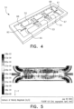
- FIG. 4 is a perspective view of the main body of a microfluidic beater of the system
- FIG. 5 is a prediction velocity and temperature plot along a thermal stage of the heater
- FIG. 6 is a centre line temperature profile in the flow direction showing fast response of same in the heated zone.
- FIG. 7 is a plan view of an alternative microfluidic heater.
- an analysis system 1 comprises a controller 2 which interfaces with various stages.
- a carrier fluid supply 4 delivers carrier fluid to a macro pump 5 which delivers it at a high flowrate to a sample preparation stage 6 .
- the latter also receives a bio-fluid sample, and centrifuges the sample in a vortex created by carrier fluid flow, as described in more detail below.
- Reactants are supplied by a supply 8 to a flow controller 7 which delivers streams of separated DNA with reactants enveloped in carrier fluid to a thermal cycling stage 9 .
- the DNA is amplified in the stage 9 and optically detected by a detection stage 10 .
- the samples are enveloped in a biologically non-reactive carrier fluid such as silicone oil. This avoids risk of contamination from residual molecules on system channel surfaces.
- a centrifuge device 20 of the sample preparation stage 6 is illustrated diagrammatically. It comprises opposed carrier supply lines 21 and 22 and a central vortex chamber 23 having a sample inlet out of the plane of the page.
- the centrifuge 20 operates by primary carrier fluid in the channels 21 and 22 driving sample fluid in the chamber 23 into a vortex via viscous forces at the interface between the two fluids.
- the carrier fluid is silicone oil mixed to be neutrally buoyant with the sample.
- FIG. 3 illustrates the centrifuging activity, the greater density of dots indicating higher flow velocities.
- the left-hand scale shows the velocity range of 1 m/s to 20 m/s.
- the sample is wrapped in an initial volume of carrier fluid within the chamber 23 to prevent surface contamination.
- the carrier fluid is pumped at speeds of 5 ms ⁇ 1 through the system.
- the desired carrier fluid speed is 1 m/s to 20 m/s.
- the device has further potential to be miniaturized to centrifuge at up to 200,000 g, as these levels of force are necessary for efficient separation of RNA and other smaller cellular constituents and bio-molecules.
- the continuous throughput centrifuge offers many benefits over conventional technology.
- the device may also function as a fluid mixing device by reversing the flow path of one of the carrier fluid, if such is desired for an application. It is modular in nature, meaning two or more systems can be placed together in any configuration and run by the same control and power source system.
- the centrifuge 20 has no moving parts thereby allowing excellent reliability compared with a system having moving pans. An important consequence of this feature is that manufacturing this device at the micro-scale using current silicon processing or micro-machining is readily achievable.
- a microfluidic thermal device 51 of the stage 9 is shown. It comprises three successive thermal zones 52 , 53 , and 54 . Each zone comprises a sample inlet 60 and an outlet 61 for flow of the bio sample in the primary carrier fluid. There are also a pair of thermal carrier inlets 65 and 66 , and a pair of thermal carrier outlets 67 and 68 for each of the three zones.
- This drawing shows only the main body, there also being top and bottom sealing transparent plates.
- the bio sample which enters the sample inlet 60 of each stage is enveloped and conveyed by the carrier fluid henceforth called the “primary carrier fluid”.
- Thermal carrier fluid is delivered at the inlets 65 and 66 to heat or cool the bio sample via the primary carrier fluid.
- the arrangement of a number (in this case three) of thermal zones in series offers advantages to applications such as the polymerase chain reaction (PCR) where rapid and numerous thermal cycles lead to dramatic amplification of a DNA template strand.
- PCR polymerase chain reaction
- the device 51 also acts as an ejector pump, in which the velocity and hence the residency time of the sample is controlled by controlling velocity of one or both of the carriers fluids.
- the carrier flow parameters determine how long the sample remains at the set temperature in each zone. This is often important, as chemical reactions require particular times for completion.
- the device 51 can therefore be tuned to the required residency times and ramp rates by controlling the carrier velocity.
- a predicted velocity contour map at the mid-height plane of a zone channel is shown.
- Carrier fluid enters through the channels at the top and bottom left of the image and exits through the channels at the top and bottom right of the image.
- the sample fluid enters and exits through the central channel.
- the different shadings of this map indicate the velocities, the range being 0.01 m/s to 0.1 m/s.
- sample fluid enters through the central channel at the left of the image at a temperature of 50° C. and is heated to 70° C. by the thermal carrier fluid.
- FIG. 6 shows a temperature profile along a longitudinal centerline of a thermal zone.
- a target temperature of 342 K is achieved within an extremely short distance from entrance, achieving an excellent temperature ramp rate of 20° C./sec over a distance of 0.05 m.
- a ramping of 17° C./sec to 25° C./sec is desirable for many applications.
- FIG. 7 another microfluidic thermal device, 70 , is shown.
- the zones 71 and 73 are on one side and there is only a single zone, 72 , on the other side.
- the thermal carrier fluid is silicone oil, as is the primary carrier fluid.
- the thermal carrier fluid for the zone 71 is at 68° C., to ramp up the bio sample to this temperature during residency in this zone.
- the zones 72 and 73 provide outlet temperatures of 95° C. and 72° C. respectively.
- the optical detection stage 10 is positioned over the microfluidic device 70 to analyze the sample.
- the silicone oil is sufficiently transparent to detect the fluorescently tagged molecules.
- the invention achieves comprehensive control over bio sample flowrate and temperature, with no risk of contamination from device surfaces.
- the invention also achieves integrated pumping and thermal cycling of the sample without moving parts at the microscale. There are very high throughputs as measured by processing time for one sample.
- the system is expected to have a low cost and high reliability due to the absence of micro scale moving parts.
- the system also allows independent control and variation of all PCR parameters for process optimization.
Abstract
Description
-
- a carrier fluid;
- a sample supply;
- a sample preparation stage for providing a flow of sample enveloped in a primary carrier fluid;
- at least one analysis stage for performing analysis of the sample while controlling flow of the sample while enveloped within the primary carrier fluid without the sample contacting a solid surface; and a controller for controlling the system.
| TABLE 2 |
| Boundary Conditions and Fluid Properties |
| Overall Channel Dimensions | 5 mm × 5 mm × 200 mm |
| Wall Boundary Condition outside of | Adiabatic |
| carrier flow interaction zones | |
| Heat Transfer |
70° C., 90° C., 110° C. |
| temperature | for each zone |
| Sample/Transfer |
0 Pa |
| Heat Transfer Carrier Fluid Inlet Pressure | 0.2 Pa |
| Sample/Transport Carrier Outlet Pressure | 1.9 Pa |
| Heat Transfer Carrier Fluid Outlet Pressure | 1.7 Pa |
| Mass Diffusivity | 1.3 E−12 m2/s |
| Approximate Temperature Gradient in | 20° C./sec |
| Zones | |
Claims (19)
Priority Applications (1)
| Application Number | Priority Date | Filing Date | Title |
|---|---|---|---|
| US16/892,488 US11807902B2 (en) | 2003-09-05 | 2020-06-04 | Microfluidic analysis system |
Applications Claiming Priority (7)
| Application Number | Priority Date | Filing Date | Title |
|---|---|---|---|
| US50034403P | 2003-09-05 | 2003-09-05 | |
| US50034503P | 2003-09-05 | 2003-09-05 | |
| PCT/IE2004/000115 WO2005023427A1 (en) | 2003-09-05 | 2004-09-06 | A microfluidic analysis system |
| US11/366,524 US7622076B2 (en) | 2003-09-05 | 2006-03-03 | Microfluidic analysis system |
| US12/617,286 US20100092987A1 (en) | 2003-09-05 | 2009-11-12 | Microfluidic analysis system |
| US15/278,894 US10676786B2 (en) | 2003-09-05 | 2016-09-28 | Microfluidic analysis system |
| US16/892,488 US11807902B2 (en) | 2003-09-05 | 2020-06-04 | Microfluidic analysis system |
Related Parent Applications (1)
| Application Number | Title | Priority Date | Filing Date |
|---|---|---|---|
| US15/278,894 Continuation US10676786B2 (en) | 2003-09-05 | 2016-09-28 | Microfluidic analysis system |
Publications (2)
| Publication Number | Publication Date |
|---|---|
| US20200354772A1 US20200354772A1 (en) | 2020-11-12 |
| US11807902B2 true US11807902B2 (en) | 2023-11-07 |
Family
ID=34278702
Family Applications (4)
| Application Number | Title | Priority Date | Filing Date |
|---|---|---|---|
| US11/366,524 Active 2026-06-01 US7622076B2 (en) | 2003-09-05 | 2006-03-03 | Microfluidic analysis system |
| US12/617,286 Abandoned US20100092987A1 (en) | 2003-09-05 | 2009-11-12 | Microfluidic analysis system |
| US15/278,894 Active 2025-09-21 US10676786B2 (en) | 2003-09-05 | 2016-09-28 | Microfluidic analysis system |
| US16/892,488 Active 2025-04-19 US11807902B2 (en) | 2003-09-05 | 2020-06-04 | Microfluidic analysis system |
Family Applications Before (3)
| Application Number | Title | Priority Date | Filing Date |
|---|---|---|---|
| US11/366,524 Active 2026-06-01 US7622076B2 (en) | 2003-09-05 | 2006-03-03 | Microfluidic analysis system |
| US12/617,286 Abandoned US20100092987A1 (en) | 2003-09-05 | 2009-11-12 | Microfluidic analysis system |
| US15/278,894 Active 2025-09-21 US10676786B2 (en) | 2003-09-05 | 2016-09-28 | Microfluidic analysis system |
Country Status (3)
| Country | Link |
|---|---|
| US (4) | US7622076B2 (en) |
| EP (1) | EP1663497B2 (en) |
| WO (1) | WO2005023427A1 (en) |
Families Citing this family (78)
| Publication number | Priority date | Publication date | Assignee | Title |
|---|---|---|---|---|
| US20100022414A1 (en) | 2008-07-18 | 2010-01-28 | Raindance Technologies, Inc. | Droplet Libraries |
| WO2005023427A1 (en) | 2003-09-05 | 2005-03-17 | Stokes Bio Limited | A microfluidic analysis system |
| US9597644B2 (en) * | 2003-09-05 | 2017-03-21 | Stokes Bio Limited | Methods for culturing and analyzing cells |
| US8968659B2 (en) | 2003-09-05 | 2015-03-03 | Stokes Bio Limited | Sample dispensing |
| US7968287B2 (en) | 2004-10-08 | 2011-06-28 | Medical Research Council Harvard University | In vitro evolution in microfluidic systems |
| WO2007081386A2 (en) | 2006-01-11 | 2007-07-19 | Raindance Technologies, Inc. | Microfluidic devices and methods of use |
| US8735169B2 (en) | 2006-02-07 | 2014-05-27 | Stokes Bio Limited | Methods for analyzing agricultural and environmental samples |
| US20100304446A1 (en) * | 2006-02-07 | 2010-12-02 | Stokes Bio Limited | Devices, systems, and methods for amplifying nucleic acids |
| WO2007091230A1 (en) * | 2006-02-07 | 2007-08-16 | Stokes Bio Limited | A microfluidic analysis system |
| US8501497B2 (en) | 2006-02-07 | 2013-08-06 | Stokes Bio Limited | Forming sample combinations using liquid bridge systems |
| ATE523244T1 (en) | 2006-02-07 | 2011-09-15 | Stokes Bio Ltd | LIQUID BRIDGE SYSTEM AND METHOD |
| US9562837B2 (en) | 2006-05-11 | 2017-02-07 | Raindance Technologies, Inc. | Systems for handling microfludic droplets |
| JP2010506136A (en) | 2006-05-11 | 2010-02-25 | レインダンス テクノロジーズ, インコーポレイテッド | Microfluidic device |
| WO2008038259A1 (en) * | 2006-09-28 | 2008-04-03 | Stokes Bio Limited | A qpcr analysis apparatus |
| WO2008097559A2 (en) | 2007-02-06 | 2008-08-14 | Brandeis University | Manipulation of fluids and reactions in microfluidic systems |
| BRPI0721509A2 (en) | 2007-03-26 | 2013-01-15 | Fundacion Gaiker | Method and device for detection of genetic material by polymerase chain reaction |
| US8592221B2 (en) | 2007-04-19 | 2013-11-26 | Brandeis University | Manipulation of fluids, fluid components and reactions in microfluidic systems |
| WO2010133965A2 (en) | 2009-05-19 | 2010-11-25 | Life Technologies Corporation | Sampling device |
| US9399797B2 (en) | 2010-02-12 | 2016-07-26 | Raindance Technologies, Inc. | Digital analyte analysis |
| US10351905B2 (en) | 2010-02-12 | 2019-07-16 | Bio-Rad Laboratories, Inc. | Digital analyte analysis |
| US9366632B2 (en) | 2010-02-12 | 2016-06-14 | Raindance Technologies, Inc. | Digital analyte analysis |
| EP3392349A1 (en) | 2010-02-12 | 2018-10-24 | Raindance Technologies, Inc. | Digital analyte analysis |
| EP3447155A1 (en) | 2010-09-30 | 2019-02-27 | Raindance Technologies, Inc. | Sandwich assays in droplets |
| EP3412778A1 (en) | 2011-02-11 | 2018-12-12 | Raindance Technologies, Inc. | Methods for forming mixed droplets |
| WO2012109604A1 (en) * | 2011-02-11 | 2012-08-16 | Raindance Technologies, Inc. | Thermocycling device for nucleic acid amplification and methods of use |
| WO2012112804A1 (en) | 2011-02-18 | 2012-08-23 | Raindance Technoligies, Inc. | Compositions and methods for molecular labeling |
| US20140120604A1 (en) | 2011-04-08 | 2014-05-01 | Stokes Bio Limited | Biological Detection System and Method of Use |
| WO2012139041A1 (en) | 2011-04-08 | 2012-10-11 | Stokes Bio Limited | System and method for charging fluids |
| EP3709018A1 (en) | 2011-06-02 | 2020-09-16 | Bio-Rad Laboratories, Inc. | Microfluidic apparatus for identifying components of a chemical reaction |
| US8658430B2 (en) | 2011-07-20 | 2014-02-25 | Raindance Technologies, Inc. | Manipulating droplet size |
| WO2013101743A2 (en) | 2011-12-30 | 2013-07-04 | Abbott Molecular, Inc. | Microorganism nucelic acid purification from host samples |
| US9701998B2 (en) | 2012-12-14 | 2017-07-11 | 10X Genomics, Inc. | Methods and systems for processing polynucleotides |
| CN114891871A (en) | 2012-08-14 | 2022-08-12 | 10X基因组学有限公司 | Microcapsule compositions and methods |
| US10584381B2 (en) | 2012-08-14 | 2020-03-10 | 10X Genomics, Inc. | Methods and systems for processing polynucleotides |
| US9388465B2 (en) | 2013-02-08 | 2016-07-12 | 10X Genomics, Inc. | Polynucleotide barcode generation |
| US10323279B2 (en) | 2012-08-14 | 2019-06-18 | 10X Genomics, Inc. | Methods and systems for processing polynucleotides |
| US11591637B2 (en) | 2012-08-14 | 2023-02-28 | 10X Genomics, Inc. | Compositions and methods for sample processing |
| US10533221B2 (en) | 2012-12-14 | 2020-01-14 | 10X Genomics, Inc. | Methods and systems for processing polynucleotides |
| US11901041B2 (en) | 2013-10-04 | 2024-02-13 | Bio-Rad Laboratories, Inc. | Digital analysis of nucleic acid modification |
| US9944977B2 (en) | 2013-12-12 | 2018-04-17 | Raindance Technologies, Inc. | Distinguishing rare variations in a nucleic acid sequence from a sample |
| US9824068B2 (en) | 2013-12-16 | 2017-11-21 | 10X Genomics, Inc. | Methods and apparatus for sorting data |
| CN113249435A (en) | 2014-06-26 | 2021-08-13 | 10X基因组学有限公司 | Methods of analyzing nucleic acids from individual cells or cell populations |
| AU2016207023B2 (en) | 2015-01-12 | 2019-12-05 | 10X Genomics, Inc. | Processes and systems for preparing nucleic acid sequencing libraries and libraries prepared using same |
| US10647981B1 (en) | 2015-09-08 | 2020-05-12 | Bio-Rad Laboratories, Inc. | Nucleic acid library generation methods and compositions |
| US11371094B2 (en) | 2015-11-19 | 2022-06-28 | 10X Genomics, Inc. | Systems and methods for nucleic acid processing using degenerate nucleotides |
| JP6735348B2 (en) | 2016-02-11 | 2020-08-05 | 10エックス ジェノミクス, インコーポレイテッド | Systems, methods and media for de novo assembly of whole genome sequence data |
| US10550429B2 (en) | 2016-12-22 | 2020-02-04 | 10X Genomics, Inc. | Methods and systems for processing polynucleotides |
| US10815525B2 (en) | 2016-12-22 | 2020-10-27 | 10X Genomics, Inc. | Methods and systems for processing polynucleotides |
| CN117512066A (en) | 2017-01-30 | 2024-02-06 | 10X基因组学有限公司 | Method and system for droplet-based single cell bar coding |
| US10995333B2 (en) | 2017-02-06 | 2021-05-04 | 10X Genomics, Inc. | Systems and methods for nucleic acid preparation |
| EP4215616A1 (en) | 2017-05-18 | 2023-07-26 | 10X Genomics, Inc. | Methods and systems for sorting droplets and beads |
| US10544413B2 (en) | 2017-05-18 | 2020-01-28 | 10X Genomics, Inc. | Methods and systems for sorting droplets and beads |
| US10357771B2 (en) | 2017-08-22 | 2019-07-23 | 10X Genomics, Inc. | Method of producing emulsions |
| US10837047B2 (en) | 2017-10-04 | 2020-11-17 | 10X Genomics, Inc. | Compositions, methods, and systems for bead formation using improved polymers |
| WO2019084043A1 (en) | 2017-10-26 | 2019-05-02 | 10X Genomics, Inc. | Methods and systems for nuclecic acid preparation and chromatin analysis |
| WO2019083852A1 (en) | 2017-10-26 | 2019-05-02 | 10X Genomics, Inc. | Microfluidic channel networks for partitioning |
| WO2019084165A1 (en) | 2017-10-27 | 2019-05-02 | 10X Genomics, Inc. | Methods and systems for sample preparation and analysis |
| SG11201913654QA (en) | 2017-11-15 | 2020-01-30 | 10X Genomics Inc | Functionalized gel beads |
| EP3717661A1 (en) | 2017-11-27 | 2020-10-07 | The Trustees of Columbia University in the City of New York | Rna printing and sequencing devices, methods, and systems |
| WO2019108851A1 (en) | 2017-11-30 | 2019-06-06 | 10X Genomics, Inc. | Systems and methods for nucleic acid preparation and analysis |
| CN112005115A (en) | 2018-02-12 | 2020-11-27 | 10X基因组学有限公司 | Methods of characterizing multiple analytes from a single cell or cell population |
| US11639928B2 (en) | 2018-02-22 | 2023-05-02 | 10X Genomics, Inc. | Methods and systems for characterizing analytes from individual cells or cell populations |
| EP3774005A4 (en) | 2018-04-02 | 2022-04-20 | Dropworks, Inc. | Systems and methods for serial flow emulsion processes |
| EP3775271A1 (en) | 2018-04-06 | 2021-02-17 | 10X Genomics, Inc. | Systems and methods for quality control in single cell processing |
| US11932899B2 (en) | 2018-06-07 | 2024-03-19 | 10X Genomics, Inc. | Methods and systems for characterizing nucleic acid molecules |
| US11703427B2 (en) | 2018-06-25 | 2023-07-18 | 10X Genomics, Inc. | Methods and systems for cell and bead processing |
| US20200032335A1 (en) | 2018-07-27 | 2020-01-30 | 10X Genomics, Inc. | Systems and methods for metabolome analysis |
| US11459607B1 (en) | 2018-12-10 | 2022-10-04 | 10X Genomics, Inc. | Systems and methods for processing-nucleic acid molecules from a single cell using sequential co-partitioning and composite barcodes |
| US11845983B1 (en) | 2019-01-09 | 2023-12-19 | 10X Genomics, Inc. | Methods and systems for multiplexing of droplet based assays |
| US11467153B2 (en) | 2019-02-12 | 2022-10-11 | 10X Genomics, Inc. | Methods for processing nucleic acid molecules |
| US11851683B1 (en) | 2019-02-12 | 2023-12-26 | 10X Genomics, Inc. | Methods and systems for selective analysis of cellular samples |
| SG11202108788TA (en) | 2019-02-12 | 2021-09-29 | 10X Genomics Inc | Methods for processing nucleic acid molecules |
| US11655499B1 (en) | 2019-02-25 | 2023-05-23 | 10X Genomics, Inc. | Detection of sequence elements in nucleic acid molecules |
| WO2020185791A1 (en) | 2019-03-11 | 2020-09-17 | 10X Genomics, Inc. | Systems and methods for processing optically tagged beads |
| WO2021201819A1 (en) * | 2020-03-30 | 2021-10-07 | Hewlett-Packard Development Company, L.P. | Intermittent warming of a biologic sample including a nucleic acid |
| US11851700B1 (en) | 2020-05-13 | 2023-12-26 | 10X Genomics, Inc. | Methods, kits, and compositions for processing extracellular molecules |
| EP4298244A1 (en) | 2021-02-23 | 2024-01-03 | 10X Genomics, Inc. | Probe-based analysis of nucleic acids and proteins |
| CN113607586A (en) * | 2021-07-19 | 2021-11-05 | 国网浙江省电力有限公司经济技术研究院 | Drop-wall flow separation test device |
Citations (72)
| Publication number | Priority date | Publication date | Assignee | Title |
|---|---|---|---|---|
| US4766082A (en) | 1984-10-24 | 1988-08-23 | Marteau D Autry Eric | Method and apparatus for preparing samples for analysis |
| US5102517A (en) | 1990-05-23 | 1992-04-07 | Millipore Corporation | Capillary wash system |
| US5270183A (en) | 1991-02-08 | 1993-12-14 | Beckman Research Institute Of The City Of Hope | Device and method for the automated cycling of solutions between two or more temperatures |
| US5720923A (en) | 1993-07-28 | 1998-02-24 | The Perkin-Elmer Corporation | Nucleic acid amplification reaction apparatus |
| WO1999041015A1 (en) | 1998-02-11 | 1999-08-19 | Institut für Physikalische Hochtechnologie e.V. | Miniaturized temperature-zone flow reactor |
| US6143496A (en) | 1997-04-17 | 2000-11-07 | Cytonix Corporation | Method of sampling, amplifying and quantifying segment of nucleic acid, polymerase chain reaction assembly having nanoliter-sized sample chambers, and method of filling assembly |
| WO2001001106A1 (en) | 1999-06-30 | 2001-01-04 | Perseptive Biosystems, Inc. | Pneumatic control of formation and transport of small volume liquid samples |
| US20010009757A1 (en) | 1990-09-13 | 2001-07-26 | Bischof Daniel F. | Apparatus for the separation of biologic components from heterogeneous cell populations |
| US6294063B1 (en) | 1999-02-12 | 2001-09-25 | Board Of Regents, The University Of Texas System | Method and apparatus for programmable fluidic processing |
| US6306590B1 (en) | 1998-06-08 | 2001-10-23 | Caliper Technologies Corp. | Microfluidic matrix localization apparatus and methods |
| WO2001089675A2 (en) | 2000-05-24 | 2001-11-29 | Micronics, Inc. | Jet vortex mixer |
| US20010048637A1 (en) | 2000-05-24 | 2001-12-06 | Weigl Bernhard H. | Microfluidic system and method |
| DE10055318A1 (en) | 2000-06-09 | 2001-12-20 | Advalytix Ag | Process for specific directed manipulation of small amounts of materials on solid body surfaces comprises producing an impulse along the solid body surface, and causing the impulse |
| US6355164B1 (en) | 1999-10-29 | 2002-03-12 | Ontogen Corporation | Sample collection apparatus and method for multiple channel high throughput purification |
| WO2002023163A1 (en) | 2000-09-15 | 2002-03-21 | California Institute Of Technology | Microfabricated crossflow devices and methods |
| WO2002040874A1 (en) | 2000-11-16 | 2002-05-23 | California Institute Of Technology | Apparatus and methods for conducting assays and high throughput screening |
| US20020060156A1 (en) | 1998-12-28 | 2002-05-23 | Affymetrix, Inc. | Integrated microvolume device |
| WO2002072264A1 (en) | 2001-03-09 | 2002-09-19 | Biomicro Systems, Inc. | Method and system for microfluidic interfacing to arrays |
| US20020166582A1 (en) | 2000-04-14 | 2002-11-14 | Nanostream, Inc. | Microfluidic branch metering systems and methods |
| US20020182749A1 (en) | 1999-05-11 | 2002-12-05 | Aclara Biosciences, Inc. | Sample evaporative control |
| WO2003016558A1 (en) | 2001-08-16 | 2003-02-27 | Corbett Research Pty Ltd | Continuous flow thermal device |
| US20030073089A1 (en) | 2001-10-16 | 2003-04-17 | Mauze Ganapati R. | Companion cartridge for disposable diagnostic sensing platforms |
| US20030080143A1 (en) | 2001-04-04 | 2003-05-01 | Arradial, Inc. | System and method for dispensing liquids |
| US6557427B2 (en) | 2000-05-24 | 2003-05-06 | Micronics, Inc. | Capillaries for fluid movement within microfluidic channels |
| WO2003057010A2 (en) | 2002-01-04 | 2003-07-17 | Board Of Regents, The University Of Texas System | Droplet-based microfluidic oligonucleotide synthesis engine |
| US20030138819A1 (en) | 2001-10-26 | 2003-07-24 | Haiqing Gong | Method for detecting disease |
| US20030182729A1 (en) | 2000-10-28 | 2003-10-02 | Williams David Mark | Body support arrangements |
| US20030201022A1 (en) | 2002-04-25 | 2003-10-30 | Tosoh Corporation | Fine channel device, fine particle producing method and solvent extraction method |
| US6670153B2 (en) | 2000-09-14 | 2003-12-30 | Caliper Technologies Corp. | Microfluidic devices and methods for performing temperature mediated reactions |
| US20040022686A1 (en) | 2002-05-07 | 2004-02-05 | Raymond Charles | Liquid product distribution device and method |
| WO2004038363A2 (en) | 2002-05-09 | 2004-05-06 | The University Of Chicago | Microfluidic device and method for pressure-driven plug transport and reaction |
| GB2395196A (en) | 2002-11-14 | 2004-05-19 | Univ Cardiff | Microfluidic device |
| US20040180346A1 (en) | 2003-03-14 | 2004-09-16 | The Regents Of The University Of California. | Chemical amplification based on fluid partitioning |
| US20040211659A1 (en) | 2003-01-13 | 2004-10-28 | Orlin Velev | Droplet transportation devices and methods having a fluid surface |
| WO2005002730A1 (en) | 2003-07-02 | 2005-01-13 | The University Of Manchester | Microfluidic method and device |
| US20050048581A1 (en) | 2003-08-25 | 2005-03-03 | Chiu Daniel T. | Method and device for biochemical detection and analysis of subcellular compartments from a single cell |
| WO2005023427A1 (en) | 2003-09-05 | 2005-03-17 | Stokes Bio Limited | A microfluidic analysis system |
| US20050092681A1 (en) | 2003-10-30 | 2005-05-05 | Konica Minolta Holdings, Inc. | Method, device and system for mixing liquids |
| US6907895B2 (en) | 2001-09-19 | 2005-06-21 | The United States Of America As Represented By The Secretary Of Commerce | Method for microfluidic flow manipulation |
| WO2005059512A2 (en) | 2003-12-10 | 2005-06-30 | Northeastern University | Method for efficient transport of small liquid volumes to, from or within microfluidic devices |
| WO2005080606A1 (en) | 2004-02-18 | 2005-09-01 | Xiaochuan Zhou | Fluidic devices and methods for multiplex chemical and biochemical reactions |
| EP1574586A2 (en) | 2004-03-12 | 2005-09-14 | Samsung Electronics Co., Ltd. | Method and apparatus for amplifying nucleic acids |
| US20050221339A1 (en) | 2004-03-31 | 2005-10-06 | Medical Research Council Harvard University | Compartmentalised screening by microfluidic control |
| US20050272144A1 (en) | 2004-06-08 | 2005-12-08 | Konica Minolta Medical & Graphic, Inc. | Micro-reactor for improving efficiency of liquid mixing and reaction |
| US20060094119A1 (en) | 2004-10-29 | 2006-05-04 | Ismagilov Rustem F | Microfluidic system |
| US7056660B1 (en) * | 1997-08-22 | 2006-06-06 | Michael Giesing | Method for characterizing disseminated and micrometastasized cancer cells |
| US7077152B2 (en) | 2001-07-07 | 2006-07-18 | Nanostream, Inc. | Microfluidic metering systems and methods |
| US20060257893A1 (en) | 2005-02-18 | 2006-11-16 | Toru Takahashi | Devices and methods for monitoring genomic DNA of organisms |
| US20070014695A1 (en) | 2005-04-26 | 2007-01-18 | Applera Corporation | Systems and Methods for Multiple Analyte Detection |
| US20070039866A1 (en) | 2005-08-22 | 2007-02-22 | Schroeder Benjamin G | Device, system, and method for depositing processed immiscible-fluid-discrete-volumes |
| US7189580B2 (en) | 2001-10-19 | 2007-03-13 | Wisconsin Alumni Research Foundation | Method of pumping fluid through a microfluidic device |
| US20070134209A1 (en) | 2005-12-12 | 2007-06-14 | Metafluidics, Inc. | Cellular encapsulation for self-assembly of engineered tissue |
| US7238268B2 (en) | 1999-08-12 | 2007-07-03 | Ut-Battelle, Llc | Microfluidic devices for the controlled manipulation of small volumes |
| WO2007091229A1 (en) | 2006-02-07 | 2007-08-16 | Stokes Bio Limited | A microfluidic droplet queuing network |
| WO2007091228A1 (en) | 2006-02-07 | 2007-08-16 | Stokes Bio Limited | A liquid bridge and system |
| WO2007091230A1 (en) | 2006-02-07 | 2007-08-16 | Stokes Bio Limited | A microfluidic analysis system |
| WO2007133710A2 (en) | 2006-05-11 | 2007-11-22 | Raindance Technologies, Inc. | Microfluidic devices and methods of use thereof |
| US20070275415A1 (en) | 2006-04-18 | 2007-11-29 | Vijay Srinivasan | Droplet-based affinity assays |
| WO2008038259A1 (en) | 2006-09-28 | 2008-04-03 | Stokes Bio Limited | A qpcr analysis apparatus |
| US20100022414A1 (en) | 2008-07-18 | 2010-01-28 | Raindance Technologies, Inc. | Droplet Libraries |
| US20100041086A1 (en) | 2007-03-22 | 2010-02-18 | Advanced Liquid Logic, Inc. | Enzyme Assays for a Droplet Actuator |
| US20100059120A1 (en) | 2008-09-11 | 2010-03-11 | General Electric Company | Microfluidic device and methods for droplet generation and manipulation |
| US20100216128A1 (en) | 2006-02-07 | 2010-08-26 | Stokes Bio Ltd. | Methods for analyzing agricultural and environmental samples |
| WO2010133963A2 (en) | 2009-05-20 | 2010-11-25 | Life Technologies Corporation | Forming sample combinations using liquid bridge systems |
| US20100297685A1 (en) | 2003-09-05 | 2010-11-25 | Stokes Bio Limited | Methods for culturing and analyzing cells |
| US20110059556A1 (en) | 2009-09-04 | 2011-03-10 | The Research Foundation Of State University Of New York | Rapid and Continuous Analyte Processing in Droplet Microfluidic Devices |
| US8304193B2 (en) | 2002-05-09 | 2012-11-06 | The University Of Chicago | Method for conducting an autocatalytic reaction in plugs in a microfluidic system |
| US8592221B2 (en) | 2007-04-19 | 2013-11-26 | Brandeis University | Manipulation of fluids, fluid components and reactions in microfluidic systems |
| US8697011B2 (en) | 2009-05-19 | 2014-04-15 | Stokes Bio Limited | Sampling device with immiscible fluid supply tube in counter-flow arrangement |
| US8968659B2 (en) | 2003-09-05 | 2015-03-03 | Stokes Bio Limited | Sample dispensing |
| US9127310B2 (en) | 2010-02-12 | 2015-09-08 | Raindance Technologies, Inc. | Digital analyte analysis |
| EP3299469A1 (en) | 2014-04-21 | 2018-03-28 | President and Fellows of Harvard College | Systems and methods for barcoding nucleic acid |
-
2004
- 2004-09-06 WO PCT/IE2004/000115 patent/WO2005023427A1/en active Application Filing
- 2004-09-06 EP EP04770390.5A patent/EP1663497B2/en active Active
-
2006
- 2006-03-03 US US11/366,524 patent/US7622076B2/en active Active
-
2009
- 2009-11-12 US US12/617,286 patent/US20100092987A1/en not_active Abandoned
-
2016
- 2016-09-28 US US15/278,894 patent/US10676786B2/en active Active
-
2020
- 2020-06-04 US US16/892,488 patent/US11807902B2/en active Active
Patent Citations (116)
| Publication number | Priority date | Publication date | Assignee | Title |
|---|---|---|---|---|
| US4766082A (en) | 1984-10-24 | 1988-08-23 | Marteau D Autry Eric | Method and apparatus for preparing samples for analysis |
| US5102517A (en) | 1990-05-23 | 1992-04-07 | Millipore Corporation | Capillary wash system |
| US20010009757A1 (en) | 1990-09-13 | 2001-07-26 | Bischof Daniel F. | Apparatus for the separation of biologic components from heterogeneous cell populations |
| US5270183A (en) | 1991-02-08 | 1993-12-14 | Beckman Research Institute Of The City Of Hope | Device and method for the automated cycling of solutions between two or more temperatures |
| US5720923A (en) | 1993-07-28 | 1998-02-24 | The Perkin-Elmer Corporation | Nucleic acid amplification reaction apparatus |
| US5779977A (en) | 1993-07-28 | 1998-07-14 | The Perkin-Elmer Corporation | Nucleic acid amplification reaction apparatus and method |
| US5827480A (en) | 1993-07-28 | 1998-10-27 | The Perkin-Elmer Corporation | Nucleic acid amplification reaction apparatus |
| US6033880A (en) | 1993-07-28 | 2000-03-07 | The Perkin-Elmer Corporation | Nucleic acid amplification reaction apparatus and method |
| US20040171055A1 (en) | 1997-04-17 | 2004-09-02 | Cytonix Corporation | Method for detecting the presence of a single target nucleic acid in a sample |
| US6143496A (en) | 1997-04-17 | 2000-11-07 | Cytonix Corporation | Method of sampling, amplifying and quantifying segment of nucleic acid, polymerase chain reaction assembly having nanoliter-sized sample chambers, and method of filling assembly |
| US7459315B2 (en) | 1997-04-17 | 2008-12-02 | Cytonix Corporation | Miniaturized assembly and method of filling assembly |
| US7056660B1 (en) * | 1997-08-22 | 2006-06-06 | Michael Giesing | Method for characterizing disseminated and micrometastasized cancer cells |
| WO1999041015A1 (en) | 1998-02-11 | 1999-08-19 | Institut für Physikalische Hochtechnologie e.V. | Miniaturized temperature-zone flow reactor |
| US6306590B1 (en) | 1998-06-08 | 2001-10-23 | Caliper Technologies Corp. | Microfluidic matrix localization apparatus and methods |
| US20020060156A1 (en) | 1998-12-28 | 2002-05-23 | Affymetrix, Inc. | Integrated microvolume device |
| US6294063B1 (en) | 1999-02-12 | 2001-09-25 | Board Of Regents, The University Of Texas System | Method and apparatus for programmable fluidic processing |
| US20020182749A1 (en) | 1999-05-11 | 2002-12-05 | Aclara Biosciences, Inc. | Sample evaporative control |
| WO2001001106A1 (en) | 1999-06-30 | 2001-01-04 | Perseptive Biosystems, Inc. | Pneumatic control of formation and transport of small volume liquid samples |
| US6193471B1 (en) | 1999-06-30 | 2001-02-27 | Perseptive Biosystems, Inc. | Pneumatic control of formation and transport of small volume liquid samples |
| US7238268B2 (en) | 1999-08-12 | 2007-07-03 | Ut-Battelle, Llc | Microfluidic devices for the controlled manipulation of small volumes |
| US6355164B1 (en) | 1999-10-29 | 2002-03-12 | Ontogen Corporation | Sample collection apparatus and method for multiple channel high throughput purification |
| US20020166582A1 (en) | 2000-04-14 | 2002-11-14 | Nanostream, Inc. | Microfluidic branch metering systems and methods |
| US6557427B2 (en) | 2000-05-24 | 2003-05-06 | Micronics, Inc. | Capillaries for fluid movement within microfluidic channels |
| US20010048637A1 (en) | 2000-05-24 | 2001-12-06 | Weigl Bernhard H. | Microfluidic system and method |
| WO2001089675A2 (en) | 2000-05-24 | 2001-11-29 | Micronics, Inc. | Jet vortex mixer |
| DE10055318A1 (en) | 2000-06-09 | 2001-12-20 | Advalytix Ag | Process for specific directed manipulation of small amounts of materials on solid body surfaces comprises producing an impulse along the solid body surface, and causing the impulse |
| US6670153B2 (en) | 2000-09-14 | 2003-12-30 | Caliper Technologies Corp. | Microfluidic devices and methods for performing temperature mediated reactions |
| WO2002023163A1 (en) | 2000-09-15 | 2002-03-21 | California Institute Of Technology | Microfabricated crossflow devices and methods |
| US7294503B2 (en) | 2000-09-15 | 2007-11-13 | California Institute Of Technology | Microfabricated crossflow devices and methods |
| US20030182729A1 (en) | 2000-10-28 | 2003-10-02 | Williams David Mark | Body support arrangements |
| WO2002040874A1 (en) | 2000-11-16 | 2002-05-23 | California Institute Of Technology | Apparatus and methods for conducting assays and high throughput screening |
| WO2002072264A1 (en) | 2001-03-09 | 2002-09-19 | Biomicro Systems, Inc. | Method and system for microfluidic interfacing to arrays |
| US20030080143A1 (en) | 2001-04-04 | 2003-05-01 | Arradial, Inc. | System and method for dispensing liquids |
| US7077152B2 (en) | 2001-07-07 | 2006-07-18 | Nanostream, Inc. | Microfluidic metering systems and methods |
| WO2003016558A1 (en) | 2001-08-16 | 2003-02-27 | Corbett Research Pty Ltd | Continuous flow thermal device |
| US6907895B2 (en) | 2001-09-19 | 2005-06-21 | The United States Of America As Represented By The Secretary Of Commerce | Method for microfluidic flow manipulation |
| US20030073089A1 (en) | 2001-10-16 | 2003-04-17 | Mauze Ganapati R. | Companion cartridge for disposable diagnostic sensing platforms |
| US7189580B2 (en) | 2001-10-19 | 2007-03-13 | Wisconsin Alumni Research Foundation | Method of pumping fluid through a microfluidic device |
| US20030138819A1 (en) | 2001-10-26 | 2003-07-24 | Haiqing Gong | Method for detecting disease |
| WO2003057010A2 (en) | 2002-01-04 | 2003-07-17 | Board Of Regents, The University Of Texas System | Droplet-based microfluidic oligonucleotide synthesis engine |
| US20030170698A1 (en) | 2002-01-04 | 2003-09-11 | Peter Gascoyne | Droplet-based microfluidic oligonucleotide synthesis engine |
| US20030201022A1 (en) | 2002-04-25 | 2003-10-30 | Tosoh Corporation | Fine channel device, fine particle producing method and solvent extraction method |
| US7235405B2 (en) | 2002-05-07 | 2007-06-26 | Commissariat A L'energie Atomique | Liquid product distribution device and method |
| US20040022686A1 (en) | 2002-05-07 | 2004-02-05 | Raymond Charles | Liquid product distribution device and method |
| EP1361442B1 (en) | 2002-05-07 | 2006-07-19 | Commissariat A L'energie Atomique | method and device for dispensing liquids |
| US20050272159A1 (en) | 2002-05-09 | 2005-12-08 | Ismagilov Rustem F | Device and method for pressure-driven plug transport and reaction |
| US8329407B2 (en) | 2002-05-09 | 2012-12-11 | The University Of Chicago | Method for conducting reactions involving biological molecules in plugs in a microfluidic system |
| US8822148B2 (en) | 2002-05-09 | 2014-09-02 | The University Of Chicago | Method of performing PCR reaction in continuously flowing microfluidic plugs |
| EP1508044B1 (en) | 2002-05-09 | 2010-09-01 | The University of Chicago | Device and method for pressure-driven plug transport and reaction |
| WO2004038363A2 (en) | 2002-05-09 | 2004-05-06 | The University Of Chicago | Microfluidic device and method for pressure-driven plug transport and reaction |
| US8304193B2 (en) | 2002-05-09 | 2012-11-06 | The University Of Chicago | Method for conducting an autocatalytic reaction in plugs in a microfluidic system |
| US7129091B2 (en) | 2002-05-09 | 2006-10-31 | University Of Chicago | Device and method for pressure-driven plug transport and reaction |
| US8889083B2 (en) | 2002-05-09 | 2014-11-18 | The University Of Chicago | Device and method for pressure-driven plug transport and reaction |
| GB2395196A (en) | 2002-11-14 | 2004-05-19 | Univ Cardiff | Microfluidic device |
| US20040211659A1 (en) | 2003-01-13 | 2004-10-28 | Orlin Velev | Droplet transportation devices and methods having a fluid surface |
| USRE41780E1 (en) | 2003-03-14 | 2010-09-28 | Lawrence Livermore National Security, Llc | Chemical amplification based on fluid partitioning in an immiscible liquid |
| US20040180346A1 (en) | 2003-03-14 | 2004-09-16 | The Regents Of The University Of California. | Chemical amplification based on fluid partitioning |
| US7041481B2 (en) | 2003-03-14 | 2006-05-09 | The Regents Of The University Of California | Chemical amplification based on fluid partitioning |
| USRE43365E1 (en) | 2003-03-14 | 2012-05-08 | Lawrence Livermore National Security, Llc | Apparatus for chemical amplification based on fluid partitioning in an immiscible liquid |
| WO2005002730A1 (en) | 2003-07-02 | 2005-01-13 | The University Of Manchester | Microfluidic method and device |
| US20050048581A1 (en) | 2003-08-25 | 2005-03-03 | Chiu Daniel T. | Method and device for biochemical detection and analysis of subcellular compartments from a single cell |
| US20100297685A1 (en) | 2003-09-05 | 2010-11-25 | Stokes Bio Limited | Methods for culturing and analyzing cells |
| WO2005023427A1 (en) | 2003-09-05 | 2005-03-17 | Stokes Bio Limited | A microfluidic analysis system |
| US7622076B2 (en) | 2003-09-05 | 2009-11-24 | Stokes Bio Limited | Microfluidic analysis system |
| US20100092987A1 (en) | 2003-09-05 | 2010-04-15 | Stokes Bio Limited | Microfluidic analysis system |
| US8968659B2 (en) | 2003-09-05 | 2015-03-03 | Stokes Bio Limited | Sample dispensing |
| US10676786B2 (en) | 2003-09-05 | 2020-06-09 | Stokes Bio Ltd. | Microfluidic analysis system |
| US20050092681A1 (en) | 2003-10-30 | 2005-05-05 | Konica Minolta Holdings, Inc. | Method, device and system for mixing liquids |
| WO2005059512A2 (en) | 2003-12-10 | 2005-06-30 | Northeastern University | Method for efficient transport of small liquid volumes to, from or within microfluidic devices |
| US20070117212A1 (en) | 2003-12-10 | 2007-05-24 | Kautz Roger A | Method for efficient transport of small liquid volumes to, from or within microfluidic devices |
| WO2005080606A1 (en) | 2004-02-18 | 2005-09-01 | Xiaochuan Zhou | Fluidic devices and methods for multiplex chemical and biochemical reactions |
| EP1574586A2 (en) | 2004-03-12 | 2005-09-14 | Samsung Electronics Co., Ltd. | Method and apparatus for amplifying nucleic acids |
| US20050202489A1 (en) | 2004-03-12 | 2005-09-15 | Cho Yoon-Kyoung | Method and apparatus for amplifying nucleic acids |
| US20050221339A1 (en) | 2004-03-31 | 2005-10-06 | Medical Research Council Harvard University | Compartmentalised screening by microfluidic control |
| US20050272144A1 (en) | 2004-06-08 | 2005-12-08 | Konica Minolta Medical & Graphic, Inc. | Micro-reactor for improving efficiency of liquid mixing and reaction |
| US20060094119A1 (en) | 2004-10-29 | 2006-05-04 | Ismagilov Rustem F | Microfluidic system |
| US20060257893A1 (en) | 2005-02-18 | 2006-11-16 | Toru Takahashi | Devices and methods for monitoring genomic DNA of organisms |
| US7604938B2 (en) | 2005-02-18 | 2009-10-20 | Canon U.S. Life Sciences, Inc. | Devices and methods for monitoring genomic DNA of organisms |
| US20070014695A1 (en) | 2005-04-26 | 2007-01-18 | Applera Corporation | Systems and Methods for Multiple Analyte Detection |
| US20070062583A1 (en) | 2005-08-22 | 2007-03-22 | Cox David M | Device and method for making discrete volumes of a first fluid in contact with a second fluid, which are immiscible with each other |
| US20070039866A1 (en) | 2005-08-22 | 2007-02-22 | Schroeder Benjamin G | Device, system, and method for depositing processed immiscible-fluid-discrete-volumes |
| US20070068573A1 (en) | 2005-08-22 | 2007-03-29 | Applera Corporation | Device and method for microfluidic control of a first fluid in contact with a second fluid, wherein the first and second fluids are immiscible |
| US20070141593A1 (en) | 2005-08-22 | 2007-06-21 | Lee Linda G | Apparatus, system, and method using immiscible-fluid-discrete-volumes |
| US20070134209A1 (en) | 2005-12-12 | 2007-06-14 | Metafluidics, Inc. | Cellular encapsulation for self-assembly of engineered tissue |
| WO2007091228A1 (en) | 2006-02-07 | 2007-08-16 | Stokes Bio Limited | A liquid bridge and system |
| US8501497B2 (en) | 2006-02-07 | 2013-08-06 | Stokes Bio Limited | Forming sample combinations using liquid bridge systems |
| EP1981625B1 (en) | 2006-02-07 | 2010-08-18 | Stokes Bio Limited | A microfluidic droplet queuing network and method |
| WO2007091229A1 (en) | 2006-02-07 | 2007-08-16 | Stokes Bio Limited | A microfluidic droplet queuing network |
| US20160339435A1 (en) | 2006-02-07 | 2016-11-24 | Stokes Bio Limited | Liquid Bridge and System |
| US20150352513A1 (en) | 2006-02-07 | 2015-12-10 | Stokes Bio Limited | Microfluidic Droplet Queuing Network |
| US9108177B2 (en) | 2006-02-07 | 2015-08-18 | Stokes Bio Limited | Microfluidic droplet queuing network |
| WO2007091230A1 (en) | 2006-02-07 | 2007-08-16 | Stokes Bio Limited | A microfluidic analysis system |
| EP2298438A1 (en) | 2006-02-07 | 2011-03-23 | Stokes Bio Limited | A microfluidic droplet queuing network |
| US7993911B2 (en) | 2006-02-07 | 2011-08-09 | Stokes Bio Limited | Microfluidic droplet queuing network |
| EP1981624B1 (en) | 2006-02-07 | 2011-09-07 | Stokes Bio Limited | A liquid bridge system and method |
| US8735169B2 (en) | 2006-02-07 | 2014-05-27 | Stokes Bio Limited | Methods for analyzing agricultural and environmental samples |
| US8298833B2 (en) | 2006-02-07 | 2012-10-30 | Stokes Bio Limited | Liquid bridge and system |
| US20080277494A1 (en) | 2006-02-07 | 2008-11-13 | Stokes Bio Limited | Liquid Bridge and System |
| US8563244B2 (en) | 2006-02-07 | 2013-10-22 | Stokes Bio Limited | Microfluidic droplet queuing network |
| US20100216128A1 (en) | 2006-02-07 | 2010-08-26 | Stokes Bio Ltd. | Methods for analyzing agricultural and environmental samples |
| US20170320025A1 (en) | 2006-03-03 | 2017-11-09 | Stokes Bio Limited | Methods for culturing and analyzing cells |
| US20070275415A1 (en) | 2006-04-18 | 2007-11-29 | Vijay Srinivasan | Droplet-based affinity assays |
| WO2007133710A2 (en) | 2006-05-11 | 2007-11-22 | Raindance Technologies, Inc. | Microfluidic devices and methods of use thereof |
| WO2008038259A1 (en) | 2006-09-28 | 2008-04-03 | Stokes Bio Limited | A qpcr analysis apparatus |
| US20100041086A1 (en) | 2007-03-22 | 2010-02-18 | Advanced Liquid Logic, Inc. | Enzyme Assays for a Droplet Actuator |
| US8592221B2 (en) | 2007-04-19 | 2013-11-26 | Brandeis University | Manipulation of fluids, fluid components and reactions in microfluidic systems |
| US10286396B2 (en) | 2007-04-19 | 2019-05-14 | Brandeis University | Manipulation of fluids, fluid components and reactions in microfluidic systems |
| US20100022414A1 (en) | 2008-07-18 | 2010-01-28 | Raindance Technologies, Inc. | Droplet Libraries |
| US20100059120A1 (en) | 2008-09-11 | 2010-03-11 | General Electric Company | Microfluidic device and methods for droplet generation and manipulation |
| US8697011B2 (en) | 2009-05-19 | 2014-04-15 | Stokes Bio Limited | Sampling device with immiscible fluid supply tube in counter-flow arrangement |
| WO2010133963A2 (en) | 2009-05-20 | 2010-11-25 | Life Technologies Corporation | Forming sample combinations using liquid bridge systems |
| WO2010133962A1 (en) | 2009-05-20 | 2010-11-25 | Life Technologies Corporation | Methods for analyzing agricultural and environmental samples using microfluidic systems |
| US20110059556A1 (en) | 2009-09-04 | 2011-03-10 | The Research Foundation Of State University Of New York | Rapid and Continuous Analyte Processing in Droplet Microfluidic Devices |
| US9441266B2 (en) | 2010-02-12 | 2016-09-13 | Raindance Technologies, Inc. | Digital analyte analysis |
| US9127310B2 (en) | 2010-02-12 | 2015-09-08 | Raindance Technologies, Inc. | Digital analyte analysis |
| EP3299469A1 (en) | 2014-04-21 | 2018-03-28 | President and Fellows of Harvard College | Systems and methods for barcoding nucleic acid |
Non-Patent Citations (24)
| Title |
|---|
| 04770390.5, Office Action dated Apr. 28, 2011, 3 pgs. |
| Bernard, "Real-time PCR technology for cancer diagnostics", Clinical Chemistry 48(8) 2002, 1178-85. |
| Brouzes, Eric et al., "Droplet Microfluidic Technology for Single-Cell High-throughput Screening", Proceedings of the National Academy of Sciences, vol. 106, No. 34, 2009, 14195-14200. |
| Curran, K.; Colin, S.; Baidas, L. "Liquid bridge instability applied to microfluidics", Microfluid Nanfluid, 2005, pp. 336-345. |
| EPC Communication for Application No. 10 749 681.2, dated May 17, 2016. |
| Extended Search Report (EP Form 1703) from EP Appl. No. 15 187 064.9, dated Dec. 4, 2015. |
| Fang J.; Huang Y.; Wang X.-B.; Becker, F.F.; Gascoyne, R.C. "Cell Separation on Microfabricated Electrodes Using Dielectrophoretic/Gravitational Field-Flow Fractionation" Anal. Chem 1999, 71, pp. 91-918. |
| FluoroMed Trade Name: APF-215M, (online), http://fluoromed.com/products/perfluoroperhydrophenanthrene.html, retrieved May 17, 2011. |
| Geun Chung, B.; Flanagan, L.A.; Rhee, S.W.; Schwartz, P.H.; Monuki, E.S.; Jeon, N.L., "Human neural stem cell growth and differentiation in a gradient-generating microfludic device", Lab on a Chip, 2005, 5, pp. 401-406. |
| He, M.; Edgar, J.S.; Jeffries, G.D.M.; Lorenz, R.M.; Shelby, J.P.; Chiu, D.T. "Selective Encapsulation of Single Cells and Subcellular Organelles into Picoliter and Femtoliter-Volume Droplets", Anal Chem. 2005, 77, pp. 1539-1544. |
| International Preliminary Report on Patentability for PCT/IE2007/000013 dated May 11, 2007. |
| International Preliminary Report on Patentability for PCT/US2011/030034, dated Oct. 2, 2012. |
| International Search Report for Application No. PCT/IB10/01233 dated Oct. 22, 2010. |
| International Search Report for Application No. PCT/IB2010/001254 dated Oct. 28, 2010. |
| International Search Report for PCT/IE2007/000013, dated May 11, 2007. |
| Kumaresan, P.; Yang, C.J.; Cronier, S.A.; Blazej, R.G.; Mathies, R.A.; "High-Throughput Single Copy DNA Amplification and Cell Analysis in Engineered Nanoliter Droplets", Anal. Chem., 2008, 80, pp. 3522-3529. |
| Medkova, Martina et al, "Analyzing Cancer at Single Cell Resolution with Droplet Technology", American Association of Cancer Research, RainDance Technologies, Apr. 19, 2010. |
| Meriam-Webster.com definition of "segment", obtained on Jul. 7, 2015, pp. 1-4. |
| Miyamura et al. Detection of Philadelphia Chromosome—Positive Acute Lymphoblastic Leukemia by Polymerase Chain Reaction: Possible Eradication of Minimal Residual Disease by Marrow Transplantation. Blood 79(5):1366-1370. (Year: 1992). * |
| Nakano, H. et al., "High Speed Polymerase Chain Reaction in Constant Flow", Biosci. Biotech. Biochem, vol. 58 (2), Jun. 12, 2014, 349-352. |
| Nakano, M.; Komatsu, J.; Matsuura, S.; Takashima, K.; Katsure, S.; Mizuno, A. "Single-Molecule PCR using water-in-oil emulstion", Journal of Biotechnology, 2003, 102, pp. 117-124. |
| Newport, D.; Davies, M.; Dalton, T. "Microfluidics for Genetic Caner Diagnostics", La Houille Blanche, Jan.-Feb. 2006, 1, pp. 26-33. |
| Thouas, G.A.; Jones, G.M.; Trounson, A.O. "The ‘GO’ system—a novel method of microculture for in vitro development of mouse zygotes to the blastocyst strage", Reproduction, 2003, 126, pp. 161-169. |
| Written Opinion for Application No. PCT/IE2007/00013, dated May 14, 2008. |
Also Published As
| Publication number | Publication date |
|---|---|
| US7622076B2 (en) | 2009-11-24 |
| US20060205062A1 (en) | 2006-09-14 |
| US20100092987A1 (en) | 2010-04-15 |
| WO2005023427A1 (en) | 2005-03-17 |
| US10676786B2 (en) | 2020-06-09 |
| EP1663497B1 (en) | 2014-08-27 |
| EP1663497B2 (en) | 2020-03-25 |
| US20170081705A1 (en) | 2017-03-23 |
| EP1663497A1 (en) | 2006-06-07 |
| US20200354772A1 (en) | 2020-11-12 |
Similar Documents
| Publication | Publication Date | Title |
|---|---|---|
| US11807902B2 (en) | Microfluidic analysis system | |
| Yuen et al. | Microchip module for blood sample preparation and nucleic acid amplification reactions | |
| US10239057B2 (en) | Microfluidic devices and methods for cell analysis and molecular diagnostics | |
| US10543466B2 (en) | High resolution temperature profile creation in a digital microfluidic device | |
| US10232371B2 (en) | Microfluidic devices and methods for cell processing | |
| EP0637999B1 (en) | Polynucleotide amplification analysis using a microfabricated device | |
| US6896855B1 (en) | Miniaturized temperature-zone flow reactor | |
| WO2004073863A2 (en) | Chemical reactions apparatus | |
| EP2846911B1 (en) | Plurality of reaction chambers in a test cartridge | |
| US20120045765A1 (en) | Composite liquid cells | |
| US20120040404A1 (en) | Thermal cycling device | |
| US11814671B2 (en) | System and method for leakage control in a particle capture system | |
| Lien et al. | Miniaturization of molecular biological techniques for gene assay | |
| WO2005082535A1 (en) | Buoyancy-driven microfluidics | |
| US9616423B2 (en) | Microreactor with vent channels for removing air from a reaction chamber | |
| KR102043103B1 (en) | Automatic genetic detector | |
| IE20040589A1 (en) | A microfluidic analysis system | |
| IE84099B1 (en) | A microfluidic analysis system | |
| US20230008992A1 (en) | Devices for generating pre-templated instant partitions | |
| Brahmasandra et al. | A microfabricated fluidic reaction and separation system for integrated DNA analysis | |
| CN116083223A (en) | Nucleic acid detection equipment and system | |
| US20220080413A1 (en) | Disposable microfluidic cassettes | |
| IE20050100A1 (en) | Microfluidics | |
| US20160375441A1 (en) | Apparatus and method for nucleic acid amplification | |
| Mohr et al. | Optimal design and operation for a droplet-based PCR chip |
Legal Events
| Date | Code | Title | Description |
|---|---|---|---|
| FEPP | Fee payment procedure |
Free format text: ENTITY STATUS SET TO UNDISCOUNTED (ORIGINAL EVENT CODE: BIG.); ENTITY STATUS OF PATENT OWNER: LARGE ENTITY |
|
| AS | Assignment |
Owner name: STOKES BIO LTD., IRELAND Free format text: ASSIGNMENT OF ASSIGNORS INTEREST;ASSIGNORS:DAVIES, MARK;DALTON, TARA;REEL/FRAME:052852/0013 Effective date: 20090812 |
|
| STPP | Information on status: patent application and granting procedure in general |
Free format text: DOCKETED NEW CASE - READY FOR EXAMINATION |
|
| STPP | Information on status: patent application and granting procedure in general |
Free format text: NON FINAL ACTION MAILED |
|
| STPP | Information on status: patent application and granting procedure in general |
Free format text: RESPONSE TO NON-FINAL OFFICE ACTION ENTERED AND FORWARDED TO EXAMINER |
|
| STPP | Information on status: patent application and granting procedure in general |
Free format text: FINAL REJECTION MAILED |
|
| STPP | Information on status: patent application and granting procedure in general |
Free format text: DOCKETED NEW CASE - READY FOR EXAMINATION |
|
| STPP | Information on status: patent application and granting procedure in general |
Free format text: NOTICE OF ALLOWANCE MAILED -- APPLICATION RECEIVED IN OFFICE OF PUBLICATIONS |
|
| STPP | Information on status: patent application and granting procedure in general |
Free format text: PUBLICATIONS -- ISSUE FEE PAYMENT VERIFIED |
|
| STCF | Information on status: patent grant |
Free format text: PATENTED CASE |