US11795009B2 - Method for merging, within a logistical warehouse, k incoming flows of payloads into one outgoing flow - Google Patents
Method for merging, within a logistical warehouse, k incoming flows of payloads into one outgoing flow Download PDFInfo
- Publication number
- US11795009B2 US11795009B2 US17/083,887 US202017083887A US11795009B2 US 11795009 B2 US11795009 B2 US 11795009B2 US 202017083887 A US202017083887 A US 202017083887A US 11795009 B2 US11795009 B2 US 11795009B2
- Authority
- US
- United States
- Prior art keywords
- collector
- lane
- injection
- last
- load
- Prior art date
- Legal status (The legal status is an assumption and is not a legal conclusion. Google has not performed a legal analysis and makes no representation as to the accuracy of the status listed.)
- Active, expires
Links
Images




Classifications
-
- G—PHYSICS
- G06—COMPUTING OR CALCULATING; COUNTING
- G06Q—INFORMATION AND COMMUNICATION TECHNOLOGY [ICT] SPECIALLY ADAPTED FOR ADMINISTRATIVE, COMMERCIAL, FINANCIAL, MANAGERIAL OR SUPERVISORY PURPOSES; SYSTEMS OR METHODS SPECIALLY ADAPTED FOR ADMINISTRATIVE, COMMERCIAL, FINANCIAL, MANAGERIAL OR SUPERVISORY PURPOSES, NOT OTHERWISE PROVIDED FOR
- G06Q10/00—Administration; Management
- G06Q10/08—Logistics, e.g. warehousing, loading or distribution; Inventory or stock management
-
- G—PHYSICS
- G06—COMPUTING OR CALCULATING; COUNTING
- G06Q—INFORMATION AND COMMUNICATION TECHNOLOGY [ICT] SPECIALLY ADAPTED FOR ADMINISTRATIVE, COMMERCIAL, FINANCIAL, MANAGERIAL OR SUPERVISORY PURPOSES; SYSTEMS OR METHODS SPECIALLY ADAPTED FOR ADMINISTRATIVE, COMMERCIAL, FINANCIAL, MANAGERIAL OR SUPERVISORY PURPOSES, NOT OTHERWISE PROVIDED FOR
- G06Q10/00—Administration; Management
- G06Q10/04—Forecasting or optimisation specially adapted for administrative or management purposes, e.g. linear programming or "cutting stock problem"
-
- B—PERFORMING OPERATIONS; TRANSPORTING
- B65—CONVEYING; PACKING; STORING; HANDLING THIN OR FILAMENTARY MATERIAL
- B65G—TRANSPORT OR STORAGE DEVICES, e.g. CONVEYORS FOR LOADING OR TIPPING, SHOP CONVEYOR SYSTEMS OR PNEUMATIC TUBE CONVEYORS
- B65G47/00—Article or material-handling devices associated with conveyors; Methods employing such devices
- B65G47/52—Devices for transferring articles or materials between conveyors i.e. discharging or feeding devices
- B65G47/68—Devices for transferring articles or materials between conveyors i.e. discharging or feeding devices adapted to receive articles arriving in one layer from one conveyor lane and to transfer them in individual layers to more than one conveyor lane or to one broader conveyor lane, or vice versa, e.g. combining the flows of articles conveyed by more than one conveyor
- B65G47/70—Devices for transferring articles or materials between conveyors i.e. discharging or feeding devices adapted to receive articles arriving in one layer from one conveyor lane and to transfer them in individual layers to more than one conveyor lane or to one broader conveyor lane, or vice versa, e.g. combining the flows of articles conveyed by more than one conveyor with precedence controls among incoming article flows
-
- B—PERFORMING OPERATIONS; TRANSPORTING
- B65—CONVEYING; PACKING; STORING; HANDLING THIN OR FILAMENTARY MATERIAL
- B65G—TRANSPORT OR STORAGE DEVICES, e.g. CONVEYORS FOR LOADING OR TIPPING, SHOP CONVEYOR SYSTEMS OR PNEUMATIC TUBE CONVEYORS
- B65G1/00—Storing articles, individually or in orderly arrangement, in warehouses or magazines
- B65G1/02—Storage devices
- B65G1/04—Storage devices mechanical
-
- B—PERFORMING OPERATIONS; TRANSPORTING
- B65—CONVEYING; PACKING; STORING; HANDLING THIN OR FILAMENTARY MATERIAL
- B65G—TRANSPORT OR STORAGE DEVICES, e.g. CONVEYORS FOR LOADING OR TIPPING, SHOP CONVEYOR SYSTEMS OR PNEUMATIC TUBE CONVEYORS
- B65G1/00—Storing articles, individually or in orderly arrangement, in warehouses or magazines
- B65G1/02—Storage devices
- B65G1/04—Storage devices mechanical
- B65G1/137—Storage devices mechanical with arrangements or automatic control means for selecting which articles are to be removed
- B65G1/1371—Storage devices mechanical with arrangements or automatic control means for selecting which articles are to be removed with data records
-
- B—PERFORMING OPERATIONS; TRANSPORTING
- B65—CONVEYING; PACKING; STORING; HANDLING THIN OR FILAMENTARY MATERIAL
- B65G—TRANSPORT OR STORAGE DEVICES, e.g. CONVEYORS FOR LOADING OR TIPPING, SHOP CONVEYOR SYSTEMS OR PNEUMATIC TUBE CONVEYORS
- B65G47/00—Article or material-handling devices associated with conveyors; Methods employing such devices
- B65G47/52—Devices for transferring articles or materials between conveyors i.e. discharging or feeding devices
- B65G47/68—Devices for transferring articles or materials between conveyors i.e. discharging or feeding devices adapted to receive articles arriving in one layer from one conveyor lane and to transfer them in individual layers to more than one conveyor lane or to one broader conveyor lane, or vice versa, e.g. combining the flows of articles conveyed by more than one conveyor
- B65G47/681—Devices for transferring articles or materials between conveyors i.e. discharging or feeding devices adapted to receive articles arriving in one layer from one conveyor lane and to transfer them in individual layers to more than one conveyor lane or to one broader conveyor lane, or vice versa, e.g. combining the flows of articles conveyed by more than one conveyor from distinct, separate conveyor lanes
-
- G—PHYSICS
- G05—CONTROLLING; REGULATING
- G05B—CONTROL OR REGULATING SYSTEMS IN GENERAL; FUNCTIONAL ELEMENTS OF SUCH SYSTEMS; MONITORING OR TESTING ARRANGEMENTS FOR SUCH SYSTEMS OR ELEMENTS
- G05B19/00—Program-control systems
- G05B19/02—Program-control systems electric
- G05B19/04—Program control other than numerical control, i.e. in sequence controllers or logic controllers
- G05B19/042—Program control other than numerical control, i.e. in sequence controllers or logic controllers using digital processors
-
- G—PHYSICS
- G06—COMPUTING OR CALCULATING; COUNTING
- G06Q—INFORMATION AND COMMUNICATION TECHNOLOGY [ICT] SPECIALLY ADAPTED FOR ADMINISTRATIVE, COMMERCIAL, FINANCIAL, MANAGERIAL OR SUPERVISORY PURPOSES; SYSTEMS OR METHODS SPECIALLY ADAPTED FOR ADMINISTRATIVE, COMMERCIAL, FINANCIAL, MANAGERIAL OR SUPERVISORY PURPOSES, NOT OTHERWISE PROVIDED FOR
- G06Q10/00—Administration; Management
- G06Q10/06—Resources, workflows, human or project management; Enterprise or organisation planning; Enterprise or organisation modelling
- G06Q10/063—Operations research, analysis or management
-
- G—PHYSICS
- G06—COMPUTING OR CALCULATING; COUNTING
- G06Q—INFORMATION AND COMMUNICATION TECHNOLOGY [ICT] SPECIALLY ADAPTED FOR ADMINISTRATIVE, COMMERCIAL, FINANCIAL, MANAGERIAL OR SUPERVISORY PURPOSES; SYSTEMS OR METHODS SPECIALLY ADAPTED FOR ADMINISTRATIVE, COMMERCIAL, FINANCIAL, MANAGERIAL OR SUPERVISORY PURPOSES, NOT OTHERWISE PROVIDED FOR
- G06Q10/00—Administration; Management
- G06Q10/08—Logistics, e.g. warehousing, loading or distribution; Inventory or stock management
- G06Q10/087—Inventory or stock management, e.g. order filling, procurement or balancing against orders
-
- B—PERFORMING OPERATIONS; TRANSPORTING
- B65—CONVEYING; PACKING; STORING; HANDLING THIN OR FILAMENTARY MATERIAL
- B65G—TRANSPORT OR STORAGE DEVICES, e.g. CONVEYORS FOR LOADING OR TIPPING, SHOP CONVEYOR SYSTEMS OR PNEUMATIC TUBE CONVEYORS
- B65G2203/00—Indexing code relating to control or detection of the articles or the load carriers during conveying
- B65G2203/02—Control or detection
-
- B—PERFORMING OPERATIONS; TRANSPORTING
- B65—CONVEYING; PACKING; STORING; HANDLING THIN OR FILAMENTARY MATERIAL
- B65G—TRANSPORT OR STORAGE DEVICES, e.g. CONVEYORS FOR LOADING OR TIPPING, SHOP CONVEYOR SYSTEMS OR PNEUMATIC TUBE CONVEYORS
- B65G43/00—Control devices, e.g. for safety, warning or fault-correcting
- B65G43/10—Sequence control of conveyors operating in combination
-
- G—PHYSICS
- G05—CONTROLLING; REGULATING
- G05B—CONTROL OR REGULATING SYSTEMS IN GENERAL; FUNCTIONAL ELEMENTS OF SUCH SYSTEMS; MONITORING OR TESTING ARRANGEMENTS FOR SUCH SYSTEMS OR ELEMENTS
- G05B2219/00—Program-control systems
- G05B2219/20—Pc systems
- G05B2219/26—Pc applications
- G05B2219/2621—Conveyor, transfert line
Definitions
- the management of a logistical warehouse includes the procurement of supplies, the receiving and management of flows and stocks. Improving travel time for a customer order often means minimizing its conveyance time. 50% of the picking time (preparation time) for a customer order is devoted to this conveying operation, according to De Koster, R., Le-Duc, T., and Roodbergen, K. J., “ Design and control of warehouse order picking: a literature review ” (2007), European Journal of Operational Research 182(2), 481-501. It is therefore necessary first of all to look at the main problem faced by warehouses, that of optimizing the flows conveyed in order to ensure the highest possible production rate. We shall focus more particularly on the intersections of flows of loads (packages, bins, containers, etc.). The goal is to maximize the throughput of the final flow (also called an outgoing flow or outflow) combining various incoming flows (inflows) coming from different places.
- a flow of loads corresponds to a list of sequenced loads, filing past one after the other.
- These flows can be transported by a conveyor that is similar to a conveyor belt moving all the loads situated on it in a given sense in single file.
- conveyors that transport incoming flows are called lanes and the conveyor transporting the exit flow is called a collector.
- the injection flows are distributed all along the collector.
- the positions of the loads composing these injection flows are known and identifiable.
- a sequential distribution of the injection flows enables a lane situated upstream to the flow of the collector to benefit from a number of injection possibilities greater than that of a lane situated downstream. Indeed, the latter can shed its loads only when there is space left free by the lanes further upstream.
- this order is called a final sequence or, again, an exit sequence.
- the governing idea of the present disclosure is to push the flow of the collector to the maximum mechanical capacity of the collector. To this end, the number of vacant spaces in the collector needs to be limited.
- FIFO First-in-first-out
- the system studied is composed of injection flows (incoming flows) transported by lanes (set of conveyors) and a collector (another conveyor) combining these injection flows into a single final flow (outgoing flow).
- the control system (or overall control system) proposed and described here below can be applied especially but not exclusively to a “continuous non-accumulation conveyor” type of collector or a sorter type collector (belt tray, tilt tray, etc.).
- This control system enables compliance with any final achievable sequence whatsoever. We therefore give the solution corresponding to the optimal throughput relative to a final given sequence. If no final sequence is desired, we are capable of obtaining the maximum throughput on a completely unoccupied collector in order to combine these injection flows.
- obstructions can already occupy places on the collector.
- the term “obstruction of a time step (or time span”) of the collector” is understood to mean especially but not exclusively a disturbing load coming from a disturbing flow different from the injection flows.
- An obstruction is not necessarily a disturbing load but can also be a place of the collector that is damaged, reserved, etc. In this case, the management of the injection flows must take such obstructions into account.
- a disturbing flow is said to be “non-controlled” if the injection into the collector of the disturbing loads that compose it cannot be controlled by the control system (these disturbing loads arrive without taking account of the environment).
- a disturbing flow is said to be “controlled” if the injection on the collector of the disturbing loads composing it can be controlled by the control system.
- Our proposed control system supports these different types of disturbing flows (non-controlled or controlled) and gives an optimal solution including the management of the disturbing flows to be controlled.
- the automated system consists of several storage racks (also called PTS aisles which however should not be mistaken for lanes (in the sense of conveyors) transporting incoming flows in the context of the present invention (see explanations here below), each composed of shuttles and elevators enabling the to-and-fro movement of these loads respectively on the entry conveyors 5 1 , 5 2 and exit conveyors 2 1 , 2 2 .
- These different entry and exit conveyors are all connected by a collector 1 which feeds the picking stations 4 as can be seen in FIG. 50 (for example with three picking stations 4 1 , 4 2 and 4 3 ).
- the exit conveyors 2 1 , 2 2 of the automated system 3 form the conveyors (also called “lanes”) transporting the incoming payload flows, these incoming flows being merged on the collector 1 into an outgoing flow of payloads.
- ⁇ i,i′ is a time-related distance between the lanes a i and a i′ expressed in time units, each corresponding to a time span of the collector and the method furthermore comprises the following steps:
- the step of commanding the collector and the k lanes for an injection of the n payloads into the collector in compliance with the n injection dates T(u), ⁇ u ⁇ L is preceded by the following steps:
- ⁇ i,i is a time-related distance between the lanes a i and a i′ expressed in time units each corresponding to a time span of the collector and the method furthermore comprises the following steps:
- the date t 0 is computed with the following formula:
- the method is executed iteratively, each new execution being carried out at a new instant Tb defined as an instant at which no load of the exit sequence ⁇ of a preceding execution at a preceding instant Tb is situated in a portion of the collector extending from the first lane a 1 to the lane ⁇ i 1 , this lane ⁇ i 1 containing the first load of the exit sequence ⁇ of the new execution at the new instant Tb.
- Another embodiment of the invention proposes a computer program product comprising program code instructions for the implementing of the above-described method (in any one of its different embodiments), when said program is executed on a computer.
- Another embodiment of the invention proposes a computer-readable and non-transient storage medium storing a computer program comprising a set of instructions executable by computer to implement the above-mentioned method (in any one of its different embodiments).
- Another embodiment of the invention proposes a control system (device) comprising means for implementing steps that it performs in the method as described here above in any one of its different embodiments.
- FIG. 1 shows an existing method for the insertion of loads in a given sequential order
- FIG. 2 is an image of two lanes (conveyors), one collector and one load (box);
- FIG. 3 is a drawing of two lanes (conveyors), one collector and one load (box);
- FIG. 4 is a drawing of the system under study in lanes
- FIG. 5 is a drawing of the system with identification of the loads by their sequential number
- FIG. 6 shows a departure point and an injection point
- FIG. 7 shows coinciding points without loss with respect to the general configuration
- FIG. 8 shows a slicing of the collector into spans (positions or slots);
- FIG. 9 shows the desired exit sequence expected in the slicing of the collector
- FIG. 10 shows the time unit associated with the collector span relative to the duration of injection of a load
- FIG. 11 shows distances as integer values between the injection flows
- FIG. 12 shows distances between the injection flows that are not required to be integer values
- FIG. 13 is a drawing of the collector with injection points placed consecutively at each span
- FIG. 14 shows an example of collector with four-lane that are placed consecutively according to span of the collector
- FIG. 15 is a Gantt chart related to the job shop and retrieving data to be computed by formula
- FIG. 16 show an example of a collector with four lanes that are placed in any unspecified manner
- FIG. 17 is a Gantt chart related to the job shop with any unspecified distances between the lanes
- FIG. 18 shows an example of a collector and two lanes with the identifiers of the loads
- FIG. 19 shows an example of a collector and two lanes with the sequential order number identifiers
- FIG. 20 shows an example of a collector and two lanes with sequence number identifiers
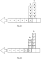
- FIG. 21 shows an image of the collector at the instant 0
- FIG. 22 shows an image of the collector at the instant 1
- FIG. 23 shows an image of the collector at the instant 2
- FIG. 24 shows an image of the collector at the instant 3
- FIG. 25 shows an example of a FIFO list associated with three lanes
- FIG. 26 shows an achievable sequence, expected on the collector
- FIG. 27 shows the first load of the flow attached to the injection point, forming part of the FIFO list
- FIG. 28 shows the first load of the flow not attached to the injection point, not forming part of the FIFO list
- FIG. 29 shows loads on continuous hold behind a first load forming part of the FIFO list
- FIG. 30 shows loads on continuous hold behind a first load not forming part of the FIFO list
- FIG. 31 shows an example of a work batch
- FIG. 32 shows a computation of the dates of injection and processing of the batch 1 ;
- FIG. 33 shows the processing of a batch in progress
- FIG. 34 shows the end of processing of the batch 1 and the formation of the batch 2 ;
- FIG. 35 shows the end of processing of the batch 2 and its application
- FIG. 36 is a chart of the algorithm in the general case with non-controlled disturbing flow
- FIG. 37 shows an example of a disturbing flow: grey-colored loads returning to the PTS;
- FIG. 38 shows an example of a collector with four unspecified lanes with non-controlled disturbing flow
- FIG. 39 is a Gantt chart with non-controlled disturbing flow forming spaces
- FIG. 40 is a chart of algorithm 4.
- FIG. 41 shows an example of a collector with four lanes placed in any unspecified way with controlled disturbing flow
- FIG. 42 is a Gantt chart of the injections showing the spaces to be used for the disturbing loads
- FIG. 43 is a Gantt chart when choosing the placing of the disturbing loads
- FIG. 44 shows a structure of a control system according to one particular embodiment of the invention.
- FIG. 45 is a chart of the algorithm 5.
- FIG. 46 is a flowchart of a method of merging k incoming flows into one outgoing flow, according to a first particular embodiment based on the algorithm 2;
- FIG. 47 is a flowchart of a method of merging k incoming flows into one outgoing flow, according to a second particular embodiment based on the algorithm 3 (illustrated in FIG. 36 );
- FIG. 48 is a flowchart of a method of merging k incoming flows into one outgoing flow, according to a third particular embodiment based on the algorithm 4 (illustrated in FIG. 40 );
- FIG. 49 is a flowchart of a method of merging k incoming flows into one outgoing flow, according to a fourth particular embodiment based on the algorithm 5 (illustrated in FIG. 45 );
- FIG. 50 shows an example of an application.
- the system under study is formed by a drain-off system (a conveyor called a collector), several other conveyors (called lanes) and loads.
- the system is dynamic, and the loads are transported by the lanes, injected into the collector and then transported by the collector.
- a drain-off system a conveyor called a collector
- lanes several other conveyors
- loads are transported by the lanes, injected into the collector and then transported by the collector.
- a first stage we shall consider the state of this system in freezing the position of each load present in it at a given instant.
- Section 7 shall examine the way to control and steer this system dynamically.
- FIG. 2 is an image illustrating two lanes (conveyors) 2 1 , 2 2 , one collector 1 and one load (box or carton) 6 .
- FIG. 3 is a modelized view of the elements appearing in the image of FIG. 2 (and keeps the same numerical references).
- the date 0 Date as which we can start injecting the loads into the collector (date taking the form of the first unoccupied location on this collector)
- each lane will comprise an ordered set of loads.
- k be the number of lanes in our system, each lane being numbered ⁇ 1 to ⁇ k in the sense of movement of the collector.
- These lanes respectively possess a number h i of loads represented by a First-In-First-Out (FIFO) list that has to be injected one by one into the collector.
- FIFO First-In-First-Out
- FIG. 4 An example is given in FIG. 4 .
- the sense of movement of the collector 1 is from right to left, this direction being indicated by the arrow.
- Each lane is numbered and comprises ordered loads which will have to be injected one by one, from bottom to top, into the collector.
- ⁇ be the exit sequence in which these loads must be ordered once they are all injected into the collector.
- the function ⁇ (u) gives the position of the load u in this sequence.
- Each load can thus be identified by a single “sequence” number between 1 and n, corresponding to its position in the desired exit sequence ( ⁇ ). This is how we will identify the loads here below. It can be noted that, in this case, it is easy to verify if the sequence is achievable: it is enough for each lane to have an ordered list of loads identified by sequence numbers in rising order that are not necessarily consecutive.
- each lane corresponds to an injection flow at a given instant, represented as a FIFO column attached to the collector.
- departure point denote the place at which this load awaits the order to depart from its lane (conveyor), illustrated by a point attached to the FIFO column
- injection point denote the space of the collector that is the first to be touched by the load in the course of being really injected into this collector, illustrated by a dot attached to the collector in FIG. 6 .
- the drain-off system (or collector) will be considered as a system with time spans (like a sorter) also called slots or positions.
- FIG. 8 illustrates the sub-division into time spans (positions or slots) of the collector.
- time span corresponds to the duration needed for a point of the collector to move exactly by the physical distance corresponding to one position.
- the distance defined for this position corresponds to the size of a load plus a security distance. This security distance must be adjusted according to the needs of those skilled in the art and in order to comply with the following condition (illustrated in FIG. 10 ).
- the time unit must obligatorily be greater than the time taken by a load to be injected into the collector from the time when a part of the load touches the collector up to the time when the entire load is placed accurately on the collector (i.e. in its flow).
- the time distance between two lanes a i and a j is denoted as ⁇ i,j , the second index being the lane relative to which operation is situated.
- Each load of the sequence ⁇ u (u th load of this sequence) is associated with a job J u and each lane ⁇ i is associated with a machine M i .
- Each job J u associated with a load contained in the lane ⁇ i must follow an ordered list of k ⁇ i+1 unit operations ⁇ o u,i , o u, ⁇ i+1 ⁇ , . . . , o u,k ⁇ .
- An operation denoted as o u,i is a unit job of the job J u to be performed specifically on the machine M i .
- a job can be assigned to only one machine at a time and a machine can carry out only one operation at a time.
- Each of then loads is associated with a job J u , u ⁇ 1, . . . , n ⁇ , with numbering in accordance with the sequence number of the load.
- ⁇ u corresponds to the u th load in the sequence ⁇
- its associated job is J u .
- the operations of these jobs must be processed by a set of k machines ⁇ M 1 , . . . , M k ⁇ .
- An operation can be allotted to only one machine at a time.
- Each machine is associated with a lane (i.e. an injection flow) that can carry out only one operation at a time. It may be recalled that these lanes are numbered ⁇ 1 , . . . , ⁇ k ⁇ , from upstream to downstream (i.e. according to the sense of conveyance of the collector).
- a load ⁇ u being injected into the collector from the lane ⁇ i will pass in front of each lane a j with j in ⁇ i, i+1, . . . , k ⁇ .
- This mechanism is represented by the fact that each job associated with a load of the lane ⁇ i is composed of k ⁇ i+1 unit operations ⁇ o u,i , o u, ⁇ i+1 ⁇ , . . . , o u,k ⁇ to be processed consecutively without waiting. Each operation has to be scheduled on a specific machine.
- the starting instants of the following operations (c.-à-d. ⁇ o u ⁇ i+1 ⁇ , . . . , o u,k ⁇ ) represent the instants at which the load is in front of the following lanes.
- each job is composed of at least one operation on the last machine M k (since each load passes in front of at least the last lane ⁇ k ).
- the sequence of the operations scheduled on the machine M k corresponds exactly to the order in which the loads will pass in front of the last lane and their departure date corresponds to the instant when these loads will pass in front of this last injection lane. This is why, if the load u is before the load v in the given exit sequence, the last operation of u must begin before the last operation of v on M k .
- the goal of not having space on the collector amounts to not having idle time between the operations of the machine M k .
- the real dates of injection into the collector are deduced directly from the start of the first operation of each job.
- the time unit used is the one defined here above (“the time span” of the collector).
- the algorithm 1 here below gives the dates of injection T(u), i.e. the dates of entry of each load u into the collector.
- the time unit used is the “time span” defined further above.
- the algorithm 1 gives the formula for computing these injection dates should the flows get injected at each consecutive location on the collector (see FIG. 14 ).
- the Gantt chart is a very useful tool for viewing, in time, the operations composing a job. This tool will enable us to graphically represent the progress of the work of each machine and visually show us the solution provided to our problem. In addition, we can see the link between the results obtained by the algorithm enabling the injection dates to be attained and the associated formula.
- each row corresponds to one machine.
- the fact that each load passes by the machines consecutively is represented by the fact that each load sequence number appears in consecutive boxes from left to right in the table (see FIG. 15 ).
- the algorithm 2 here below takes account of this notion of any unspecified time distance between lanes and thus responds to the general case of the collector dedicated to injection flows.
- FIG. 46 presents a flowchart of the method for merging k incoming flows into one outgoing flow, according to a first particular embodiment based on the algorithm 2.
- the method is executed at least once by the control system.
- a given execution is performed at an instant Tb and comprises the following steps:
- inter-lane distances that are integer values but it is possible to take non-integer values in numbers of “time spans”.
- Each injection flow (incoming flow) is represented by a lane containing a list of loads in a FIFO order.
- the number of lanes can vary from 2 to k, and the list of the lane i contains h i loads (h i can be zero).
- h i can be zero
- the numbers indicated are not sequence numbers within the final sequence but sequential order numbers relative to customer orders to be picked.
- This sequence ⁇ ′ can be seen as a given exit sequence for the algorithm which computes the injection dates. This sequence is obligatorily achievable and minimizes the disorder. We obtain a maximum throughput with a minimum disorder for the outgoing flow from the collector.
- FIGS. 19 and 20 are equivalent.
- the exit sequence ⁇ (1,2,3,4,5,6,7,8,9,10) truly makes it possible to see the rising order of loads on each injection flow (proof of feasibility of the sequence).
- L′ brings together the loads numbered 1 and 5.
- each load u appears for the first time on the collector at the date T(u) (its injection date).
- the load 2 must be injected at the instant 1, which means that it is on the collector after the movement by one step of the collector, as is shown by FIG. 22 .
- the load 3 is injected at the instant 2, as is shown by FIG. 23 .
- the loads 4 and 5 are injected at the date 3, as is shown by FIG. 24 .
- the computation of the injection dates is done on a given state of the system.
- a first possibility consists in redoing this computation whenever a new load arrives at the system because it has does not yet have its definite injection date.
- it is preferable to proceed by batches. This kind of batchwise operation is explained in this section.
- each lane there is a list of loads with a unique sequence number for each load.
- sequence numbers of the loads are obligatorily numbers that are rising by lane but not necessarily consecutive (due to the definition of the achievable sequence to be given).
- FIG. 25 illustrates an example of a FIFO list associated with three lanes.
- FIG. 26 illustrates the final achievable sequence, awaited on the collector.
- each lane corresponds to an injection flow represented as a FIFO column attached to the collector, with its injection point defined by a black dot on the diagrams.
- the FIFO list of the loads taken into account in a lane for a fixed configuration of the system sets the order of the loads waiting at the injection point of this lane in accordance with the following conditions:
- a work batch corresponds to the set of loads of the FIFO list of all the lanes (it is the set L of n loads). However, these loads correspond to the static photograph of our system at a given instant, complying with the rules of the preceding paragraph. The loads present in the system at this instant, which do not comply with the rules of filling of FIFO lists, will be assigned later to another batch. Once the loads of the batch are all allotted, the injection dates for this batch are computed. The injection of these loads is done as and when the time passes, in complying with the injection dates computed beforehand. The system develops in the course of time, without again calling the injection date computation algorithm, although new loads are eligible under the rules of filling of the FIFO lists or even if new loads appear in the system.
- All these injection dates are computed in order to succeed in placing each load of the batch at a reserved place on the conveyor, in complying with the order of the desired final sequence, while at the same time minimizing the vacant spaces.
- the last loads of the exit sequence of the preceding batch can be considered for the new batch (following batch). In this case, if a load at the position i in the exit sequence is put back into the next batch, then so too are all the loads having positions greater than i). However, it is worthwhile to take up the loads again only if the desired final sequence has changed. In this case, the last place p considered will be the place of the last load not taken up in the next batch. For the loads that are taken up, the injection dates already defined in the preceding batch will be obsolete and replaced by dates of injection computed for the next batch.
- the first batch will be composed of the loads: 1, 2, 3, 4, 5, 6, 7, 8, 9.
- the following batch could be: xx, yy or 9, xx, yy, . . . , or again 7, 8, 9, xx, yy, . . . (but not 8, xx, yy, nor 7, 9, xx, yy).
- the processing of each batch is done continuously and in series (batch1, batch2, etc.).
- the processing of a batch is a static computation of all the dates of injection of the loads composing this batch.
- the linking and the building of these batches provides a comprehensive solution to the problem of merging the incoming flows into one outgoing flow in the warehouses, which is a dynamic problem.
- This batch is constituted by all the valid loads of each FIFO list of each lane according to the rules explained further above.
- FIG. 34 illustrates the formation of the next batch composed of six new loads that have appeared on the lanes and are numbered 1 to 6 (sequence numbers of the new exit sequence desired for the new batch).
- the algorithm for computing the static injection dates is applied to this new batch in considering the unoccupied part of the collector (to the right of the place reserved for the load numbered 9 of the previous batch).
- the injection dates are computed as a function of a time scale, the origin of which corresponds to the first injection of a load of the new batch.
- the configuration of the static system taken at the “Time 5 ” as can be seen in FIG. 34 , is given (as input data) to the algorithm.
- the date 0 is fixed by simultaneous injection of two new loads numbered 1 and 4 (into the lanes a 2 and a 1 respectively). Since this origin of time, the algorithm gives a date of injection T(u) for each of the six new loads u of this new batch.
- Each load of each batch will be given an injection date as a function of an origin of time that is well specified in relation to the static system. These injection dates must be placed at the right instant in the dynamic configuration to be consistent with the dynamic solution.
- a time scale common to all the batches makes it possible to link the injections of all the loads into the dynamic system.
- the time unit of this time scale is the “time span” of the collector, as defined further above. Let “Time” be the time derived from this common time scale, with the time 0 representing the starting date of the operations in the system.
- the injection dates given by the algorithm must be repositioned correctly in this common time scale. To this end, it is necessary to find the time-related correspondence, in the dynamic system, of the situation described at the date 0 of the batch. This means that it is necessary to obtain a correspondence between the date 0 of the batch and the Time of the common scale truly enabling the first injection of the load of this batch. It is then necessary to shift all the injection dates of this batch exactly this time.
- Time also called “Tb”
- ⁇ * the time at which the algorithm call has been launched
- the disturbing loads of the disturbing flow block the injection of a payload into the collector when they pass in front of the injection lanes. It is therefore necessary to compute the non-valid dates not valid for an injection of a payload for each lane.
- the idea is to take account of the disturbing loads and/or other obstructions to compute the dates not valid for an injection of a payload of a lane.
- the non-valid dates are obtained by computing the instants of passage of each obstruction (i.e. each disturbing load of the disturbing flow or any other obstruction) in front of this injection lane.
- U i denote the set of non-valid dates where the lane a i cannot inject a payload because of the disturbing loads and/or any unspecified obstructions of the time spans of the collector.
- the real dates of injection of the payloads on the collector are deduced directly from the start of the first operation of each job.
- the time unit used is the one defined further above.
- this is the approach followed in the general case to compute the real dates of injection during the merger of several flows comprising incoming flows (injection flows) and (at least) one non-controlled disturbing flow.
- the real dates of injection of the payloads into the collector are deduced directly from the start of the first operation of each job.
- the time unit used is the one defined further above.
- the algorithm 3 here below computes the dates of injection of the payloads in taking account of the disturbing flow that takes the form of the dates of prohibition of injection by lane.
- the date 0 corresponds to the first load injected into the collector at the earliest.
- the date t 0 is always the date at which the first load of the sequence passes in front of the lane a k .
- the algorithm 3 gives the date of injection of each load in taking account of the disturbing flow and in correcting the date t 0 if necessary.
- FIG. 36 is a graph of the algorithm 3 here above.
- FIG. 47 presents a flowchart of a method for merging k incoming flows into one outgoing flow according to a second particular embodiment based on the algorithm 3 (illustrated in FIG. 36 ).
- the method is executed at least once by the control system.
- a given execution is performed at an instant Tb and comprises the following steps:
- FIG. 37 illustrates this configuration with the disturbing loads (marked by a cross) of the return flow (constituting the non-controlled disturbing flow) that returns to the automated system (PTS).
- g p 1 and l p ⁇ k, for every load p of the return flow specific to the automated system (PTS).
- PTS automated system
- the disturbing load B obliges the payload 4 to shift in time by one position and will leave a vacant space in the final flow of the collector. Then, the disturbing flow C obliges the payload 7 to shift by yet another position, leaving a vacant space later in the final flow of the collector.
- FIG. 39 is a Gantt chart illustrating the solution proposed in this case.
- the first vacant space could be filled by the lane ⁇ 3 or ⁇ 4 and the second vacant space solely by the lane ⁇ 4 .
- vacant spaces would be avoided, and the throughput of the final flow (outgoing flow) from the collector would be increased.
- the algorithm 4 described in detail here below gives the injection dates of the payloads as well as the control of the disturbing flow.
- the loads to be injected constitute the final flow of the collector. Their injection is decided without taking account of the disturbing flow. Then, we shall determine when to let through the loads of the disturbing flow in considering this time that the injected payloads play the same role as the non-controlled flow in the algorithm 3 here above. Thus, we can use the same technique as here above with the computation of the sets
- ⁇ ′ p,p′ gives the distance between the disturbing loads p and p′ at the date 0 and t r gives the date, without waiting, of arrival of the 1 st load of the disturbing flow in front of the lane number a 1 .
- FIG. 40 is a diagram of the algorithm 4 here above.
- FIG. 48 presents a flowchart of a method for merging k incoming flows into one outgoing flow, according to a third particular embodiment based on the algorithm 4 (illustrated in FIG. 40 ).
- the method is executed at least once by the driving system.
- a given execution is performed at an instant Tb and comprises the following steps:
- FIG. 42 is an illustration, in the form of a Gantt chart, of the solution without taking account of the disturbing flow (“pure injection solution”).
- FIG. 43 is an illustration, in the form of a Gantt chart, of the solution proposed to control the disturbing flow (i.e. by choosing the placing of the disturbing loads).
- the loads B and C no longer form a vacant space in the final flow of the collector. They have been interposed at strategic places so that the vacant space that they leave initially is then filled by an injection of a time-compatible load. Through the control of the disturbing flow, we have shown that the vacant spaces on the collector are avoidable.
- ⁇ ′ p designate the distance between each disturbing load p ⁇ S and the last lane ⁇ k at the date Tb and let g′ p and l′ p respectively designate the number of the first and last lane in front of which the disturbing load p must pass.
- ⁇ p designate the distance from each disturbing load p ⁇ F to the last lane ⁇ k at the date Tb and let g p and l p respectively denote the number of the first and last lane in front of which the disturbing load p must pass.
- the algorithm 5 provides a detailed view here below of the dates of injection of the payloads as well as the control of the disturbing flow, in taking account of the non-controlled disturbing flow.
- Algorithm 5 Computation of the injection dates of the payloads and the loads of the controlled disturbing flow with the non-controlled disturbing flow being taken into account: Require: F, S, ⁇ , ⁇ i , ⁇ 1i , a i (j), ⁇ i ⁇ ⁇ 1, . . . , k ⁇ , ⁇ j ⁇ ⁇ 1, . . .
- FIG. 45 is a diagram of the algorithm 5 here above.
- FIG. 49 is a flowchart of a method for merging k incoming flows into one outgoing flow, according to a fourth particular embodiment based on the algorithm 5 (illustrated in FIG. 45 ).
- the method is executed at least once by the control system.
- a given execution is performed at an instant Tb and comprises the following steps:
- An algorithm has also been given to manage at least one non-controlled flow (obstructions that are not obligatorily disturbing loads) and, at the same time, at least one controlled flow (disturbing loads).
- the proposed solution is a method of merging, within a logistical warehouse, k incoming flows of payloads, transported respectively by k conveyors called lanes ⁇ i with i ⁇ 1, . . . , k ⁇ , into one outgoing flow of payloads transported by another conveyor called a collector.
- the method of merger is executed by a control system.
- a control system This is for example a central warehouse control system or WCS.
- FIG. 44 presents the structure of the control system 90 according to one particular embodiment of the invention.
- This control system comprises a live memory 92 (for example a RAM), a processing unit 91 equipped for example with a processor and controlled by a computer program 930 stored in a read-only memory 93 (for example a ROM or a hard disk drive).
- a live memory 92 for example a RAM
- a processing unit 91 equipped for example with a processor and controlled by a computer program 930 stored in a read-only memory 93 (for example a ROM or a hard disk drive).
- a read-only memory 93 for example a ROM or a hard disk drive
- the code instructions of the computer program are for example loaded into the live memory 92 and then executed by the processor of the processing unit 91 , to implement the method of merger of the invention (according to any one of the different embodiments described here above).
- the processing unit 91 inputs pieces of information 94 pertaining to the incoming flows.
- the processor of the processing unit 91 processes the information 94 and generates at exit instructions or commands 95 used to control (command) different elements included in the system, especially the lanes, the collector, the control means, etc.
- FIG. 44 illustrates only one particular way, among several possible ways, of carrying out the technique of the invention in any one of its embodiments. Indeed, the control system is obtained equally well on a reprogrammable computing machine (for example a PC computer, a DSP processor, a microcontroller, etc.) executing a program comprising a sequence of instructions, or on a dedicated computing machine (for example a set of logic gates such as an FPGA or an ASIC or any other hardware module).
- a reprogrammable computing machine for example a PC computer, a DSP processor, a microcontroller, etc.
- a dedicated computing machine for example a set of logic gates such as an FPGA or an ASIC or any other hardware module.
- the corresponding program i.e. the sequence of instructions
- a storage medium that it detachable (such as for example a floppy disk, a CD-ROM or a DVD-ROM) or non-detachable, this storage medium being partially or totally readable by a computer or a processor.
Landscapes
- Engineering & Computer Science (AREA)
- Business, Economics & Management (AREA)
- Economics (AREA)
- Human Resources & Organizations (AREA)
- Strategic Management (AREA)
- General Physics & Mathematics (AREA)
- Physics & Mathematics (AREA)
- Entrepreneurship & Innovation (AREA)
- Mechanical Engineering (AREA)
- Operations Research (AREA)
- General Business, Economics & Management (AREA)
- Theoretical Computer Science (AREA)
- Marketing (AREA)
- Tourism & Hospitality (AREA)
- Quality & Reliability (AREA)
- Development Economics (AREA)
- Game Theory and Decision Science (AREA)
- Automation & Control Theory (AREA)
- Educational Administration (AREA)
- Finance (AREA)
- Accounting & Taxation (AREA)
- Control Of Conveyors (AREA)
- Warehouses Or Storage Devices (AREA)
- Control Of Position, Course, Altitude, Or Attitude Of Moving Bodies (AREA)
- Management, Administration, Business Operations System, And Electronic Commerce (AREA)
Applications Claiming Priority (4)
| Application Number | Priority Date | Filing Date | Title |
|---|---|---|---|
| FR1912231 | 2019-10-30 | ||
| FR1912231A FR3103182A1 (fr) | 2019-10-30 | 2019-10-30 | Procédé de fusion, au sein d’un entrepôt logistique, de k flux entrants de charges utiles en un flux sortant. |
| FR1912777A FR3103296B1 (fr) | 2019-10-30 | 2019-11-15 | Procédé de fusion, au sein d’un entrepôt logistique, de k flux entrants de charges utiles en un flux sortant |
| FR1912777 | 2019-11-15 |
Publications (2)
| Publication Number | Publication Date |
|---|---|
| US20210130107A1 US20210130107A1 (en) | 2021-05-06 |
| US11795009B2 true US11795009B2 (en) | 2023-10-24 |
Family
ID=72826820
Family Applications (1)
| Application Number | Title | Priority Date | Filing Date |
|---|---|---|---|
| US17/083,887 Active 2042-06-16 US11795009B2 (en) | 2019-10-30 | 2020-10-29 | Method for merging, within a logistical warehouse, k incoming flows of payloads into one outgoing flow |
Country Status (7)
| Country | Link |
|---|---|
| US (1) | US11795009B2 (da) |
| EP (1) | EP3816896B1 (da) |
| CN (1) | CN112749830B (da) |
| CA (1) | CA3097401C (da) |
| DK (1) | DK3816896T3 (da) |
| ES (1) | ES2962842T3 (da) |
| PL (1) | PL3816896T3 (da) |
Families Citing this family (3)
| Publication number | Priority date | Publication date | Assignee | Title |
|---|---|---|---|---|
| CN114560213B (zh) * | 2021-12-10 | 2024-01-19 | 福建省烟草公司莆田市公司 | 一种自动仓储配发一体化系统 |
| CN115610988B (zh) * | 2022-11-07 | 2023-06-09 | 湖南视比特机器人有限公司 | 自动分拣码垛输送系统和自动控制方法 |
| CN121303637A (zh) * | 2025-09-10 | 2026-01-09 | 九江学院 | 一种考虑机器老化的柔性作业车间动态调度方法及系统 |
Citations (10)
| Publication number | Priority date | Publication date | Assignee | Title |
|---|---|---|---|---|
| US4501528A (en) * | 1982-04-07 | 1985-02-26 | Ing. Gunter Knapp Ges. Mbh & Co. Kg | System for automatic stacking, storage and withdrawal of packaged merchandise in large warehouses |
| US20060245858A1 (en) * | 2005-01-18 | 2006-11-02 | Heiko Suess | Apparatus for forming a sequence of load carriers by means of a temporary store, and method for temporary storage |
| US8327609B2 (en) * | 2007-05-11 | 2012-12-11 | Savoye | Automated system for preparing parcels |
| WO2013150080A1 (fr) | 2012-04-04 | 2013-10-10 | Savoye | Systeme et procede de traitement d'une commande |
| US20130275236A1 (en) * | 2012-04-13 | 2013-10-17 | Sealed Air Corporation (Us) | Fresh Departments Management System |
| US20140195032A1 (en) * | 2013-01-09 | 2014-07-10 | Hauni Maschinenbau Ag | Method for the demand-controlled supply to and disposal away from at least two production stations of the tobacco processing industry with full and/or empty transport units |
| US9771218B2 (en) * | 2014-02-19 | 2017-09-26 | Dematic Gmbh | Method and station for picking articles according to the goods-to-man principle |
| US10239704B2 (en) * | 2014-06-24 | 2019-03-26 | Tgw Logistics Group Gmbh | Method and conveying technology element for combining conveyor streams in a conveyor system |
| US10280001B2 (en) * | 2012-11-15 | 2019-05-07 | Amazon Technologies, Inc. | Bin-module based automated storage and retrieval system and method |
| US20200102146A1 (en) * | 2016-11-16 | 2020-04-02 | Savoye | Method for sequencing loads in an automated distribution system |
Family Cites Families (5)
| Publication number | Priority date | Publication date | Assignee | Title |
|---|---|---|---|---|
| CN102673816B (zh) * | 2012-06-11 | 2015-05-20 | 姜广峻 | 货物分拣分装设备 |
| TWI777945B (zh) * | 2016-03-15 | 2022-09-21 | 德商阿莫瓦有限公司 | 用於在高架倉庫中貯存和獲取或者重排貯存品的運輸和轉移系統 |
| FR3051948B1 (fr) * | 2016-05-30 | 2021-01-01 | Savoye | Systeme de stockage tampon et de sequencement de charges comprenant deux elevateurs. |
| JP6677115B2 (ja) * | 2016-07-21 | 2020-04-08 | 株式会社ダイフク | 物品並べ替え装置及びそれを備えた物品保管設備 |
| CN110111048B (zh) * | 2019-04-29 | 2021-11-09 | 西安电子科技大学 | 仓储系统中的订单任务调度方法 |
-
2020
- 2020-10-20 PL PL20202699.3T patent/PL3816896T3/pl unknown
- 2020-10-20 EP EP20202699.3A patent/EP3816896B1/fr active Active
- 2020-10-20 DK DK20202699.3T patent/DK3816896T3/da active
- 2020-10-20 ES ES20202699T patent/ES2962842T3/es active Active
- 2020-10-29 CA CA3097401A patent/CA3097401C/fr active Active
- 2020-10-29 US US17/083,887 patent/US11795009B2/en active Active
- 2020-10-30 CN CN202011190697.5A patent/CN112749830B/zh active Active
Patent Citations (11)
| Publication number | Priority date | Publication date | Assignee | Title |
|---|---|---|---|---|
| US4501528A (en) * | 1982-04-07 | 1985-02-26 | Ing. Gunter Knapp Ges. Mbh & Co. Kg | System for automatic stacking, storage and withdrawal of packaged merchandise in large warehouses |
| US20060245858A1 (en) * | 2005-01-18 | 2006-11-02 | Heiko Suess | Apparatus for forming a sequence of load carriers by means of a temporary store, and method for temporary storage |
| US8327609B2 (en) * | 2007-05-11 | 2012-12-11 | Savoye | Automated system for preparing parcels |
| WO2013150080A1 (fr) | 2012-04-04 | 2013-10-10 | Savoye | Systeme et procede de traitement d'une commande |
| US9205981B2 (en) | 2012-04-04 | 2015-12-08 | Savoye | System and method for processing a command |
| US20130275236A1 (en) * | 2012-04-13 | 2013-10-17 | Sealed Air Corporation (Us) | Fresh Departments Management System |
| US10280001B2 (en) * | 2012-11-15 | 2019-05-07 | Amazon Technologies, Inc. | Bin-module based automated storage and retrieval system and method |
| US20140195032A1 (en) * | 2013-01-09 | 2014-07-10 | Hauni Maschinenbau Ag | Method for the demand-controlled supply to and disposal away from at least two production stations of the tobacco processing industry with full and/or empty transport units |
| US9771218B2 (en) * | 2014-02-19 | 2017-09-26 | Dematic Gmbh | Method and station for picking articles according to the goods-to-man principle |
| US10239704B2 (en) * | 2014-06-24 | 2019-03-26 | Tgw Logistics Group Gmbh | Method and conveying technology element for combining conveyor streams in a conveyor system |
| US20200102146A1 (en) * | 2016-11-16 | 2020-04-02 | Savoye | Method for sequencing loads in an automated distribution system |
Non-Patent Citations (5)
| Title |
|---|
| English Translation of French Written Opinion dated Mar. 26, 2020 for French Application No. 1912777, filed Nov. 15, 2019. |
| French Search Report and Written Opinion dated Mar. 26, 2020 for French Application No. 1912777, filed Nov. 15, 2019. |
| Imran Ali Chaudhry and Abid Ali Khan, "A research survey: review of flexible job shop scheduling techniques", International transactions in operation research, 2015. |
| Koster et al., "Design and control of warehouse order picking: a literature review" (2007), European Journal of Operational Research 182(2), 481-501. |
| Runwey Cheng, Mitsuo Gen and Yasuhiro Tsujimura, "A tutorial survey of Job Shop scheduling problems using genetic algorithms—Part I. Representation", Ashikaga Institute of Technology, Ashikaga 326, Japan. |
Also Published As
| Publication number | Publication date |
|---|---|
| CN112749830B (zh) | 2024-04-26 |
| CN112749830A (zh) | 2021-05-04 |
| US20210130107A1 (en) | 2021-05-06 |
| CA3097401C (fr) | 2023-04-18 |
| ES2962842T3 (es) | 2024-03-21 |
| EP3816896B1 (fr) | 2023-09-06 |
| CA3097401A1 (fr) | 2021-04-30 |
| EP3816896A1 (fr) | 2021-05-05 |
| PL3816896T3 (pl) | 2024-04-15 |
| DK3816896T3 (da) | 2023-11-13 |
Similar Documents
| Publication | Publication Date | Title |
|---|---|---|
| US11795009B2 (en) | Method for merging, within a logistical warehouse, k incoming flows of payloads into one outgoing flow | |
| Boysen et al. | Optimizing automated sorting in warehouses: The minimum order spread sequencing problem | |
| US4244672A (en) | System for sequencing articles including mail | |
| JP7161957B2 (ja) | 物品搬送システム及び物品搬送方法 | |
| US5467285A (en) | Method and system for optimizing material movement within a computer based manufacturing system | |
| US9205982B2 (en) | Distribution warehouse and method for arranging different articles in an order-oriented manner by means of a reduced buffer | |
| CN109313731B (zh) | 包括两个升降机的缓冲存储和物件排序的系统 | |
| CN115744014B (zh) | 一种巷道仓储管理方法、系统及设备 | |
| CN111985756B (zh) | 用于在客户订单准备系统中处理客户订单列表的方法及系统 | |
| US11117745B2 (en) | Method for sequencing loads in an automated distribution system | |
| US7801640B1 (en) | Continuous item picking in a distribution center using coordinated item picking periods | |
| Yu | Enhancing warehouse performance by efficient order picking | |
| CN111115149B (zh) | 用于在分类模式下管理缓冲存储和负载排序系统的方法,和对应管理单元 | |
| Lienert et al. | Routing-based sequencing applied to shuttle systems | |
| US11319162B2 (en) | Method for the management, in flow mode, a buffer storage and load sequencing system, and corresponding management unit | |
| Truong et al. | Building management algorithms in automated warehouse using continuous cluster analysis method | |
| RU2749385C1 (ru) | Способ определения входящих потоков грузов в один исходящий поток на логистическом складе | |
| KR102861194B1 (ko) | 주문 자동화 처리를 위한 방법 및 장치 | |
| KR102909214B1 (ko) | 자동화 주문처리 방법 및 자동화 주문처리 장치 | |
| JP2001225914A (ja) | 自動倉庫管理システム | |
| EP4600879A1 (en) | Mobile unit management device, management method, and storage medium that stores management program | |
| JP2004001944A (ja) | 入出庫制御方法及び装置並びにその入出庫制御装置を有する自動倉庫 | |
| RU2772437C1 (ru) | Узел распределения изделий и автоматизированная система распознавания изделий | |
| US20250086567A1 (en) | Transportation and delivery planning apparatus and method | |
| JP2020045194A (ja) | 搬送システム |
Legal Events
| Date | Code | Title | Description |
|---|---|---|---|
| FEPP | Fee payment procedure |
Free format text: ENTITY STATUS SET TO UNDISCOUNTED (ORIGINAL EVENT CODE: BIG.); ENTITY STATUS OF PATENT OWNER: LARGE ENTITY |
|
| STPP | Information on status: patent application and granting procedure in general |
Free format text: APPLICATION DISPATCHED FROM PREEXAM, NOT YET DOCKETED |
|
| AS | Assignment |
Owner name: UNIVERSITE DE TECHNOLOGIE DE COMPIEGNE, FRANCE Free format text: ASSIGNMENT OF ASSIGNORS INTEREST;ASSIGNORS:VACHER, BLANDINE;PIETROWICZ, STEPHANE;JOUGLET, ANTOINE;AND OTHERS;SIGNING DATES FROM 20201115 TO 20201122;REEL/FRAME:054516/0913 Owner name: SAVOYE, FRANCE Free format text: ASSIGNMENT OF ASSIGNORS INTEREST;ASSIGNORS:VACHER, BLANDINE;PIETROWICZ, STEPHANE;JOUGLET, ANTOINE;AND OTHERS;SIGNING DATES FROM 20201115 TO 20201122;REEL/FRAME:054516/0913 |
|
| STPP | Information on status: patent application and granting procedure in general |
Free format text: DOCKETED NEW CASE - READY FOR EXAMINATION |
|
| STPP | Information on status: patent application and granting procedure in general |
Free format text: NOTICE OF ALLOWANCE MAILED -- APPLICATION RECEIVED IN OFFICE OF PUBLICATIONS |
|
| STPP | Information on status: patent application and granting procedure in general |
Free format text: PUBLICATIONS -- ISSUE FEE PAYMENT VERIFIED |
|
| STCF | Information on status: patent grant |
Free format text: PATENTED CASE |