US11793929B2 - Split piston metering pump - Google Patents
Split piston metering pump Download PDFInfo
- Publication number
- US11793929B2 US11793929B2 US16/685,847 US201916685847A US11793929B2 US 11793929 B2 US11793929 B2 US 11793929B2 US 201916685847 A US201916685847 A US 201916685847A US 11793929 B2 US11793929 B2 US 11793929B2
- Authority
- US
- United States
- Prior art keywords
- piston
- drive
- floating piston
- pump housing
- drive piston
- Prior art date
- Legal status (The legal status is an assumption and is not a legal conclusion. Google has not performed a legal analysis and makes no representation as to the accuracy of the status listed.)
- Active, expires
Links
Images


Classifications
-
- A—HUMAN NECESSITIES
- A61—MEDICAL OR VETERINARY SCIENCE; HYGIENE
- A61M—DEVICES FOR INTRODUCING MEDIA INTO, OR ONTO, THE BODY; DEVICES FOR TRANSDUCING BODY MEDIA OR FOR TAKING MEDIA FROM THE BODY; DEVICES FOR PRODUCING OR ENDING SLEEP OR STUPOR
- A61M5/00—Devices for bringing media into the body in a subcutaneous, intra-vascular or intramuscular way; Accessories therefor, e.g. filling or cleaning devices, arm-rests
- A61M5/14—Infusion devices, e.g. infusing by gravity; Blood infusion; Accessories therefor
- A61M5/142—Pressure infusion, e.g. using pumps
- A61M5/14212—Pumping with an aspiration and an expulsion action
- A61M5/14216—Reciprocating piston type
- A61M5/1422—Reciprocating piston type with double acting or multiple pistons
Definitions
- the present invention is directed to a micropump adapted for the continuous delivery of a liquid medication by infusion such as may be used in the delivery of insulin for the treatment of diabetes.
- Micropumps for subcutaneous delivery of drugs are known, for example, from U.S. Pat. Nos. 7,726,955 and 8,282,366.
- This prior art describes, in various embodiments, a pump having a rotor mounted in a stator, or housing. Sealing rings situated at an angle on axial extensions on the rotor cooperate with channels formed between the rotor and the stator to move liquid in precise amounts through a rotor housing.
- these embodiments are relatively complex and not cost effective. The user keeps the pump when the infusion patch is changed for several weeks.
- the need for compact and economical micropump designs remains acute.
- Another infusion pump known in the prior art comprises a rigid reservoir with a lead screw engaged in the reservoir to dispense medication through a cannula as the lead screw advances.
- the actuator for delivery of the medication is directly connected to the lead screw and dosing precision depends on variables that are difficult to control, such as the precision of the motor.
- the device requires the rigid reservoir to provide calibrated dosages. Thus, it is impossible to use a flexible reservoir and the number of possible layouts for the pump is consequently limited.
- a micropump according to the invention is provided for the delivery of medication by infusion. Although described in connection with delivery of insulin, the micropump may be used for infusion of other medications.
- the micropump comprises: a reservoir; a cannula; a motor; a gear; a drive rack and a tubular pump housing having a first aperture in fluid communication with the reservoir and a second aperture in fluid communication with the cannula.
- a drive piston and a floating piston are axially oriented within the pump housing and positioned to close the first and second aperture at first and second axial positions within the pump housing.
- the motor is engaged to the gear and the gear is engaged to the drive rack to translate the drive piston axially with respect to the floating piston, so that translating the drive piston with respect to the floating piston defines a pump volume space within the pump housing.
- the drive piston is coupled to the floating piston, and the drive rack is axially oriented with respect to the pump housing and coupled to the drive piston to translate the drive piston in the pump housing.
- the drive piston is in a fixed position, the floating piston is not coupled to the drive piston, the drive rack is on the pump housing, and the pump housing is translated by the motor and gear to obtain said first and second axial positions of the drive piston and the floating piston.
- the floating piston (which is also called a “spool” in this embodiment) is provided with an axial bore receiving a portion of the drive piston to define a pump volume space in the bore.
- a through-hole provided on the floating piston opens to the bore and to an outer surface of the floating piston, and is positioned to provide access to the reservoir via the first aperture in the first position and access to the cannula via the second aperture in the second position.
- the gear engages the drive rack through an opening in the pump housing, which permits a shorter axial length of the piston arrangement and a smaller footprint overall.
- the drive piston is provided with an axial extension narrower than a main body portion of the drive piston which is received in a recess at one end of the bore in the floating piston.
- the pump volume space is defined between the axial extension on the drive piston and the end of the recess in the floating piston bore.
- the pump volume space is defined by the relative position of pistons axially arranged in a tubular pump housing.
- the frictional engagement of radial seals on the drive piston and/or the floating piston with the interior surface of the tubular pump housing determines the opening and closing of the apertures in the pump housing to provide access to the reservoir and cannula at different times during the pump cycle.
- FIG. 1 is a schematic overview of the infusion pump according to the invention, including the fluidics and fluid metering subsystems.
- FIG. 2 is an exploded view of the fluid metering subsystem.
- FIG. 3 is a view of an assembled infusion pump according to a first exemplary embodiment of the invention.
- FIG. 4 is a perspective view of the assembled fluid metering system.
- FIG. 5 is a side cross sectional view of the assembled fluid metering system of FIG. 4 .
- FIG. 6 A is a top view of the assembled fluid metering system of FIG. 4 in an initial state prior to the start of the pump cycle.
- FIG. 6 B is a side cross sectional view of the assembled fluid metering system in the initial state of FIG. 6 A .
- FIG. 7 A is a top view of the assembled fluid metering system of FIG. 4 during the intake stroke of the pump cycle.
- FIG. 7 B is a side cross sectional view of the assembled fluid metering system in the state of FIG. 7 A .
- FIG. 8 A is a top view of the assembled fluid metering system of FIG. 4 during a valve state change of the pump cycle.
- FIG. 8 B is a side cross sectional view of the assembled fluid metering system in the state of FIG. 8 A .
- FIG. 9 A is a top view of the assembled fluid metering system of FIG. 4 with the pump volume in a fully expanded state.
- FIG. 9 B is a side cross sectional view of the assembled fluid metering system in the state of FIG. 9 A .
- FIG. 10 A is a top view of the assembled fluid metering system of FIG. 4 during the discharge stroke of the pump cycle.
- FIG. 10 B is a side cross sectional view of the assembled fluid metering system in the state of FIG. 10 A .
- FIG. 11 A is a top view of the assembled fluid metering system of FIG. 4 after the discharge stroke of the pump cycle with the pump volume fully collapsed and the valve changing state.
- FIG. 11 B is a side cross sectional view of the assembled fluid metering system in the state of FIG. 11 A .
- FIG. 12 A and the corresponding cross section of FIG. 12 B show the mechanism returned to the cycle start point.
- FIG. 13 is an exploded view of a fluid metering subsystem according to a second exemplary embodiment of the invention.
- FIG. 13 A is an assembled view of the fluid metering subsystem according to the embodiment of FIG. 13 .
- FIG. 14 is a side cross sectional view of the fluid metering system of FIG. 13 prior to the initiation of the pump cycle.
- FIG. 15 , FIG. 16 , FIG. 17 , FIG. 18 , FIG. 19 , and FIG. 20 depict stages of the pump cycle of the fluid metering system according to the embodiment of FIG. 13 .
- FIG. 21 is an exploded view of a fluid metering subsystem according to a third exemplary embodiment of the invention.
- FIG. 22 is an assembled view of the embodiment of FIG. 21 .
- FIG. 23 is a side cross-sectional view of the embodiment of FIG. 21 .
- FIG. 24 A and the corresponding cross section of FIG. 24 B depict the starting position of the pump cycle according to an embodiment of the invention.
- FIG. 25 A , FIG. 25 B , FIG. 26 A , FIG. 26 B , FIG. 27 A , FIG. 27 B , FIG. 28 A , FIG. 28 B , FIG. 29 A , and FIG. 29 B depict stages of the pump cycle of the fluid metering system according to the embodiment of FIG. 21 .
- FIG. 30 is an exploded view of a fluid metering subsystem according to a fourth exemplary embodiment of the invention.
- FIG. 31 depicts the assembled embodiment of FIG. 30 .
- FIG. 32 is a side cross-sectional view of the embodiment of FIG. 30 .
- FIG. 33 A , FIG. 33 B , FIG. 34 A , FIG. 34 B , FIG. 35 A , FIG. 35 B , FIG. 36 A , FIG. 36 B , FIG. 37 A , FIG. 37 B , FIG. 38 A , FIG. 38 B , FIG. 39 A and FIG. 39 B depict stages of the pump cycle of the fluid metering system according to the embodiment of FIG. 3 .
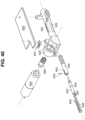
- FIG. 40 is an exploded view of a fluid metering subsystem according to a fifth exemplary embodiment of the invention.
- FIG. 41 is a cross sectional view of the assembled fluid metering system according to the embodiment of FIG. 40 .
- FIG. 42 A , FIG. 42 B , FIG. 43 A , FIG. 43 B , FIG. 44 A , FIG. 44 B , FIG. 45 A , FIG. 45 B , FIG. 46 A , FIG. 46 B , FIG. 47 A and FIG. 47 B depict stages of the pump cycle of the fluid metering system according to the embodiment of FIG. 40 .
- a drive piston and a floating piston are oriented axially in a pump housing and the relative position of the pistons defines a pump volume V .
- the “axial direction” means along the longitudinal axis of the pump housing and/or one of the pistons.
- the pump volume is alternately expanded, which creates negative pressure to draw fluid from a reservoir through a first aperture into the pump volume, and compressed, to deliver the fluid through a second aperture to a cannula line.
- the pump volume may be sized according to the dosage to be delivered by the pump, in a range of 0.1 ⁇ l to 50 ⁇ l, for example.
- the pump volume is about 5.0 ⁇ l, designed so that two complete pump cycles delivers a unit of insulin at the customary U.S. concentration.
- the discharge stroke empties the entire pump volume contents. It is also possible to increment the discharge stroke to provide for smaller dosage increments.
- FIG. 1 provides a schematic overview of a fluid delivery system 100 , comprising a reservoir 120 in fluid communication with metering subsystem 200 for drawing a precise amount of fluid from the reservoir, and a cannula mechanism 122 for delivering medication to the user 101 .
- the metering subsystem (the pump) is preferably lightweight and wearable.
- the cannula mechanism 122 may be connected to the infusion site by an infusion set comprising tubing and a patch, or alternatively a cannula insertion mechanism maybe incorporated into a housing within the metering subsystem 200 .
- the reservoir 120 is preferably flexible and is not engaged with a plunger and lead screw, as is the case with many prior art insulin pumps.
- the flexible reservoir does not have an internal actuator mechanism for delivering fluid, which permits the overall pump to have a smaller footprint and more compact design.
- the reservoir may be filled via a fill port 123 by syringe 121 , for example, or a prefilled reservoir or cartridge may be used.
- Microcontroller 10 is provided in the form of a printed circuit board (PCB) which interfaces with sensors and circuitry 11 , 12 , 13 , 14 , 15 , 17 and with actuators 16 and 18 , to control the pump and cannula.
- Power is provided by one or more batteries 19 in the housing.
- Audible feedback and visual display and user operable controls may be provided on the unit, operatively connected to the PCB, or on a remote programming unit, to set dosage, deploy the cannula, initiate infusion and deliver bolus dosages, as is known in the prior art.
- the components of the metering subsystem 200 are depicted in an exploded view in FIG. 2 and assembled in FIG. 3 .
- the metering subsystem 200 includes motor 224 and gear 226 for driving a positive displacement pump.
- the pump includes a tubular pump housing 228 , and a multi-segment piston aligned axially within the pump housing.
- a drive piston 232 and a floating piston 234 are axially oriented within the pump housing and coupled to each other.
- the drive piston 232 and the floating piston 234 each have a pair of radially disposed seals 231 , 233 and 235 , 237 frictionally engaged with an internal surface of the tubular pump housing 228 .
- seals 231 , 233 , 235 and 237 are radially positioned elastomeric O-rings.
- seals could be molded directly onto the pistons or alternative seal systems may be adapted to perform the same function, such as quad rings, or polytretrafluoroethylene (TEFLON®) or polyethylene lip seals.
- the components of the metering subsystem are made of a rigid medical grade plastic, such as acrylonitrile butadiene styrene (ABS), while liquid silicone rubber (LSR) with shore A hardness between 20 and 50 is used for the seals.
- LSR liquid silicone rubber
- the LSR seals may be molded directly onto the hard plastic substrates, in which case the substrate parts should be made of a plastic material with a higher softening temperature such as polyetherimide (PEI) or polysulfone (PS).
- PEI polyetherimide
- PS polysulfone
- the disclosure refers to a “floating piston” in the various embodiments. This term is used for convenience only. “Floating” in this context simply means that the element is not directly coupled to the motor, but rather has some independent movement as a result of the frictional engagement of the radial seals with the internal surface of the tubular pump housing.
- the term “piston” simply refers to the piston-like arrangement in the tubular pump housing, and is not meant to convey how liquid is compressed in the pump volume space. Likewise, a piston need not be moved to be translated with respect to another piston or element.
- pairs of seals 231 , 233 and 235 , 237 create fluid control valves actively shuttled between the reservoir port 241 and cannula port 242 at each end of the pump stroke to alternately block and open the ports to ensure that fluid flow is unidirectional (from the reservoir 120 to the patient 101 ) and that there is no possibility of flow from the patient to the reservoir.
- the piston assembly comprises drive rack 238 , a drive piston, 232 and a floating piston 234 which are coupled to each other.
- the piston segments are attached with a series of hooks, including a first hook 205 on a first end of the floating piston coupled to a second hook 204 on the end of the drive piston axially opposite the first end of the floating piston 234 .
- a gap between the first hook 205 and the second hook 204 permits defined axial movement of the floating piston 234 with respect to the drive piston 232 .
- a third hook 203 on the opposite end of the drive piston 232 is coupled to a fourth hook 201 on the drive rack.
- a gap between the third hook 203 and the fourth hook 201 permits defined axial movement between the drive rack 228 and the drive piston 232 which may be used to provide a stepwise increase in the load on the motor during the pump cycle, as described below.
- the pumping volume is located in the interface between drive piston 232 and floating piston 234 between seals 233 and 235 , and the pump volume space is defined by the relative positions of drive piston 232 and floating piston 234 .
- reservoir port 241 Prior to initiation of the intake stroke, reservoir port 241 is positioned between radial seals 233 and 235 on the respective coupled ends of the drive piston and floating piston, and the gap area between hooks 205 and 204 is open to reservoir port 241 .
- the cannula port 242 on the other hand is closed by drive piston 232 in the initial state.
- the initial state of the pump prior to initiation of the pump cycle is depicted in FIG. 6 A .
- the motor 224 is engaged to the gear 226 and the gear is engaged to a drive rack 238 to translate the floating piston 234 axially with respect to drive piston 232 .
- the engagement of L-shaped hook 201 on drive rack 238 with the L-shaped hook 203 on drive piston leaves a coupling gap 243 which allows the motor to start with a light load, closing the gap before engaging the drive piston 232 .
- the gap between hooks 204 and 205 on drive piston 232 and floating piston 234 allows the pump volume to expand and allows the cannula port 242 and reservoir port 241 to access the pump volume at different stages of the pump cycle.
- the tubular positive displacement pump provides a short tolerance loop for dose accuracy, dependent on the readily measurable dimensions of the tubular pump housing 228 inside diameter and the hook features of pistons 232 and 234 .
- the dosage is not directly calibrated to the turning of motor 224 , so that the pistons may over-travel within the pump housing without affecting dose accuracy.
- a DC gear motor 224 powered by a battery 19 is depicted in FIG. 3
- other motor systems may be adapted for use with the invention, such as a solenoid, nitinol (nickel-titanium alloy) wire motor, voice coil actuator motor, piezoelectric motor, and wax motor.
- FIG. 7 A and the corresponding cross sectional view of FIG. 7 B show metering system 200 during an intake stroke.
- the intake stroke is designed so that a stepwise increasing load is applied to the motor, which is advantageous to motor efficiency and battery life.
- the coupling gap 243 (shown in FIG. 6 B ) allows the motor to start under light load, minimizing start up currents which adversely affect battery life.
- drive rack 238 is translated axially to close the gap between drive rack 238 and drive piston 232 as a result of clockwise turning of gear 226 . When the gap between the drive rack and the piston is closed, drive rack 238 directly engages drive piston 232 .
- floating piston 234 In this stage of the intake stroke, floating piston 234 is stationary while the pump volume expands, drawing fluid through reservoir port 241 into the pump volume. During the intake stroke, friction between seals 235 , 237 on floating piston 234 and the internal diameter of pump housing 228 must be high enough to ensure that negative intake pressure acting on the face of floating piston 234 does not move this piston before the intake stroke is complete.
- FIG. 8 A and FIG. 8 B depict metering system 200 after the intake stroke, when the pump volume is fully expanded.
- the movement of drive rack 238 , drive piston 232 and floating piston 234 is depicted with arrows.
- the floating piston 234 begins to move under the urging of motor 224 and the continued clockwise rotation of gear 226 .
- Reservoir inlet 241 is blocked as seal 235 on floating piston 234 passes over the inlet orifice for reservoir port to change the valve state.
- the blocking and opening of the reservoir port and cannula port follows a specific sequence. During the valve change state after the intake stroke, the reservoir port is blocked first. This is followed by an intermediate state in which both ports are blocked.
- the system is designed to have an intermediate state to ensure that the two seals do not pass over the side holes at the same time.
- the sequenced valve transition minimizes the likelihood of backflow as the seal moves over the port when infusing at high back pressure.
- FIG. 9 A and FIG. 9 B show metering system 200 in its fully retracted state, with drive rack 238 fully retracted from tubular pump housing 228 and cannula port 242 opened to the expanded pump volume between seals 233 and 235 . In this position, reservoir port 241 is blocked by floating piston 234 .
- motor 224 and gear 226 rotate in the opposite direction (counterclockwise), noted by arrows, so that drive rack 238 pushes drive piston 232 toward the floating piston 234 , which initially remains stationary while pump volume V collapses and pushes fluid from the pump volume through cannula port 242 .
- friction between the seals on floating piston 234 and the internal surface of pump housing 228 must be high enough to ensure that positive pressure acting on the face of floating piston 234 does not move this piston before the discharge stroke is complete.
- the discharge stroke is designed so that a stepwise increasing load is applied to the motor.
- FIG. 11 A and FIG. 11 B depict metering system 200 after the discharge stroke and during the valve state change.
- the pump volume is fully collapsed, and the force of motor 224 acts to move floating piston 234 in the direction indicated by the arrows in FIG. 11 B .
- Cannula port 242 is first blocked, as the seal on drive piston 233 passes over the inlet aperture of cannula port 242 .
- Reservoir port 241 is aligned with the collapsed pump volume, returning the piston segments to the starting position as shown in FIG. 12 A and FIG. 12 B .
- the piston segments are independent, and are not coupled to each other.
- the position of the drive piston is fixed (referred to as the “fixed piston” in this embodiment), and the relative axial position of the piston segments is achieved by translating the pump housing.
- DC motor 324 and pinion gear 326 drive a pump housing 314 back and forth in a cradle 316 .
- the drive rack 328 is incorporated on the top of pump housing 314 .
- Fixed piston 332 is rigidly secured to the cradle 316 via a first keying rib 320 and does not move during the pumping cycle.
- Floating piston 334 translates back and forth relative to the fixed piston due to axial clearance between groove 330 on the floating piston and a second keying rib 322 on cradle 316 .
- the pump volume is formed between facing surfaces of fixed piston 332 and floating piston 334 .
- FIG. 13 A shows the assembly with motor 324 received in a housing 325 which, in the embodiment shown, is integral with the cradle 316 and located so that gear 326 is located about centrally to the housing.
- the relative displacement of the floating and fixed pistons 332 , 334 determines the pump stroke.
- the aperture of reservoir port 352 is aligned between floating piston 334 and the stationary drive piston 332 .
- FIG. 14 shows the starting position for the pump cycle according to the second alternative embodiment in cross section.
- the travel limit sensor 347 is engaged and the pistons approach each other.
- counterclockwise rotation of gear 326 (viewed down the shaft toward the motor) engages drive rack 328 and translates pump housing 314 in the direction of floating piston 334 .
- floating piston 334 moves with the pump housing 314 due to friction between the seals and the interior surface of the pump housing and a pump volume V forms between the facing ends of the floating piston and fixed piston 332 , 334 . Fluid is drawn from the reservoir through reservoir port 352 due to negative pressure created in the pump volume V .
- FIG. 18 shows the pump during the discharge stroke according to this embodiment of the invention.
- the motor shaft rotates in the opposite (clockwise) direction in the embodiment shown translating pump housing 314 and floating piston 334 in the direction of fixed piston 332 , as shown by the arrows in FIG. 18 .
- Pump volume V collapses, driving fluid down the cannula line through cannula port 351 .
- friction between seals on floating piston 334 and the internal diameter of pump housing 314 must be high enough to ensure that there is no relative motion between the floating piston 334 and the pump housing during this portion of the pump cycle.
- FIG. 19 the pump cycle is completed, the end of groove 330 on floating piston reaches the key stop 322 to prevent further movement.
- the travel sensor 347 is activated, and the device is at the starting position ready for another pump cycle.
- the pump volume is formed between a drive piston received within the bore of the floating piston (the floating piston in these embodiments is also referred to as a “spool.”)
- the drive piston is driven by a motor, via gear and a drive rack to expand and compress a pump volume, which in this case is formed within the bore of the spool.
- the seals on the spool are frictionally engaged with the interior of the pump housing. Positive and negative pressures in the pump volume space are maintained by a seal on the drive piston frictionally engaged with an internal surface of the bore.
- motor 424 is received in a housing 425 , which may be integral with a tubular pump housing 438 .
- pinion gear 426 engages a drive rack 428 which is coupled to a drive piston 432 .
- the coupling of drive rack 428 to drive piston 432 , as well as the engagement of drive piston 432 in spool 434 may take various forms.
- drive piston 432 remains inside the bore of spool 434 during the pump cycle, and drive rack 428 includes an axial extension 408 which couples to drive piston 432 using cooperating hooks 401 , 402 , which are also received in pump housing 438 .
- Drive piston 432 is coupled to spool 434 using a coupling pin 403 received in slot 405 in spool 434 and through a hole 404 in the drive piston.
- the axial length of slot 405 and the diameter of coupling pin 403 determine the freedom of movement of drive piston 432 inside the bore of spool 434 during the pump cycle.
- FIG. 24 A and the corresponding cross section of FIG. 24 B depict the starting position of the pump cycle.
- the axial extension 408 of drive rack 428 is fully extended into spool 434 and coupling pin 403 abuts the axial end of elongated slot 405 , defining the furthest extension of drive piston 432 into spool 434 .
- Seals 433 and 431 on the spool block cannula port 452 , leaving reservoir port 451 open to the middle segment of the spool.
- FIG. 25 A and the corresponding cross section of FIG. 25 B depict the intake stroke according to this embodiment of the invention.
- drive piston 432 is axially displaced within the floating piston bore 409 in the direction indicated by the arrow remaining entirely within bore 409 throughout the pump cycle, while floating piston 434 initially remains stationary due to frictional engagement of seals 431 , 433 , 435 , and 437 on floating piston 434 with the internal surface of the pump housing 438 .
- Fluid is drawn into the pump volume space V in bore 409 from the reservoir through reservoir port 451 and opening 407 in floating piston 434 .
- the intake stroke is designed so that a stepwise increasing load is applied to the motor, which is advantageous to motor efficiency and battery life.
- the coupling between hooks 401 and 402 on the drive rack and drive piston, respectively, allows the motor to start under light load, minimizing start up currents which adversely affect battery life.
- Drive rack 428 does not engage and begin to move drive piston 432 until the gap closes.
- Drive piston 432 has one sliding seal 406 in frictional engagement with the internal surface of bore 409 of floating piston 434 .
- a travel limit sensor 441 triggers the motor to change direction.
- travel limit sensor 441 may trigger when the limit of the drive rack travel is reached, or a more precise mechanism may be employed, such as an optical sensor and an encoder, which counts the teeth on gear 426 as the gear rotates.
- FIG. 27 A and FIG. 27 B depict the discharge stroke, depicted in FIG. 27 A and FIG. 27 B .
- motor 424 rotates counterclockwise (looking in a direction down the motor shaft toward the motor) and floating piston 434 is again initially stationary as a result of the frictional engagement of the seals.
- Drive piston 432 compresses pump volume space V to expel fluid through cannula port 452 .
- the pump volume V is fully collapsed and floating piston 434 begins to move in tubular pump housing 438 .
- the valve changes state and cannula port 452 is blocked as seal 435 passes over the aperture, after which reservoir port 451 opens to aperture 407 in floating piston 434 .
- FIG. 29 A and FIG. 29 B depict the final stages of the pump cycle, returning the piston assembly to the position in which the drive rack is fully extended at the completion of the pump cycle.
- FIGS. 30 through 40 B the drive rack and piston are combined into one driven piston 501 which remains entirely within the floating piston bore throughout the pump cycle.
- a window 504 is cut into the side of the floating piston 534 to allow gear 526 to engage driven piston 501 received inside the pump housing and move it axially. This arrangement permits a shorter axial length for pump housing 538 and a smaller overall footprint.
- pump housing 538 is shown formed with a housing 525 to receive the motor 524 and a support 502 for the pinion gear 526 , so that the gear can access the drive rack portion of driven piston 501 through opening 504 in the floating piston 534 .
- the pump cycle for the fourth embodiment is similar to the pump cycle for the previous embodiment.
- the combined drive rack/piston 501 is fully extended into the bore of the floating piston 534 , and the floating piston is at the far end of pump housing 538 in the direction away from gear 526 .
- Cannula port 552 and the reservoir port 551 are positioned on the side of the pump housing facing the motor, although this positioning is arbitrary.
- the combined drive rack/piston 501 is driven by gear 526 rotating in the clockwise direction to expand the pump volume space V in the bore of floating piston 534 , or spool as it is also called in this embodiment.
- FIG. 35 A and FIG. 35 B depict the position of the floating piston 534 after the intake stroke during the valve state change.
- motor 524 overcomes the frictional engagement of spool with the internal surface of tubular pump housing 538 and the spool is pulled by the action of the motor.
- Reservoir port 551 is initially blocked as seal passes over the aperture.
- expanded pump volume V in the bore of the spool 534 is aligned to cannula port 552 .
- the end of the intake stroke triggers a travel limit sensor 541 and motor 524 changes direction.
- FIG. 35 A and FIG. 35 B depict the position of the floating piston 534 after the intake stroke during the valve state change.
- the combined drive rack/piston component 501 compresses the pump volume V in the bore of the spool 534 expelling fluid from cannula port 552 to the infusion site.
- continued rotation of the gear 526 pushes the combined drive rack/piston and the spool 534 back to the starting position, as shown in FIG. 39 A and FIG. 39 B .
- the fifth alternative embodiment of the invention is a variation of the piston-and-spool configuration described in connection with the fourth embodiment.
- the floating piston (or “spool” as it also called in this embodiment) 634 is coupled to the drive piston 632 with a pin 603 received through an axially elongated slot 605 in the floating piston and through a hole 604 in the drive piston 632 .
- the pin travels in slots 601 and 602 in the tubular housing 638 .
- the slots 601 , 602 do not limit axial travel of the pistons and axial clearance is provided in slots 601 and 602 for the pin. These slots are provided for ease of assembly.
- the motion of pin 603 in slot 605 determines the stroke of the pump.
- the stroke of the drive piston depends upon the length of slot 605 and the diameter of pin 603 .
- the pump volume space in this embodiment is defined by an axial extension 608 received in the bore 609 of the spool.
- opening 610 in spool 634 is aligned with reservoir port 651 and the spool blocks cannula port 652 .
- the motor operating on drive rack 628 via gear 626 causes drive piston 632 to be axially displaced within the bore in spool 634 , thereby expanding the pump volume space so that fluid is drawn into the space as a result of negative pressure.
- Pressure is maintained in the pump volume space by frictional engagement of seal 616 on drive piston 632 on an internal surface of spool 634 .
- spool 634 does not move inside tubular housing 638 , as a result of frictional engagement of radially compressed seals 631 , 633 , 635 , and 637 with tubular housing 638 .
- drive piston 632 begins to pull spool 634 toward drive gear 626 via pin 603 bearing on the end of slot 605 .
- Movement of spool 634 changes the state of the valve in a manner similar to that described in connection with previous embodiments. Opening 610 in spool 634 passes from reservoir port 651 to cannula port 652 as shown in FIG. 43 A and FIG. 43 B .
- travel limit sensor 647 is triggered and the discharge stroke of FIG. 45 A and 45 B is initiated, pushing fluid out of cannula port 652 .
- drive piston 632 After completion of the discharge stroke, drive piston 632 begins to push spool 634 away from drive gear 626 via pin 603 bearing on the end of slot 605 . Movement of spool 634 shown in FIG. 46 A and 46 B changes the state of the valve. At the completion of the valve state change, the metering system has returned to the starting position of the pump cycle as shown in FIG. 47 A and FIG. 47 B .
Abstract
Description
Claims (19)
Priority Applications (2)
| Application Number | Priority Date | Filing Date | Title |
|---|---|---|---|
| US16/685,847 US11793929B2 (en) | 2014-04-18 | 2019-11-15 | Split piston metering pump |
| US18/479,386 US20240024568A1 (en) | 2014-04-18 | 2023-10-02 | Split piston metering pump |
Applications Claiming Priority (3)
| Application Number | Priority Date | Filing Date | Title |
|---|---|---|---|
| US14/256,365 US10004845B2 (en) | 2014-04-18 | 2014-04-18 | Split piston metering pump |
| US15/989,848 US10512719B2 (en) | 2014-04-18 | 2018-05-25 | Split piston metering pump |
| US16/685,847 US11793929B2 (en) | 2014-04-18 | 2019-11-15 | Split piston metering pump |
Related Parent Applications (1)
| Application Number | Title | Priority Date | Filing Date |
|---|---|---|---|
| US15/989,848 Division US10512719B2 (en) | 2014-04-18 | 2018-05-25 | Split piston metering pump |
Related Child Applications (1)
| Application Number | Title | Priority Date | Filing Date |
|---|---|---|---|
| US18/479,386 Division US20240024568A1 (en) | 2014-04-18 | 2023-10-02 | Split piston metering pump |
Publications (2)
| Publication Number | Publication Date |
|---|---|
| US20200078511A1 US20200078511A1 (en) | 2020-03-12 |
| US11793929B2 true US11793929B2 (en) | 2023-10-24 |
Family
ID=53002508
Family Applications (4)
| Application Number | Title | Priority Date | Filing Date |
|---|---|---|---|
| US14/256,365 Active 2036-11-25 US10004845B2 (en) | 2014-04-18 | 2014-04-18 | Split piston metering pump |
| US15/989,848 Active 2034-05-02 US10512719B2 (en) | 2014-04-18 | 2018-05-25 | Split piston metering pump |
| US16/685,847 Active 2036-10-28 US11793929B2 (en) | 2014-04-18 | 2019-11-15 | Split piston metering pump |
| US18/479,386 Pending US20240024568A1 (en) | 2014-04-18 | 2023-10-02 | Split piston metering pump |
Family Applications Before (2)
| Application Number | Title | Priority Date | Filing Date |
|---|---|---|---|
| US14/256,365 Active 2036-11-25 US10004845B2 (en) | 2014-04-18 | 2014-04-18 | Split piston metering pump |
| US15/989,848 Active 2034-05-02 US10512719B2 (en) | 2014-04-18 | 2018-05-25 | Split piston metering pump |
Family Applications After (1)
| Application Number | Title | Priority Date | Filing Date |
|---|---|---|---|
| US18/479,386 Pending US20240024568A1 (en) | 2014-04-18 | 2023-10-02 | Split piston metering pump |
Country Status (7)
| Country | Link |
|---|---|
| US (4) | US10004845B2 (en) |
| EP (3) | EP2992916B1 (en) |
| JP (2) | JP6649691B2 (en) |
| CN (1) | CN204995910U (en) |
| CA (2) | CA3201084A1 (en) |
| DK (1) | DK3597234T3 (en) |
| ES (2) | ES2867099T3 (en) |
Families Citing this family (32)
| Publication number | Priority date | Publication date | Assignee | Title |
|---|---|---|---|---|
| PL1762259T3 (en) | 2005-09-12 | 2011-03-31 | Unomedical As | Inserter for an infusion set with a first and second spring units |
| MX2012011085A (en) | 2010-03-30 | 2012-10-10 | Unomedical As | Medical device. |
| DE102010044189A1 (en) * | 2010-11-19 | 2012-05-24 | BSH Bosch und Siemens Hausgeräte GmbH | Aquiferous domestic appliance e.g. laundry treatment apparatus for washing and/or drying laundry, has controller to output procedural instructions addressed to user through output device |
| WO2012123274A1 (en) | 2011-03-14 | 2012-09-20 | Unomedical A/S | Inserter system with transport protection |
| CN103957962B (en) | 2011-10-05 | 2017-07-07 | 犹诺医药有限公司 | Insert for inserting multiple percutaneous parts simultaneously |
| EP2583715A1 (en) | 2011-10-19 | 2013-04-24 | Unomedical A/S | Infusion tube system and method for manufacture |
| EP4201327A1 (en) | 2012-03-30 | 2023-06-28 | Insulet Corporation | Fluid delivery device with transcutaneous access tool, insertion mechanism and blood glucose monitoring for use therewith |
| JP6714007B2 (en) * | 2015-02-02 | 2020-06-24 | サノフィ−アベンティス・ドイチュラント・ゲゼルシャフト・ミット・ベシュレンクテル・ハフツング | How to prime a medical pump |
| CN108778370B (en) | 2016-01-19 | 2021-10-08 | 优诺医疗有限公司 | Cannula and infusion device |
| EP3468639B1 (en) | 2016-06-08 | 2023-08-16 | SHL Medical AG | Device for dispensing a fluid |
| WO2018005915A1 (en) * | 2016-06-30 | 2018-01-04 | West Pharmaceutical Services, Inc. | Reusable, patient controlled syringe drive device |
| US10441723B2 (en) | 2016-08-14 | 2019-10-15 | Insulet Corporation | Variable fill drug delivery device |
| WO2018067645A1 (en) | 2016-10-07 | 2018-04-12 | Insulet Corporation | Multi-stage delivery system |
| US10780217B2 (en) | 2016-11-10 | 2020-09-22 | Insulet Corporation | Ratchet drive for on body delivery system |
| WO2018136699A1 (en) | 2017-01-19 | 2018-07-26 | Insulet Corporation | Cartridge hold-up volume reduction |
| EP3354303B1 (en) | 2017-01-31 | 2020-01-08 | Société Industrielle de Sonceboz S.A. | Drug delivery system |
| US10695485B2 (en) | 2017-03-07 | 2020-06-30 | Insulet Corporation | Very high volume user filled drug delivery device |
| EP3641855A4 (en) * | 2017-06-20 | 2021-01-06 | Zealand Pharma A/S | Time delay mechanism for a hydraulic drug delivery device |
| US10973978B2 (en) | 2017-08-03 | 2021-04-13 | Insulet Corporation | Fluid flow regulation arrangements for drug delivery devices |
| EP3662161A1 (en) | 2017-08-03 | 2020-06-10 | Insulet Corporation | Micro piston pump |
| US11786668B2 (en) | 2017-09-25 | 2023-10-17 | Insulet Corporation | Drug delivery devices, systems, and methods with force transfer elements |
| US10874803B2 (en) | 2018-05-31 | 2020-12-29 | Insulet Corporation | Drug cartridge with drive system |
| EP3801682A1 (en) * | 2018-06-06 | 2021-04-14 | Insulet Corporation | Linear shuttle pump for drug delivery |
| US11174852B2 (en) | 2018-07-20 | 2021-11-16 | Becton, Dickinson And Company | Reciprocating pump |
| CA3117989C (en) | 2018-11-28 | 2024-02-20 | Insulet Corporation | Drug delivery shuttle pump system and valve assembly |
| WO2020183866A1 (en) * | 2019-03-13 | 2020-09-17 | テルモ株式会社 | Medical fluid administration apparatus and cradle device |
| SG11202111673SA (en) | 2019-05-20 | 2021-11-29 | Unomedical As | Rotatable infusion device and methods thereof |
| US11369735B2 (en) | 2019-11-05 | 2022-06-28 | Insulet Corporation | Component positioning of a linear shuttle pump |
| JP2023512260A (en) * | 2020-01-31 | 2023-03-24 | ベクトン・ディキンソン・アンド・カンパニー | A pump that forms a pump chamber by expansion and contraction due to friction |
| CN112415224B (en) * | 2020-11-04 | 2022-11-15 | 深圳市讯美科技有限公司 | Infrared reflection type liquid dripping speed detector |
| FR3134727A1 (en) | 2022-04-26 | 2023-10-27 | Société Industrielle de Sonceboz S.A. | Improved injection system for transdermal drug delivery device |
| CN115671446B (en) * | 2022-11-02 | 2023-07-14 | 河北鸟巢科技有限公司 | Infusion apparatus, infusion tube assembly and infusion apparatus assembly |
Citations (213)
| Publication number | Priority date | Publication date | Assignee | Title |
|---|---|---|---|---|
| US3857382A (en) | 1972-10-27 | 1974-12-31 | Sinai Hospital Of Detroit | Piezoelectric heart assist apparatus |
| US3963380A (en) | 1975-01-06 | 1976-06-15 | Thomas Jr Lyell J | Micro pump powered by piezoelectric disk benders |
| GB1508665A (en) | 1974-06-27 | 1978-04-26 | Brundbjerg N | Piston pump |
| US4204538A (en) | 1978-06-07 | 1980-05-27 | Imed Corporation | Cassette for intravenous controller |
| US4465478A (en) | 1982-10-14 | 1984-08-14 | Collagen Corporation | Syringe force amplification device |
| US4685902A (en) | 1983-08-24 | 1987-08-11 | Becton, Dickinson And Company | Disposable reservoir cassette |
| US4723947A (en) | 1986-04-09 | 1988-02-09 | Pacesetter Infusion, Ltd. | Insulin compatible infusion set |
| US4734092A (en) | 1987-02-18 | 1988-03-29 | Ivac Corporation | Ambulatory drug delivery device |
| US4755173A (en) | 1986-02-25 | 1988-07-05 | Pacesetter Infusion, Ltd. | Soft cannula subcutaneous injection set |
| US5002528A (en) | 1989-12-15 | 1991-03-26 | Aubrey Palestrant | Percutaneous irrigation and drainage system |
| US5176662A (en) | 1990-08-23 | 1993-01-05 | Minimed Technologies, Ltd. | Subcutaneous injection set with improved cannula mounting arrangement |
| US5207666A (en) | 1991-08-30 | 1993-05-04 | Infusaid, Inc. | Passive shuttle metering device for implantable drug delivery system |
| US5226899A (en) | 1990-03-26 | 1993-07-13 | Becton, Dickinson And Company | Catheter tubing of controlled in vivo softening |
| US5257980A (en) | 1993-04-05 | 1993-11-02 | Minimed Technologies, Ltd. | Subcutaneous injection set with crimp-free soft cannula |
| US5279585A (en) | 1992-02-04 | 1994-01-18 | Becton, Dickinson And Company | Medication delivery pen having improved dose delivery features |
| US5453099A (en) | 1990-03-26 | 1995-09-26 | Becton, Dickinson And Company | Catheter tubing of controlled in vivo softening |
| JPH0872266A (en) | 1994-09-09 | 1996-03-19 | Brother Ind Ltd | Pump and pump with driving device |
| US5522803A (en) | 1993-03-09 | 1996-06-04 | Pharma Plast International A/S | Infusion set for an intermittent or continuous administration of a therapeutical substance |
| US5536249A (en) | 1994-03-09 | 1996-07-16 | Visionary Medical Products, Inc. | Pen-type injector with a microprocessor and blood characteristic monitor |
| US5545143A (en) | 1993-01-21 | 1996-08-13 | T. S. I. Medical | Device for subcutaneous medication delivery |
| US5545152A (en) | 1994-10-28 | 1996-08-13 | Minimed Inc. | Quick-connect coupling for a medication infusion system |
| US5549575A (en) | 1994-09-13 | 1996-08-27 | Becton Dickinson And Company | Cartridge retainer assembly for medication delivery pen |
| US5569214A (en) | 1994-09-20 | 1996-10-29 | Becton Dickinson And Company | Dose setting knob adapter for medication delivery pen |
| US5582598A (en) | 1994-09-19 | 1996-12-10 | Becton Dickinson And Company | Medication delivery pen with variable increment dose scale |
| US5674204A (en) | 1995-09-19 | 1997-10-07 | Becton Dickinson And Company | Medication delivery pen cap actuated dose delivery clutch |
| US5807075A (en) * | 1993-11-23 | 1998-09-15 | Sarcos, Inc. | Disposable ambulatory microprocessor controlled volumetric pump |
| US5820602A (en) | 1995-09-08 | 1998-10-13 | Visionary Medical Products, Inc. | Pen-type injector drive mechanism |
| US5851197A (en) | 1997-02-05 | 1998-12-22 | Minimed Inc. | Injector for a subcutaneous infusion set |
| US5858005A (en) | 1997-08-27 | 1999-01-12 | Science Incorporated | Subcutaneous infusion set with dynamic needle |
| US5858001A (en) | 1995-12-11 | 1999-01-12 | Elan Medical Technologies Limited | Cartridge-based drug delivery device |
| WO1999034212A1 (en) | 1997-12-31 | 1999-07-08 | Duke University | Biosensor |
| US5921966A (en) | 1997-08-11 | 1999-07-13 | Becton Dickinson And Company | Medication delivery pen having an improved clutch assembly |
| US5944700A (en) | 1997-09-26 | 1999-08-31 | Becton, Dickinson And Company | Adjustable injection length pen needle |
| US5957895A (en) | 1998-02-20 | 1999-09-28 | Becton Dickinson And Company | Low-profile automatic injection device with self-emptying reservoir |
| US5968011A (en) | 1997-06-20 | 1999-10-19 | Maersk Medical A/S | Subcutaneous injection set |
| US5980506A (en) | 1998-03-20 | 1999-11-09 | Mathiasen; Orla | Subcutaneous infusion device |
| EP0980687A1 (en) | 1998-08-20 | 2000-02-23 | Sooil Development Co., Ltd. | Portable automatic syringe driver |
| US6056718A (en) | 1998-03-04 | 2000-05-02 | Minimed Inc. | Medication infusion set |
| US6068615A (en) | 1994-07-22 | 2000-05-30 | Health Hero Network, Inc. | Inductance-based dose measurement in syringes |
| US6086575A (en) | 1998-03-20 | 2000-07-11 | Maersk Medical A/S | Subcutaneous infusion device |
| US6093172A (en) | 1997-02-05 | 2000-07-25 | Minimed Inc. | Injector for a subcutaneous insertion set |
| US6096010A (en) | 1998-02-20 | 2000-08-01 | Becton, Dickinson And Company | Repeat-dose medication delivery pen |
| US6110149A (en) | 1996-09-13 | 2000-08-29 | Novo Nordisk A/S | Syringe |
| US6110148A (en) | 1994-07-22 | 2000-08-29 | Health Hero Network, Inc. | Capacitance-based dose measurements in syringes |
| US6123690A (en) | 1998-03-20 | 2000-09-26 | Maersk Medical A/S | Subcutaneous infusion device |
| US6132400A (en) | 1994-09-27 | 2000-10-17 | Waldenburg; Ottfried | Dual-chamber syringe and methods |
| US6175752B1 (en) | 1998-04-30 | 2001-01-16 | Therasense, Inc. | Analyte monitoring device and methods of use |
| US6221053B1 (en) | 1998-02-20 | 2001-04-24 | Becton, Dickinson And Company | Multi-featured medication delivery pen |
| US6248095B1 (en) | 1998-02-23 | 2001-06-19 | Becton, Dickinson And Company | Low-cost medication delivery pen |
| US6254586B1 (en) | 1998-09-25 | 2001-07-03 | Minimed Inc. | Method and kit for supplying a fluid to a subcutaneous placement site |
| US6272364B1 (en) | 1998-05-13 | 2001-08-07 | Cygnus, Inc. | Method and device for predicting physiological values |
| US6275717B1 (en) | 1997-06-16 | 2001-08-14 | Elan Corporation, Plc | Device and method of calibrating and testing a sensor for in vivo measurement of an analyte |
| US6277099B1 (en) | 1999-08-06 | 2001-08-21 | Becton, Dickinson And Company | Medication delivery pen |
| US6293925B1 (en) | 1997-12-31 | 2001-09-25 | Minimed Inc. | Insertion device for an insertion set and method of using the same |
| US6302866B1 (en) | 1998-05-14 | 2001-10-16 | Disetronic Licensing Ag | Catheter head for subcutaneous administration of an substance |
| US6355021B1 (en) | 1998-07-14 | 2002-03-12 | Maersk Medical A/S | Medical puncturing device |
| US20020040208A1 (en) | 2000-10-04 | 2002-04-04 | Flaherty J. Christopher | Data collection assembly for patient infusion system |
| US6391005B1 (en) | 1998-03-30 | 2002-05-21 | Agilent Technologies, Inc. | Apparatus and method for penetration with shaft having a sensor for sensing penetration depth |
| US6485461B1 (en) | 2000-04-04 | 2002-11-26 | Insulet, Inc. | Disposable infusion device |
| JP2003509133A (en) | 1999-09-16 | 2003-03-11 | ノボ ノルディスク アクティーゼルスカブ | Dose setting limiter |
| US20030055380A1 (en) | 2001-09-19 | 2003-03-20 | Flaherty J. Christopher | Plunger for patient infusion device |
| US6537242B1 (en) | 2000-06-06 | 2003-03-25 | Becton, Dickinson And Company | Method and apparatus for enhancing penetration of a member for the intradermal sampling or administration of a substance |
| US6544212B2 (en) | 2001-07-31 | 2003-04-08 | Roche Diagnostics Corporation | Diabetes management system |
| US6551276B1 (en) | 1998-08-18 | 2003-04-22 | Medtronic Minimed, Inc. | External infusion device with remote programming bolus estimator and/or vibration alarm capabilities |
| US6558351B1 (en) | 1999-06-03 | 2003-05-06 | Medtronic Minimed, Inc. | Closed loop system for controlling insulin infusion |
| US6576430B1 (en) | 2000-11-20 | 2003-06-10 | Becton, Dickinson And Company | Detection of ligands by refractive surface methods |
| US20030109829A1 (en) | 2001-09-28 | 2003-06-12 | Mogensen Lasse Wesseltoft | Injector device for placing a subcutaneous infusion set |
| US6579267B2 (en) | 2001-01-05 | 2003-06-17 | Applied Diabetes Research, Inc. | Pivoting joint infusion assembly |
| US6589229B1 (en) | 2000-07-31 | 2003-07-08 | Becton, Dickinson And Company | Wearable, self-contained drug infusion device |
| US6607509B2 (en) | 1997-12-31 | 2003-08-19 | Medtronic Minimed, Inc. | Insertion device for an insertion set and method of using the same |
| WO2003074121A1 (en) | 2002-03-01 | 2003-09-12 | Insulet Corporation | Flow condition sensor for infusion device |
| US6656159B2 (en) | 2002-04-23 | 2003-12-02 | Insulet Corporation | Dispenser for patient infusion device |
| US6656158B2 (en) | 2002-04-23 | 2003-12-02 | Insulet Corporation | Dispenser for patient infusion device |
| US6669669B2 (en) | 2001-10-12 | 2003-12-30 | Insulet Corporation | Laminated patient infusion device |
| US20040002682A1 (en) | 1997-02-05 | 2004-01-01 | Medtronic Minimed, Inc. | Insertion device for an insertion set and method of using the same |
| US20040010207A1 (en) | 2002-07-15 | 2004-01-15 | Flaherty J. Christopher | Self-contained, automatic transcutaneous physiologic sensing system |
| JP2004503303A (en) | 2000-06-16 | 2004-02-05 | ノボ ノルディスク アクティーゼルスカブ | Injection device with gearbox |
| US6692472B2 (en) | 2000-05-04 | 2004-02-17 | Novo Nordisk A/S | Injection device, a preassembled dose setting and injection mechanism for an injection device, and a method of assembling an injection device |
| US6699218B2 (en) | 2000-11-09 | 2004-03-02 | Insulet Corporation | Transcutaneous delivery means |
| US6706159B2 (en) | 2000-03-02 | 2004-03-16 | Diabetes Diagnostics | Combined lancet and electrochemical analyte-testing apparatus |
| US20040059316A1 (en) | 2002-07-31 | 2004-03-25 | Smedegaard Jorgen K. | Medical delivery device |
| US6723072B2 (en) | 2002-06-06 | 2004-04-20 | Insulet Corporation | Plunger assembly for patient infusion device |
| WO2004032994A2 (en) | 2002-10-09 | 2004-04-22 | Therasense, Inc. | Fluid delivery device, system and method |
| US20040078028A1 (en) | 2001-11-09 | 2004-04-22 | Flaherty J. Christopher | Plunger assembly for patient infusion device |
| US6740059B2 (en) | 2000-09-08 | 2004-05-25 | Insulet Corporation | Devices, systems and methods for patient infusion |
| US6749587B2 (en) | 2001-02-22 | 2004-06-15 | Insulet Corporation | Modular infusion device and method |
| US6749560B1 (en) | 1999-10-26 | 2004-06-15 | Circon Corporation | Endoscope shaft with slotted tube |
| US20040116866A1 (en) | 2002-12-17 | 2004-06-17 | William Gorman | Skin attachment apparatus and method for patient infusion device |
| US6768425B2 (en) | 2000-12-21 | 2004-07-27 | Insulet Corporation | Medical apparatus remote control and method |
| US20040153032A1 (en) | 2002-04-23 | 2004-08-05 | Garribotto John T. | Dispenser for patient infusion device |
| US20040162521A1 (en) | 2002-10-07 | 2004-08-19 | Henrik Bengtsson | Needle device comprising a plurality of needles |
| US20040204687A1 (en) | 2001-09-27 | 2004-10-14 | Mogensen Lasse Wesseltoft | Injector device for placing a subcutaneous infusion set |
| US20040220551A1 (en) | 2003-04-30 | 2004-11-04 | Flaherty J. Christopher | Low profile components for patient infusion device |
| US6830558B2 (en) | 2002-03-01 | 2004-12-14 | Insulet Corporation | Flow condition sensor assembly for patient infusion device |
| US20040260233A1 (en) | 2000-09-08 | 2004-12-23 | Garibotto John T. | Data collection assembly for patient infusion system |
| US20050022274A1 (en) | 2003-04-18 | 2005-01-27 | Robert Campbell | User interface for infusion pump remote controller and method of using the same |
| US6852104B2 (en) | 2002-02-28 | 2005-02-08 | Smiths Medical Md, Inc. | Programmable insulin pump |
| US20050065760A1 (en) | 2003-09-23 | 2005-03-24 | Robert Murtfeldt | Method for advising patients concerning doses of insulin |
| US20050101932A1 (en) | 2003-11-10 | 2005-05-12 | Steve Cote | Subcutaneous infusion device and device for insertion of a cannula of an infusion device and method |
| US20050101933A1 (en) | 2003-11-10 | 2005-05-12 | James Marrs | Subcutaneous infusion device and method |
| US20050113761A1 (en) | 2003-11-10 | 2005-05-26 | Mark Faust | Subcutaneous infusion device and method including release feature for adhesive portion |
| JP2005520646A (en) | 2002-03-18 | 2005-07-14 | イーライ・リリー・アンド・カンパニー | Drug dispensing device with gear set giving mechanical advantages |
| US20050182366A1 (en) | 2003-04-18 | 2005-08-18 | Insulet Corporation | Method For Visual Output Verification |
| US6932794B2 (en) | 2003-04-03 | 2005-08-23 | Becton, Dickinson And Company | Medication delivery pen |
| US6936032B1 (en) | 1999-08-05 | 2005-08-30 | Becton, Dickinson And Company | Medication delivery pen |
| US20050197625A1 (en) | 2002-08-30 | 2005-09-08 | Ulrich Haueter | Device for the dosed discharging of a liquid agent and infusion pump |
| US6945961B2 (en) | 2002-07-10 | 2005-09-20 | Novo Nordisk A/S | Injection device |
| US6949084B2 (en) | 1998-05-14 | 2005-09-27 | Disetronic Licensing Ag | Catheter head for subcutaneous administration of an active substance |
| US20050215982A1 (en) | 2003-04-30 | 2005-09-29 | Luis Malave | RF medical device |
| US20050238507A1 (en) | 2002-04-23 | 2005-10-27 | Insulet Corporation | Fluid delivery device |
| US6960192B1 (en) | 2002-04-23 | 2005-11-01 | Insulet Corporation | Transcutaneous fluid delivery system |
| US6960162B2 (en) | 2002-06-13 | 2005-11-01 | Usgi Medical Inc. | Shape lockable apparatus and method for advancing an instrument through unsupported anatomy |
| US20050245799A1 (en) | 2004-05-03 | 2005-11-03 | Dexcom, Inc. | Implantable analyte sensor |
| US20050273076A1 (en) | 2004-06-07 | 2005-12-08 | C.R. Bard, Inc. | Subcutaneous infusion devices |
| US6977180B2 (en) | 2001-08-28 | 2005-12-20 | Duke University | Biosensor |
| US20050283144A1 (en) | 2004-03-31 | 2005-12-22 | Terumo Kabushiki Kaisha | Energy irradiating medical equipment, energy irradiating medical apparatus and irradiation method |
| US20060041229A1 (en) | 2002-07-16 | 2006-02-23 | Insulet Corporation | Flow restriction system and method for patient infusion device |
| US7004928B2 (en) | 2002-02-08 | 2006-02-28 | Rosedale Medical, Inc. | Autonomous, ambulatory analyte monitor or drug delivery device |
| US7052251B2 (en) | 2002-04-22 | 2006-05-30 | Medtronic Minimed, Inc. | Shape memory alloy wire driven positive displacement micropump with pulsatile output |
| US20060122577A1 (en) | 2001-09-26 | 2006-06-08 | Poulsen Jens U | Modular drug delivery system |
| US20060129090A1 (en) | 2004-12-03 | 2006-06-15 | Medtronic Minimed, Inc. | Multi-position infusion set device and process |
| US7064103B2 (en) | 2002-01-04 | 2006-06-20 | Becton, Dickinson And Company | Binding protein as biosensors |
| US20060135913A1 (en) | 2003-05-08 | 2006-06-22 | Novo Nordisk A/S | Pivotable needle unit |
| US20060142698A1 (en) | 2003-05-08 | 2006-06-29 | Novo Nordisk A/S | Internal needle inserter |
| US7070580B2 (en) | 2003-04-01 | 2006-07-04 | Unomedical A/S | Infusion device and an adhesive sheet material and a release liner |
| US7083597B2 (en) | 2001-01-05 | 2006-08-01 | Applied Diabetes Research, Inc. | Pivoting joint infusion system with seal |
| US20060178633A1 (en) | 2005-02-03 | 2006-08-10 | Insulet Corporation | Chassis for fluid delivery device |
| US20060200073A1 (en) | 2003-07-08 | 2006-09-07 | Novo Nordisk A/S | Portable drug delivery device having an encapsulated needle |
| US7104972B2 (en) | 2002-07-10 | 2006-09-12 | Novo Nordisk A/S | Injection device with a dose setting limiter |
| US7128727B2 (en) | 2002-09-30 | 2006-10-31 | Flaherty J Christopher | Components and methods for patient infusion device |
| US20060253086A1 (en) | 2005-05-06 | 2006-11-09 | Medtronic Minimed, Inc. | Medical needles for damping motion |
| US20060263839A1 (en) | 2005-05-17 | 2006-11-23 | Isense Corporation | Combined drug delivery and analyte sensor apparatus |
| US20060264835A1 (en) | 2003-10-21 | 2006-11-23 | Novo Nordisk A/S | Medical skin mountable device |
| JP2006526467A (en) | 2003-05-30 | 2006-11-24 | イーライ リリー アンド カンパニー | Multiple chamber type dosing device |
| US7144384B2 (en) | 2002-09-30 | 2006-12-05 | Insulet Corporation | Dispenser components and methods for patient infusion device |
| US20070016149A1 (en) | 2004-01-16 | 2007-01-18 | Marcel Hunn | Injection Needle |
| US7169132B2 (en) | 2002-10-01 | 2007-01-30 | Becton, Dickinson And Company | Medication delivery pen |
| US20070049865A1 (en) | 2003-08-01 | 2007-03-01 | Novo Nordisk A/S | Retraction means for transcutaneous device |
| US20070073559A1 (en) | 2000-11-13 | 2007-03-29 | Peter Stangel | Clinical care utilization management system |
| US20070088244A1 (en) | 2005-10-18 | 2007-04-19 | Biocardia, Inc. | Bio-interventional therapeutic treatments for cardiovascular diseases |
| US20070088271A1 (en) | 2005-10-18 | 2007-04-19 | Richards Cynthia C | Medication device |
| WO2007051139A2 (en) | 2005-10-27 | 2007-05-03 | Insulet Corporation | Diabetes management systems and methods |
| US7214207B2 (en) | 2002-03-08 | 2007-05-08 | Applied Diabetes Research, Inc. | Low profile, pivotal connection infusion assembly |
| US7220248B2 (en) | 2002-12-23 | 2007-05-22 | M2 Medical A/S | Flexible piston rod |
| US7250037B2 (en) | 2002-07-22 | 2007-07-31 | Becton, Dickinson And Company | Patch-like infusion device |
| US20070191702A1 (en) | 2006-02-15 | 2007-08-16 | Medingo Ltd. | Systems and methods for sensing analyte and dispensing therapeutic fluid |
| WO2007119149A2 (en) | 2006-04-13 | 2007-10-25 | Arcotronics Technologies S.R.L. | Displacement dosing device and corresponding movement apparatus |
| US20070261677A1 (en) | 2006-05-12 | 2007-11-15 | Bennion Robert F | Paired-piston linear engine |
| US7303543B1 (en) | 2004-12-03 | 2007-12-04 | Medtronic Minimed, Inc. | Medication infusion set |
| US7310544B2 (en) | 2004-07-13 | 2007-12-18 | Dexcom, Inc. | Methods and systems for inserting a transcutaneous analyte sensor |
| US20080004515A1 (en) | 2006-06-30 | 2008-01-03 | Abbott Diabetes Care, Inc. | Integrated Analyte Sensor and Infusion Device and Methods Therefor |
| US7329239B2 (en) | 1997-02-05 | 2008-02-12 | Medtronic Minimed, Inc. | Insertion device for an insertion set and method of using the same |
| US20080051711A1 (en) | 2006-08-23 | 2008-02-28 | Medtronic Minimed, Inc. | Infusion medium delivery device and method with drive device for driving plunger in reservoir |
| US20080051730A1 (en) | 2006-08-23 | 2008-02-28 | Medtronic Minimed, Inc. | Infusion medium delivery system, device and method with needle inserter and needle inserter device and method |
| US20080051698A1 (en) | 2006-08-23 | 2008-02-28 | Medtronic Minimed, Inc. | Infusion medium delivery device and method with compressible or curved reservoir or conduit |
| US20080051716A1 (en) | 2006-08-23 | 2008-02-28 | Medtronic Minimed, Inc. | Infusion pumps and methods and delivery devices and methods with same |
| US20080051710A1 (en) | 2006-08-23 | 2008-02-28 | Medtronic Minimed, Inc. | Systems and methods allowing for reservoir filling and infusion medium delivery |
| US20080051765A1 (en) | 2006-08-23 | 2008-02-28 | Medtronic Minimed, Inc. | Systems and methods allowing for reservoir filling and infusion medium delivery |
| US20080051727A1 (en) | 2006-08-23 | 2008-02-28 | Medtronic Minimed, Inc. | Infusion medium delivery device and method with drive device for driving plunger in reservoir |
| US7354420B2 (en) | 1999-06-03 | 2008-04-08 | Medtronic Minimed, Inc. | Closed loop system for controlling insulin infusion |
| WO2008040812A1 (en) | 2006-10-06 | 2008-04-10 | Sonion Roskilde A/S | Tissue handling system with reduced operator exposure |
| US20080086111A1 (en) | 2006-10-09 | 2008-04-10 | Medrad, Inc. | Fluid delivery systems and volume metering in cell delivery |
| US20080097327A1 (en) | 2006-08-23 | 2008-04-24 | Medtronic Minimed, Inc. | Systems and methods allowing for reservoir filling and infusion medium delivery |
| US20080097328A1 (en) | 2006-08-23 | 2008-04-24 | Medtronic Minimed, Inc. | Systems and methods allowing for reservoir filling and infusion medium delivery |
| US20080097326A1 (en) | 2006-08-23 | 2008-04-24 | Medtronic Minimed, Inc. | Infusion medium delivery device and method with drive device for driving plunger in reservoir |
| US20080097321A1 (en) | 2006-08-23 | 2008-04-24 | Medtronic Minimed, Inc. | Systems and methods allowing for reservoir filling and infusion medium delivery |
| US20080114305A1 (en) | 2004-08-10 | 2008-05-15 | Gerondale Scott J | Botox® Injector |
| US20080119707A1 (en) | 2006-10-23 | 2008-05-22 | Gary Ashley Stafford | Flexible patch for fluid delivery and monitoring body analytes |
| US20080116647A1 (en) | 2006-10-18 | 2008-05-22 | Insulet Corporation | Environmental seal for fluid delivery device |
| US20080132842A1 (en) | 2002-06-06 | 2008-06-05 | Flaherty J Christopher | Plunger assembly for patient infusion device |
| US20080147041A1 (en) | 2005-02-28 | 2008-06-19 | Novo Nordisk A/S | Device for Providing a Change in a Drug Delivery Rate |
| US20080160492A1 (en) | 2006-08-08 | 2008-07-03 | Insulet Corporation | Interactive training system and method |
| WO2008086349A1 (en) | 2007-01-10 | 2008-07-17 | Acist Medical Systems, Inc. | Volumetric pump |
| US20080194924A1 (en) | 2005-02-22 | 2008-08-14 | Admetsys Corporation | Balanced Physiological Monitoring and Treatment System |
| US20080215006A1 (en) | 2004-09-22 | 2008-09-04 | Novo Nordisk A/S | Medical Device with Transcutaneous Cannula Device |
| US20080261255A1 (en) | 2003-05-09 | 2008-10-23 | Leah Tolosa | Proteins, Sensors, and Methods of Characterizing Analytes Using the Same |
| US20080269680A1 (en) | 2007-04-30 | 2008-10-30 | Medtronic Minimed, Inc. | Systems and methods for reservoir filling |
| US20080264261A1 (en) | 2007-04-30 | 2008-10-30 | Medtronic Minimed, Inc. | Systems and methods allowing for reservoir air bubble management |
| US20080269713A1 (en) | 2007-04-30 | 2008-10-30 | Medtronic Minimed, Inc. | Automated filling systems and methods |
| WO2008141337A1 (en) | 2007-05-16 | 2008-11-20 | Smiths Medical Asd, Inc. | Pump module for use in a medical fluid dispensing system |
| US20080294028A1 (en) | 1997-01-10 | 2008-11-27 | Health Hero Network | Disease simulation system and method |
| US20080306434A1 (en) | 2007-06-08 | 2008-12-11 | Dexcom, Inc. | Integrated medicament delivery device for use with continuous analyte sensor |
| US20080312608A1 (en) | 2005-06-20 | 2008-12-18 | Novo Nordisk A/S | Cannula With Ductile Portion |
| US20090005728A1 (en) | 2007-06-27 | 2009-01-01 | Roche Diagnostics Operations, Inc. | Therapy delivery system having an open architecture and a method thereof |
| US20090005724A1 (en) | 2005-03-29 | 2009-01-01 | Medizinishe Universitat Graz | Device and Method for Delivery of a Physiologically Active Substance Depending on a Measured Physiological Parameter |
| US20090012472A1 (en) | 2004-09-22 | 2009-01-08 | Novo Nordisk A/S | Medical Device with Cannula Inserter |
| WO2009004627A2 (en) | 2007-07-02 | 2009-01-08 | Medingo Ltd. | A device for drug delivery |
| EP2019206A1 (en) | 2002-09-27 | 2009-01-28 | Novo Nordisk A/S | Membrane pump with stretchable pump membrane |
| WO2009021052A1 (en) | 2007-08-06 | 2009-02-12 | University Of Kentucky Research Foundation | Polypeptides, systems, and methods useful for detecting glucose |
| US20090048563A1 (en) | 2004-12-06 | 2009-02-19 | Novo Nordisk A/S | Ventilated Skin Mountable Device |
| US7496392B2 (en) | 2003-11-26 | 2009-02-24 | Becton, Dickinson And Company | Fiber optic device for sensing analytes |
| US20090062778A1 (en) | 2006-03-13 | 2009-03-05 | Novo Nordisk A/S | Medical System Comprising Dual-Purpose Communication Means |
| US20090062767A1 (en) | 2007-08-29 | 2009-03-05 | Medtronic Minimed, Inc. | Combined sensor and infusion set using separated sites |
| US20090076453A1 (en) | 2005-12-23 | 2009-03-19 | Signe Thorning Mejlhede | Device for Administration |
| US20090149743A1 (en) | 2005-11-21 | 2009-06-11 | Acist Medical Systems, Inc. | Medical Fluid Injection System |
| US20090204077A1 (en) | 2008-02-13 | 2009-08-13 | Hasted Soren B | Moulded Connection Between Cannula and Delivery Part |
| US7722595B2 (en) | 2002-05-06 | 2010-05-25 | Becton, Dickinson And Company | Method and device for controlling drug pharmacokinetics |
| US7726955B2 (en) | 2003-10-27 | 2010-06-01 | Sensile Pat Ag | Pump system |
| US20100218586A1 (en) | 2009-02-27 | 2010-09-02 | Rosinko Michael J | Methods and devices for determination of flow reservoir volume |
| US7857131B2 (en) | 2003-08-12 | 2010-12-28 | Becton, Dickinson And Company | Patch-like infusion device |
| US20110021990A1 (en) * | 2009-07-23 | 2011-01-27 | Thierry Navarro | Micropump and method for manufacturing thereof |
| US20110054400A1 (en) | 2009-09-02 | 2011-03-03 | Medtronic Minimed, Inc. | Insertion device systems and methods |
| EP2357454A1 (en) | 2010-02-17 | 2011-08-17 | COMAS S.p.A. | Volumetric doser of food products and method for dosing a food product |
| US8021334B2 (en) | 2004-05-30 | 2011-09-20 | Nilimedix Ltd. | Drug delivery device and method |
| US20110230838A1 (en) | 2008-06-26 | 2011-09-22 | Calibra Medical, Inc. | Disposable infusion device with redundant valved safety |
| US20120118138A1 (en) | 2009-07-23 | 2012-05-17 | Swissinnov Product Sarl | Fluid delivery system comprising a fluid pumping device and a drive system |
| WO2012069308A1 (en) | 2010-11-25 | 2012-05-31 | F. Hoffmann-La Roche Ag | Infusion pump having dosing unit with safety valve |
| WO2012084033A1 (en) | 2010-12-22 | 2012-06-28 | Henri Lescher | Micropump assembly |
| WO2012126744A1 (en) | 2011-03-18 | 2012-09-27 | Gambro Lundia Ab | Infusion system and method of integrity testing and leak detection |
| US8282366B2 (en) | 2005-12-28 | 2012-10-09 | Sensile Pat Ag | Micropump |
| WO2013190428A1 (en) | 2012-06-22 | 2013-12-27 | Koninklijke Philips N.V. | Spring-driven pump for dispensing discrete bursts of liquid |
| WO2014090745A1 (en) | 2012-12-10 | 2014-06-19 | Sanofi-Aventis Deutschland Gmbh | Medical pump and method of operating the same |
| WO2014207532A1 (en) | 2013-06-25 | 2014-12-31 | Swissinnov Product Sarl | Positive-displacement micropump |
-
2014
- 2014-04-18 US US14/256,365 patent/US10004845B2/en active Active
-
2015
- 2015-03-24 CA CA3201084A patent/CA3201084A1/en active Pending
- 2015-03-24 CA CA2885687A patent/CA2885687C/en active Active
- 2015-04-01 JP JP2015075106A patent/JP6649691B2/en active Active
- 2015-04-15 ES ES19187067T patent/ES2867099T3/en active Active
- 2015-04-15 DK DK19187067.4T patent/DK3597234T3/en active
- 2015-04-15 EP EP15163622.2A patent/EP2992916B1/en active Active
- 2015-04-15 ES ES15163622T patent/ES2773349T3/en active Active
- 2015-04-15 EP EP19187067.4A patent/EP3597234B1/en active Active
- 2015-04-15 EP EP20209705.1A patent/EP3804785A1/en active Pending
- 2015-04-16 CN CN201520228068.5U patent/CN204995910U/en active Active
-
2018
- 2018-05-25 US US15/989,848 patent/US10512719B2/en active Active
-
2019
- 2019-11-15 US US16/685,847 patent/US11793929B2/en active Active
-
2020
- 2020-01-17 JP JP2020005959A patent/JP6802399B2/en active Active
-
2023
- 2023-10-02 US US18/479,386 patent/US20240024568A1/en active Pending
Patent Citations (273)
| Publication number | Priority date | Publication date | Assignee | Title |
|---|---|---|---|---|
| US3857382A (en) | 1972-10-27 | 1974-12-31 | Sinai Hospital Of Detroit | Piezoelectric heart assist apparatus |
| GB1508665A (en) | 1974-06-27 | 1978-04-26 | Brundbjerg N | Piston pump |
| US3963380A (en) | 1975-01-06 | 1976-06-15 | Thomas Jr Lyell J | Micro pump powered by piezoelectric disk benders |
| US4204538A (en) | 1978-06-07 | 1980-05-27 | Imed Corporation | Cassette for intravenous controller |
| US4465478A (en) | 1982-10-14 | 1984-08-14 | Collagen Corporation | Syringe force amplification device |
| US4685902A (en) | 1983-08-24 | 1987-08-11 | Becton, Dickinson And Company | Disposable reservoir cassette |
| US4755173A (en) | 1986-02-25 | 1988-07-05 | Pacesetter Infusion, Ltd. | Soft cannula subcutaneous injection set |
| US4723947A (en) | 1986-04-09 | 1988-02-09 | Pacesetter Infusion, Ltd. | Insulin compatible infusion set |
| US4734092A (en) | 1987-02-18 | 1988-03-29 | Ivac Corporation | Ambulatory drug delivery device |
| US5002528A (en) | 1989-12-15 | 1991-03-26 | Aubrey Palestrant | Percutaneous irrigation and drainage system |
| US5226899A (en) | 1990-03-26 | 1993-07-13 | Becton, Dickinson And Company | Catheter tubing of controlled in vivo softening |
| US5453099A (en) | 1990-03-26 | 1995-09-26 | Becton, Dickinson And Company | Catheter tubing of controlled in vivo softening |
| US5176662A (en) | 1990-08-23 | 1993-01-05 | Minimed Technologies, Ltd. | Subcutaneous injection set with improved cannula mounting arrangement |
| US5207666A (en) | 1991-08-30 | 1993-05-04 | Infusaid, Inc. | Passive shuttle metering device for implantable drug delivery system |
| US5279585A (en) | 1992-02-04 | 1994-01-18 | Becton, Dickinson And Company | Medication delivery pen having improved dose delivery features |
| US5279586A (en) | 1992-02-04 | 1994-01-18 | Becton, Dickinson And Company | Reusable medication delivery pen |
| US6017328A (en) | 1993-01-21 | 2000-01-25 | Magnolia Medical, Llc | Device for subcutaneous medication delivery |
| US5545143A (en) | 1993-01-21 | 1996-08-13 | T. S. I. Medical | Device for subcutaneous medication delivery |
| US5522803A (en) | 1993-03-09 | 1996-06-04 | Pharma Plast International A/S | Infusion set for an intermittent or continuous administration of a therapeutical substance |
| US5257980A (en) | 1993-04-05 | 1993-11-02 | Minimed Technologies, Ltd. | Subcutaneous injection set with crimp-free soft cannula |
| US5807075A (en) * | 1993-11-23 | 1998-09-15 | Sarcos, Inc. | Disposable ambulatory microprocessor controlled volumetric pump |
| US5536249A (en) | 1994-03-09 | 1996-07-16 | Visionary Medical Products, Inc. | Pen-type injector with a microprocessor and blood characteristic monitor |
| US5925021A (en) | 1994-03-09 | 1999-07-20 | Visionary Medical Products, Inc. | Medication delivery device with a microprocessor and characteristic monitor |
| US5593390A (en) | 1994-03-09 | 1997-01-14 | Visionary Medical Products, Inc. | Medication delivery device with a microprocessor and characteristic monitor |
| US5728074A (en) | 1994-03-09 | 1998-03-17 | Visionary Medical Products, Inc. | Pen-type injector with a microprocessor and blood characteristic monitor |
| US6110148A (en) | 1994-07-22 | 2000-08-29 | Health Hero Network, Inc. | Capacitance-based dose measurements in syringes |
| US6068615A (en) | 1994-07-22 | 2000-05-30 | Health Hero Network, Inc. | Inductance-based dose measurement in syringes |
| US6352523B1 (en) | 1994-07-22 | 2002-03-05 | Health Hero Network, Inc. | Capacitance-based dose measurements in syringes |
| JPH0872266A (en) | 1994-09-09 | 1996-03-19 | Brother Ind Ltd | Pump and pump with driving device |
| US5549575A (en) | 1994-09-13 | 1996-08-27 | Becton Dickinson And Company | Cartridge retainer assembly for medication delivery pen |
| US5582598A (en) | 1994-09-19 | 1996-12-10 | Becton Dickinson And Company | Medication delivery pen with variable increment dose scale |
| US5569214A (en) | 1994-09-20 | 1996-10-29 | Becton Dickinson And Company | Dose setting knob adapter for medication delivery pen |
| US6132400A (en) | 1994-09-27 | 2000-10-17 | Waldenburg; Ottfried | Dual-chamber syringe and methods |
| US5545152A (en) | 1994-10-28 | 1996-08-13 | Minimed Inc. | Quick-connect coupling for a medication infusion system |
| US5820602A (en) | 1995-09-08 | 1998-10-13 | Visionary Medical Products, Inc. | Pen-type injector drive mechanism |
| US5674204A (en) | 1995-09-19 | 1997-10-07 | Becton Dickinson And Company | Medication delivery pen cap actuated dose delivery clutch |
| US5858001A (en) | 1995-12-11 | 1999-01-12 | Elan Medical Technologies Limited | Cartridge-based drug delivery device |
| US6110149A (en) | 1996-09-13 | 2000-08-29 | Novo Nordisk A/S | Syringe |
| US20080294028A1 (en) | 1997-01-10 | 2008-11-27 | Health Hero Network | Disease simulation system and method |
| US7329239B2 (en) | 1997-02-05 | 2008-02-12 | Medtronic Minimed, Inc. | Insertion device for an insertion set and method of using the same |
| US6093172A (en) | 1997-02-05 | 2000-07-25 | Minimed Inc. | Injector for a subcutaneous insertion set |
| US7207974B2 (en) | 1997-02-05 | 2007-04-24 | Medtronic Minimed, Inc. | Insertion device for an insertion set and method of using the same |
| US6997907B2 (en) | 1997-02-05 | 2006-02-14 | Medtronic Minimed, Inc. | Insertion device for an insertion set and method of using the same |
| US20040002682A1 (en) | 1997-02-05 | 2004-01-01 | Medtronic Minimed, Inc. | Insertion device for an insertion set and method of using the same |
| US7318816B2 (en) | 1997-02-05 | 2008-01-15 | Medtronic Minimed, Inc. | Insertion device for an insertion set and method of using the same |
| US5851197A (en) | 1997-02-05 | 1998-12-22 | Minimed Inc. | Injector for a subcutaneous infusion set |
| US6275717B1 (en) | 1997-06-16 | 2001-08-14 | Elan Corporation, Plc | Device and method of calibrating and testing a sensor for in vivo measurement of an analyte |
| US5968011A (en) | 1997-06-20 | 1999-10-19 | Maersk Medical A/S | Subcutaneous injection set |
| US5957896A (en) | 1997-08-11 | 1999-09-28 | Becton, Dickinson And Company | Medication delivery pen |
| US5921966A (en) | 1997-08-11 | 1999-07-13 | Becton Dickinson And Company | Medication delivery pen having an improved clutch assembly |
| US5858005A (en) | 1997-08-27 | 1999-01-12 | Science Incorporated | Subcutaneous infusion set with dynamic needle |
| US5944700A (en) | 1997-09-26 | 1999-08-31 | Becton, Dickinson And Company | Adjustable injection length pen needle |
| US6277627B1 (en) | 1997-12-31 | 2001-08-21 | Duke University | Biosensor |
| US20030199823A1 (en) | 1997-12-31 | 2003-10-23 | Minimed Inc. | Insertion device for an insertion set and method of using the same |
| WO1999034212A1 (en) | 1997-12-31 | 1999-07-08 | Duke University | Biosensor |
| EP1044374B1 (en) | 1997-12-31 | 2008-10-08 | Duke University | Glucose biosensor |
| US6521446B2 (en) | 1997-12-31 | 2003-02-18 | Duke University | Biosensor |
| US6607509B2 (en) | 1997-12-31 | 2003-08-19 | Medtronic Minimed, Inc. | Insertion device for an insertion set and method of using the same |
| US6293925B1 (en) | 1997-12-31 | 2001-09-25 | Minimed Inc. | Insertion device for an insertion set and method of using the same |
| US5957895A (en) | 1998-02-20 | 1999-09-28 | Becton Dickinson And Company | Low-profile automatic injection device with self-emptying reservoir |
| US6221053B1 (en) | 1998-02-20 | 2001-04-24 | Becton, Dickinson And Company | Multi-featured medication delivery pen |
| US6074369A (en) | 1998-02-20 | 2000-06-13 | Becton, Dickinson And Company | Low-profile automatic injection device with self-emptying reservoir |
| US6096010A (en) | 1998-02-20 | 2000-08-01 | Becton, Dickinson And Company | Repeat-dose medication delivery pen |
| US6248095B1 (en) | 1998-02-23 | 2001-06-19 | Becton, Dickinson And Company | Low-cost medication delivery pen |
| US6520938B1 (en) | 1998-03-04 | 2003-02-18 | Medtronic Minimed, Inc. | Medication infusion set |
| US6056718A (en) | 1998-03-04 | 2000-05-02 | Minimed Inc. | Medication infusion set |
| US6123690A (en) | 1998-03-20 | 2000-09-26 | Maersk Medical A/S | Subcutaneous infusion device |
| US5980506A (en) | 1998-03-20 | 1999-11-09 | Mathiasen; Orla | Subcutaneous infusion device |
| US6086575A (en) | 1998-03-20 | 2000-07-11 | Maersk Medical A/S | Subcutaneous infusion device |
| US6391005B1 (en) | 1998-03-30 | 2002-05-21 | Agilent Technologies, Inc. | Apparatus and method for penetration with shaft having a sensor for sensing penetration depth |
| US6565509B1 (en) | 1998-04-30 | 2003-05-20 | Therasense, Inc. | Analyte monitoring device and methods of use |
| US6175752B1 (en) | 1998-04-30 | 2001-01-16 | Therasense, Inc. | Analyte monitoring device and methods of use |
| US6272364B1 (en) | 1998-05-13 | 2001-08-07 | Cygnus, Inc. | Method and device for predicting physiological values |
| US6546269B1 (en) | 1998-05-13 | 2003-04-08 | Cygnus, Inc. | Method and device for predicting physiological values |
| US6949084B2 (en) | 1998-05-14 | 2005-09-27 | Disetronic Licensing Ag | Catheter head for subcutaneous administration of an active substance |
| US6302866B1 (en) | 1998-05-14 | 2001-10-16 | Disetronic Licensing Ag | Catheter head for subcutaneous administration of an substance |
| US6840922B2 (en) | 1998-07-14 | 2005-01-11 | Unomedical A/S | Medical puncturing device |
| US20050090784A1 (en) | 1998-07-14 | 2005-04-28 | Maersk Medical A/S | Medical puncturing device |
| US6355021B1 (en) | 1998-07-14 | 2002-03-12 | Maersk Medical A/S | Medical puncturing device |
| US6551276B1 (en) | 1998-08-18 | 2003-04-22 | Medtronic Minimed, Inc. | External infusion device with remote programming bolus estimator and/or vibration alarm capabilities |
| US7109878B2 (en) | 1998-08-18 | 2006-09-19 | Medtronic Minimed, Inc. | External infusion device with remote programming, bolus estimator and/or vibration alarm capabilities |
| EP0980687A1 (en) | 1998-08-20 | 2000-02-23 | Sooil Development Co., Ltd. | Portable automatic syringe driver |
| US6254586B1 (en) | 1998-09-25 | 2001-07-03 | Minimed Inc. | Method and kit for supplying a fluid to a subcutaneous placement site |
| US6558351B1 (en) | 1999-06-03 | 2003-05-06 | Medtronic Minimed, Inc. | Closed loop system for controlling insulin infusion |
| US7354420B2 (en) | 1999-06-03 | 2008-04-08 | Medtronic Minimed, Inc. | Closed loop system for controlling insulin infusion |
| US6936032B1 (en) | 1999-08-05 | 2005-08-30 | Becton, Dickinson And Company | Medication delivery pen |
| US6277099B1 (en) | 1999-08-06 | 2001-08-21 | Becton, Dickinson And Company | Medication delivery pen |
| JP2003509133A (en) | 1999-09-16 | 2003-03-11 | ノボ ノルディスク アクティーゼルスカブ | Dose setting limiter |
| US6582404B1 (en) | 1999-09-16 | 2003-06-24 | Nna/S | Dose setting limiter |
| US6749560B1 (en) | 1999-10-26 | 2004-06-15 | Circon Corporation | Endoscope shaft with slotted tube |
| US6706159B2 (en) | 2000-03-02 | 2004-03-16 | Diabetes Diagnostics | Combined lancet and electrochemical analyte-testing apparatus |
| US6485461B1 (en) | 2000-04-04 | 2002-11-26 | Insulet, Inc. | Disposable infusion device |
| US6692472B2 (en) | 2000-05-04 | 2004-02-17 | Novo Nordisk A/S | Injection device, a preassembled dose setting and injection mechanism for an injection device, and a method of assembling an injection device |
| US6537242B1 (en) | 2000-06-06 | 2003-03-25 | Becton, Dickinson And Company | Method and apparatus for enhancing penetration of a member for the intradermal sampling or administration of a substance |
| JP2004503303A (en) | 2000-06-16 | 2004-02-05 | ノボ ノルディスク アクティーゼルスカブ | Injection device with gearbox |
| US6589229B1 (en) | 2000-07-31 | 2003-07-08 | Becton, Dickinson And Company | Wearable, self-contained drug infusion device |
| US7137964B2 (en) | 2000-09-08 | 2006-11-21 | Insulet Corporation | Devices, systems and methods for patient infusion |
| US20040260233A1 (en) | 2000-09-08 | 2004-12-23 | Garibotto John T. | Data collection assembly for patient infusion system |
| US6740059B2 (en) | 2000-09-08 | 2004-05-25 | Insulet Corporation | Devices, systems and methods for patient infusion |
| US7029455B2 (en) | 2000-09-08 | 2006-04-18 | Insulet Corporation | Devices, systems and methods for patient infusion |
| US20050171512A1 (en) | 2000-09-08 | 2005-08-04 | Insulet Corporation | Devices, systems and methods for patient infusion |
| US20020040208A1 (en) | 2000-10-04 | 2002-04-04 | Flaherty J. Christopher | Data collection assembly for patient infusion system |
| JP2004524869A (en) | 2000-10-04 | 2004-08-19 | インシュレット コーポレイション | Data collection assembly for patient infusion system |
| US6699218B2 (en) | 2000-11-09 | 2004-03-02 | Insulet Corporation | Transcutaneous delivery means |
| US20070073559A1 (en) | 2000-11-13 | 2007-03-29 | Peter Stangel | Clinical care utilization management system |
| US6576430B1 (en) | 2000-11-20 | 2003-06-10 | Becton, Dickinson And Company | Detection of ligands by refractive surface methods |
| US20040235446A1 (en) | 2000-12-21 | 2004-11-25 | Flaherty J. Christopher | Medical apparatus remote control and method |
| US6768425B2 (en) | 2000-12-21 | 2004-07-27 | Insulet Corporation | Medical apparatus remote control and method |
| US20030176852A1 (en) | 2001-01-05 | 2003-09-18 | Lynch George R | Low profile pivoting joint infusion assembly |
| US7083597B2 (en) | 2001-01-05 | 2006-08-01 | Applied Diabetes Research, Inc. | Pivoting joint infusion system with seal |
| US6579267B2 (en) | 2001-01-05 | 2003-06-17 | Applied Diabetes Research, Inc. | Pivoting joint infusion assembly |
| US6749587B2 (en) | 2001-02-22 | 2004-06-15 | Insulet Corporation | Modular infusion device and method |
| US20040204673A1 (en) | 2001-02-22 | 2004-10-14 | Flaherty J. Christopher | Modular infusion device and method |
| US6544212B2 (en) | 2001-07-31 | 2003-04-08 | Roche Diagnostics Corporation | Diabetes management system |
| US6977180B2 (en) | 2001-08-28 | 2005-12-20 | Duke University | Biosensor |
| US20040092878A1 (en) | 2001-09-19 | 2004-05-13 | Flaherty J. Christopher | Plunger for patient infusion device |
| US20030055380A1 (en) | 2001-09-19 | 2003-03-20 | Flaherty J. Christopher | Plunger for patient infusion device |
| US20060122577A1 (en) | 2001-09-26 | 2006-06-08 | Poulsen Jens U | Modular drug delivery system |
| US20040204687A1 (en) | 2001-09-27 | 2004-10-14 | Mogensen Lasse Wesseltoft | Injector device for placing a subcutaneous infusion set |
| US6830562B2 (en) | 2001-09-27 | 2004-12-14 | Unomedical A/S | Injector device for placing a subcutaneous infusion set |
| US20050043687A1 (en) | 2001-09-27 | 2005-02-24 | Mogensen Lasse Wesseltoft | Injector device for placing a subcutaneous infusion set |
| US20050124936A1 (en) | 2001-09-27 | 2005-06-09 | Unomedical A/S | Injector device for placing a subcutaneous infusion set |
| US20030109829A1 (en) | 2001-09-28 | 2003-06-12 | Mogensen Lasse Wesseltoft | Injector device for placing a subcutaneous infusion set |
| US20050021005A1 (en) | 2001-10-12 | 2005-01-27 | Flaherty J. Christopher | Laminated patient infusion device |
| US6669669B2 (en) | 2001-10-12 | 2003-12-30 | Insulet Corporation | Laminated patient infusion device |
| US20040078028A1 (en) | 2001-11-09 | 2004-04-22 | Flaherty J. Christopher | Plunger assembly for patient infusion device |
| US20040092865A1 (en) | 2001-11-09 | 2004-05-13 | J. Christopher Flaherty | Transcutaneous delivery means |
| US7064103B2 (en) | 2002-01-04 | 2006-06-20 | Becton, Dickinson And Company | Binding protein as biosensors |
| US7004928B2 (en) | 2002-02-08 | 2006-02-28 | Rosedale Medical, Inc. | Autonomous, ambulatory analyte monitor or drug delivery device |
| US6852104B2 (en) | 2002-02-28 | 2005-02-08 | Smiths Medical Md, Inc. | Programmable insulin pump |
| US6830558B2 (en) | 2002-03-01 | 2004-12-14 | Insulet Corporation | Flow condition sensor assembly for patient infusion device |
| US6692457B2 (en) | 2002-03-01 | 2004-02-17 | Insulet Corporation | Flow condition sensor assembly for patient infusion device |
| WO2003074121A1 (en) | 2002-03-01 | 2003-09-12 | Insulet Corporation | Flow condition sensor for infusion device |
| US20040127844A1 (en) | 2002-03-01 | 2004-07-01 | Flaherty J. Christopher | Flow condition sensor assembly for patient infusion device |
| US7214207B2 (en) | 2002-03-08 | 2007-05-08 | Applied Diabetes Research, Inc. | Low profile, pivotal connection infusion assembly |
| JP2005520646A (en) | 2002-03-18 | 2005-07-14 | イーライ・リリー・アンド・カンパニー | Drug dispensing device with gear set giving mechanical advantages |
| US7226278B2 (en) | 2002-04-22 | 2007-06-05 | Medtronic Minimed, Inc. | Shape memory alloy wire driven positive displacement micropump with pulsatile output |
| US7052251B2 (en) | 2002-04-22 | 2006-05-30 | Medtronic Minimed, Inc. | Shape memory alloy wire driven positive displacement micropump with pulsatile output |
| US6656158B2 (en) | 2002-04-23 | 2003-12-02 | Insulet Corporation | Dispenser for patient infusion device |
| US7303549B2 (en) | 2002-04-23 | 2007-12-04 | Insulet Corporation | Transcutaneous fluid delivery system |
| US20050238507A1 (en) | 2002-04-23 | 2005-10-27 | Insulet Corporation | Fluid delivery device |
| US6960192B1 (en) | 2002-04-23 | 2005-11-01 | Insulet Corporation | Transcutaneous fluid delivery system |
| US6656159B2 (en) | 2002-04-23 | 2003-12-02 | Insulet Corporation | Dispenser for patient infusion device |
| US20040153032A1 (en) | 2002-04-23 | 2004-08-05 | Garribotto John T. | Dispenser for patient infusion device |
| US7722595B2 (en) | 2002-05-06 | 2010-05-25 | Becton, Dickinson And Company | Method and device for controlling drug pharmacokinetics |
| US6723072B2 (en) | 2002-06-06 | 2004-04-20 | Insulet Corporation | Plunger assembly for patient infusion device |
| US20080132842A1 (en) | 2002-06-06 | 2008-06-05 | Flaherty J Christopher | Plunger assembly for patient infusion device |
| US6960162B2 (en) | 2002-06-13 | 2005-11-01 | Usgi Medical Inc. | Shape lockable apparatus and method for advancing an instrument through unsupported anatomy |
| US6945961B2 (en) | 2002-07-10 | 2005-09-20 | Novo Nordisk A/S | Injection device |
| US7104972B2 (en) | 2002-07-10 | 2006-09-12 | Novo Nordisk A/S | Injection device with a dose setting limiter |
| US20040010207A1 (en) | 2002-07-15 | 2004-01-15 | Flaherty J. Christopher | Self-contained, automatic transcutaneous physiologic sensing system |
| US7018360B2 (en) | 2002-07-16 | 2006-03-28 | Insulet Corporation | Flow restriction system and method for patient infusion device |
| US20060041229A1 (en) | 2002-07-16 | 2006-02-23 | Insulet Corporation | Flow restriction system and method for patient infusion device |
| US7250037B2 (en) | 2002-07-22 | 2007-07-31 | Becton, Dickinson And Company | Patch-like infusion device |
| US7678079B2 (en) | 2002-07-22 | 2010-03-16 | Becton, Dickinson And Company | Patch-like infusion device |
| US20040059316A1 (en) | 2002-07-31 | 2004-03-25 | Smedegaard Jorgen K. | Medical delivery device |
| US20050197625A1 (en) | 2002-08-30 | 2005-09-08 | Ulrich Haueter | Device for the dosed discharging of a liquid agent and infusion pump |
| EP2019206A1 (en) | 2002-09-27 | 2009-01-28 | Novo Nordisk A/S | Membrane pump with stretchable pump membrane |
| US7128727B2 (en) | 2002-09-30 | 2006-10-31 | Flaherty J Christopher | Components and methods for patient infusion device |
| US7144384B2 (en) | 2002-09-30 | 2006-12-05 | Insulet Corporation | Dispenser components and methods for patient infusion device |
| US20070073229A1 (en) | 2002-09-30 | 2007-03-29 | William Gorman | Dispenser Components And Methods For Patient Infusion Device |
| US20060282290A1 (en) | 2002-09-30 | 2006-12-14 | Insulet Corporation | Components and Methods For Patient Infusion Device |
| US7169132B2 (en) | 2002-10-01 | 2007-01-30 | Becton, Dickinson And Company | Medication delivery pen |
| US20040162521A1 (en) | 2002-10-07 | 2004-08-19 | Henrik Bengtsson | Needle device comprising a plurality of needles |
| WO2004032994A2 (en) | 2002-10-09 | 2004-04-22 | Therasense, Inc. | Fluid delivery device, system and method |
| US20040116866A1 (en) | 2002-12-17 | 2004-06-17 | William Gorman | Skin attachment apparatus and method for patient infusion device |
| US7220248B2 (en) | 2002-12-23 | 2007-05-22 | M2 Medical A/S | Flexible piston rod |
| US7070580B2 (en) | 2003-04-01 | 2006-07-04 | Unomedical A/S | Infusion device and an adhesive sheet material and a release liner |
| US7018364B2 (en) | 2003-04-03 | 2006-03-28 | Becton, Dickinson And Company | Medication delivery pen |
| US6932794B2 (en) | 2003-04-03 | 2005-08-23 | Becton, Dickinson And Company | Medication delivery pen |
| US20050182366A1 (en) | 2003-04-18 | 2005-08-18 | Insulet Corporation | Method For Visual Output Verification |
| US20050022274A1 (en) | 2003-04-18 | 2005-01-27 | Robert Campbell | User interface for infusion pump remote controller and method of using the same |
| US20070118405A1 (en) | 2003-04-18 | 2007-05-24 | Insulet Corporation | User Interface For Infusion Pump Remote Controller And Method Of Using The Same |
| US20050215982A1 (en) | 2003-04-30 | 2005-09-29 | Luis Malave | RF medical device |
| US20060074381A1 (en) | 2003-04-30 | 2006-04-06 | Luis Malave | Medical device initialization method & system |
| US20040220551A1 (en) | 2003-04-30 | 2004-11-04 | Flaherty J. Christopher | Low profile components for patient infusion device |
| US20050222645A1 (en) | 2003-04-30 | 2005-10-06 | Luis Malave | Microchip-based medical device |
| US20060142698A1 (en) | 2003-05-08 | 2006-06-29 | Novo Nordisk A/S | Internal needle inserter |
| US20060135913A1 (en) | 2003-05-08 | 2006-06-22 | Novo Nordisk A/S | Pivotable needle unit |
| US20080261255A1 (en) | 2003-05-09 | 2008-10-23 | Leah Tolosa | Proteins, Sensors, and Methods of Characterizing Analytes Using the Same |
| JP2006526467A (en) | 2003-05-30 | 2006-11-24 | イーライ リリー アンド カンパニー | Multiple chamber type dosing device |
| US20070060894A1 (en) | 2003-05-30 | 2007-03-15 | He Dai | Multiple chamber medication dispensing apparatus |
| US20060200073A1 (en) | 2003-07-08 | 2006-09-07 | Novo Nordisk A/S | Portable drug delivery device having an encapsulated needle |
| US20070049865A1 (en) | 2003-08-01 | 2007-03-01 | Novo Nordisk A/S | Retraction means for transcutaneous device |
| US7857131B2 (en) | 2003-08-12 | 2010-12-28 | Becton, Dickinson And Company | Patch-like infusion device |
| US20050065760A1 (en) | 2003-09-23 | 2005-03-24 | Robert Murtfeldt | Method for advising patients concerning doses of insulin |
| US20060264835A1 (en) | 2003-10-21 | 2006-11-23 | Novo Nordisk A/S | Medical skin mountable device |
| US20070021733A1 (en) | 2003-10-21 | 2007-01-25 | Novo Nordisk A/S | Internal fluid connector |
| US7726955B2 (en) | 2003-10-27 | 2010-06-01 | Sensile Pat Ag | Pump system |
| US20050101933A1 (en) | 2003-11-10 | 2005-05-12 | James Marrs | Subcutaneous infusion device and method |
| US20050113761A1 (en) | 2003-11-10 | 2005-05-26 | Mark Faust | Subcutaneous infusion device and method including release feature for adhesive portion |
| US20050101932A1 (en) | 2003-11-10 | 2005-05-12 | Steve Cote | Subcutaneous infusion device and device for insertion of a cannula of an infusion device and method |
| US7496392B2 (en) | 2003-11-26 | 2009-02-24 | Becton, Dickinson And Company | Fiber optic device for sensing analytes |
| US20070016149A1 (en) | 2004-01-16 | 2007-01-18 | Marcel Hunn | Injection Needle |
| US20050283144A1 (en) | 2004-03-31 | 2005-12-22 | Terumo Kabushiki Kaisha | Energy irradiating medical equipment, energy irradiating medical apparatus and irradiation method |
| US20050245799A1 (en) | 2004-05-03 | 2005-11-03 | Dexcom, Inc. | Implantable analyte sensor |
| US8021334B2 (en) | 2004-05-30 | 2011-09-20 | Nilimedix Ltd. | Drug delivery device and method |
| US20050273076A1 (en) | 2004-06-07 | 2005-12-08 | C.R. Bard, Inc. | Subcutaneous infusion devices |
| US7310544B2 (en) | 2004-07-13 | 2007-12-18 | Dexcom, Inc. | Methods and systems for inserting a transcutaneous analyte sensor |
| US20080114305A1 (en) | 2004-08-10 | 2008-05-15 | Gerondale Scott J | Botox® Injector |
| US20080215006A1 (en) | 2004-09-22 | 2008-09-04 | Novo Nordisk A/S | Medical Device with Transcutaneous Cannula Device |
| US20090012472A1 (en) | 2004-09-22 | 2009-01-08 | Novo Nordisk A/S | Medical Device with Cannula Inserter |
| US20060129090A1 (en) | 2004-12-03 | 2006-06-15 | Medtronic Minimed, Inc. | Multi-position infusion set device and process |
| US7303543B1 (en) | 2004-12-03 | 2007-12-04 | Medtronic Minimed, Inc. | Medication infusion set |
| US20090048563A1 (en) | 2004-12-06 | 2009-02-19 | Novo Nordisk A/S | Ventilated Skin Mountable Device |
| US20060178633A1 (en) | 2005-02-03 | 2006-08-10 | Insulet Corporation | Chassis for fluid delivery device |
| US20080194924A1 (en) | 2005-02-22 | 2008-08-14 | Admetsys Corporation | Balanced Physiological Monitoring and Treatment System |
| US20080147041A1 (en) | 2005-02-28 | 2008-06-19 | Novo Nordisk A/S | Device for Providing a Change in a Drug Delivery Rate |
| US20090005724A1 (en) | 2005-03-29 | 2009-01-01 | Medizinishe Universitat Graz | Device and Method for Delivery of a Physiologically Active Substance Depending on a Measured Physiological Parameter |
| US20060253086A1 (en) | 2005-05-06 | 2006-11-09 | Medtronic Minimed, Inc. | Medical needles for damping motion |
| US20060263839A1 (en) | 2005-05-17 | 2006-11-23 | Isense Corporation | Combined drug delivery and analyte sensor apparatus |
| US20080312608A1 (en) | 2005-06-20 | 2008-12-18 | Novo Nordisk A/S | Cannula With Ductile Portion |
| US20070088244A1 (en) | 2005-10-18 | 2007-04-19 | Biocardia, Inc. | Bio-interventional therapeutic treatments for cardiovascular diseases |
| US20070088271A1 (en) | 2005-10-18 | 2007-04-19 | Richards Cynthia C | Medication device |
| WO2007051139A2 (en) | 2005-10-27 | 2007-05-03 | Insulet Corporation | Diabetes management systems and methods |
| US20090149743A1 (en) | 2005-11-21 | 2009-06-11 | Acist Medical Systems, Inc. | Medical Fluid Injection System |
| US20090221971A1 (en) | 2005-12-23 | 2009-09-03 | Signe Thorning Mejlhede | Injection device |
| US20090076453A1 (en) | 2005-12-23 | 2009-03-19 | Signe Thorning Mejlhede | Device for Administration |
| US8282366B2 (en) | 2005-12-28 | 2012-10-09 | Sensile Pat Ag | Micropump |
| US20070191702A1 (en) | 2006-02-15 | 2007-08-16 | Medingo Ltd. | Systems and methods for sensing analyte and dispensing therapeutic fluid |
| US20090062778A1 (en) | 2006-03-13 | 2009-03-05 | Novo Nordisk A/S | Medical System Comprising Dual-Purpose Communication Means |
| WO2007119149A2 (en) | 2006-04-13 | 2007-10-25 | Arcotronics Technologies S.R.L. | Displacement dosing device and corresponding movement apparatus |
| US20070261677A1 (en) | 2006-05-12 | 2007-11-15 | Bennion Robert F | Paired-piston linear engine |
| US20080004515A1 (en) | 2006-06-30 | 2008-01-03 | Abbott Diabetes Care, Inc. | Integrated Analyte Sensor and Infusion Device and Methods Therefor |
| US20080160492A1 (en) | 2006-08-08 | 2008-07-03 | Insulet Corporation | Interactive training system and method |
| US20080051727A1 (en) | 2006-08-23 | 2008-02-28 | Medtronic Minimed, Inc. | Infusion medium delivery device and method with drive device for driving plunger in reservoir |
| US20080051711A1 (en) | 2006-08-23 | 2008-02-28 | Medtronic Minimed, Inc. | Infusion medium delivery device and method with drive device for driving plunger in reservoir |
| US20080051730A1 (en) | 2006-08-23 | 2008-02-28 | Medtronic Minimed, Inc. | Infusion medium delivery system, device and method with needle inserter and needle inserter device and method |
| US20080051698A1 (en) | 2006-08-23 | 2008-02-28 | Medtronic Minimed, Inc. | Infusion medium delivery device and method with compressible or curved reservoir or conduit |
| US20080097381A1 (en) | 2006-08-23 | 2008-04-24 | Medtronic Minimed, Inc. | Infusion medium delivery device and method with drive device for driving plunger in reservoir |
| US20080097321A1 (en) | 2006-08-23 | 2008-04-24 | Medtronic Minimed, Inc. | Systems and methods allowing for reservoir filling and infusion medium delivery |
| US20080051697A1 (en) | 2006-08-23 | 2008-02-28 | Medtronic Minimed, Inc. | Infusion medium delivery device and method with compressible or curved reservoir or conduit |
| US20080051716A1 (en) | 2006-08-23 | 2008-02-28 | Medtronic Minimed, Inc. | Infusion pumps and methods and delivery devices and methods with same |
| US20080051710A1 (en) | 2006-08-23 | 2008-02-28 | Medtronic Minimed, Inc. | Systems and methods allowing for reservoir filling and infusion medium delivery |
| US20080051738A1 (en) | 2006-08-23 | 2008-02-28 | Medtronic Minimed, Inc. | Infusion medium delivery system, device and method with needle inserter and needle inserter device and method |
| US20080097326A1 (en) | 2006-08-23 | 2008-04-24 | Medtronic Minimed, Inc. | Infusion medium delivery device and method with drive device for driving plunger in reservoir |
| US20080051765A1 (en) | 2006-08-23 | 2008-02-28 | Medtronic Minimed, Inc. | Systems and methods allowing for reservoir filling and infusion medium delivery |
| US20080097375A1 (en) | 2006-08-23 | 2008-04-24 | Medtronic Minimed, Inc. | Infusion pumps and methods and delivery devices and methods with same |
| US20080051714A1 (en) | 2006-08-23 | 2008-02-28 | Medtronic Minimed, Inc. | Infusion medium delivery system, device and method with needle inserter and needle inserter device and method |
| US20080097328A1 (en) | 2006-08-23 | 2008-04-24 | Medtronic Minimed, Inc. | Systems and methods allowing for reservoir filling and infusion medium delivery |
| US20080097327A1 (en) | 2006-08-23 | 2008-04-24 | Medtronic Minimed, Inc. | Systems and methods allowing for reservoir filling and infusion medium delivery |
| US20080051709A1 (en) | 2006-08-23 | 2008-02-28 | Medtronic Minimed, Inc. | Infusion medium delivery device and method with compressible or curved reservoir or conduit |
| US20080051718A1 (en) | 2006-08-23 | 2008-02-28 | Medtronic Minimed, Inc. | Infusion medium delivery system, device and method with needle inserter and needle inserter device and method |
| WO2008040812A1 (en) | 2006-10-06 | 2008-04-10 | Sonion Roskilde A/S | Tissue handling system with reduced operator exposure |
| US20080086111A1 (en) | 2006-10-09 | 2008-04-10 | Medrad, Inc. | Fluid delivery systems and volume metering in cell delivery |
| US20080116647A1 (en) | 2006-10-18 | 2008-05-22 | Insulet Corporation | Environmental seal for fluid delivery device |
| US20080119707A1 (en) | 2006-10-23 | 2008-05-22 | Gary Ashley Stafford | Flexible patch for fluid delivery and monitoring body analytes |
| WO2008086349A1 (en) | 2007-01-10 | 2008-07-17 | Acist Medical Systems, Inc. | Volumetric pump |
| US20080269680A1 (en) | 2007-04-30 | 2008-10-30 | Medtronic Minimed, Inc. | Systems and methods for reservoir filling |
| US20080269713A1 (en) | 2007-04-30 | 2008-10-30 | Medtronic Minimed, Inc. | Automated filling systems and methods |
| US20080264261A1 (en) | 2007-04-30 | 2008-10-30 | Medtronic Minimed, Inc. | Systems and methods allowing for reservoir air bubble management |
| WO2008141337A1 (en) | 2007-05-16 | 2008-11-20 | Smiths Medical Asd, Inc. | Pump module for use in a medical fluid dispensing system |
| JP2010527273A (en) | 2007-05-16 | 2010-08-12 | スミス・メディカル・エイエスディ・インコーポレーテッド | Pump module for use in a chemical dosing system |
| US20080306434A1 (en) | 2007-06-08 | 2008-12-11 | Dexcom, Inc. | Integrated medicament delivery device for use with continuous analyte sensor |
| US20090005728A1 (en) | 2007-06-27 | 2009-01-01 | Roche Diagnostics Operations, Inc. | Therapy delivery system having an open architecture and a method thereof |
| WO2009004627A2 (en) | 2007-07-02 | 2009-01-08 | Medingo Ltd. | A device for drug delivery |
| WO2009021039A1 (en) | 2007-08-06 | 2009-02-12 | University Of Kentucky Research Foundation | Device for detection of molecules of interest |
| WO2009021052A1 (en) | 2007-08-06 | 2009-02-12 | University Of Kentucky Research Foundation | Polypeptides, systems, and methods useful for detecting glucose |
| US20090062767A1 (en) | 2007-08-29 | 2009-03-05 | Medtronic Minimed, Inc. | Combined sensor and infusion set using separated sites |
| US20090204077A1 (en) | 2008-02-13 | 2009-08-13 | Hasted Soren B | Moulded Connection Between Cannula and Delivery Part |
| US20110230838A1 (en) | 2008-06-26 | 2011-09-22 | Calibra Medical, Inc. | Disposable infusion device with redundant valved safety |
| US20100218586A1 (en) | 2009-02-27 | 2010-09-02 | Rosinko Michael J | Methods and devices for determination of flow reservoir volume |
| US20110021990A1 (en) * | 2009-07-23 | 2011-01-27 | Thierry Navarro | Micropump and method for manufacturing thereof |
| US20120118138A1 (en) | 2009-07-23 | 2012-05-17 | Swissinnov Product Sarl | Fluid delivery system comprising a fluid pumping device and a drive system |
| US20110054400A1 (en) | 2009-09-02 | 2011-03-03 | Medtronic Minimed, Inc. | Insertion device systems and methods |
| EP2357454A1 (en) | 2010-02-17 | 2011-08-17 | COMAS S.p.A. | Volumetric doser of food products and method for dosing a food product |
| WO2012069308A1 (en) | 2010-11-25 | 2012-05-31 | F. Hoffmann-La Roche Ag | Infusion pump having dosing unit with safety valve |
| WO2012084033A1 (en) | 2010-12-22 | 2012-06-28 | Henri Lescher | Micropump assembly |
| WO2012126744A1 (en) | 2011-03-18 | 2012-09-27 | Gambro Lundia Ab | Infusion system and method of integrity testing and leak detection |
| WO2013190428A1 (en) | 2012-06-22 | 2013-12-27 | Koninklijke Philips N.V. | Spring-driven pump for dispensing discrete bursts of liquid |
| WO2014090745A1 (en) | 2012-12-10 | 2014-06-19 | Sanofi-Aventis Deutschland Gmbh | Medical pump and method of operating the same |
| JP2015536742A (en) | 2012-12-10 | 2015-12-24 | サノフィ−アベンティス・ドイチュラント・ゲゼルシャフト・ミット・ベシュレンクテル・ハフツング | Medical pump and operating method thereof |
| WO2014207532A1 (en) | 2013-06-25 | 2014-12-31 | Swissinnov Product Sarl | Positive-displacement micropump |
Also Published As
| Publication number | Publication date |
|---|---|
| EP2992916A1 (en) | 2016-03-09 |
| CA3201084A1 (en) | 2015-10-18 |
| EP2992916B1 (en) | 2019-11-27 |
| US10512719B2 (en) | 2019-12-24 |
| JP2020075148A (en) | 2020-05-21 |
| JP2015205175A (en) | 2015-11-19 |
| DK3597234T3 (en) | 2021-04-19 |
| US20180272057A1 (en) | 2018-09-27 |
| CN204995910U (en) | 2016-01-27 |
| ES2867099T3 (en) | 2021-10-20 |
| JP6649691B2 (en) | 2020-02-19 |
| CA2885687C (en) | 2023-08-08 |
| US20150297825A1 (en) | 2015-10-22 |
| US10004845B2 (en) | 2018-06-26 |
| ES2773349T3 (en) | 2020-07-10 |
| EP3597234A1 (en) | 2020-01-22 |
| JP6802399B2 (en) | 2020-12-16 |
| US20240024568A1 (en) | 2024-01-25 |
| EP3804785A1 (en) | 2021-04-14 |
| US20200078511A1 (en) | 2020-03-12 |
| EP3597234B1 (en) | 2021-01-20 |
| CA2885687A1 (en) | 2015-10-18 |
Similar Documents
| Publication | Publication Date | Title |
|---|---|---|
| US11793929B2 (en) | Split piston metering pump | |
| CA2942102C (en) | Rotational metering pump for insulin patch | |
| JP6591806B2 (en) | Internal cam metering pump | |
| US11191892B2 (en) | Rotational metering pump for insulin patch | |
| US10967121B2 (en) | Rotational metering pump for insulin patch | |
| JP2022088369A (en) | Micropump with cam mechanism for axial displacement of rotor |
Legal Events
| Date | Code | Title | Description |
|---|---|---|---|
| FEPP | Fee payment procedure |
Free format text: ENTITY STATUS SET TO UNDISCOUNTED (ORIGINAL EVENT CODE: BIG.); ENTITY STATUS OF PATENT OWNER: LARGE ENTITY |
|
| STPP | Information on status: patent application and granting procedure in general |
Free format text: DOCKETED NEW CASE - READY FOR EXAMINATION |
|
| STPP | Information on status: patent application and granting procedure in general |
Free format text: NON FINAL ACTION MAILED |
|
| STPP | Information on status: patent application and granting procedure in general |
Free format text: RESPONSE TO NON-FINAL OFFICE ACTION ENTERED AND FORWARDED TO EXAMINER |
|
| STPP | Information on status: patent application and granting procedure in general |
Free format text: NOTICE OF ALLOWANCE MAILED -- APPLICATION RECEIVED IN OFFICE OF PUBLICATIONS |
|
| STPP | Information on status: patent application and granting procedure in general |
Free format text: PUBLICATIONS -- ISSUE FEE PAYMENT RECEIVED |
|
| STPP | Information on status: patent application and granting procedure in general |
Free format text: PUBLICATIONS -- ISSUE FEE PAYMENT VERIFIED |
|
| STCF | Information on status: patent grant |
Free format text: PATENTED CASE |