US11773789B2 - Flow volume ratio calculation device, control device equipped with same, gas turbine plant equipped with this control device, flow volume ratio calculation method, and fuel line control method - Google Patents
Flow volume ratio calculation device, control device equipped with same, gas turbine plant equipped with this control device, flow volume ratio calculation method, and fuel line control method Download PDFInfo
- Publication number
- US11773789B2 US11773789B2 US15/321,459 US201515321459A US11773789B2 US 11773789 B2 US11773789 B2 US 11773789B2 US 201515321459 A US201515321459 A US 201515321459A US 11773789 B2 US11773789 B2 US 11773789B2
- Authority
- US
- United States
- Prior art keywords
- flow volume
- ratio
- fuel
- combustor
- load
- Prior art date
- Legal status (The legal status is an assumption and is not a legal conclusion. Google has not performed a legal analysis and makes no representation as to the accuracy of the status listed.)
- Active, expires
Links
Images


Classifications
-
- F—MECHANICAL ENGINEERING; LIGHTING; HEATING; WEAPONS; BLASTING
- F02—COMBUSTION ENGINES; HOT-GAS OR COMBUSTION-PRODUCT ENGINE PLANTS
- F02C—GAS-TURBINE PLANTS; AIR INTAKES FOR JET-PROPULSION PLANTS; CONTROLLING FUEL SUPPLY IN AIR-BREATHING JET-PROPULSION PLANTS
- F02C9/00—Controlling gas-turbine plants; Controlling fuel supply in air- breathing jet-propulsion plants
- F02C9/26—Control of fuel supply
- F02C9/32—Control of fuel supply characterised by throttling of fuel
- F02C9/34—Joint control of separate flows to main and auxiliary burners
-
- F—MECHANICAL ENGINEERING; LIGHTING; HEATING; WEAPONS; BLASTING
- F02—COMBUSTION ENGINES; HOT-GAS OR COMBUSTION-PRODUCT ENGINE PLANTS
- F02C—GAS-TURBINE PLANTS; AIR INTAKES FOR JET-PROPULSION PLANTS; CONTROLLING FUEL SUPPLY IN AIR-BREATHING JET-PROPULSION PLANTS
- F02C7/00—Features, components parts, details or accessories, not provided for in, or of interest apart form groups F02C1/00 - F02C6/00; Air intakes for jet-propulsion plants
- F02C7/22—Fuel supply systems
- F02C7/228—Dividing fuel between various burners
-
- F—MECHANICAL ENGINEERING; LIGHTING; HEATING; WEAPONS; BLASTING
- F02—COMBUSTION ENGINES; HOT-GAS OR COMBUSTION-PRODUCT ENGINE PLANTS
- F02C—GAS-TURBINE PLANTS; AIR INTAKES FOR JET-PROPULSION PLANTS; CONTROLLING FUEL SUPPLY IN AIR-BREATHING JET-PROPULSION PLANTS
- F02C9/00—Controlling gas-turbine plants; Controlling fuel supply in air- breathing jet-propulsion plants
- F02C9/26—Control of fuel supply
- F02C9/28—Regulating systems responsive to plant or ambient parameters, e.g. temperature, pressure, rotor speed
-
- F—MECHANICAL ENGINEERING; LIGHTING; HEATING; WEAPONS; BLASTING
- F23—COMBUSTION APPARATUS; COMBUSTION PROCESSES
- F23R—GENERATING COMBUSTION PRODUCTS OF HIGH PRESSURE OR HIGH VELOCITY, e.g. GAS-TURBINE COMBUSTION CHAMBERS
- F23R3/00—Continuous combustion chambers using liquid or gaseous fuel
- F23R3/28—Continuous combustion chambers using liquid or gaseous fuel characterised by the fuel supply
- F23R3/34—Feeding into different combustion zones
-
- F—MECHANICAL ENGINEERING; LIGHTING; HEATING; WEAPONS; BLASTING
- F02—COMBUSTION ENGINES; HOT-GAS OR COMBUSTION-PRODUCT ENGINE PLANTS
- F02C—GAS-TURBINE PLANTS; AIR INTAKES FOR JET-PROPULSION PLANTS; CONTROLLING FUEL SUPPLY IN AIR-BREATHING JET-PROPULSION PLANTS
- F02C9/00—Controlling gas-turbine plants; Controlling fuel supply in air- breathing jet-propulsion plants
- F02C9/26—Control of fuel supply
- F02C9/32—Control of fuel supply characterised by throttling of fuel
-
- F—MECHANICAL ENGINEERING; LIGHTING; HEATING; WEAPONS; BLASTING
- F05—INDEXING SCHEMES RELATING TO ENGINES OR PUMPS IN VARIOUS SUBCLASSES OF CLASSES F01-F04
- F05D—INDEXING SCHEME FOR ASPECTS RELATING TO NON-POSITIVE-DISPLACEMENT MACHINES OR ENGINES, GAS-TURBINES OR JET-PROPULSION PLANTS
- F05D2270/00—Control
- F05D2270/30—Control parameters, e.g. input parameters
- F05D2270/303—Temperature
-
- F—MECHANICAL ENGINEERING; LIGHTING; HEATING; WEAPONS; BLASTING
- F05—INDEXING SCHEMES RELATING TO ENGINES OR PUMPS IN VARIOUS SUBCLASSES OF CLASSES F01-F04
- F05D—INDEXING SCHEME FOR ASPECTS RELATING TO NON-POSITIVE-DISPLACEMENT MACHINES OR ENGINES, GAS-TURBINES OR JET-PROPULSION PLANTS
- F05D2270/00—Control
- F05D2270/30—Control parameters, e.g. input parameters
- F05D2270/306—Mass flow
Definitions
- the present invention relates to technology for calculating a flow volume ratio of fuels supplied to a combustor from multiple fuel systems.
- a gas turbine includes a compressor that compresses air, a combustor that combusts fuel in the air compressed by the compressor to generate combustion gas, and a turbine that is driven by the combustion gas.
- Some combustors include a pilot burner that subjects a fuel to diffusion combustion, and a main burner that subjects a fuel to premixed combustion. With such a combustor, it is necessary to manage the flow volume ratio of the fuels supplied to the respective burners, for example, to enhance the combustion stability of the fuels.
- a flow volume ratio of fuels supplied to the respective burners is set in accordance with a value indicated by a combustion load command obtained by nondimensionalizing the temperature of an inlet of a turbine into which combustion gas from the combustor flows.
- Patent Document 1 Japanese Unexamined Patent Application Publication No. 2007-077867A
- an object of the present invention is to provide technology capable of enhancing combustion stability in a combustor.
- a flow volume ratio calculation device is a flow volume ratio calculation device provided in a gas turbine including multiple fuel systems, a compressor that compresses air to generate compressed air, a combustor that combusts fuels from the multiple fuel systems in the compressed air to generate combustion gas, and a turbine that is driven by the combustion gas.
- the flow volume ratio calculation device that calculates a flow volume ratio of the fuels flowing in the multiple fuel systems includes a calculator that receives values of two parameters capable of expressing a combustion state in the combustor and calculates the flow volume ratio relative to the received values of the two parameters from a predetermined relationship between the two parameters and the flow volume ratio.
- the combustion state in the combustor can be expressed by two parameters.
- the values of the two parameters capable of expressing the combustion state are received, and a flow volume ratio in accordance with these values is determined.
- the combustion state can be understood more accurately than when determining the flow volume ratio in accordance with a combustion state determined only from a combustion load command value, and a flow volume ratio in accordance with this combustion state can be determined.
- the combustion load command value is a value obtained by nondimensionalizing the inlet temperature of the turbine into which the combustion gas from the combustor flows.
- the combustion stability of the fuel can be further improved by setting the flow volume ratio of the fuels flowing in the multiple fuel systems to the flow volume ratio calculated by the flow volume ratio calculation device.
- a first parameter may be an inlet temperature-correlated value that is a value that changes in correlation with a change in an inlet temperature of the combustion gas in the turbine or that is the inlet temperature itself
- a second parameter may be a flow velocity-correlated value that changes in correlation with a change in a flow velocity of the combustion gas within the combustor.
- the flow velocity-correlated value may be one of an output of the gas turbine, a load factor that is a percentage of a current load relative to a maximum load permitted in the gas turbine, a total flow volume of the fuels supplied to the combustor from the multiple fuel systems, and a flow volume of the air taken in by the compressor.
- a first parameter may be a total flow volume of the fuels supplied to the combustor from the multiple fuel systems
- a second parameter may be a flow volume of the air taken in by the compressor
- the calculator may include: a flow volume ratio computer that determines the flow volume ratio relative to the received value of the first parameter from a predetermined relationship between the first parameter and the flow volume ratio; a correction value computer that determines a correction value in accordance with the received value of the second parameter from a predetermined relationship between the second parameter and a correction value for the flow volume ratio; and a corrector that corrects the flow volume ratio determined by the flow volume ratio computer with the correction value determined by the correction value computer.
- the predetermined relationship used by the correction value computer may be a relationship between the second parameter and the flow volume ratio when the first parameter is constant.
- the flow volume ratio may include a ratio of a flow volume of the fuel supplied to the combustor from the first fuel system to the total flow volume of the fuels supplied to the combustor from the multiple fuel systems.
- the flow volume ratio may include a ratio of a flow volume of the fuel supplied to the combustor from the burner system to the total flow volume of the fuels supplied to the combustor from the multiple fuel systems.
- control device includes: any one of the flow volume ratio calculation devices described above; a total flow volume computer that determines the total flow volume of the fuels supplied to the combustor from the multiple fuel systems; a system flow volume computer that determines a fuel flow volume in each of the multiple fuel systems from the total flow volume determined by the total flow volume computer and the flow volume ratio calculated by the flow volume ratio calculation device; and a valve controller that outputs a control signal to a fuel flow volume adjustment valve provided in each of the multiple fuel systems so that the fuel flow volume in each of the multiple fuel systems becomes the corresponding fuel flow volume determined by the system flow volume computer.
- a gas turbine plant includes the control device and the gas turbine.
- a flow volume ratio calculation method is a flow volume ratio calculation method for a gas turbine including multiple fuel systems, a compressor that compresses air to generate compressed air, a combustor that combusts fuels from the multiple fuel systems in the compressed air to generate combustion gas, and a turbine that is driven by the combustion gas.
- the flow volume ratio calculation method for calculating a flow volume ratio of the fuels flowing in the multiple fuel systems includes: a receiving step of receiving values of two parameters capable of expressing a combustion state in the combustor; and a computing step of determining the flow volume ratio relative to the values of the two parameters received in the receiving step from a predetermined relationship between the two parameters and the flow volume ratio.
- a first parameter may be an inlet temperature-correlated value that is a value that changes in correlation with a change in an inlet temperature of the combustion gas in the turbine or that is the inlet temperature itself
- a second parameter may be a flow velocity-correlated value that changes in correlation with a change in a flow velocity of the combustion gas within the combustor.
- the flow velocity-correlated value may be one of an output of the gas turbine, a load factor that is a percentage of a current load relative to a maximum load permitted in the gas turbine, a total flow volume of the fuels supplied to the combustor from the multiple fuel systems, and a flow volume of the air taken in by the compressor.
- the computing step may include: a flow volume ratio computing step of determining the flow volume ratio relative to the value of the first parameter received in the receiving step from a predetermined relationship between the first parameter and the flow volume ratio; a correction value computing step of determining a correction value in accordance with the value of the second parameter received in the receiving step from a predetermined relationship between the second parameter and a correction value for the flow volume ratio; and a correcting step of correcting the flow volume ratio determined in the flow volume ratio computing step with the correction value determined in the correction value computing step.
- the predetermined relationship used in the correction value computing step may be a relationship between the second parameter and the flow volume ratio when the first parameter is constant.
- a fuel system control method in which any one of the flow volume ratio calculation methods described above is executed includes: a total flow volume computing step of determining a total flow volume of the fuels supplied to the combustor from the multiple fuel systems; a system flow volume computing step of determining a fuel flow volume in each of the multiple fuel systems from the total flow volume determined in the total flow volume computing step and the flow volume ratio calculated by the flow volume ratio calculation method; and a valve controlling step of outputting a control signal to a fuel flow volume adjustment valve provided in each of the multiple fuel systems so that the fuel flow volume in each of the multiple fuel systems becomes the corresponding fuel flow volume determined in the system flow volume computing step.
- FIG. 2 is a cross-sectional view of a combustor according to the embodiment of the present invention.
- FIG. 3 is a cross-sectional view of the main portion of the combustor according to the embodiment of the present invention.
- FIG. 4 is a function block diagram illustrating a control device according, to the embodiment of the present invention.
- FIG. 6 is a function block diagram illustrating a load factor computer according to the embodiment of the present invention.
- FIG. 7 is a function block diagram illustrating a fuel flow volume command generator according to the embodiment of the present invention.
- FIG. 8 is a function block diagram illustrating a flow volume ratio calculation device according to the embodiment of the present invention.
- FIG. 9 is a function block diagram illustrating a system flow volume computer and a valve controller according to the embodiment of the present invention.
- FIG. 10 is a graph showing a relationship between a load factor and an IGV opening according to the embodiment of the present invention.
- FIG. 11 is a graph showing a relationship between a pre-correction pilot ratio (PL 0 ratio) and a combustion load command value CLCSO according to the embodiment of the present invention.
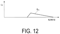
- FIG. 12 is a graph showing a relationship between a pilot ratio correction value Cp and the combustion load command value CLCSO according to the embodiment of the present invention.
- FIG. 13 is a graph showing a relationship between a pre-correction top hat ratio (TH 0 ratio) and the combustion load command value CLCSO according to the embodiment of the present invention.
- FIG. 14 is a graph showing a relationship between the pre-correction top hat ratio (TH 0 ratio) and a post-correction tap hat ratio (TH ratio), and a load factor % Load; and a relationship between a top hat ratio correction value Ct and the load factor % Load according to the embodiment of the present invention.
- FIGS. 15 A to 15 F are graphs showing changes in various parameters depending on changes in a state of a gas turbine according to the embodiment of the present invention.
- FIG. 15 A is a graph showing a relationship between the load factor % Load and the IGV opening.
- FIG. 15 B is a graph showing a relationship between the load factor % Load and the combustion load command value CLCSO.
- FIG. 15 C is a graph showing a relationship between the combustion load command value CLCSO and the pre-correction pilot ratio (PL 0 ratio).
- FIG. 15 D is a graph showing a relationship between the load factor % Load and the pre-correction pilot ratio (PL 0 ratio).
- FIG. 15 A is a graph showing a relationship between the load factor % Load and the IGV opening.
- FIG. 15 B is a graph showing a relationship between the load factor % Load and the combustion load command value CLCSO.
- FIG. 15 C is a graph showing a relationship between the combustion
- FIG. 15 E is a graph showing a relationship between the load factor % Load and the correction value Cp.
- FIG. 15 F is a graph showing a relationship between the load factor % Load and the post-correction and pre-correction pilot ratios (PL ratio and PL 0 ratio, respectively).
- FIG. 16 is a flowchart illustrating operations of the control device according to the embodiment of the present invention.
- FIG. 17 is an explanatory diagram illustrating various parameters expressing combustion states of fuel in the combustor.
- FIG. 18 is a function block diagram illustrating a flow volume ratio calculation device according to a variation on the embodiment of the present invention.
- the gas turbine plant includes a gas turbine 10 , and a generator 29 that is driven by the gas turbine 10 to generate power.
- the gas turbine 10 includes a compressor 11 that compresses air, a combustor 31 that combusts a fuel F in the air compressed by the compressor 11 to generate combustion gas, and a turbine 21 that is driven by the high-temperature high-pressure combustion gas.
- the compressor 11 includes a compressor rotor 13 that rotates about an axis of the compressor 11 , a compressor casing 12 that covers the compressor rotor 13 while allowing the compressor rotor 13 to rotate, and an inlet guide vane (IGV) 14 provided at an intake port of the compressor casing 12 .
- the ICV 14 includes multiple guide vanes 15 and a driver 16 that drives the multiple guide vanes 15 .
- the IGV 14 adjusts a flow volume of the air taken into the compressor casing 12 .
- the turbine 21 includes a turbine rotor 23 that is rotated about the axis by the combustion gas from the combustor 31 , and a turbine casing 22 that covers the turbine rotor 23 while allowing the turbine rotor 23 to rotate.
- the turbine rotor 23 and the compressor rotor 13 rotate around the same axis, and are connected to each other to form a gas turbine rotor 28 .
- a rotor of the generator 29 is connected to this gas turbine rotor 28 .
- the combustor 31 includes: an external cylinder 32 fixed to the turbine casing 22 ; a combustion liner 33 (or transition piece) 33 that is disposed within the turbine casing 22 and guides the combustion gas into a combustion gas flow channel of the turbine 21 ; and a fuel supplier 41 that supplies fuel and air to the combustion liner 33 .
- the fuel supplier 41 includes: a combustor basket 42 ; a pilot burner (first burner) 43 disposed on the central axial line of the combustor basket 42 ; multiple main burners (second burners) 53 disposed at equal intervals in a circumferential direction around the pilot burner 43 ; and a top hat nozzle 51 disposed on an inner peripheral side of the external cylinder 32 and an outer peripheral side of the combustor basket 42 .
- a side toward which combustion gas G flows in the combustion liner 33 will be called a “downstream side” and the side opposite therefrom will be called an “upstream side”.
- the pilot burner 43 includes a pilot nozzle 44 disposed on the central axial line of the combustor basket 42 and a tubular pilot air tube 45 surrounding the outer periphery of the pilot nozzle 44 .
- a downstream side of the pilot air tube 45 forms a pilot cone 46 whose diameter gradually becomes larger toward the downstream side.
- the inner peripheral side of the pilot air tube 45 forms a pilot air channel 48 through which a compressed air Ac from the compressor 11 flows as a pilot air Ap.
- a pilot fuel Fp sprayed from the pilot nozzle 44 is combusted (through diffusion combustion) in the pilot air Ap discharged from the pilot air channel 48 to form a diffusion flame 49 .
- Each of the main burners 53 includes: a tubular main air internal cylinder 55 surrounding the outer periphery of the pilot air tube 45 ; a tubular main air external cylinder 56 surrounding the outer periphery of the main air internal cylinder 55 ; multiple partitioning plates 57 ; and a main nozzle 54 disposed between the multiple partitioning plates 57 .
- the multiple partitioning plates 57 divide an annular space between the outer peripheral side of the main air internal cylinder 55 and the inner peripheral side of the main air external cylinder 56 into multiple spaces in the circumferential direction.
- the multiple spaces defined by the main air internal cylinder 55 , the main air external cylinder 56 , and the multiple partitioning plates 57 form a main air channel 58 in which the compressed air Ac from the compressor 11 flows as a main air Am.
- a main fuel Fm is sprayed from the main nozzle 54 disposed within the main air channel 58 into the main air Am flowing in the main air channel 58 .
- premixed gas which is a mixture of the main air Am and the main fuel Fm, flows in the main air channel 58 , from a tip end portion (downstream end) of the main nozzle 54 toward the downstream side.
- this premixed gas After flowing out of the main air channel 58 , this premixed gas is combusted (through premixed combustion) and forms a premixed flame 59 .
- the above-described diffusion flame 49 fulfills a role of stabilizing this premixed flame 59 .
- the top hat nozzle 51 sprays a top hat fuel Ft into this compressed air channel 52 .
- the top hat fuel Ft is mixed into the main air Am and the pilot air Ap.
- the gas turbine plant further includes: a pilot fuel line (first fuel system) 61 that guides the pilot fuel Fp to the pilot nozzle 44 ; a main fuel line (second fuel system) 62 that guides the main fuel Fm to the main nozzle 54 ; a top hat fuel line (upstream supply system) 63 that guides the top hat fuel Ft to the top hat nozzle 51 ; a pilot fuel valve 65 that adjusts a flow volume of the pilot fuel Fp; a main fuel valve 66 that adjusts a flow volume of the main fuel Fm; a top hat fuel valve 67 that adjusts a flow volume of the top hat fuel Ft; and a control device 100 that controls operations of the fuel valves 65 , 66 , 67 , and the like.
- the pilot fuel line 61 , the main fuel line 62 , and the top hat fuel line 63 all branch out from a fuel line 60 .
- the pilot fuel valve 65 is provided in the pilot fuel line 61
- the main fuel valve 66 is provided in the main fuel line 62
- the top hat fuel valve 67 is provided in the top hat fuel line 63 .
- the gas turbine plant further includes: an RPM gauge 71 that detects an RPM N of the gas turbine rotor 28 ; an output gauge 72 that detects an output PW of the generator 29 ; an intake temperature gauge 73 that detects an intake temperature Ti, which is a temperature of air A taken in by the compressor 11 ; an intake pressure gauge 74 that detects an intake pressure (atmospheric pressure) Pi, which is a pressure of the air taken in by the compressor 11 ; a blade path temperature gauge 75 that detects a blade path temperature Tb; and an exhaust gas temperature gauge 76 that detects a temperature Te of exhaust gas.
- an RPM gauge 71 that detects an RPM N of the gas turbine rotor 28
- an output gauge 72 that detects an output PW of the generator 29
- an intake temperature gauge 73 that detects an intake temperature Ti, which is a temperature of air A taken in by the compressor 11
- an intake pressure gauge 74 that detects an intake pressure (atmospheric pressure) Pi, which is a pressure of the air
- the blade path temperature Tb detected by the blade path temperature gauge 75 is the temperature of the combustion gas immediately after a final stage of the turbine 21 .
- the temperature Te of the exhaust gas detected by the exhaust gas temperature gauge 76 is the temperature of the exhaust gas within an exhaust duct downstream from the final stage of the turbine 21 .
- the control device 100 includes: an interface 180 that receives detection values from the detection gauges and the like; a combustion load command generator 110 that generates a combustion load command value CLCSO; a load factor computer 120 that determines a current load factor % Load of the gas turbine 10 ; a fuel flow volume command generator 130 that generates a fuel flow volume command value CSO; a pilot ratio calculator 140 p that calculates a pilot ratio (PL ratio), which is a ratio of a pilot fuel flow volume Fpf to a total fuel flow volume; a top hat ratio calculator 140 t that calculates a top hat ratio (TH ratio), which is a ratio of a top hat fuel flow volume Ftf to the total fuel flow volume; a system flow volume computer 160 that determines flow volumes in the fuel lines 61 , 62 , and 63 ; and a valve controller 170 that outputs control signals to the fuel valves 65 , 66 , and 67 in accordance with the respective flow volumes in the fuel
- the combustion load command value CLCSO is a parameter that is obtained by nondimensionalizing an inlet temperature of the combustion gas in the turbine 21 and that has a positive correlation with the inlet temperature.
- the combustion load command value CLCSO is set so as to be 0% when the inlet temperature is at its lower limit and 100% when the inlet temperature is at its upper limit. For example, when the lower limit of the inlet temperature is 700° C. and the upper limit of the inlet temperature is 1,500° C., the combustion load command value CLCSO is expressed by the following equation.
- CLCSO (%) ⁇ (measured value of generator output ⁇ 700° CMW)/(1,500° CMW ⁇ 700° CMW) ⁇ 100,
- 700° CMW is the generator output when the inlet temperature is at its lower limit of 700° C.
- 1,500° CMW is the generator output when the inlet temperature is at its upper limit of 1,500° C.
- the combustion load command generator 110 includes a first output computer 111 a , a second output computer 111 b , a standard atmospheric pressure generator 112 , a first divider 113 , a first multiplier 114 a , a second multiplier 114 b , a first subtractor 115 a , a second subtractor 115 b , a second divider 116 , and a limiter 117 .
- the first output computer 111 a determines the generator output 700° CMW occurring when the inlet temperature is at its lower limit of 700° C.
- the second output computer 111 b determines the generator output 700° 1500° CMW occurring when the inlet temperature is at its upper limit of 1,500° C.
- the standard atmospheric pressure generator 112 generates a preset standard atmospheric pressure Ps.
- the first divider 113 determines an intake pressure ratio Pr, which is a ratio of the intake pressure Pi detected by the intake pressure gauge 74 to the standard atmospheric pressure (standard intake pressure) Ps.
- the first multiplier 114 a multiplies the generator output 700° CMW, determined by the first output computer 111 a , by the intake pressure ratio Pr.
- the second multiplier 114 b multiplies the generator output 1,500° CMW, determined by the second output computer 111 b , by the intake pressure ratio Pr.
- the first subtractor 115 a subtracts the multiplication result obtained by the first multiplier 114 a from the measured output PW of the generator 29 detected by the output gauge 72 .
- the second subtractor 115 b subtracts the multiplication result obtained by the first multiplier 114 a from the multiplication result obtained by the second multiplier 114 b .
- the second divider 116 divides the subtraction result obtained by the first subtractor 115 a by the subtraction result obtained by the second subtractor 115 b .
- the limiter 117 limits an increase/decrease rate of the output from the second divider 116 .
- the first output computer 111 a determines the generator output 700° CMW occurring when the inlet temperature is 700° C. using a function H 1 x, with the intake temperature Ti and an IGV opening command value defined as variable parameters.
- the second output computer 111 b determines the generator output 1500° CMW occurring when the inlet temperature is 1,500° C. using a function H 2 x, with the intake temperature Ti and the IGV opening command value defined as variable parameters.
- the IGV opening command value is a command value that is supplied to the driver 16 of the IGV 14 by the control device 100 , and that specifies an IGV opening.
- This IGV opening command value is determined, for example, from the atmospheric pressure Pi, which is the pressure at the inlet of the compressor 11 , a pressure at the outlet of the compressor 11 , the current load factor % Load of the gas turbine 10 , and the like.
- a relationship between the load factor % Load and the IGV opening is, as shown in FIG. 10 , for example, a relationship in which the IGV opening increases as the load factor % Load increases.
- the amount of increase in the IGV opening relative to the amount of increase in the load factor % Load, the load factor % Load at which the IGV opening begins to increase, and the like are changed depending on the operation plan for the gas turbine 10 , the atmospheric pressure Pi, which is the pressure at the inlet of the compressor 11 , and the like.
- the IGV opening may be determined using the output PW of the generator 29 , which is the output of the gas turbine 10 , instead of the load factor % Load.
- the 700° CMW and 1,500° CMW are corrected in accordance with a measured value Pi of the intake pressure (atmospheric pressure).
- the first, divider 113 determines the intake pressure ratio Pr, which is a ratio of the intake pressure (atmospheric pressure) Pi detected by the intake pressure gauge 74 to the standard atmospheric pressure (standard intake pressure) Ps from the standard atmospheric pressure generator 112 .
- the first multiplier 114 a multiplies the 700° CMW from the first output computer 111 a by the intake pressure ratio Pr to correct the 700° CMW to a value corresponding to the intake pressure ratio Pr.
- the first subtractor 115 a subtracts the 700° CMW corrected with the intake pressure ratio Pr from the measured output PW of the generator 29 detected by the output gauge 72 . In other words, the first subtractor 115 a determines the value of the numerator in the above equation.
- the second subtractor 115 b subtracts the 700° CMW corrected with the intake pressure ratio Pr from the 1,500° CMW corrected with the intake pressure ratio Pr. In other words, the second subtractor 115 b determines the value of the denominator in the above equation.
- the second divider 116 divides the value of the numerator in the above equation, determined by the first subtractor 115 a , by the value of the denominator in the above equation, determined by the second subtractor 115 b , and outputs the resulting value as the combustion load command value.
- the limiter 117 limits the increase/decrease rate of the combustion load command value, which is an amount of change in the combustion load command value from the second divider 116 per unit time, so that the increase/decrease rate is less than or equal to a predetermined value.
- the lower limit of the inlet temperature of the combustion gas in the turbine 21 as being 700° C. and the upper limit thereof being 1,500° C., depending on the model type of the combustor 31 and the like, the lower limit and upper limit of the inlet temperature of the combustion gas in the turbine 21 may have different values from those in the above example.
- the combustion load command value CLCSO is output from the combustion load command generator 110 .
- the load factor % Load of the gas turbine 10 is a percentage of a current load PW relative to a maximum load PWmax permitted in the current state of the gas turbine 10 .
- the load factor computer 120 includes a maximum load computer 121 that determines the maximum load PWmax permitted in the current state of the gas turbine 10 , and a divider 127 that divides the measured load PW, which is the output of the generator 29 detected by the output gauge 72 , by the maximum load PWmax.
- the fuel flow volume command value CSO is a value specifying a total flow volume of the fuel supplied to the combustor 31 (referred to as “total fuel flow volume” hereinafter).
- total fuel flow volume a value specifying a total flow volume of the fuel supplied to the combustor 31 (referred to as “total fuel flow volume” hereinafter).
- the fuel flow volume command generator 130 functions as a total flow volume computer. Therefore, as will be described later, the fuel flow volume command generator 130 executes a total fuel flow volume computing step in which the total fuel flow volume is determined.
- the fuel flow volume command generator 130 includes a governor controller 131 , a load controller 132 , a first temperature controller 133 , a second temperature controller 134 , a low value selector 135 , and a limiter 136 .
- the governor controller 131 outputs a command value for controlling the total fuel flow volume so that the RPM N of the gas turbine rotor 28 becomes a target RPM.
- the load controller 132 outputs a command value for controlling the total fuel flow volume so that the generator output PW matches a generator output command value.
- the first temperature controller 133 outputs a command value for controlling the total fuel flow volume so that the blade path temperature Tb of the gas turbine does not exceed its upper limit.
- the governor controller 131 receives the RPM N of the gas turbine rotor 28 from the RPM gauge 71 and outputs a command value GVCSO for controlling the total fuel flow volume so that the RPM N of the gas turbine rotor 28 matches the target RPM. Specifically, the governor controller 131 compares the measured RPM N of the gas turbine rotor 28 with a preset GV setting value, and outputs a proportional control signal as the command value GVCSO.
- the PL 0 ratio computer 141 p has a function F 1 x defining a relationship between the combustion load command value CLCSO, which has a positive correlation with the inlet temperature of the combustion gas in the turbine 21 , and the PL 0 ratio.
- the function F 1 x is a function in which the PL 0 ratio gradually decreases as the combustion load command value CLCSO increases, or in other words, as the inlet temperature of the combustion gas rises.
- the PL 0 ratio computer 141 p receives the combustion load command value CLCSO from the combustion load command generator 110 , and determines the PL 0 ratio corresponding to that combustion load command value CLCSO using the function F 1 x.
- the relationship between the combustion load command value CLCSO and the PL 0 ratio is defined by the function F 1 x here, the relationship may be defined by a map.
- the correction value computer 142 p has a function G 1 x defining a relationship between the load factor % Load and the correction value Cp.
- the correction value computer 142 p receives the load factor % Load from the load factor computer 120 , and determines a correction value Ci based on the current load factor % Load using the function G 1 x.
- the relationship between the load factor % Load and the correction value Cp is defined by the function G 1 x here, the relationship may be defined by a map.
- the top hat ratio (TH ratio) is a ratio of the top hat fuel flow volume Ftf to the total fuel flow volume.
- the top hat ratio calculator 140 t includes: a TH 0 ratio computer (flow volume ratio computer) 141 t that determines the TH 0 ratio, which is the top hat ratio based on the combustion load command value CLCSO; a correction value computer 142 t that determines a correction value based on the load factor % Load; a fluctuation detector 144 that detects fluctuation in the fuel flow volume command value CSO; and a corrector 144 t that corrects the TH 0 ratio with the correction value Ct.
- a TH 0 ratio computer flow volume ratio computer
- the system flow volume computer 160 includes: a first multiplier 161 that determines the pilot fuel flow volume Fpf using the PL ratio determined by the pilot ratio calculator 140 p ; a second multiplier 162 that determines the top hat fuel flow volume Ftf from the TH ratio determined by the top hat ratio calculator 140 t ; a first subtractor 163 that subtracts the top hat fuel flow volume Ftf from the fuel flow volume command value CSO specifying the total fuel flow volume; and a second subtractor 164 that further subtracts the pilot fuel flow volume Fpf from the subtraction result obtained by the first subtractor 163 .
- the valve drive amount computer 171 that determines the drive amount of the pilot fuel valve 65 determines the drive amount of the pilot fuel valve 65 in accordance with the pilot fuel flow volume Fpf determined by the system flow volume computer 160 .
- the valve control signal outputter 175 creates a control signal in accordance with the drive amount of the pilot fuel valve 65 and outputs the control signal to the pilot fuel valve 65 .
- the valve drive amount computer 172 that determines the drive amount of the top hat fuel valve 67 determines the drive amount of the top hat fuel valve 67 in accordance with the top hat fuel flow volume Ftf determined by the system flow volume computer 160 .
- the valve control signal outputter 176 creates a control signal in accordance with the drive amount of the top hat fuel valve 67 and outputs the control signal to the top hat fuel valve 67 .
- the valve drive amount computer 173 that determines the drive amount of the main fuel valve 66 determines the drive amount of the main fuel valve 66 in accordance with the main fuel flow volume Fmf determined by the system flow volume computer 160 .
- the valve control signal outputter 177 creates a control signal in accordance with the drive amount of the main fuel valve 66 and outputs the control signal to the main fuel valve 66 .
- the valve controller 170 executes a valve controlling step in which the control signal is output to each of the fuel valves.
- the combustion load command generator 110 determines the combustion load command value CLCSO, which is a parameter having a positive correlation with the inlet temperature of the combustion gas in the turbine 21 , using the measured output PW of the generator 29 detected by the output gauge 72 , the IGV opening command value, the intake pressure Pi detected by the intake pressure gauge 74 , and the intake temperature Ti detected by the intake temperature gauge 73 (S 10 : an inlet temperature-correlated value computing step).
- CLCSO combustion load command value
- the load factor computer 120 determines the current load factor % Load of the gas turbine 10 (S 20 : a load factor computing step). At this time, as described earlier, the load factor computer 120 determines the maximum load PWmax of the gas turbine 10 , based on the current intake pressure Pi and intake temperature Ti, from the intake pressure Pi detected by the intake pressure gauge 74 and the intake temperature Ti detected by the intake temperature gauge 73 . The load factor computer 120 divides the measured load PW, which is the output of the generator 29 detected by the output gauge 72 , by the maximum load PWmax, and outputs the resulting value as the load factor % Load.
- the fuel flow volume command generator 130 determines the fuel flow volume command value CSO, which specifies the total flow volume of the fuel supplied to the combustor of the gas turbine 10 (S 30 : a total flow volume computing step). At this time, as described earlier, the fuel flow volume command generator 130 determines multiple command values and outputs the minimum or lowest value among the multiple command values as the fuel flow volume command value CSO.
- the pilot ratio calculator 140 p receives the combustion load command value CLCSO output by the combustion load command generator 110 and the load factor % Load output by the load factor computer 120 (S 41 p : a receiving step). From the value and factor, the PL ratio is determined (S 42 p : a PL ratio computing step). In the PL ratio computing step (S 42 p ), first, as described earlier, the PL 0 ratio computer 141 p determines the PL 0 ratio corresponding to the combustion load command value CLCSO received earlier, using the function F 1 x (S 43 p : a PL 0 ratio computing step).
- the correction value computer 142 p determines the correction value Cp corresponding to the load factor % Load received earlier, using the function G 1 x (S 44 p : a correction value Cp computing step). Then, the corrector 144 p adds the correction value Cp to the PL 0 ratio and outputs the resulting value as a corrected pilot ratio (PL ratio) (S 45 p : a correcting step).
- the top hat ratio calculator 140 t receives the combustion load command value CLCCSO output by the combustion load command generator 110 and the load factor % Load output by the load factor computer 120 (S 41 t : a receiving step). From the value and factor, the TH ratio is determined (S 42 t : a ratio computing step).
- the TH 0 ratio computer 141 t determines the TH 0 ratio corresponding to the combustion load command value CLCSO received earlier, using the function F 2 x (S 43 t : a TH 0 ratio computing step), Next, or in parallel with the TH 0 ratio computing step (S 43 t ), the correction value computer 142 t determines the correction value Ct corresponding to the load factor % Load received earlier, using the function G 2 x (S 44 t : a correction value Ct computing step). Then, the corrector 144 t adds the correction value Ct to the TH 0 ratio and outputs the resulting value as a corrected pilot ratio (PL ratio) (S 45 t : a correcting step).
- PL ratio corrected pilot ratio
- the system flow volume computer 160 determines the pilot fuel flow volume Fpf, the top hat fuel flow volume Ftf, and the main fuel flow volume Fmf relative to the total fuel flow volume indicated by the fuel flow volume command value CSO, from the PL ratio determined by the pilot ratio calculator 140 p and the TH ratio determined by the top hat ratio calculator 140 t , and outputs the flow volumes to the valve controller 170 (S 50 : the system flow volume computing step).
- the valve controller 170 determines the drive amount of the pilot fuel valve 65 such that the pilot fuel flow volume Fpf can be secured, and outputs a control signal specifying that drive amount to the pilot fuel valve 65 .
- the valve controller 170 determines the drive amount of the main fuel valve 66 such that the main fuel flow volume Fmf can be secured, and outputs a control signal specifying that drive amount to the main fuel valve 66 .
- the valve controller 170 determines the drive amount of the top hat fuel valve 67 such that the top hat fuel flow volume Ftf can be secured, and outputs a control signal specifying that drive amount to the top hat fuel valve 67 (S 60 : the valve controlling step).
- the fuel valves 65 , 66 , and 67 operate in accordance with the drive amounts specified by the respective control signals.
- the pilot fuel Fp flows into the pilot fuel line 61 at the flow volume Fpf in accordance with the PL ratio determined by the pilot ratio calculator 140 p .
- the top hat fuel Ft flows into the top hat fuel line 63 at the flow volume Ftf in accordance with the TH ratio determined by the top hat ratio calculator 140 t .
- the main fuel Fm flows into the main fuel line 62 at the flow volume Fmf obtained by subtracting the pilot fuel flow volume Fpf and the top hat fuel flow volume Ftf from the total fuel flow volume.
- the series of controlling steps for the fuel valves 65 , 66 , and 67 executed by the control device 100 is then terminated. These controlling steps are executed repeatedly each time the interface 180 receives the detection values from the respective detection gauges and the like, for example.
- the IGV opening is constant at a minimum opening, up to the state S 4 , where the load factor % Load is a middle load factor of approximately 50%, for example, as shown in FIG. 15 A .
- the load factor % Load is a middle load factor of approximately 50%, for example, as shown in FIG. 15 A .
- the IGV opening increases as the load factor % Load increases. This trend continues until the state S 5 , which is immediately before the load factor % Load reaches 100%.
- the IGV opening reaches 100% in the state S 5 .
- the IGV opening is constant at 100%, from the state S 5 , which is immediately before the load factor % Load reaches 100%, to the state S 6 in which the load factor % Load is 100%.
- the graph of FIG. 15 A is the same as the graph of FIG. 10 .
- the inlet temperature of the combustion gas in the turbine 21 , and the combustion load command value CLCSO having a positive correlation therewith increase as a fuel/air ratio (fuel/air) increases.
- the inlet temperature and the combustion load command value CLCSO are also substantially constant even if the load factor % Load increases.
- the inlet temperature and the combustion load command value CLCSO also increase, regardless of an increase/decrease in the load factor % Load.
- the IGV opening is constant at the minimum opening, and an intake flow volume of the compressor 11 is substantially constant, from the state S 1 of a minimum load factor to the state S 4 of the middle load factor.
- the flow volume of the fuel supplied to the combustor 31 of the gas turbine 10 increases as the load factor % Load increases even outside this period.
- the combustion load command value CLCSO also increases in this period, as shown in FIG. 15 B .
- the IGV opening increases as the load factor % Load increases, and the intake flow volume of the compressor 11 also increases as the load factor % Load increases, from the state S 4 of the middle load factor to the state S 5 immediately before the load factor % Load reaches 100%.
- the flow volume of the fuel supplied to the combustor 31 of the gas turbine 10 increases as the load factor % Load increases even in this period.
- the fuel/air ratio undergoes almost no change
- the combustion load command value CLCSO also undergoes almost no change, even if the load factor % Load increases.
- the combustion load command value CLCSO is substantially constant in this period.
- the pre-correction PL 0 ratio is set to gradually decrease as the combustion load command value CLCSO increases (see FIG. 15 C ).
- the pre-correction PL 0 ratio gradually decreases as the load factor % Load increases, as shown in FIG. 15 D .
- the pre-correction PL 0 ratio is substantially constant even if the load factor % Load increases. Note that the graph of FIG. 15 C is the same as the graph of FIG. 11 .
- the combustion state within the combustion liner 33 of the combustor 31 changes if the load factor % Load changes, even if the combustion load command value CLCSO, or in other words, the inlet temperature of the combustion gas in the turbine 21 , is constant.
- the pilot ratio (PL ratio) is one of the operation parameters of the gas turbine 10 that is changed in order to ensure combustion stability while ensuring the exhaust gas from the gas turbine 10 meets an environmental regulation value.
- the pre-correction PL 0 ratio is constant, in the case where the combustion load command value CLCSO is constant despite the load factor % Load changing and the combustion state within the combustion liner 33 changing, it may not be possible to ensure the combustion stability if the pre-correction PL 0 ratio is applied as-is.
- the PL 0 ratio is corrected with the correction value Cp so that the PL ratio is set to a region excluding regions Ri (regions determined by the PL ratio and the load factor % Load) where the combustion state becomes unstable, such as the occurrence of combustion oscillation, in the case where the load factor % Load changes despite the combustion load command value CLCSO being constant, as shown in FIG. 15 F .
- the correction value Cp is determined as follows.
- the regions Ri regions determined by the PL ratio and the load factor % Load
- the regions Ri regions determined by the PL ratio and the load factor % Load
- a relationship between the PL ratio and the load factor % Load that makes it possible to avoid the regions Ri where the combustion state becomes unstable when the combustion load command value CLCSO is constant is determined.
- a difference between the PL ratio relative to the load factor % Load determined from this relationship and the PL 0 ratio determined in accordance with the combustion load command value CLCSO is taken as the correction value Cp, as shown in FIG. 15 E .
- the graph of FIG. 15 E is the same as the graph of FIG. 12 .
- the combustion stability can be improved by adding the correction value Cp in accordance with the current load factor % Load to the pre-correction PL 0 ratio and taking the resulting value as a final PL ratio.
- the TH 0 ratio is corrected with the correction value Ct so that the TH ratio is set to a region excluding the regions Ri (regions determined by the TH ratio and the load factor % Load) where the combustion state becomes unstable in the case where the load factor % Load changes despite the combustion load command value CLCSO being constant, as shown in FIG. 14 .
- the correction value Ct is determined as follows, in the same manner as the correction value Cp described earlier.
- the regions Ri regions determined by the TH ratio and the load factor % Load
- the regions Ri regions determined by the TH ratio and the load factor % Load
- a relationship between the TH ratio and the load factor % Load that makes it possible to avoid the regions Ri where the combustion state becomes unstable when the combustion load command value CLCSO is constant is determined.
- a difference between the TH ratio relative to the load factor % Load determined from this relationship and the TH 0 ratio determined in accordance with the combustion load command value CLCSO is taken as the correction value Ct.
- the combustion state of the fuel within the combustion liner 33 of the combustor 31 can be expressed by the inlet temperature of the combustion gas in the turbine 21 and a gas flow velocity within the combustion liner 33 .
- the combustion load command value CLCSO is a value having a positive correlation with the inlet temperature of the combustion gas in the turbine 21 .
- the load factor % Load has a positive correlation with the gas flow volume in the combustion liner 33 , it can also be said that the load factor % Load is a value having a positive correlation with the gas flow velocity within the combustion liner 33 .
- the PL ratio and the like in accordance with the combustion state are determined from the combustion load command value CLCSO and the load factor % Load.
- the combustion state can thus be understood more accurately than when determining the PL ratio and the like in accordance with the combustion state determined by the combustion load command value CLCSO only, and the PL ratio and the like can be determined in accordance with that combustion state.
- the occurrence of combustion oscillation within the combustion liner 33 of the combustor and the like can be suppressed, and the combustion stability within the combustion liner 33 can be further improved.
- the combustion state of the fuel within the combustion liner 33 of the combustor 31 can be expressed by two parameters. As described earlier, of the two parameters, a first parameter is a parameter correlated with the inlet temperature of the combustion gas in the turbine 21 , and a second parameter is a parameter correlated with the gas flow velocity within the combustion liner 33 .
- the inlet temperature of the combustion gas in the turbine 21 may be used as the first parameter instead of the combustion load command value CLCSO described above.
- this gas flow volume includes, in addition to the load factor % Load described in the above embodiment, the output of the gas turbine 10 , a total flow volume Gf of the fuel F supplied to the combustor 31 from the multiple fuel systems, and a flow volume Ga of the air A taken in by the compressor 11 .
- the output of the gas turbine 10 can be expressed by the output PW of the generator 29 connected to the gas turbine 10 .
- the output PW of the generator 29 detected by the output gauge 72 can be used as the second parameter.
- the flow volume of the air A taken in by the compressor 11 can be detected directly with a flow volume gauge, only a few plants are provided with such a flow volume gauge.
- a relationship between a mass flow volume Ga of the air A taken in by the compressor 11 , the IGV opening, and the intake temperature may be found in advance, and that relationship may then be used to determine the mass flow volume Ga of the air A taken in by the compressor 11 from the IGV opening specified by the IGV opening command value and the intake temperature detected by the intake temperature gauge 73 .
- the mass flow volume Ga of the air A taken in by the compressor 11 is a mass flow volume when the generator 29 connected to the gas turbine 10 is connected to a power system and the RPMs of the generator 29 and the gas turbine 10 correspond to a system frequency.
- the combustion state of the fuel within the combustion liner 33 of the combustor 31 can be expressed by the total flow volume of the fuel supplied to the combustor 31 and the flow volume of the air supplied to the combustor 31 , or in other words, the flow volume of the air taken in by the compressor 11 . Accordingly, the total flow volume of the fuel supplied to the combustor 31 can be used as the first parameter and the flow volume of the air taken in by the compressor 11 can be used as the second parameter.
- the flow volume of the fuel detected by the flow volume gauge 78 provided in the fuel line 60 or the flow volume of the fuel specified by a valve lift command value of the flow volume adjustment valve 79 can be used as the first parameter, and the flow volume of the air taken in by the compressor 11 determined through the method described earlier can be used as the second parameter.
- a flow volume ratio calculation device 141 A includes: a pilot ratio calculator 140 Ap that receives the values of the first parameter and the second parameter, examples of which have been given above, and calculates the PL ratio; and a top hat ratio calculator 140 At that receives the values of the first parameter and the second parameter, examples of which have been given above, and calculates the TH ratio.
- the pilot ratio calculator 140 Ap includes a PL 0 ratio computer (flow volume ratio computer) 141 Ap that determines the PL 0 ratio in accordance with the value of the first parameter, a correction value computer 142 Ap that calculates the correction value Cp in accordance with the value of the second parameter, and a corrector 144 Ap that corrects the PL 0 ratio with the correction value Cp.
- a PL 0 ratio computer flow volume ratio computer
- the PL 0 ratio computer 141 Ap has a function defining a relationship between the first parameter and the PL 0 ratio.
- the correction value computer 142 A p has a function defining a relationship between the second parameter and the correction value Cp.
- the top hat ratio calculator 140 At includes a TH 0 ratio computer (flow volume ratio computer) 141 At that determines the TH 0 ratio in accordance with the value of the first parameter, a correction value computer 142 At that calculates the correction value Ct in accordance with the value of the second parameter, and a corrector 144 At that corrects the TH 0 ratio with the correction value Ct.
- a TH 0 ratio computer flow volume ratio computer
- the TH 0 ratio computer 141 At has a function defining a relationship between the first parameter and the TH 0 ratio.
- the correction value computer 142 At has a function defining a relationship between the second parameter and the correction value Ct.
- the combustion stability of fuel within a combustor can be improved.
Landscapes
- Engineering & Computer Science (AREA)
- Chemical & Material Sciences (AREA)
- Combustion & Propulsion (AREA)
- Mechanical Engineering (AREA)
- General Engineering & Computer Science (AREA)
- Control Of Turbines (AREA)
Applications Claiming Priority (3)
| Application Number | Priority Date | Filing Date | Title |
|---|---|---|---|
| JP2014160606A JP6332747B2 (ja) | 2014-08-06 | 2014-08-06 | 流量比算出装置、これを備えている制御装置、この制御装置を備えているガスタービンプラント、流量比算出方法、及び燃料系統の制御方法 |
| JP2014-160606 | 2014-08-06 | ||
| PCT/JP2015/070502 WO2016021390A1 (ja) | 2014-08-06 | 2015-07-17 | 流量比算出装置、これを備えている制御装置、この制御装置を備えているガスタービンプラント、流量比算出方法、及び燃料系統の制御方法 |
Publications (2)
| Publication Number | Publication Date |
|---|---|
| US20170292458A1 US20170292458A1 (en) | 2017-10-12 |
| US11773789B2 true US11773789B2 (en) | 2023-10-03 |
Family
ID=55263663
Family Applications (1)
| Application Number | Title | Priority Date | Filing Date |
|---|---|---|---|
| US15/321,459 Active 2037-09-19 US11773789B2 (en) | 2014-08-06 | 2015-07-17 | Flow volume ratio calculation device, control device equipped with same, gas turbine plant equipped with this control device, flow volume ratio calculation method, and fuel line control method |
Country Status (6)
| Country | Link |
|---|---|
| US (1) | US11773789B2 (ja) |
| JP (1) | JP6332747B2 (ja) |
| KR (1) | KR101885453B1 (ja) |
| CN (1) | CN106460678B (ja) |
| DE (1) | DE112015003596T5 (ja) |
| WO (1) | WO2016021390A1 (ja) |
Families Citing this family (10)
| Publication number | Priority date | Publication date | Assignee | Title |
|---|---|---|---|---|
| JP6223847B2 (ja) * | 2014-02-05 | 2017-11-01 | 三菱日立パワーシステムズ株式会社 | ガスタービンの制御装置、ガスタービン、及びガスタービンの制御方法 |
| KR101898386B1 (ko) | 2017-04-24 | 2018-09-12 | 두산중공업 주식회사 | 가스터빈 시스템 및 제어 방법 |
| KR101971337B1 (ko) | 2017-04-24 | 2019-04-22 | 두산중공업 주식회사 | 가스터빈 시스템 및 제어 방법 |
| JP6935327B2 (ja) * | 2017-12-28 | 2021-09-15 | 三菱パワー株式会社 | 制御装置、ガスタービン、制御方法及びプログラム |
| EP3530912A1 (en) | 2018-02-23 | 2019-08-28 | Siemens Aktiengesellschaft | Controller and method |
| EP3530913A1 (en) | 2018-02-23 | 2019-08-28 | Siemens Aktiengesellschaft | Controller and method |
| JP7176932B2 (ja) * | 2018-11-08 | 2022-11-22 | 三菱重工業株式会社 | ガスタービンの制御装置、ガスタービン設備、ガスタービンの制御方法、及びガスタービンの制御プログラム |
| KR20230071178A (ko) | 2020-10-30 | 2023-05-23 | 미츠비시 파워 가부시키가이샤 | 가스 터빈의 최대 출력 작성 방법, 가스 터빈의 제어용 출력 작성 방법, 가스 터빈의 제어 방법, 이들 방법을 실행하는 장치, 및 이들 방법을 컴퓨터에 실행시키는 프로그램 |
| WO2023181616A1 (ja) * | 2022-03-25 | 2023-09-28 | 三菱パワー株式会社 | ガスタービン設備の運転方法、この運転方法を実行するための制御装置及び制御プログラム |
| JP2024067373A (ja) * | 2022-11-04 | 2024-05-17 | 三菱重工業株式会社 | ガスタービン燃焼器の制御装置、制御方法及び始動方法 |
Citations (7)
| Publication number | Priority date | Publication date | Assignee | Title |
|---|---|---|---|---|
| JP2004108315A (ja) | 2002-09-20 | 2004-04-08 | Toshiba Corp | ガスタービンシステムおよびその運転方法 |
| JP2007077867A (ja) | 2005-09-14 | 2007-03-29 | Mitsubishi Heavy Ind Ltd | ガスタービンの燃焼制御装置 |
| JP2007077866A (ja) | 2005-09-14 | 2007-03-29 | Mitsubishi Heavy Ind Ltd | ガスタービンの燃焼制御装置 |
| JP2010127242A (ja) | 2008-11-28 | 2010-06-10 | Mitsubishi Heavy Ind Ltd | ガスタービン制御装置 |
| JP2012077662A (ja) | 2010-09-30 | 2012-04-19 | Mitsubishi Heavy Ind Ltd | ガスタービンの制御装置、ガスタービン、及びガスタービンの制御方法 |
| JP2013096303A (ja) | 2011-10-31 | 2013-05-20 | Mitsubishi Heavy Ind Ltd | ガスタービン及びガスタービンの燃焼制御方法 |
| US20130227954A1 (en) * | 2012-03-05 | 2013-09-05 | Bonnie D. Marini | Gas turbine engine configured to shape power output |
Family Cites Families (3)
| Publication number | Priority date | Publication date | Assignee | Title |
|---|---|---|---|---|
| JP5452634B2 (ja) * | 2012-01-06 | 2014-03-26 | 株式会社日立製作所 | 高湿分空気利用ガスタービンに設置されるガスタービン燃焼器の燃料制御方法及び燃料制御装置 |
| JP5486619B2 (ja) * | 2012-02-28 | 2014-05-07 | 株式会社日立製作所 | ガスタービン燃焼器及びその運転方法 |
| JP5957251B2 (ja) * | 2012-03-19 | 2016-07-27 | 株式会社東芝 | 自動改札装置および自動改札装置の制御方法 |
-
2014
- 2014-08-06 JP JP2014160606A patent/JP6332747B2/ja active Active
-
2015
- 2015-07-17 KR KR1020167035114A patent/KR101885453B1/ko active IP Right Grant
- 2015-07-17 CN CN201580032071.2A patent/CN106460678B/zh active Active
- 2015-07-17 US US15/321,459 patent/US11773789B2/en active Active
- 2015-07-17 WO PCT/JP2015/070502 patent/WO2016021390A1/ja active Application Filing
- 2015-07-17 DE DE112015003596.6T patent/DE112015003596T5/de active Pending
Patent Citations (8)
| Publication number | Priority date | Publication date | Assignee | Title |
|---|---|---|---|---|
| JP2004108315A (ja) | 2002-09-20 | 2004-04-08 | Toshiba Corp | ガスタービンシステムおよびその運転方法 |
| JP2007077867A (ja) | 2005-09-14 | 2007-03-29 | Mitsubishi Heavy Ind Ltd | ガスタービンの燃焼制御装置 |
| JP2007077866A (ja) | 2005-09-14 | 2007-03-29 | Mitsubishi Heavy Ind Ltd | ガスタービンの燃焼制御装置 |
| US20070079593A1 (en) * | 2005-09-14 | 2007-04-12 | Mitsubishi Heavy Industries, Ltd. | Combustion control device for gas turbine |
| JP2010127242A (ja) | 2008-11-28 | 2010-06-10 | Mitsubishi Heavy Ind Ltd | ガスタービン制御装置 |
| JP2012077662A (ja) | 2010-09-30 | 2012-04-19 | Mitsubishi Heavy Ind Ltd | ガスタービンの制御装置、ガスタービン、及びガスタービンの制御方法 |
| JP2013096303A (ja) | 2011-10-31 | 2013-05-20 | Mitsubishi Heavy Ind Ltd | ガスタービン及びガスタービンの燃焼制御方法 |
| US20130227954A1 (en) * | 2012-03-05 | 2013-09-05 | Bonnie D. Marini | Gas turbine engine configured to shape power output |
Non-Patent Citations (2)
| Title |
|---|
| International Search Report dated Sep. 8, 2015 in corresponding (PCT) International Application No. PCT/JP2015/070502 (with English translation). |
| Written Opinion of the International Searching Authority dated Sep. 8, 2015 in corresponding (PCT) International Application No. PCT/JP2015/070502 (with English translation). |
Also Published As
| Publication number | Publication date |
|---|---|
| KR20170007424A (ko) | 2017-01-18 |
| DE112015003596T5 (de) | 2017-06-08 |
| WO2016021390A1 (ja) | 2016-02-11 |
| CN106460678B (zh) | 2018-08-28 |
| JP6332747B2 (ja) | 2018-05-30 |
| CN106460678A (zh) | 2017-02-22 |
| KR101885453B1 (ko) | 2018-08-03 |
| JP2016037883A (ja) | 2016-03-22 |
| US20170292458A1 (en) | 2017-10-12 |
Similar Documents
| Publication | Publication Date | Title |
|---|---|---|
| US11773789B2 (en) | Flow volume ratio calculation device, control device equipped with same, gas turbine plant equipped with this control device, flow volume ratio calculation method, and fuel line control method | |
| US10612472B2 (en) | Flow ratio calculation device, control device provided with same, gas turbine plant provided with said control device, flow ratio calculation method, and method for controlling fuel system | |
| US10208678B2 (en) | Gas turbine combustion control device and combustion control method and program therefor | |
| US11421886B2 (en) | Fuel flow rate setting method, device for implementing said method, and gas turbine plant provided with said device | |
| EP2447509B1 (en) | Combuster control method and combustor controller | |
| US10287993B2 (en) | Method and device for combustion with pulsed fuel split | |
| KR101520240B1 (ko) | 밸브 제어 장치, 가스 터빈, 및 밸브 제어 방법 | |
| US20210148291A1 (en) | Control device, gas turbine, control method, and program | |
| US20170211409A1 (en) | Control device, system, and control method | |
| US20230417154A1 (en) | Method for creating maximum output in gas turbine, method for creating output for controlling gas turbine, method for controlling gas turbine, device for executing said methods, and program for causing computer to execute said methods | |
| JP6134616B2 (ja) | 2軸ガスタービン | |
| US10221777B2 (en) | Gas turbine combustion control device and combustion control method and program therefor | |
| JP6267087B2 (ja) | 動力制御装置、ガスタービン及び動力制御方法 | |
| US10815905B2 (en) | Fuel control method for gas turbine, control device for executing said method, and gas turbine installation provided with said control device | |
| US11959424B2 (en) | Gas turbine output correcting method, control method, device for executing said methods, and program causing computer to execute said methods | |
| JP2011038478A (ja) | ガスタービンエンジンの制御装置とその制御方法 |
Legal Events
| Date | Code | Title | Description |
|---|---|---|---|
| AS | Assignment |
Owner name: MITSUBISHI HITACHI POWER SYSTEMS, LTD., JAPAN Free format text: ASSIGNMENT OF ASSIGNORS INTEREST;ASSIGNOR:NAKGAWA, JOTARO;REEL/FRAME:040754/0010 Effective date: 20161208 |
|
| STPP | Information on status: patent application and granting procedure in general |
Free format text: DOCKETED NEW CASE - READY FOR EXAMINATION |
|
| STPP | Information on status: patent application and granting procedure in general |
Free format text: NON FINAL ACTION MAILED |
|
| STPP | Information on status: patent application and granting procedure in general |
Free format text: RESPONSE TO NON-FINAL OFFICE ACTION ENTERED AND FORWARDED TO EXAMINER |
|
| STPP | Information on status: patent application and granting procedure in general |
Free format text: FINAL REJECTION MAILED |
|
| AS | Assignment |
Owner name: MITSUBISHI POWER, LTD., JAPAN Free format text: CHANGE OF NAME;ASSIGNOR:MITSUBISHI HITACHI POWER SYSTEMS, LTD.;REEL/FRAME:054344/0001 Effective date: 20200901 |
|
| STPP | Information on status: patent application and granting procedure in general |
Free format text: DOCKETED NEW CASE - READY FOR EXAMINATION |
|
| STPP | Information on status: patent application and granting procedure in general |
Free format text: NON FINAL ACTION MAILED |
|
| STPP | Information on status: patent application and granting procedure in general |
Free format text: RESPONSE TO NON-FINAL OFFICE ACTION ENTERED AND FORWARDED TO EXAMINER |
|
| STPP | Information on status: patent application and granting procedure in general |
Free format text: FINAL REJECTION MAILED |
|
| STPP | Information on status: patent application and granting procedure in general |
Free format text: DOCKETED NEW CASE - READY FOR EXAMINATION |
|
| STPP | Information on status: patent application and granting procedure in general |
Free format text: NON FINAL ACTION MAILED |
|
| AS | Assignment |
Owner name: MITSUBISHI HEAVY INDUSTRIES, LTD., JAPAN Free format text: ASSIGNMENT OF ASSIGNORS INTEREST;ASSIGNOR:MITSUBISHI POWER, LTD.;REEL/FRAME:059620/0080 Effective date: 20220304 |
|
| STPP | Information on status: patent application and granting procedure in general |
Free format text: RESPONSE TO NON-FINAL OFFICE ACTION ENTERED AND FORWARDED TO EXAMINER |
|
| STPP | Information on status: patent application and granting procedure in general |
Free format text: FINAL REJECTION MAILED |
|
| STPP | Information on status: patent application and granting procedure in general |
Free format text: RESPONSE TO EX PARTE QUAYLE ACTION ENTERED AND FORWARDED TO EXAMINER |
|
| STPP | Information on status: patent application and granting procedure in general |
Free format text: PUBLICATIONS -- ISSUE FEE PAYMENT VERIFIED |
|
| STCF | Information on status: patent grant |
Free format text: PATENTED CASE |