US11752808B2 - Pneumatic tire - Google Patents
Pneumatic tire Download PDFInfo
- Publication number
- US11752808B2 US11752808B2 US17/694,000 US202217694000A US11752808B2 US 11752808 B2 US11752808 B2 US 11752808B2 US 202217694000 A US202217694000 A US 202217694000A US 11752808 B2 US11752808 B2 US 11752808B2
- Authority
- US
- United States
- Prior art keywords
- bead
- tire
- rubber
- axially
- sidewall
- Prior art date
- Legal status (The legal status is an assumption and is not a legal conclusion. Google has not performed a legal analysis and makes no representation as to the accuracy of the status listed.)
- Active
Links
Images


Classifications
-
- B—PERFORMING OPERATIONS; TRANSPORTING
- B60—VEHICLES IN GENERAL
- B60C—VEHICLE TYRES; TYRE INFLATION; TYRE CHANGING; CONNECTING VALVES TO INFLATABLE ELASTIC BODIES IN GENERAL; DEVICES OR ARRANGEMENTS RELATED TO TYRES
- B60C15/00—Tyre beads, e.g. ply turn-up or overlap
- B60C15/06—Flipper strips, fillers, or chafing strips and reinforcing layers for the construction of the bead
-
- B—PERFORMING OPERATIONS; TRANSPORTING
- B60—VEHICLES IN GENERAL
- B60C—VEHICLE TYRES; TYRE INFLATION; TYRE CHANGING; CONNECTING VALVES TO INFLATABLE ELASTIC BODIES IN GENERAL; DEVICES OR ARRANGEMENTS RELATED TO TYRES
- B60C15/00—Tyre beads, e.g. ply turn-up or overlap
- B60C15/04—Bead cores
-
- B—PERFORMING OPERATIONS; TRANSPORTING
- B60—VEHICLES IN GENERAL
- B60C—VEHICLE TYRES; TYRE INFLATION; TYRE CHANGING; CONNECTING VALVES TO INFLATABLE ELASTIC BODIES IN GENERAL; DEVICES OR ARRANGEMENTS RELATED TO TYRES
- B60C15/00—Tyre beads, e.g. ply turn-up or overlap
- B60C15/02—Seating or securing beads on rims
- B60C15/024—Bead contour, e.g. lips, grooves, or ribs
-
- B—PERFORMING OPERATIONS; TRANSPORTING
- B60—VEHICLES IN GENERAL
- B60C—VEHICLE TYRES; TYRE INFLATION; TYRE CHANGING; CONNECTING VALVES TO INFLATABLE ELASTIC BODIES IN GENERAL; DEVICES OR ARRANGEMENTS RELATED TO TYRES
- B60C15/00—Tyre beads, e.g. ply turn-up or overlap
- B60C15/06—Flipper strips, fillers, or chafing strips and reinforcing layers for the construction of the bead
- B60C15/0603—Flipper strips, fillers, or chafing strips and reinforcing layers for the construction of the bead characterised by features of the bead filler or apex
-
- B—PERFORMING OPERATIONS; TRANSPORTING
- B60—VEHICLES IN GENERAL
- B60C—VEHICLE TYRES; TYRE INFLATION; TYRE CHANGING; CONNECTING VALVES TO INFLATABLE ELASTIC BODIES IN GENERAL; DEVICES OR ARRANGEMENTS RELATED TO TYRES
- B60C15/00—Tyre beads, e.g. ply turn-up or overlap
- B60C15/06—Flipper strips, fillers, or chafing strips and reinforcing layers for the construction of the bead
- B60C15/0628—Flipper strips, fillers, or chafing strips and reinforcing layers for the construction of the bead comprising a bead reinforcing layer
- B60C15/0635—Flipper strips, fillers, or chafing strips and reinforcing layers for the construction of the bead comprising a bead reinforcing layer using chippers between the carcass layer and chafer rubber wrapped around the bead
-
- B—PERFORMING OPERATIONS; TRANSPORTING
- B60—VEHICLES IN GENERAL
- B60C—VEHICLE TYRES; TYRE INFLATION; TYRE CHANGING; CONNECTING VALVES TO INFLATABLE ELASTIC BODIES IN GENERAL; DEVICES OR ARRANGEMENTS RELATED TO TYRES
- B60C13/00—Tyre sidewalls; Protecting, decorating, marking, or the like, thereof
- B60C2013/005—Physical properties of the sidewall rubber
- B60C2013/006—Modulus; Hardness; Loss modulus or "tangens delta"
-
- B—PERFORMING OPERATIONS; TRANSPORTING
- B60—VEHICLES IN GENERAL
- B60C—VEHICLE TYRES; TYRE INFLATION; TYRE CHANGING; CONNECTING VALVES TO INFLATABLE ELASTIC BODIES IN GENERAL; DEVICES OR ARRANGEMENTS RELATED TO TYRES
- B60C13/00—Tyre sidewalls; Protecting, decorating, marking, or the like, thereof
- B60C2013/005—Physical properties of the sidewall rubber
- B60C2013/007—Thickness
-
- B—PERFORMING OPERATIONS; TRANSPORTING
- B60—VEHICLES IN GENERAL
- B60C—VEHICLE TYRES; TYRE INFLATION; TYRE CHANGING; CONNECTING VALVES TO INFLATABLE ELASTIC BODIES IN GENERAL; DEVICES OR ARRANGEMENTS RELATED TO TYRES
- B60C15/00—Tyre beads, e.g. ply turn-up or overlap
- B60C15/02—Seating or securing beads on rims
- B60C15/024—Bead contour, e.g. lips, grooves, or ribs
- B60C2015/0245—Bead lips at the bead toe portion, i.e. the axially and radially inner end of the bead
-
- B—PERFORMING OPERATIONS; TRANSPORTING
- B60—VEHICLES IN GENERAL
- B60C—VEHICLE TYRES; TYRE INFLATION; TYRE CHANGING; CONNECTING VALVES TO INFLATABLE ELASTIC BODIES IN GENERAL; DEVICES OR ARRANGEMENTS RELATED TO TYRES
- B60C15/00—Tyre beads, e.g. ply turn-up or overlap
- B60C15/06—Flipper strips, fillers, or chafing strips and reinforcing layers for the construction of the bead
- B60C2015/0614—Flipper strips, fillers, or chafing strips and reinforcing layers for the construction of the bead characterised by features of the chafer or clinch portion, i.e. the part of the bead contacting the rim
-
- B—PERFORMING OPERATIONS; TRANSPORTING
- B60—VEHICLES IN GENERAL
- B60C—VEHICLE TYRES; TYRE INFLATION; TYRE CHANGING; CONNECTING VALVES TO INFLATABLE ELASTIC BODIES IN GENERAL; DEVICES OR ARRANGEMENTS RELATED TO TYRES
- B60C15/00—Tyre beads, e.g. ply turn-up or overlap
- B60C15/06—Flipper strips, fillers, or chafing strips and reinforcing layers for the construction of the bead
- B60C2015/0617—Flipper strips, fillers, or chafing strips and reinforcing layers for the construction of the bead comprising a cushion rubber other than the chafer or clinch rubber
- B60C2015/0621—Flipper strips, fillers, or chafing strips and reinforcing layers for the construction of the bead comprising a cushion rubber other than the chafer or clinch rubber adjacent to the carcass turnup portion
-
- B—PERFORMING OPERATIONS; TRANSPORTING
- B60—VEHICLES IN GENERAL
- B60C—VEHICLE TYRES; TYRE INFLATION; TYRE CHANGING; CONNECTING VALVES TO INFLATABLE ELASTIC BODIES IN GENERAL; DEVICES OR ARRANGEMENTS RELATED TO TYRES
- B60C15/00—Tyre beads, e.g. ply turn-up or overlap
- B60C15/06—Flipper strips, fillers, or chafing strips and reinforcing layers for the construction of the bead
- B60C15/0628—Flipper strips, fillers, or chafing strips and reinforcing layers for the construction of the bead comprising a bead reinforcing layer
- B60C2015/0646—Flipper strips, fillers, or chafing strips and reinforcing layers for the construction of the bead comprising a bead reinforcing layer at the axially inner side of the carcass main portion not wrapped around the bead core
-
- B—PERFORMING OPERATIONS; TRANSPORTING
- B60—VEHICLES IN GENERAL
- B60C—VEHICLE TYRES; TYRE INFLATION; TYRE CHANGING; CONNECTING VALVES TO INFLATABLE ELASTIC BODIES IN GENERAL; DEVICES OR ARRANGEMENTS RELATED TO TYRES
- B60C15/00—Tyre beads, e.g. ply turn-up or overlap
- B60C15/06—Flipper strips, fillers, or chafing strips and reinforcing layers for the construction of the bead
- B60C15/0628—Flipper strips, fillers, or chafing strips and reinforcing layers for the construction of the bead comprising a bead reinforcing layer
- B60C2015/065—Flipper strips, fillers, or chafing strips and reinforcing layers for the construction of the bead comprising a bead reinforcing layer at the axially outer side of the carcass turn-up portion not wrapped around the bead core
-
- B—PERFORMING OPERATIONS; TRANSPORTING
- B60—VEHICLES IN GENERAL
- B60C—VEHICLE TYRES; TYRE INFLATION; TYRE CHANGING; CONNECTING VALVES TO INFLATABLE ELASTIC BODIES IN GENERAL; DEVICES OR ARRANGEMENTS RELATED TO TYRES
- B60C15/00—Tyre beads, e.g. ply turn-up or overlap
- B60C15/06—Flipper strips, fillers, or chafing strips and reinforcing layers for the construction of the bead
- B60C15/0628—Flipper strips, fillers, or chafing strips and reinforcing layers for the construction of the bead comprising a bead reinforcing layer
- B60C2015/0678—Physical properties of the bead reinforcing layer, e.g. modulus of the ply
-
- B—PERFORMING OPERATIONS; TRANSPORTING
- B60—VEHICLES IN GENERAL
- B60C—VEHICLE TYRES; TYRE INFLATION; TYRE CHANGING; CONNECTING VALVES TO INFLATABLE ELASTIC BODIES IN GENERAL; DEVICES OR ARRANGEMENTS RELATED TO TYRES
- B60C15/00—Tyre beads, e.g. ply turn-up or overlap
- B60C15/06—Flipper strips, fillers, or chafing strips and reinforcing layers for the construction of the bead
- B60C15/0628—Flipper strips, fillers, or chafing strips and reinforcing layers for the construction of the bead comprising a bead reinforcing layer
- B60C2015/0682—Physical properties or dimensions of the coating rubber
Definitions
- the present disclosure relates to a pneumatic tire, more particularly to a bead structure.
- tire/rim slippage occurs between bead portions of the tire and bead seats of the wheel rim.
- the bottom surfaces of the bead portions are formed by a so called chafer or clinch rubber having a specific rubber composition (see, Patent Document 1 below).
- the present disclosure was made in view of the above situation, and a primary objective of the present disclosure is to provide a pneumatic tire in which the tire/rim slippage under severe running conditions can be suppressed, while preventing damage to the bead toe at the time when the tire is mounted on a wheel rim.
- a pneumatic tire comprises: a tread portion; a pair of sidewall portions; a pair of bead portions each with a bead core embedded therein; a toroidal carcass extending between the bead portions; and a sidewall rubber disposed axially outside the carcass in each of the sidewall portions,
- FIG. 1 is a cross-sectional view showing a pneumatic tire as an embodiment of the present disclosure.
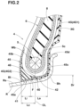
- FIG. 2 is a cross-sectional view of a bead portion of the pneumatic tire.
- FIG. 1 shows a pneumatic tire as an embodiment of the present disclosure which is under its normal state.
- the “normal state” of a tire means a state of the tire which is mounted on a normal wheel rim R, and inflated to a normal internal pressure, and loaded with no tire load.
- the “normal wheel rim” is a wheel rim specified for the tire by a standard included in a standardization system on which the tire is based, for example, the “normal wheel rim” in JATMA, “Design Rim” in TRA, and “Measuring Rim” in ETRTO.
- the “normal inner pressure” is air pressure specified for the tire by a standard included in a standardization system on which the tire is based, for example, the “maximum air pressure” in JATMA, maximum value listed in the “TIRE LOAD LIMITS AT VARIOUS COLD INFLATION PRESSURES” table in TRA, and “INFLATION PRESSURE” in ETRTO.
- the tire 1 comprises: a tread portion 2 having a pair of tread edges; a pair of axially spaced bead portions 4 each with a bead core 5 embedded therein; and a pair of sidewall portions 3 extending from the tread edges to the bead portions 4 .
- the tire 1 is provided with an inner liner 10 made of an air-impermeable rubber compound and disposed along the tire inner surface.
- FIG. 1 shows only a part of the tire 1 on one side of the tire equator C, the part on the other side has the same structure as the one side.
- the tire 1 is designed for racing cars used under severe running conditions, for example, running on a race circuit.
- the tire 1 may be formed as a pneumatic tire for passenger cars, light trucks and the like.
- the tire 1 is provided with a toroidal carcass 6 extending between the bead portions 4 through the tread portion 2 and the sidewall portions 3 , and a tread-reinforcing belt 7 disposed radially outside the carcass 6 in the tread portion 2 .
- the carcass 6 is composed of one or more carcass plies 6 A of carcass cords coated with a topping rubber.
- the carcass cords in each ply 6 A are arranged at an angle in a range from 80 to 90 degrees with respect to the tire equator C.
- an organic fiber cord is preferably used as the carcass cords.
- each of the bead portions 4 is provided with a bead apex 8 made of a hard rubber compound.
- the bead apex 8 extends radially outwardly from the bead core 5 between the turnup portion 6 b and the main portion 6 a.
- the belt 7 is composed of a plurality of belt plies, in this embodiment, only two cross plies 7 A and 7 B, and each ply 7 A, 7 B is made of parallel steel cords arranged at an angle in a range from 15 to 40 degrees with respect to the tire equator C. Such belt 7 increases the stiffness of the tread portion 2 .
- the tread portion 2 is further provided with a band 9 on the radially outside of the belt 7 .
- the band 9 is composed of at least one ply of a cord or cords arranged at an angle of at most 5 degrees with respect to the tire circumferential direction in order to provide tight hoop effect for the carcass 6 .
- an organic fiber cord is preferably used.
- the band 9 has a so-called jointless structure in which the band cord or cords are spirally wound in the tire circumferential direction plural times.
- the band 9 is composed of
- the tread portion 2 is provided with a tread rubber 2 G on the radially outside of the band 9 in the present embodiment.
- the tread rubber 2 G is disposed to form at least the tire tread or the radially outer surface of the tread portion 2 .
- a sidewall rubber 3 G is disposed axially outside the carcass 6 .
- the sidewall rubber 3 G is made of a relatively soft rubber compound.
- the sidewall rubber 3 G extends in the tire radial direction along the carcass 6 , and the radially outer end thereof is spliced to the tread rubber 2 G, and the radially inner end thereof is extended to the bead portion 4 , as detailed later.
- the bead portion 4 has a bottom surface 40 which comes into contact with a bead seat Rs of a wheel rim R when the tire 1 is mounted thereon.
- the bead seat Rs means a portion, which extends axially inwardly from a position in the rim width direction corresponding to the rim diameter Dr as shown in FIG. 2 , and which supports the bead portion 4 from the inside in the tire radial direction.
- the bead bottom surface 40 is made up of an axially inner region 41 including the bead toe Bt, and an axially outer region 42 including the bead heel Bh.
- the bead toe Bt means the axially innermost end of the bead bottom surface 40 .
- the bead heel Bh means the position on the bead bottom surface 40 corresponding to the rim diameter Dr.
- the axially inner region 41 is formed by a canvas chafer 45 .
- the axially outer region 42 is formed by the sidewall rubber 3 G extended radially inwardly from the sidewall portion 3 .
- the canvas chafer 45 is a rubberized canvas, and provides an excellent resistance to external injury to the bead bottom especially bead toe as compared with a so-called rubber chafer made of rubber alone.
- the axially inner region 41 of the bead bottom surface 40 is formed by the canvas chafer 45 , therefore, the damage to the bead toe Bt at the time when the tire is mounted on a wheel rim or the like can be suppressed. Therefore, in the tire 1 of the present embodiment, the deterioration of the air sealing effect due to the damage of the bead toe Bt can be suppressed.
- the canvas chafer 45 tends to have a smaller contact area with the bead seat Rs of the wheel rim R because the canvas is partially exposed or almost exposed and the amount of deformation of the canvas chafer 45 is small.
- the sidewall rubber 3 G which is made of a relatively soft rubber compound, is used to form the axially outer region 42 of the bead bottom surface 40 .
- the axially outer region 42 of the bead bottom surface 40 becomes in close contact with the bead seat Rs of the wheel rim R owing to a compression deformation of the relatively soft sidewall rubber 3 G, and the contact area with the bead seat Rs is relatively increased.
- the coefficient of friction of rubber is pressure-dependent.
- the sidewall rubber 3 G positioned at the bead bottom surface 40 has the increased contact area with the bead seat Rs and uniform pressure distribution, and increases the coefficient of friction between the bead bottom surface 40 and the bead seat Rs to generate a large frictional force.
- the axially inner region 41 of the bead bottom surface 40 is provided with the canvas chafer 45 having an excellent resistance to external injury
- the axially outer region 42 of the bead bottom surface 40 is provided with the sidewall rubber 3 G capable of generating a large frictional force between the sidewall rubber 3 G and the bead seat Rs.
- the tire 1 since the sidewall rubber 3 G is extended to the axially outer region 42 , it is not necessary to use an additional rubber member for solving the above-mentioned problem. Therefore, the tire 1 can be manufactured without increasing the manufacturing process and the number of component parts.
- the dimension Li in the tire axial direction of the axially inner region 41 is not less than 2 mm, more preferably not less than 3 mm in order to more effectively derive the above-mentioned effect of suppressing the tire/rim slippage under severe running conditions while suppressing damage to the bead toe Bt at the time when the tire is mounted on the wheel rim.
- the axial dimension Li of the axially inner region 41 is set to be not more than Lc+0.5 Wb, more preferably less than Lc+0.5 Wb, wherein
- the sidewall rubber 3 G exists in a position radially inside the bead core 5 (specifically, a region, of which axial extent corresponds to the axial dimension Wb of the bead core 5 , and which is positioned exactly radially inside the bead core 5 ) since the contact pressure with the bead seat Rs of the wheel rim R is high in such position.
- the above-mentioned boundary F between the canvas chafer 45 and the sidewall rubber 3 G is preferably located in the position radially inside the bead core 5 .
- the sidewall rubber 3 G exists at a position exactly radially inside the centroid 5 c of the bead core 5 , since the contact pressure with the bead seat Rs of the wheel rim R becomes highest at this position. As a result, the effect of suppressing the tire/rim slippage is further enhanced.
- the canvas chafer 45 in this example comprises:
- a second portion 45 b extending radially outwardly from the bead toe Bt along the tire inner surface facing the tire cavity.
- Such canvas chafer 45 can reinforce the bead toe Bt from the radially inside and the axially inside, therefore, the damage to the bead toe Bt when the tire is mounted on the wheel rim is more reliably prevented.
- the canvas chafer 45 may comprise a third portion 45 c overlapped with the sidewall rubber on the radially outside thereof in the axially outer region 42 .
- the third portion 45 c is continuous from the first portion 45 a .
- the third portion 45 c effectively transmits the tightening force of the bead core 5 to the sidewall rubber 3 G located radially inside the bead core 5 , which helps to further increase the frictional force between the axially outer region 42 and the bead seat Rs.
- the canvas chafer 45 may further comprise a fourth portion 45 d continuous from the third portion 45 c and extending radially outward.
- the fourth portion 45 d in this example extends in the tire radial direction between the sidewall rubber 3 G and the carcass 6 .
- Such fourth portion 45 d can increase the bending rigidity of the bead portion 4 , and also allows the sidewall rubber 3 G to be brought into close contact with the rim flange. Thus, the tire/rim slippage can be further suppressed.
- the sidewall rubber 3 G has a complex elastic modulus of not more than 10 MPa, more preferably not more than 8 MPa, still more preferably not more than 6 MPa.
- Such sidewall rubber 3 G at the bead bottom surface 40 can be sufficiently compressed and deformed on the bead seat Rs when the tire is mounted on the wheel rim, and a high frictional force occurs between the bead bottom surface 40 and the bead seat Rs. Therefore, the tire/rim slippage can be suppressed more effectively.
- the complex elastic modulus of the sidewall rubber 3 G is not less than 2 MPa, more preferably not less than 3 MPa, still more preferably not less than 4 MPa.
- the complex elastic modulus is measured under the following conditions (temperature 100 degrees C., initial strain 5%, dynamic strain 1%, frequency 10 Hz, measuring mode tensile, and sample dimensions 20 ⁇ 4 ⁇ 1 mm (length ⁇ width ⁇ thickness)), using a dynamic viscoelasticity measuring device (EPLEXOR manufactured by GABO).
- the measuring sample is took out from the sidewall rubber 3 G so that the length direction of the sample coincides the tire circumferential direction.
- the thickness of the sidewall rubber 3 G is preferably set in a range from 0.5 to 2.0 mm.
- the thickness of the sidewall rubber 3 G is preferably set in a range from 0.5 to 2.0 mm.
- the thickness of the sidewall rubber 3 G is measured in the direction orthogonal to the bead bottom surface 40 .
- Each of the bead portions 4 may be provided with a clinch rubber 4 G having a complex elastic modulus larger than that of the sidewall rubber 3 G.
- the clinch rubber 4 G may include a first clinch rubber 4 G 1 disposed in the bead portion 4 between the sidewall rubber 3 G and the carcass 6 .
- the first clinch rubber 4 G 1 is arranged from the sidewall portion 3 to the bead portion 4 in order to increase the bending rigidity of such portions of the tire. Therefore, the tire 1 can exhibit excellent steering stability for a racing car tire.
- the clinch rubber 4 G may include a second clinch rubber 4 G 2 disposed on the radially outside of the canvas chafer 45 in the axially inner region 41 .
- the second clinch rubber 4 G 2 is arranged adjacently to the first portion 45 a and the second portion 45 b of the canvas chafer 45 .
- Such second clinch rubber 4 G 2 effectively reinforces the bead portion 4 in the vicinity of the bead toe Bt and prevents damage to the bead toe Bt.
- the complex elastic modulus of the clinch rubber 4 G is not particularly limited as long as it is larger than the complex elastic modulus of the sidewall rubber 3 G.
- the ratio (E*s/E*c) of the complex elastic modulus E*s of the sidewall rubber 3 G to the complex elastic modulus E*c of the clinch rubber 4 G is preferably set to be not more than 0.20.
- the ratio (E*s/E*c) becomes excessively small, it becomes difficult to achieve both the high-speed steering stability and the effect of preventing tire/rim slippage. From this point of view, the ratio (E*s/E*c) is preferably not less than 0.10. [Compression]
- the compression of the bead bottom is 10% to 16% in a portion 46 radially inside the bead core 5 .
- the compression of the bead bottom is determined by measuring the thickness in the tire radial direction from the bead core 5 to the bead bottom surface 40 before and after the tire is mounted on a wheel rim, and then dividing the thickness after the tire is mounted by the thickness before the tire is mounted.
- the above-mentioned thickness may be measured on a straight line CL extending in parallel with the tire radial direction through the centroid 5 c of the bead core 5 .
- the frictional force can be maximized by optimizing the pressure in the above-mentioned portion 46 radially inside the bead core 5 .
- the frictional force between the bead bottom surface 40 and the bead seat Rs becomes maximized, and a higher effect of suppressing the tire/rim slippage can be obtained.
- pneumatic tires for racing cars were experimentally manufactured as test tires (Working example tire Ex., and Comparative example tires Ref.1 and Ref.2) and tested for the bead-toe damage resistance, steering stability, and tire/rim slippage resistance.
- the comparative example tire Ref.1 was the same as the working example tire except that the entire bead bottom surface was formed by a canvas chafer
- the comparative example tire Ref.2 was the same as the working example tire except that the entire bead bottom surface was formed by a rubber chafer.
- test tire was mounted on a wheel rim of size 18 ⁇ 13.0 J without applying a rim slippage prevention agent, and the tire was inflated to 180 kPa.
- Such tire-rim assemblies were mounted on all wheels of a racing car (FIA GT3 category machine). Then, a professional driver run the racing car on a racing circuit course with full throttle open, and evaluated the steering stability.
- pneumatic tires (Working examples Ex.1 to Ex.8) according to the present disclosure were prepared by changing specifications as shown in Table 2, and subjected to the same tests as described above. The test results are shown in Table 2.
- tire (Ex.9 to Ex.11) according to the present disclosure were prepared by changing the compression of the bead bottom and subjected to the same tests.
- the test results are shown in Table 3.
- the present disclosure is as follows.
- a pneumatic tire comprising: a tread portion; a pair of sidewall portions; a pair of bead portions each with a bead core embedded therein; a toroidal carcass extending between the bead portions; and a sidewall rubber disposed axially outside the carcass in each of the sidewall portions, wherein
Landscapes
- Engineering & Computer Science (AREA)
- Mechanical Engineering (AREA)
- Tires In General (AREA)
Applications Claiming Priority (2)
| Application Number | Priority Date | Filing Date | Title |
|---|---|---|---|
| JP2021052199A JP2022149871A (ja) | 2021-03-25 | 2021-03-25 | 空気入りタイヤ |
| JP2021-052199 | 2021-03-25 |
Publications (2)
| Publication Number | Publication Date |
|---|---|
| US20220305849A1 US20220305849A1 (en) | 2022-09-29 |
| US11752808B2 true US11752808B2 (en) | 2023-09-12 |
Family
ID=80685165
Family Applications (1)
| Application Number | Title | Priority Date | Filing Date |
|---|---|---|---|
| US17/694,000 Active US11752808B2 (en) | 2021-03-25 | 2022-03-14 | Pneumatic tire |
Country Status (4)
| Country | Link |
|---|---|
| US (1) | US11752808B2 (ja) |
| EP (1) | EP4063147A1 (ja) |
| JP (1) | JP2022149871A (ja) |
| CN (1) | CN115122833A (ja) |
Citations (10)
| Publication number | Priority date | Publication date | Assignee | Title |
|---|---|---|---|---|
| US5107915A (en) * | 1989-10-11 | 1992-04-28 | The Yokohama Rubber Co., Ltd. | Pneumatic tire for passenger car |
| JP2684202B2 (ja) * | 1988-11-01 | 1997-12-03 | 住友ゴム工業 株式会社 | 自動車用タイヤ |
| JP2005193868A (ja) * | 2004-01-09 | 2005-07-21 | Sumitomo Rubber Ind Ltd | 乗用車用ラジアルタイヤ |
| US20100032071A1 (en) * | 2008-08-07 | 2010-02-11 | Tatsuya Miyazaki | Tire |
| EP2910391A1 (en) | 2012-11-12 | 2015-08-26 | Sumitomo Rubber Industries, Ltd. | Pneumatic tire |
| JP2015199465A (ja) | 2014-04-10 | 2015-11-12 | 住友ゴム工業株式会社 | 空気入りタイヤ |
| EP3156256A1 (en) | 2015-10-14 | 2017-04-19 | Sumitomo Rubber Industries Limited | Pneumatic tire |
| EP3196055A1 (en) | 2014-09-04 | 2017-07-26 | Sumitomo Rubber Industries, Ltd. | Pneumatic tire |
| US20200023690A1 (en) * | 2018-07-17 | 2020-01-23 | Sumitomo Rubber Industries, Ltd. | Pneumatic tyre |
| EP3936353A1 (en) | 2020-07-06 | 2022-01-12 | Sumitomo Rubber Industries, Ltd. | Pneumatic tire |
-
2021
- 2021-03-25 JP JP2021052199A patent/JP2022149871A/ja active Pending
-
2022
- 2022-02-28 CN CN202210189731.XA patent/CN115122833A/zh active Pending
- 2022-03-10 EP EP22161280.7A patent/EP4063147A1/en active Pending
- 2022-03-14 US US17/694,000 patent/US11752808B2/en active Active
Patent Citations (11)
| Publication number | Priority date | Publication date | Assignee | Title |
|---|---|---|---|---|
| JP2684202B2 (ja) * | 1988-11-01 | 1997-12-03 | 住友ゴム工業 株式会社 | 自動車用タイヤ |
| US5107915A (en) * | 1989-10-11 | 1992-04-28 | The Yokohama Rubber Co., Ltd. | Pneumatic tire for passenger car |
| JP2005193868A (ja) * | 2004-01-09 | 2005-07-21 | Sumitomo Rubber Ind Ltd | 乗用車用ラジアルタイヤ |
| US20100032071A1 (en) * | 2008-08-07 | 2010-02-11 | Tatsuya Miyazaki | Tire |
| EP2910391A1 (en) | 2012-11-12 | 2015-08-26 | Sumitomo Rubber Industries, Ltd. | Pneumatic tire |
| US20150283865A1 (en) * | 2012-11-12 | 2015-10-08 | Sumitomo Rubber Industries, Ltd. | Pneumatic tire |
| JP2015199465A (ja) | 2014-04-10 | 2015-11-12 | 住友ゴム工業株式会社 | 空気入りタイヤ |
| EP3196055A1 (en) | 2014-09-04 | 2017-07-26 | Sumitomo Rubber Industries, Ltd. | Pneumatic tire |
| EP3156256A1 (en) | 2015-10-14 | 2017-04-19 | Sumitomo Rubber Industries Limited | Pneumatic tire |
| US20200023690A1 (en) * | 2018-07-17 | 2020-01-23 | Sumitomo Rubber Industries, Ltd. | Pneumatic tyre |
| EP3936353A1 (en) | 2020-07-06 | 2022-01-12 | Sumitomo Rubber Industries, Ltd. | Pneumatic tire |
Non-Patent Citations (3)
| Title |
|---|
| Extended European Search Report for European Application No. 22161280.7, dated Aug. 10, 2022. |
| Machine Translation: JP-2005193868-A, Yugawa N, (Year: 2023). * |
| Machine Translation: JP-2684202-B2, Iwamura K, (Year: 2023). * |
Also Published As
| Publication number | Publication date |
|---|---|
| JP2022149871A (ja) | 2022-10-07 |
| US20220305849A1 (en) | 2022-09-29 |
| EP4063147A1 (en) | 2022-09-28 |
| CN115122833A (zh) | 2022-09-30 |
Similar Documents
| Publication | Publication Date | Title |
|---|---|---|
| US11142027B2 (en) | Pneumatic tire | |
| US20200023691A1 (en) | Pneumatic tire | |
| JP6461633B2 (ja) | タイヤ | |
| US11254167B2 (en) | Pneumatic tyre | |
| US11964517B2 (en) | Pneumatic tire | |
| US10688835B2 (en) | Run-flat tire | |
| US10124630B2 (en) | Tire | |
| US20200016934A1 (en) | Heavy duty pneumatic tire | |
| EP3235664B1 (en) | Pneumatic tire | |
| EP3636454A1 (en) | Tire | |
| US11752808B2 (en) | Pneumatic tire | |
| CN108944272B (zh) | 充气轮胎 | |
| JP4995541B2 (ja) | 空気入りタイヤ | |
| US20220203769A1 (en) | Tire | |
| US11554610B2 (en) | Pneumatic tire | |
| US20220212506A1 (en) | Pneumatic tire and manufacturing methods therefor | |
| US20220219497A1 (en) | Pneumatic tire | |
| JP7187882B2 (ja) | ランフラットタイヤ | |
| US11850892B2 (en) | Pneumatic tire | |
| US20230311584A1 (en) | Pneumatic tire | |
| EP3536522B1 (en) | Run flat tire | |
| US20230256779A1 (en) | Tire | |
| US20220009294A1 (en) | Pneumatic tire | |
| US10744826B2 (en) | Pneumatic tire | |
| JP2017121906A (ja) | 空気入りタイヤ |
Legal Events
| Date | Code | Title | Description |
|---|---|---|---|
| FEPP | Fee payment procedure |
Free format text: ENTITY STATUS SET TO UNDISCOUNTED (ORIGINAL EVENT CODE: BIG.); ENTITY STATUS OF PATENT OWNER: LARGE ENTITY |
|
| AS | Assignment |
Owner name: SUMITOMO RUBBER INDUSTRIES, LTD., JAPAN Free format text: ASSIGNMENT OF ASSIGNORS INTEREST;ASSIGNOR:SATO, YOHEI;REEL/FRAME:059366/0381 Effective date: 20220128 |
|
| STPP | Information on status: patent application and granting procedure in general |
Free format text: DOCKETED NEW CASE - READY FOR EXAMINATION |
|
| STPP | Information on status: patent application and granting procedure in general |
Free format text: NOTICE OF ALLOWANCE MAILED -- APPLICATION RECEIVED IN OFFICE OF PUBLICATIONS |
|
| STPP | Information on status: patent application and granting procedure in general |
Free format text: PUBLICATIONS -- ISSUE FEE PAYMENT VERIFIED |
|
| STCF | Information on status: patent grant |
Free format text: PATENTED CASE |