US11710837B2 - Fuel cell system including a separation membrane - Google Patents
Fuel cell system including a separation membrane Download PDFInfo
- Publication number
- US11710837B2 US11710837B2 US16/463,882 US201716463882A US11710837B2 US 11710837 B2 US11710837 B2 US 11710837B2 US 201716463882 A US201716463882 A US 201716463882A US 11710837 B2 US11710837 B2 US 11710837B2
- Authority
- US
- United States
- Prior art keywords
- fuel cell
- gas
- separation membrane
- water vapor
- channel
- Prior art date
- Legal status (The legal status is an assumption and is not a legal conclusion. Google has not performed a legal analysis and makes no representation as to the accuracy of the status listed.)
- Active, expires
Links
Images


Classifications
-
- H—ELECTRICITY
- H01—ELECTRIC ELEMENTS
- H01M—PROCESSES OR MEANS, e.g. BATTERIES, FOR THE DIRECT CONVERSION OF CHEMICAL ENERGY INTO ELECTRICAL ENERGY
- H01M8/00—Fuel cells; Manufacture thereof
- H01M8/04—Auxiliary arrangements, e.g. for control of pressure or for circulation of fluids
- H01M8/04298—Processes for controlling fuel cells or fuel cell systems
- H01M8/04694—Processes for controlling fuel cells or fuel cell systems characterised by variables to be controlled
-
- H—ELECTRICITY
- H01—ELECTRIC ELEMENTS
- H01M—PROCESSES OR MEANS, e.g. BATTERIES, FOR THE DIRECT CONVERSION OF CHEMICAL ENERGY INTO ELECTRICAL ENERGY
- H01M8/00—Fuel cells; Manufacture thereof
- H01M8/04—Auxiliary arrangements, e.g. for control of pressure or for circulation of fluids
- H01M8/04082—Arrangements for control of reactant parameters, e.g. pressure or concentration
- H01M8/04089—Arrangements for control of reactant parameters, e.g. pressure or concentration of gaseous reactants
- H01M8/04119—Arrangements for control of reactant parameters, e.g. pressure or concentration of gaseous reactants with simultaneous supply or evacuation of electrolyte; Humidifying or dehumidifying
- H01M8/04156—Arrangements for control of reactant parameters, e.g. pressure or concentration of gaseous reactants with simultaneous supply or evacuation of electrolyte; Humidifying or dehumidifying with product water removal
-
- H—ELECTRICITY
- H01—ELECTRIC ELEMENTS
- H01M—PROCESSES OR MEANS, e.g. BATTERIES, FOR THE DIRECT CONVERSION OF CHEMICAL ENERGY INTO ELECTRICAL ENERGY
- H01M8/00—Fuel cells; Manufacture thereof
- H01M8/24—Grouping of fuel cells, e.g. stacking of fuel cells
- H01M8/241—Grouping of fuel cells, e.g. stacking of fuel cells with solid or matrix-supported electrolytes
- H01M8/2425—High-temperature cells with solid electrolytes
-
- H—ELECTRICITY
- H01—ELECTRIC ELEMENTS
- H01M—PROCESSES OR MEANS, e.g. BATTERIES, FOR THE DIRECT CONVERSION OF CHEMICAL ENERGY INTO ELECTRICAL ENERGY
- H01M8/00—Fuel cells; Manufacture thereof
-
- H—ELECTRICITY
- H01—ELECTRIC ELEMENTS
- H01M—PROCESSES OR MEANS, e.g. BATTERIES, FOR THE DIRECT CONVERSION OF CHEMICAL ENERGY INTO ELECTRICAL ENERGY
- H01M8/00—Fuel cells; Manufacture thereof
- H01M8/02—Details
- H01M8/0202—Collectors; Separators, e.g. bipolar separators; Interconnectors
-
- H—ELECTRICITY
- H01—ELECTRIC ELEMENTS
- H01M—PROCESSES OR MEANS, e.g. BATTERIES, FOR THE DIRECT CONVERSION OF CHEMICAL ENERGY INTO ELECTRICAL ENERGY
- H01M8/00—Fuel cells; Manufacture thereof
- H01M8/04—Auxiliary arrangements, e.g. for control of pressure or for circulation of fluids
-
- H—ELECTRICITY
- H01—ELECTRIC ELEMENTS
- H01M—PROCESSES OR MEANS, e.g. BATTERIES, FOR THE DIRECT CONVERSION OF CHEMICAL ENERGY INTO ELECTRICAL ENERGY
- H01M8/00—Fuel cells; Manufacture thereof
- H01M8/04—Auxiliary arrangements, e.g. for control of pressure or for circulation of fluids
- H01M8/04007—Auxiliary arrangements, e.g. for control of pressure or for circulation of fluids related to heat exchange
- H01M8/04014—Heat exchange using gaseous fluids; Heat exchange by combustion of reactants
- H01M8/04022—Heating by combustion
-
- H—ELECTRICITY
- H01—ELECTRIC ELEMENTS
- H01M—PROCESSES OR MEANS, e.g. BATTERIES, FOR THE DIRECT CONVERSION OF CHEMICAL ENERGY INTO ELECTRICAL ENERGY
- H01M8/00—Fuel cells; Manufacture thereof
- H01M8/04—Auxiliary arrangements, e.g. for control of pressure or for circulation of fluids
- H01M8/04082—Arrangements for control of reactant parameters, e.g. pressure or concentration
- H01M8/04089—Arrangements for control of reactant parameters, e.g. pressure or concentration of gaseous reactants
- H01M8/04097—Arrangements for control of reactant parameters, e.g. pressure or concentration of gaseous reactants with recycling of the reactants
-
- H—ELECTRICITY
- H01—ELECTRIC ELEMENTS
- H01M—PROCESSES OR MEANS, e.g. BATTERIES, FOR THE DIRECT CONVERSION OF CHEMICAL ENERGY INTO ELECTRICAL ENERGY
- H01M8/00—Fuel cells; Manufacture thereof
- H01M8/04—Auxiliary arrangements, e.g. for control of pressure or for circulation of fluids
- H01M8/04082—Arrangements for control of reactant parameters, e.g. pressure or concentration
- H01M8/04201—Reactant storage and supply, e.g. means for feeding, pipes
- H01M8/04216—Reactant storage and supply, e.g. means for feeding, pipes characterised by the choice for a specific material, e.g. carbon, hydride, absorbent
-
- H—ELECTRICITY
- H01—ELECTRIC ELEMENTS
- H01M—PROCESSES OR MEANS, e.g. BATTERIES, FOR THE DIRECT CONVERSION OF CHEMICAL ENERGY INTO ELECTRICAL ENERGY
- H01M8/00—Fuel cells; Manufacture thereof
- H01M8/06—Combination of fuel cells with means for production of reactants or for treatment of residues
- H01M8/0606—Combination of fuel cells with means for production of reactants or for treatment of residues with means for production of gaseous reactants
- H01M8/0612—Combination of fuel cells with means for production of reactants or for treatment of residues with means for production of gaseous reactants from carbon-containing material
- H01M8/0618—Reforming processes, e.g. autothermal, partial oxidation or steam reforming
-
- H—ELECTRICITY
- H01—ELECTRIC ELEMENTS
- H01M—PROCESSES OR MEANS, e.g. BATTERIES, FOR THE DIRECT CONVERSION OF CHEMICAL ENERGY INTO ELECTRICAL ENERGY
- H01M8/00—Fuel cells; Manufacture thereof
- H01M8/06—Combination of fuel cells with means for production of reactants or for treatment of residues
- H01M8/0662—Treatment of gaseous reactants or gaseous residues, e.g. cleaning
- H01M8/0668—Removal of carbon monoxide or carbon dioxide
-
- H—ELECTRICITY
- H01—ELECTRIC ELEMENTS
- H01M—PROCESSES OR MEANS, e.g. BATTERIES, FOR THE DIRECT CONVERSION OF CHEMICAL ENERGY INTO ELECTRICAL ENERGY
- H01M8/00—Fuel cells; Manufacture thereof
- H01M8/06—Combination of fuel cells with means for production of reactants or for treatment of residues
- H01M8/0662—Treatment of gaseous reactants or gaseous residues, e.g. cleaning
- H01M8/0687—Reactant purification by the use of membranes or filters
-
- H—ELECTRICITY
- H01—ELECTRIC ELEMENTS
- H01M—PROCESSES OR MEANS, e.g. BATTERIES, FOR THE DIRECT CONVERSION OF CHEMICAL ENERGY INTO ELECTRICAL ENERGY
- H01M8/00—Fuel cells; Manufacture thereof
- H01M8/10—Fuel cells with solid electrolytes
- H01M8/12—Fuel cells with solid electrolytes operating at high temperature, e.g. with stabilised ZrO2 electrolyte
-
- H—ELECTRICITY
- H01—ELECTRIC ELEMENTS
- H01M—PROCESSES OR MEANS, e.g. BATTERIES, FOR THE DIRECT CONVERSION OF CHEMICAL ENERGY INTO ELECTRICAL ENERGY
- H01M8/00—Fuel cells; Manufacture thereof
- H01M8/24—Grouping of fuel cells, e.g. stacking of fuel cells
- H01M8/241—Grouping of fuel cells, e.g. stacking of fuel cells with solid or matrix-supported electrolytes
- H01M8/244—Grouping of fuel cells, e.g. stacking of fuel cells with solid or matrix-supported electrolytes with matrix-supported molten electrolyte
-
- H—ELECTRICITY
- H01—ELECTRIC ELEMENTS
- H01M—PROCESSES OR MEANS, e.g. BATTERIES, FOR THE DIRECT CONVERSION OF CHEMICAL ENERGY INTO ELECTRICAL ENERGY
- H01M8/00—Fuel cells; Manufacture thereof
- H01M8/24—Grouping of fuel cells, e.g. stacking of fuel cells
- H01M8/2457—Grouping of fuel cells, e.g. stacking of fuel cells with both reactants being gaseous or vaporised
-
- H—ELECTRICITY
- H01—ELECTRIC ELEMENTS
- H01M—PROCESSES OR MEANS, e.g. BATTERIES, FOR THE DIRECT CONVERSION OF CHEMICAL ENERGY INTO ELECTRICAL ENERGY
- H01M8/00—Fuel cells; Manufacture thereof
- H01M8/24—Grouping of fuel cells, e.g. stacking of fuel cells
- H01M8/249—Grouping of fuel cells, e.g. stacking of fuel cells comprising two or more groupings of fuel cells, e.g. modular assemblies
-
- H—ELECTRICITY
- H01—ELECTRIC ELEMENTS
- H01M—PROCESSES OR MEANS, e.g. BATTERIES, FOR THE DIRECT CONVERSION OF CHEMICAL ENERGY INTO ELECTRICAL ENERGY
- H01M8/00—Fuel cells; Manufacture thereof
- H01M8/10—Fuel cells with solid electrolytes
- H01M8/12—Fuel cells with solid electrolytes operating at high temperature, e.g. with stabilised ZrO2 electrolyte
- H01M2008/1293—Fuel cells with solid oxide electrolytes
-
- H—ELECTRICITY
- H01—ELECTRIC ELEMENTS
- H01M—PROCESSES OR MEANS, e.g. BATTERIES, FOR THE DIRECT CONVERSION OF CHEMICAL ENERGY INTO ELECTRICAL ENERGY
- H01M8/00—Fuel cells; Manufacture thereof
- H01M8/14—Fuel cells with fused electrolytes
- H01M2008/147—Fuel cells with molten carbonates
-
- Y—GENERAL TAGGING OF NEW TECHNOLOGICAL DEVELOPMENTS; GENERAL TAGGING OF CROSS-SECTIONAL TECHNOLOGIES SPANNING OVER SEVERAL SECTIONS OF THE IPC; TECHNICAL SUBJECTS COVERED BY FORMER USPC CROSS-REFERENCE ART COLLECTIONS [XRACs] AND DIGESTS
- Y02—TECHNOLOGIES OR APPLICATIONS FOR MITIGATION OR ADAPTATION AGAINST CLIMATE CHANGE
- Y02E—REDUCTION OF GREENHOUSE GAS [GHG] EMISSIONS, RELATED TO ENERGY GENERATION, TRANSMISSION OR DISTRIBUTION
- Y02E60/00—Enabling technologies; Technologies with a potential or indirect contribution to GHG emissions mitigation
- Y02E60/30—Hydrogen technology
- Y02E60/50—Fuel cells
-
- Y—GENERAL TAGGING OF NEW TECHNOLOGICAL DEVELOPMENTS; GENERAL TAGGING OF CROSS-SECTIONAL TECHNOLOGIES SPANNING OVER SEVERAL SECTIONS OF THE IPC; TECHNICAL SUBJECTS COVERED BY FORMER USPC CROSS-REFERENCE ART COLLECTIONS [XRACs] AND DIGESTS
- Y02—TECHNOLOGIES OR APPLICATIONS FOR MITIGATION OR ADAPTATION AGAINST CLIMATE CHANGE
- Y02P—CLIMATE CHANGE MITIGATION TECHNOLOGIES IN THE PRODUCTION OR PROCESSING OF GOODS
- Y02P70/00—Climate change mitigation technologies in the production process for final industrial or consumer products
- Y02P70/50—Manufacturing or production processes characterised by the final manufactured product
Definitions
- the present invention relates to a fuel cell system.
- a fuel cell power generation system that includes a first fuel cell stack; a first carbon dioxide removing apparatus; and a second fuel cell stack, in which a sub-nano ceramic membrane filter is used as the first carbon dioxide removal apparatus for removing carbon dioxide in the exhaust gas supplied to the second fuel cell stack (see, for example, Patent Document 1).
- a multi-stage fuel cell system including a first fuel cell, a water vapor separation membrane, and a second fuel cell, by which water vapor is removed in a gas state from an off gas including unreacted fuel gas discharged from the first fuel cell, by the water vapor separation membrane, and power generation is carried out with the second fuel cell using a regenerated fuel gas obtained by removing water vapor from the off gas (see, for example, Patent Document 2).
- a circulation fuel cell system including a fuel cell; a water vapor separation membrane; and a regenerated fuel gas channel, by which water vapor is removed in a gas state from an off gas including unreacted fuel gas discharged from the fuel cell, by the water vapor separation membrane, a regenerated fuel gas obtained by removing water vapor from the off gas is supplied to the fuel cell through the regenerated fuel gas channel, and power generation is carried out (see, for example, Patent Document 3).
- a circulation fuel cell system that removes carbon dioxide or water vapor in an anode exhaust gas using a separation membrane.
- a circulation fuel cell system employing a method of removing carbon dioxide or water vapor in an anode exhaust gas by supplying air to the permeation side of the separation membrane, or a method of reducing the pressure on the permeation side of the separation membrane using a vacuum pump, and thereby removing carbon dioxide or water vapor in the anode exhaust gas, has been suggested (see, for example, Patent Document 4).
- Patent Document 1 Japanese Patent Application Laid-Open (JP-A) No. 2015-201266
- Patent Document 2 JP-A No. 2016-115495
- Patent Document 3 JP-A No. 2016-115496
- Patent Document 4 US Patent Application Publication No. 2013/0108936
- Patent Documents 1 to 4 It is described in Patent Documents 1 to 4 that the power generation efficiency of the system is increased by removing at least one of carbon dioxide or water vapor in the anode exhaust gas using a separation membrane and thus increasing the concentration of hydrogen or carbon monoxide as a fuel.
- separation membranes it is difficult not to allow 100% permeation of hydrogen, and some of hydrogen included in the anode exhaust gas permeates through the membrane. Therefore, the amount of fuel that can be reutilized is reduced by permeation of hydrogen, and there is a risk that the power generation efficiency of the system may be lowered.
- nothing is considered in this regard in Patent Documents 1 to 4.
- the power generation efficiency of the whole system is increased by setting the ratio between the permeability of at least one of carbon dioxide or water vapor and the permeability of hydrogen (permeability coefficient ratio) for the separation membrane to an appropriate range.
- a fuel cell system comprising: a first fuel cell performing power generation using a fuel gas; a separation membrane separating at least one of carbon dioxide or water vapor from an anode off gas discharged from the first fuel cell, the anode off gas including an unreacted portion of the fuel gas; a second fuel cell disposed in the downstream of the separation membrane and performing power generation using the anode off gas, the anode off gas having at least one of carbon dioxide or water vapor separated therefrom; and a distribution channel disposed on a permeation side of the separation membrane and distributing any of the following: a raw material gas serving as the fuel gas to be used for the power generation of the first fuel cell, a cathode gas including oxygen to be used for the power generation of the first fuel cell, an anode off gas discharged from the second fuel cell, a cathode off gas discharged from the first fuel cell and to be supplied to the second fuel cell, or a cathode off gas discharged from the second fuel cell, in which the at least one of
- the fuel cell system according to the present embodiment is a multi-stage type fuel cell system including a first fuel cell and a second fuel cell, the fuel utilization rate is increased compared to a circulation type fuel cell system, and high power generation efficiency can be obtained.
- the distribution channel having any one of the above-mentioned gases distributed therein, at least one of carbon dioxide or water vapor thus separated circulates in the distribution channel together with any one of the above-mentioned gases that circulates in the distribution channel. Therefore, separation of at least one of carbon dioxide or water vapor can be promoted without separately providing a channel for supplying a sweep gas such as air to the permeation side of the separation membrane, and an air blower or a reduced pressure pump. Therefore, the overall power generation efficiency of the system can be increased while the production cost is reduced, and since the system is simplified, reliability of the system is enhanced.
- the concentration of fuel gas such as hydrogen or carbon monoxide is increased, and thus the power generation efficiency of the system can be enhanced.
- the concentration of fuel gas such as hydrogen or carbon monoxide
- the power generation efficiency of the system may be decreased by reduction of hydrogen as a fuel gas.
- At least one of the permeability coefficient ratio ⁇ 1 (P CO2 /P H2 ) or the permeability coefficient ratio ⁇ 2 (P H2O /P H2 ) is 30 or higher. Therefore, the influence of the effect of increasing the power generation efficiency of the system caused by at least one of carbon dioxide or water vapor permeating through the separation membrane becomes greater than the influence of the decrease in the power generation efficiency of the system caused by hydrogen permeating through the separation membrane, and the overall power generation efficiency of the system is excellent.
- a fuel cell system comprising: a fuel cell performing power generation using a fuel gas; a separation membrane separating at least one of carbon dioxide or water vapor from an anode off gas discharged from the fuel cell, the anode off gas including an unreacted portion of the fuel gas; an off gas circulation channel disposed in the downstream of the separation membrane and supplying the anode off gas to the fuel cell, the anode off gas having at least one of carbon dioxide or water vapor separated therefrom; and a distribution channel disposed on a permeation side of the separation membrane and distributing any of the following: a raw material gas serving as the fuel gas to be used for power generation of the fuel cell, a cathode gas including oxygen to be used for power generation of the fuel cell, or a cathode off gas discharged from the fuel cell, in which at least one of permeability coefficient ratio ⁇ 1 (P CO2 /P H2 ) of the separation membrane or permeability coefficient ratio ⁇ 2 (P H2O /P H2 ) of the
- the fuel cell system according to the present embodiment is a circulation type fuel cell system supplying an anode off gas having at least one of carbon dioxide or water vapor separated therefrom, and even with such a system, the fuel utilization rate is increased, and high power generation efficiency can be obtained.
- the fuel cell system according to the present embodiment can promote separation of at least one of carbon dioxide or water vapor, without separately providing a channel for supplying a sweep gas such as air to the permeation side of the separation membrane, and an air blower or a reduced pressure, similarly to the fuel cell system described above. Therefore, the overall power generation efficiency of the system can be increased while the production cost is reduced, and since the system is simplified, reliability of the system is enhanced.
- At least one of the permeability coefficient ratio ⁇ 1 (P CO2 /P H2 ) or the permeability coefficient ratio ⁇ 2 (P H2O /P H2 ) is 30 or higher. Therefore, the influence of the effect of increasing the power generation efficiency of the system caused by at least one of carbon dioxide or water vapor permeating through the separation membrane becomes greater than the influence of the decrease of the power generation efficiency of the system of hydrogen permeating through the separation membrane, and the overall power generation efficiency of the system is excellent.
- ⁇ 3> The fuel cell system according to ⁇ 1> or ⁇ 2>, further comprising a reformer, in which the reformer includes a reforming unit for reforming the raw material gas and thereby producing the fuel gas; and a combustion unit for heating the reforming unit by a combustion reaction.
- the fuel cell system according to the present embodiment further comprises a reformer that reforms a raw material gas and thereby producing a fuel gas, and the second fuel cell or the fuel cell performs power generation using a fuel gas produced by the reformer.
- ⁇ 4> The fuel cell system according to ⁇ 3>, further comprising an exhaust channel for distributing an exhaust gas discharged from the combustion unit, in which the exhaust channel is disposed on the permeation side of the separation membrane instead of the distribution channel.
- an exhaust channel is disposed on the permeation side of the separation membrane instead of the distribution channel, and at least one of carbon dioxide or water vapor separated by the separation membrane circulates in the exhaust channel together with an exhaust gas circulating in the exhaust channel. Therefore, separation of at least one of carbon dioxide or water vapor can be promoted without separately providing a channel for supplying a sweep gas such as air to the permeation side of the separation membrane, and an air blower or a reduced pressure pump. Therefore, the overall power generation efficiency of the system can be increased while the production cost is reduced, and since the system is simplified, reliability of the system is enhanced.
- ⁇ 5> The fuel cell system according to ⁇ 3> or ⁇ 4>, further comprising a water vapor collecting means for collecting water vapor in the exhaust gas discharged from the combustion unit; and a water vapor supply channel for supplying the water vapor collected by the water vapor collecting means, to the reforming unit.
- the fuel cell system comprises a water vapor collecting means for collecting water vapor included in the exhaust gas, for example, a condenser that collects water vapor by condensing the water vapor, and the water vapor collected by the water vapor collecting means is supplied to the reforming unit and is used for steam reforming of the raw material gas. Therefore, establishment of water independence, by which supplying of water vapor or reforming water from the outside becomes unnecessary, or reduction of the amount of supply of water vapor or reforming water from the outside, is enabled.
- ⁇ 6> The fuel cell system according to any one of ⁇ 1> to ⁇ 3>, further comprising a channel for distributing at least one of water vapor or carbon dioxide to be used at the time of producing the fuel gas by reforming the raw material gas, in which the channel is disposed on the permeation side of the separation membrane instead of the distribution channel.
- a channel for distributing at least one of water vapor or carbon dioxide is disposed on the permeation side of the separation membrane instead of the distribution channel, and at least one of carbon dioxide or water vapor separated by the separation membrane is used for reforming of the raw material gas together with the gas that circulates in the channel. Therefore, separation of at least one of carbon dioxide or water vapor can be promoted without separately providing a channel for supplying a sweep gas such as air to the permeation side of the separation membrane, and an air blower or a reduced pressure pump. Therefore, the overall power generation efficiency of the system can be increased while the production cost is reduced, and since the system is simplified, reliability of the system is enhanced.
- ⁇ 7> The fuel cell system according to any one of ⁇ 1> to ⁇ 6>, in which at least one of permeability coefficient ratio ⁇ 1 (P CO2 /P CO ) of the separation membrane or permeability coefficient ratio ⁇ 2 (P H2O /P CO ) of the separation membrane is 6 or higher.
- At least one of the permeability coefficient ratio ⁇ 1 (P CO2 /P CO ) or the permeability coefficient ratio ⁇ 2 (P H2O /P CO ) is 6 or higher. Therefore, the influence of the effect of increasing the power generation efficiency of the system caused by at least one of carbon dioxide or water vapor permeating through the separation membrane becomes greater than the influence of the decrease of the power generation efficiency of the system caused by carbon monoxide permeating through the separation membrane, and the overall power generation efficiency of the system is excellent.
- ⁇ 8> The fuel cell system according to any one of ⁇ 1> to ⁇ 7>, in which at least one of the permeability coefficient ratio ⁇ 1 (P CO2 /P H2 ) of the separation membrane or the permeability coefficient ratio ⁇ 2 (P H2O /P H2 ) of the separation membrane is 60 or higher.
- the influence of the effect of increasing the power generation efficiency of the system caused by at least one of carbon dioxide or water vapor permeating through the separation membrane becomes greater than the influence of the decrease of the power generation efficiency of the system caused by hydrogen permeating through the separation membrane, and the overall power generation efficiency of the system is superior.
- a fuel cell system having excellent overall power generation efficiency of the system can be provided by adjusting the ratio between the permeability of at least one of carbon dioxide or water vapor and the permeability of hydrogen in the separation membrane to an appropriate range.
- FIG. 1 is an outline configuration diagram illustrating a fuel cell system according to a first embodiment.
- FIG. 2 is an outline configuration diagram illustrating a fuel cell system according to a second embodiment.
- FIG. 3 is an outline configuration diagram illustrating a fuel cell system according to a third embodiment.
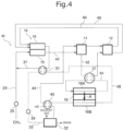
- FIG. 4 is an outline configuration diagram illustrating a fuel cell system according to a fourth embodiment.
- FIG. 5 is an outline configuration diagram illustrating a fuel cell system according to a fifth embodiment.
- FIG. 6 is an outline configuration diagram illustrating a fuel cell system according to a sixth embodiment.
- FIG. 7 is an outline configuration diagram illustrating a fuel cell system according to a seventh embodiment.
- FIG. 8 is an outline configuration diagram illustrating a fuel cell system according to an eighth embodiment.
- FIG. 9 is an outline configuration diagram illustrating a fuel cell system according to a ninth embodiment.
- FIG. 10 is an outline configuration diagram illustrating a fuel cell system according to a tenth embodiment.
- FIG. 11 is a graph showing the relationship between the permeability coefficient ratio ⁇ 1 and the system efficiency.
- FIG. 12 is a graph showing the relationship between the permeability coefficient ratio ⁇ 2 and the system efficiency.
- any numerical range indicated using an expression “from * to” represents a range in which numerical values described before and after the “* to” are included in the range as the lower limit value and the upper limit value thereof.
- FIG. 1 is an outline configuration diagram illustrating a fuel cell system according to a first embodiment.
- the fuel cell system 10 according to the first embodiment is a system comprising: a first fuel cell 11 for performing power generation using a fuel gas; a separation membrane 16 for separating at least one of carbon dioxide or water vapor from an anode off gas that is discharged from the first fuel cell 11 and includes unreacted fuel gas; a second fuel cell 12 disposed in the downstream of the separation membrane 16 for performing power generation using the anode off gas having at least one of carbon dioxide or water vapor separated therefrom; and an air supply channel 44 (distribution channel) disposed on the permeation side 16 B of the separation membrane 16 for distributing a cathode off gas discharged from the second fuel cell 12 .
- a separation membrane 16 for separating at least one of carbon dioxide or water vapor from an anode off gas that is discharged from the first fuel cell 11 and includes unreacted fuel gas
- a second fuel cell 12 disposed in the downstream of the separation membrane 16 for
- At least one of the permeability coefficient ratio ⁇ 1 (P CO2 /P H2 ) of the separation membrane 16 or the permeability coefficient ratio ⁇ 2 (P H2O /P H2 ) of the separation membrane 16 is 30 or higher.
- the fuel cell system 10 may comprise a reformer 14 including a reforming unit 19 that produces a fuel gas by reforming a raw material gas; and a combustion unit 18 that heats the reforming unit 19 by a combustion reaction.
- the fuel cell system 10 is a multi-stage type fuel cell system comprising a first fuel cell 11 and a second fuel cell 12 .
- a circulation type fuel cell system it is necessary to discharge some of the anode off gas discharged from the anode out of the circulation system in order to suppress an increase in the carbon dioxide concentration inside the circulation system; however, at that time, a portion of unreacted fuel gas is also discharged out of the circulation system. Therefore, there are limitations in increasing the fuel utilization rate.
- a multi-stage type fuel cell system the fuel gas included in the anode off gas discharged from the anode of the fuel cell of a previous stage (except for the fuel gas that has permeated through the separation membrane 16 ) is all supplied to the anode of the fuel cell of a subsequent stage. Therefore, a multi-stage type fuel cell system has an increased fuel utilization rate compared to a circulation type fuel cell system, and high power generation efficiency can be obtained.
- a separation membrane 16 by separating at least one of carbon dioxide or water vapor from an anode off gas discharged from the first fuel cell 11 and including unreacted fuel gas, using a separation membrane 16 , the concentration of the fuel gas such as hydrogen or carbon monoxide is increased, and thereby the power generation efficiency of the system can be enhanced.
- a separation membrane since hydrogen included in the anode off gas is separated together with at least one of carbon dioxide or water vapor, there is a risk that the power generation efficiency of the system may be decreased by reduction of hydrogen as a fuel gas.
- At least one of the permeability coefficient ratio ⁇ 1 (P CO2 /P H2 ) or the permeability coefficient ratio ⁇ 2 (P H2O /P H2 ) is 30 or higher. Therefore, the influence of the effect of increasing the power generation efficiency of the system caused by at least one of carbon dioxide or water vapor permeating through the separation membrane 16 becomes greater than the influence of the decrease in the power generation efficiency of the system caused by hydrogen permeating through the separation membrane 16 , and the overall power generation efficiency of the system is excellent.
- hydrogen and carbon monoxide include in the anode off gas can also be separated in trace amounts. Since hydrogen and carbon monoxide are highly reactive with oxygen, as hydrogen and carbon monoxide separated into the permeation side 16 B of the separation membrane 16 react with oxygen circulating on the permeation side 16 B, local temperature increase of the separation membrane 16 is likely to occur, and there is a risk that durability of the separation membrane 16 may deteriorate. Therefore, in order to maintain the durability of the separation membrane 16 suitably, it is preferable to supply a gas having a lower proportion of oxygen to the permeation side 16 B of the separation membrane 16 .
- the concentrations of carbon dioxide and water vapor included in the cathode off gas discharged from the second fuel cell 12 of the fuel cell system 10 are lower compared to, for example, the exhaust gas discharged from the combustion unit 18 . Therefore, in the fuel cell system 10 , the large water vapor partial pressure difference and the large carbon dioxide partial pressure difference between the supply side 16 A and the permeation side 16 B in the separation membrane 16 become large, compared to a fuel cell system 40 according to a fourth embodiment that will be described below, in which an exhaust gas (a gas including carbon dioxide and water vapor) is supplied to the permeation side 16 B of the separation membrane 16 , and separation of water vapor and carbon dioxide is promoted. Therefore, the fuel cell system 10 has superior power generation efficiency.
- an exhaust gas a gas including carbon dioxide and water vapor
- the fuel cell system 10 comprises a raw material gas supply channel 24 that supplies a raw material gas to a reformer 14 , and the raw material gas supply channel 24 is provided with a blower 25 for distributing the raw material gas.
- the raw material gas that circulates in the raw material gas supply channel 24 is not particularly limited as long as it is a gas that can be reformed, and an example may be a hydrocarbon fuel.
- the hydrocarbon fuel include natural gas, liquefied petroleum gas (LP gas), coal modified gas, and a lower hydrocarbon gas.
- the lower hydrocarbon gas include lower hydrocarbons having 4 or fewer carbon atoms, such as methane, ethane, ethylene, propane, or butane, and methane is particularly preferred.
- the hydrocarbon fuel may be a mixture of the above-mentioned lower hydrocarbon gases, or may be a gas obtained by mixing the above-mentioned lower hydrocarbon gases with a gas such as natural gas, town gas, or LP gas.
- the raw material gas supply channel 24 is connected to a water vapor supply channel 37 that will be described below, and the water vapor circulating in the water vapor supply channel 37 is supplied to the raw material gas supply channel 24 . Then, the water vapor supplied from the water vapor supply channel 37 is supplied to the reformer 14 together with the raw material gas. Meanwhile, from the viewpoint of preventing condensation of water vapor within the channel, the raw material gas supply channel 24 may be configured such that the raw material gas supply channel 24 is not connected to the water vapor supply channel 37 , and water vapor is directly supplied to the reformer 14 through the water vapor supply channel 37 .
- the fuel cell system 10 comprises a reformer 14 that produces a fuel gas by steam reforming a raw material gas.
- the reformer 14 is configured to include, for example, a combustion unit 18 where a burner or a combustion catalyst is disposed, and a reforming unit 19 including a reforming catalyst.
- the reforming unit 19 is connected to a raw material gas supply channel 24 on the upstream side and is connected to a fuel gas supply channel 42 on the downstream side. Therefore, a raw material gas such as methane is supplied to the reforming unit 19 through the raw material gas supply channel 24 , and after the raw material gas is steam reformed at the reforming unit 19 , a fuel gas thus produced is supplied to the first fuel cell 11 through the fuel gas supply channel 42 .
- the combustion unit 18 is connected to an air supply channel 44 and an off gas channel 46 on the upstream side and is connected to an exhaust channel 48 on the downstream side.
- the combustion unit 18 burns a mixed gas of a gas including unreacted oxygen (cathode off gas), which is discharged from the cathode side of the second fuel cell 12 and is supplied through the air supply channel 44 , and an anode off gas supplied through an off gas channel 46 , and heats a reforming catalyst in the reforming unit 19 .
- An exhaust gas from the combustion unit 18 circulates in the exhaust channel 48 .
- the reforming catalyst installed in the reforming unit 19 is not particularly limited as long as it serves as a catalyst for a steam reforming reaction; and, a steam reforming catalyst containing at least one of Ni, Rh, Ru, Ir, Pd, Pt, Re, Co, Fe, or Mo as a catalytic metal is preferred.
- the steam-carbon ratio S/C which is the ratio between the number of molecules S of water vapor per unit time supplied to the reforming unit 19 of the reformer 14 and the number of carbon atoms C of the raw material gas per unit time supplied to the reforming unit 19 of the reformer 14 , is preferably from 1.5 to 3.5, more preferably from 2.0 to 3.0, and even more preferably from 2.0 to 2.5.
- the steam-carbon ratio S/C is in this range, the raw material gas is efficiently steam-reformed, and a fuel gas including hydrogen and carbon monoxide is produced. Furthermore, carbon precipitation inside the fuel cell system 10 can be suppressed, and thus reliability of the fuel cell system 10 can be increased.
- the combustion unit 18 heats the reforming unit 19 to from 600° C. to 800° C., and more preferably heats the reforming unit 19 to from 600° C. to 700° C.
- the reformer is mounted in the outside of the first fuel cell, and the fuel cell system may be configured such that a raw material gas and water vapor are supplied directly to the first fuel cell, steam reforming (internal reforming) is performed inside the first fuel cell, and a fuel gas thus produced is used for the power generation at the first fuel cell.
- the first fuel cell is a high temperature type fuel cell
- the reaction temperature inside the fuel cell is a high temperature such as from 600° C. to 800° C., it is possible to perform steam reforming in the first fuel cell.
- An exhaust gas circulating in the exhaust channel 48 perform heat exchange at a heat exchanger 31 that plays a role of vaporizer, with reforming water that circulates in a reforming water supply channel 33 .
- the exhaust gas circulating in the exhaust channel 48 is supplied to a water tank 32 (water vapor collecting means, for example, a condenser) after being cooled, and the reforming water circulating in the reforming water supply channel 33 is supplied to the raw material gas supply channel 24 through the water vapor supply channel 37 after being vaporized.
- the water tank 32 is a container storing water that is obtained by condensing the water vapor included in the exhaust gas circulating in the exhaust channel 48 .
- the exhaust gas except for water vapor is discharged outside, and when a predetermined amount or more of water is stored, for example, the water is drain-discharged by overflow.
- the water tank 32 is connected to the reforming water supply channel 33 , and the reforming water supply channel 33 is provided with a reforming water pump 34 .
- the water stored in the water tank 32 is supplied as reforming water, by the reforming water pump 34 , to the heat exchanger 31 through the reforming water supply channel 33 .
- the configuration of separating water vapor from the exhaust gas circulating in the exhaust channel 48 is not limited to the water tank 32 , and for example, water vapor and gases other than water vapor may be separated using a separation membrane, or water vapor for steam reforming may be separated by adsorbing gases other than water vapor to an adsorbent.
- the heat exchanger 31 that performs heat exchange between the exhaust gas circulating in the exhaust channel 48 and the reforming water circulating in the reforming water supply channel 33 , it is also acceptable to provide a vaporizer that vaporizes reforming water by utilizing the heat discharged from at least one of the reforming unit 19 , the first fuel cell 11 , or the second fuel cell 12 .
- the air supply channel 44 is a channel in which a gas including oxygen (cathode gas), such as air, and a gas including unreacted oxygen (cathode off gas) circulate, and the air supply channel 44 is provided with a heat exchanger 22 .
- a gas including oxygen cathode gas
- cathode off gas a gas including unreacted oxygen
- the cathode off gas circulating in the air supply channel 44 on the downstream side of the second fuel cell 12 is cooled to a preferable temperature when at least one of carbon dioxide or water vapor is separated using a separation membrane 16 , and the air circulating in the air supply channel 44 on the upstream side of the first fuel cell 11 is heated to a temperature appropriate for the operation temperature of the first fuel cell 11 and then is supplied to the cathode of the first fuel cell 11 .
- the fuel cell system 10 comprises a first fuel cell 11 that performs power generation using a fuel gas supplied from a reformer 14 through a fuel gas supply channel 42 .
- the first fuel cell 11 may be, for example, a fuel battery cell including an air electrode (cathode), an electrolyte, and a fuel electrode (anode), or may be a fuel cell stack obtained by stacking a plurality of fuel battery cells.
- examples of the first fuel cell include high temperature type fuel cells that operate at about from 600° C. to 800° C., for example, a solid oxide fuel cell that operates at about from 700° C. to 800° C., and a molten carbonate fuel cell that operates at about from 600° C. to 700° C.
- the first fuel cell 11 is a solid oxide fuel cell
- air is supplied to the cathode (not illustrated in the diagram) of the first fuel cell 11 through the air supply channel 44 .
- a reaction represented by the following Formula (c) occurs, and at that time, oxygen ions move around the interior of a solid oxide electrolyte (not illustrated in the diagram).
- a fuel gas including hydrogen and carbon monoxide is supplied to the anode (not illustrated in the diagram) of the first fuel cell 11 through the fuel gas supply channel 42 .
- hydrogen and carbon monoxide receive electrons from the oxygen ions moving inside a solid oxide electrolyte at the interface between the anode and the solid oxide electrolyte, reactions represented by the following Formula (d) and Formula (e) occur.
- the first fuel cell 11 is a molten carbonate fuel cell
- a gas including oxygen and carbon dioxide is supplied to the cathode (not illustrated in the diagram) of the first fuel cell 11 through the air supply channel 44 .
- a reaction represented by the following Formula (f) occurs, and at that time, carbonate ions move around inside an electrolyte (not illustrated in the diagram).
- a fuel gas including hydrogen is supplied to the anode (not illustrated in the diagram) of the first fuel cell 11 through the fuel gas supply channel 42 .
- hydrogen receives electrons from the carbonate ions moving inside the electrolyte at the interface between the anode and the electrolyte, a reaction represented by the following Formula (g) occurs.
- the cathode off gas discharged from the cathode is supplied to the cathode (not illustrated in the diagram) of the second fuel cell 12 through the air supply channel 44 on the downstream side.
- an anode off gas that is discharged from the anode and includes unreacted fuel gas is supplied to the supply side 16 A of the separation membrane 16 through the off gas channel 52 .
- the anode off gas including unreacted fuel gas is a mixed gas including hydrogen, carbon monoxide, carbon dioxide, water vapor, and the like.
- a heat exchanger 21 is provided in the off gas channel 52 and the off gas channel 54 , and through this heat exchanger 21 , heat exchange is achieved between the anode off gas circulating in the off gas channel 52 and the anode off gas circulating in the off gas channel 54 and having at least one of carbon dioxide or water vapor separated therefrom.
- the anode off gas circulating in the off gas channel 52 is cooled to a preferable temperature at the time of separating at least one of carbon dioxide or water vapor using the separation membrane 16 , and the anode off gas circulating in the off gas channel 54 and having at least one of carbon dioxide or water vapor separated therefrom, are heated to a temperature appropriate for the operation temperature of the second fuel cell 12 . Therefore, the overall power generation efficiency and thermal efficiency of the system are further increased.
- the fuel cell system 10 comprises a separation membrane 16 that separates at least one of carbon dioxide or water vapor from an anode off gas discharged from the first fuel cell 11 and including unreacted fuel gas.
- the separation membrane 16 is a membrane in which at least one of the permeability coefficient ratio ⁇ 1 (P CO2 /P H2 ) or the permeability coefficient ratio ⁇ 2 (P H2O /P H2 ) satisfies 30 or higher.
- the anode off gas circulating in the off gas channel 52 is supplied to the supply side 16 A of the separation membrane 16 , and at least one of carbon dioxide or water vapor in the anode off gas passes through the separation membrane 16 in the direction of arrow A from the supply side 16 A to the permeation side 16 B.
- the anode off gas after having at least one of carbon dioxide or water vapor circulates in the off gas channel 54 from the supply side 16 A and is supplied to the second fuel cell 12 .
- At least one of carbon dioxide or water vapor thus separated is mixed with the cathode off gas discharged from the second fuel cell 12 and flowing in the permeation side 16 B, and the mixture circulates in the air supply channel 44 from the permeation side 16 B and is supplied to the combustion unit 18 of the reformer 14 . Therefore, the cathode off gas discharged from the second fuel cell 12 is utilized in a combustion reaction at the combustion unit 18 , and it is not necessary to supply oxygen separately to the combustion unit 18 .
- an air supply channel 44 for distributing the cathode off gas is provided on the permeation side of the separation membrane 16 , and thereby at least one of carbon dioxide or water vapor is caused to permeate to the permeation side of the separation membrane 16 . Therefore, it is not necessary to separately provide a channel for supplying oxygen to the permeation side of the separation membrane 16 , and an air blower or a reduced pressure pump, and the system is simplified.
- the fuel cell system 10 separation of at least one of carbon dioxide or water vapor is promoted along with simplification of the system. As a result, at least one of the water vapor concentration or the carbon dioxide concentration in the anode off gas supplied to the second fuel cell 12 can be made lower, and the power generation efficiency of the fuel cell system 10 can be further increased.
- the separation membrane 16 at least one of the permeability coefficient ratio ⁇ 1 (P CO2 /P H2 ) and the permeability coefficient ratio ⁇ 2 (P H2O /P H2 ) is 30 or higher, the influence of the effect of increasing the power generation efficiency of the system caused by at least one of carbon dioxide or water vapor permeating through the separation membrane 16 becomes greater than the influence of the decrease of the power generation efficiency of the system caused by hydrogen permeating through the separation membrane 16 , and the overall power generation efficiency of the system is excellent.
- the separation membrane 16 from the viewpoint of having superior overall power generation efficiency of the system, it is preferable that at least one of the permeability coefficient ratio ⁇ 1 (P CO2 /P H2 ) or the permeability coefficient ratio ⁇ 2 (P H2O /P H2 ) is 60 or higher, and it is more preferable that at least one of the permeability coefficient ratio ⁇ 1 (P CO2 /P H2 ) or the permeability coefficient ratio ⁇ 2 (P H2O /P H2 ) is 120 or higher.
- the upper limits of the permeability coefficient ratio ⁇ 1 (P CO2 /P H2 ) and the permeability coefficient ratio ⁇ 2 (P H2O /P H2 ) for the separation membrane 16 are not particularly limited, and the upper limits may be, for example, 100,000 or less, or may be 10,000 or less.
- At least one of the permeability coefficient ratio ⁇ 1 (P CO2 /P CO ) or the permeability coefficient ratio ⁇ 2 (P H2O /P CO ) may be 6 or higher, may be preferably 12 or higher, and may be more preferably 24 or higher.
- the upper limits of the permeability coefficient ratio ⁇ 1 (P CO2 /P CO ) and the permeability coefficient ratio ⁇ 2 (P H2O /P CO ) for the separation membrane 16 are not particularly limited, and the upper limits may be, for example, 100,000 or lower, and may be 10,000 or lower.
- the permeability coefficient is a value measured according to the differential pressure method described in Part 1 of JIS K7126-1:2006 “Plastics—Film and sheeting—Determination of gas transmission rate”.
- the separation membrane is not particularly limited as long as it is a membrane that allows permeation of at least one of carbon dioxide or water vapor, in which at least one of the permeability coefficient ratio ⁇ 1 (P CO2 /P H2 ) or the permeability coefficient ratio ⁇ 2 (P H2O /P H2 ) is 30 or higher, and examples include an organic polymer film, an inorganic material film, an organic polymer-inorganic material composite film, and a liquid film.
- the separation membrane is a glass-like polymer film, a rubber-like polymer film, an ion exchange resin film, an alumina film, a silica film, a carbon film, a zeolite film, a ceramic film, an aqueous amine solution film, or an ionic liquid film.
- Examples of the separation membrane include organic polymer films such as a glass-like polymer film, a rubber-like polymer film, and an ion exchange resin film.
- Examples of the materials for the organic polymer films include various organic materials such as polyolefin-based resins such as polyethylene, polypropylene, polybutene, or polymethylpentene; fluororesins such as polytetrafluoroethylene, polyvinyl fluoride, or polyvinylidene fluoride; polystyrene, cellulose acetate, polyurethane, polyacrylonitrile, polysulfone, polyether sulfone, polyphenylene sulfide, polyimide, polyamide, polyetherimide, polypyrrole, polyphenylene oxide, polyaniline, polyvinyl alcohol, polyacrylic acid, or polyethylene glycol.
- the organic polymer film may be a film formed from one kind of organic material, or may be a film formed from two or more kinds of organic materials.
- the separation membrane may also be, for example, an organic polymer film containing an organic polymer having water absorbency, such as polyvinyl alcohol, polyacrylic acid, a polyvinyl alcohol-polyacrylate copolymer, or polyethylene glycol; and a carbon dioxide carrier having affinity with carbon dioxide and exhibiting water solubility.
- an organic polymer having water absorbency such as polyvinyl alcohol, polyacrylic acid, a polyvinyl alcohol-polyacrylate copolymer, or polyethylene glycol
- a carbon dioxide carrier having affinity with carbon dioxide and exhibiting water solubility.
- an inorganic material and an organic material are used, and examples of the inorganic material include an alkali metal salt (preferably, an alkali metal carbonate), ammonia, and an ammonium salt, while examples of the organic material include an amine, an amine salt, a polyamine, and an amino acid.
- the carbon dioxide carrier may also be included in an inorganic material film, an organic polymer-inorganic material composite film, a liquid film, or the like.
- the separation membrane examples include inorganic material films such as an alumina film, a silica film, a carbon film, a zeolite film, or a ceramic film, and as the inorganic material film, above all, a zeolite film is preferred.
- zeolite examples include A type, Y type, T type, ZSM-5 type, ZSM-35 type, and mordenite-based zeolite.
- the inorganic material film may be a film formed from one kind of inorganic material, or may be a film formed from two or more kinds of inorganic materials.
- the separation membrane may be an organic polymer-inorganic material composite film.
- the organic polymer-inorganic material composite film is not particularly limited as long as it is a film formed from an organic material and an inorganic material; and, it is preferable that the composite film is, for example, a composite film formed from at least one kind of organic material selected from the above-mentioned organic materials and at least one kind of inorganic material selected from the above-mentioned inorganic materials.
- the separation membrane examples include liquid films of an aqueous amine solution, and an ionic liquid. These liquid films may be products obtained by impregnating the above-mentioned organic polymer film, inorganic material film, or organic polymer-inorganic material composite film with an aqueous amine solution or an ionic liquid.
- an aqueous amine solution film is used as the separation membrane
- carbon dioxide in the anode off gas is chemically adsorbed to the aqueous amine solution film and then heated, carbon dioxide is separated, and carbon dioxide moves to the permeation side of the aqueous amine solution film.
- an aminoalcohol such as monoethanolamine may be mentioned.
- the ionic liquid is a salt having a melting point at a relatively low temperature of 150° C. or lower and is formed from, for example, a cation such as imidazolium ion or pyridinium ion, and an anion such as trifluoromethanesulfonic acid ion, tetrafluoroboric acid ion, or hexafluorophosphoric acid ion.
- the thickness of the separation membrane is not particularly limited; and, from the viewpoint of mechanical strength, usually, the thickness is preferably in the range of from 10 ⁇ m to 3,000 ⁇ m, more preferably in the range of from 10 ⁇ m to 500 ⁇ m, and even more preferably in the range of from 15 ⁇ m to 150 ⁇ m.
- the separation membrane may be supported by a porous support.
- the material for the support include paper, cellulose, polyester, polyolefin, polyamide, polyimide, polysulfone, polycarbonate, metal, glass, and ceramic.
- the thickness of the separation membrane is preferably in the range of from 100 nm to 100 ⁇ m, and more preferably in the range of from 100 nm to 50 ⁇ m.
- a separation membrane for separating at least one of carbon dioxide or water vapor for example, those films described in “Journal of Membrane Science Vol. 320 (2008) 390-400. The upper bound revisited” may also be used.
- a separation membrane for separating at least one of carbon dioxide or water vapor particularly as a separation membrane for separation carbon dioxide, the polymer films described in Japanese Patent No. 5329207, the accelerated CO 2 transport membrane described in Japanese Patent No. 4965928, the separation membrane described in Japanese Patent No. 5743639, the permeable membrane described in Japanese Patent No. 5738704, and the like may also be used.
- the anode off gas after having at least one of carbon dioxide or water vapor separated therefrom circulates in the off gas channel 54 from the supply side 16 A and is supplied to the second fuel cell 12 .
- the anode off gas circulating in the off gas channel 54 and having at least one of carbon dioxide or water vapor separated therefrom is heated to a temperature appropriate for the operation temperature of the second fuel cell 12 by a heat exchanger 21 provided in the off gas channel 52 and the off gas channel 54 .
- the fuel cell system 10 comprises a second fuel cell 12 that is disposed in the downstream of the separation membrane 16 and performs power generation using an anode off gas having at least one of carbon dioxide or water vapor separated therefrom.
- the second fuel cell 12 may be, for example, a fuel battery cell including an air electrode (cathode), an electrolyte, and a fuel electrode (anode), or may be a fuel cell stack obtained by laminating a plurality of fuel battery cells. Meanwhile, since the second fuel cell 12 has a configuration similar to that of the first fuel cell 11 described above, description on common matters will not be repeated herein.
- the second fuel cell 12 performs power generation using an anode off gas having at least one of carbon dioxide or water vapor separated therefrom. Therefore, in the second fuel cell 12 , the theoretical voltage attributed to the difference in the oxygen partial pressure between electrodes is increased, while at the same time, the concentration overvoltage attributed to at least one of carbon dioxide or water vapor in the anode off gas is reduced. Thus, the second fuel cell 12 can exhibit superior performance particularly at a high current density. Therefore, high power generation efficiency can be obtained with the fuel cell system 10 , compared to a multi-stage type fuel cell system in which power generation is carried out at a fuel cell in the latter stage using an anode off gas from which water vapor has not been separated.
- the cathode off gas discharged from the cathode of the second fuel cell 12 is supplied to the combustion unit 18 of the reformer 14 through the air supply channel 44 on the downstream side, together with water vapor and carbon dioxide separated by the separation membrane 16 . Meanwhile, the anode off gas discharged from the anode of the second fuel cell 12 is supplied to the combustion unit 18 of the reformer 14 through the off gas channel 46 .
- the air supply channel 44 since the air supply channel 44 is arranged in series, after air is supplied to the first fuel cell 11 , the cathode off gas discharged from the first fuel cell 11 is supplied to the second fuel cell 12 ; however, the air supply channel 44 may be arranged in parallel. That is, a configuration in which the air supply channel 44 in which air circulates is branched, and air is supplied respectively to the cathodes of the first fuel cell 11 and the second fuel cell 12 , may also be used.
- a fuel cell system comprising two fuel cells (first fuel cell 11 and a second fuel cell 12 ) has been explained; however, the present invention is not limited to this, and a fuel cell system comprising three or more fuel cells is also acceptable, or for example, a configuration including a third fuel cell in the downstream of the second fuel cell 12 is also acceptable.
- a configuration in which the cathode off gas discharged from the cathode of the third fuel cell is supplied to the combustion unit of the reformer through the air supply channel on the downstream side together with the water vapor and carbon dioxide separated by the separation membrane, and the anode off gas discharged from the anode of the third fuel cell is supplied to the combustion unit of the reformer through the off gas channel is also acceptable.
- a configuration of providing one separation membrane for separating at least one of carbon dioxide or water vapor has been explained; however, the invention is not limited to this, and a configuration of disposing a plurality of separation membranes may also be adopted.
- a carbon dioxide separation membrane for separating carbon dioxide and a water vapor separation membrane for separating water vapor may be separately disposed as separation membranes.
- the carbon dioxide separation membrane that the permeability coefficient ratio ⁇ 1 (P CO2 /P H2 ) satisfies the above-described range
- the water vapor separation membrane that the permeability coefficient ratio ⁇ 2 (P H2O /P H2 ) satisfies the above-described range.
- the carbon dioxide separation membrane may be a separation membrane that allows permeation of water vapor together with carbon dioxide, or the water vapor separation membrane may be a separation membrane that allows permeation of carbon dioxide together with water vapor.
- the material of the water vapor separation membrane and the carbon dioxide separation membrane may be similar to the material of the separation membrane described above.
- an accelerated CO 2 transport membrane may be used.
- the fuel cell system 10 may further comprise a carbon dioxide removal unit that removes carbon dioxide from the anode off gas, in the downstream of the first fuel cell 11 and in the upstream of the second fuel cell 12 .
- a carbon dioxide removal unit that removes carbon dioxide from the anode off gas, in the downstream of the first fuel cell 11 and in the upstream of the second fuel cell 12 .
- the carbon dioxide removal unit is intended to remove carbon dioxide from the anode off gas, and for example, a carbon dioxide removal unit including a filter that adsorbs or absorbs carbon dioxide, a carbon dioxide absorbent that absorbs carbon dioxide, or a carbon dioxide removing material that removes carbon dioxide may be used.
- a carbon dioxide removal unit that removes carbon dioxide from the anode off gas by an electrochemical reaction is also acceptable.
- the carbon dioxide removal unit removes carbon dioxide from the anode off gas by an electrochemical reaction, since water (water vapor) is needed for the reaction at the anode, it is preferable to dispose the carbon dioxide removal unit on the upstream side of the separation membrane 16 . Thereby, the water required at the time of performing an electrochemical reaction can be sufficiently supplied, and carbon dioxide can be removed suitably.
- the fuel cell system 10 may further comprise a water vapor removal unit that removes water vapor from the anode off gas, in the downstream of the first fuel cell 11 and in the upstream of the second fuel cell 12 .
- a water vapor removal unit that removes water vapor from the anode off gas, in the downstream of the first fuel cell 11 and in the upstream of the second fuel cell 12 .
- the water vapor removal unit is intended to remove water vapor from the anode off gas, and may be a separation membrane that separates water vapor, an adsorbent that adsorbs water vapor, a condenser that condenses water vapor, or the like.
- the condenser may also be used for steam reforming of the raw material gas by supplying condensed water obtained by condensing water vapor to the water tank 32 .
- FIG. 2 is an outline configuration diagram illustrating a fuel cell system according to the second embodiment.
- the fuel cell system 20 according to the second embodiment is different from the fuel cell system 10 according to the first embodiment, from the viewpoint that an air supply channel (distribution channel) 44 distributing air (cathode gas) that is used for the power generation of the first fuel cell 11 is disposed on the permeation side 16 B of the separation membrane 16 ; from the viewpoint that a water vapor supply channel 26 that supplies water vapor to the reforming unit 19 of the reformer 14 is disposed instead of a water tank 32 , a water vapor supply channel 37 , or the like; and from the viewpoint that a heat exchanger 41 that performs heat exchange between an exhaust gas circulating in the exhaust channel 48 , and a mixed gas of air circulating in the air supply channel 44 and to be used for the power generation of the first fuel cell 11 and at least one of carbon dioxide or water vapor separated by the separation
- At least one of carbon dioxide or water vapor separated by the separation membrane 16 circulates in the air supply channel 44 that distributes air that is used for the power generation of the first fuel cell 11 disposed on the permeation side 16 B of the separation membrane 16 , at least one of carbon dioxide or water vapor thus separated circulates in the air supply channel 44 together with air that circulates in the air supply channel 44 . Therefore, separation of at least one of carbon dioxide or water vapor can be promoted without separately providing a channel for supplying a sweep gas such as air to the permeation side 16 B of the separation membrane 16 , and an air blower or a reduced pressure pump. Therefore, in the fuel cell system 20 , the overall power generation efficiency of the system can be increased while the production cost is reduced, and since the system is simplified, reliability of the system is enhanced.
- a heat exchanger 41 is provided in the air supply channel 44 on the downstream side from the permeation side 16 B of the separation membrane 16 and the exhaust channel 48 , and though the heat exchanger 41 , heat exchange is achieved between the exhaust gas circulating in the exhaust channel 48 , and a mixed gas of air circulating the air supply channel 44 and at least one of carbon dioxide or water vapor separated by the separation membrane 16 (hereinafter, also referred to as “mixed gas”).
- mixed gas the exhaust gas circulating in the exhaust channel 48 is discharged out of the system after being cooled, while the mixed gas circulating in the air supply channel 44 is heated to a temperature appropriate for the operation temperature of the first fuel cell 11 .
- the mixed gas is supplied through the air supply channel 44 , and power generation is achieved.
- the cathode off gas discharged from the cathode of the first fuel cell 11 is supplied to the cathode of the second fuel cell 12 through the air supply channel 44 on the downstream side, and power generation is achieved.
- the cathode off gas discharged from the cathode of the second fuel cell 12 is supplied to the combustion unit 18 of the reformer 14 through the air supply channel 44 on the downstream side. Meanwhile, the anode off gas discharged from the anode of the second fuel cell 12 is supplied to the combustion unit 18 of the reformer 14 through the off gas channel 46 .
- An exhaust gas generated by combusting, at the combustion unit 18 , a mixed gas of the cathode off gas supplied through the air supply channel 44 and the anode off gas supplied through the off gas channel 46 is discharged to the exhaust channel 48 .
- heat exchange is carried out between the exhaust gas circulating in the exhaust channel 48 and the mixed gas circulating in the air supply channel 44 , at the heat exchanger 41 .
- the water vapor supply channel 26 that supplies water vapor to the reforming unit 19 of the reformer 14 is disposed; however, from the viewpoint of establishing water independence, by which the supply of reforming water or water vapor from the outside becomes unnecessary, or from the viewpoint of reducing the amount of supply of reforming water or water vapor from the outside, the water vapor included in the exhaust gas circulating in the exhaust channel 48 may be condensed and collected and may be utilized as reforming water, similarly to the first embodiment.
- a carbon dioxide supply channel that supplies carbon dioxide to the reforming unit 19 of the reformer 14 may be disposed instead of the water vapor supply channel 26 , and carbon dioxide reforming may be carried out at the reforming unit 19 .
- FIG. 3 is an outline configuration diagram illustrating a fuel cell system according to the third embodiment.
- the fuel cell system 30 according to the third embodiment is different from the second embodiment from the viewpoint that a raw material gas supply channel 24 distributing a raw material gas that serves as a fuel gas to be used for power generation of the first fuel cell 11 is disposed on the permeation side 16 B of the separation membrane 16 , and from the viewpoint that at least one of carbon dioxide or water vapor that has permeated through the separation membrane 16 is supplied to the reforming unit 19 through the raw material gas supply channel 24 , without disposing the water vapor supply channel 26 .
- At least one of carbon dioxide or water vapor separated by the separation membrane 16 is supplied to the raw material gas supply channel 24 disposed on the permeation side 16 B of the separation membrane 16 . Since the raw material gas circulates in the raw material gas supply channel 24 , at least one of water vapor or carbon dioxide thus separated is supplied to the reforming unit 19 together with the raw material gas. Therefore, separation of at least one of water vapor or carbon dioxide can be promoted, without separately providing a channel for supplying a sweep gas such as air to the permeation side 16 B of the separation membrane 16 , and an air blower or a reduced pressure pump. Furthermore, it is not necessary to separately provide a supply channel and a blower in order to supply at least one of water vapor or carbon dioxide thus separated to the reforming unit 19 , and since the system is simplified, reliability of the system is enhanced.
- the present embodiment is not limited to a configuration of steam reforming the raw material gas, and may have a configuration of subjecting the raw material gas to carbon dioxide reforming, or may have a configuration of subjecting the raw material gas to steam reforming and carbon dioxide reforming.
- FIG. 4 is an outline configuration diagram illustrating the fuel cell system according to the fourth embodiment.
- the fuel cell system 40 according to the fourth embodiment is different from the first embodiment from the viewpoint that an exhaust channel 48 that distributes an exhaust gas discharged from the combustion unit is disposed on the permeation side 16 B of the separation membrane 16 , and from the viewpoint that a heat exchanger 43 that performs heat exchange between an exhaust gas circulating in the exhaust channel 48 and mixed with at least one of carbon dioxide or water vapor, which has permeated through the separation membrane 16 , and air circulating in the air supply channel 44 and to be used for the power generation of the first fuel cell 11 , is disposed instead of the heat exchanger 22 .
- the fuel cell system 40 at least one of water vapor or carbon dioxide, which has been separated by the separation membrane 16 , is supplied to the exhaust channel 48 disposed on the permeation side of the separation membrane 16 . Since an exhaust gas discharged from the combustion unit 18 circulates in the exhaust channel 48 , at least one of water vapor or carbon dioxide thus separated circulates in the exhaust channel 48 together with this exhaust gas. Therefore, by providing the exhaust channel 48 on the permeation side 16 B of the separation membrane 16 , it is not necessary to separately provide a channel for supplying a sweep gas such as air on the permeation side 16 B of the separation membrane 16 , and an air blower or a reduced pressure pump, the production cost is reduced, and the overall power generation efficiency of the system can be increased. Furthermore, since the system is simplified, reliability of the system is enhanced.
- the fuel cell system 40 according to the present embodiment has excellent power generation efficiency compared to a case in which an air supply channel 44 distributing air (cathode gas) that is used for the power generation of the first fuel cell 11 , is provided on the permeation side 16 B of the separation membrane 16 .
- a heat exchanger 43 is provided in the exhaust channel 48 and the air supply channel 44 , and through the heat exchanger 43 , heat exchange is achieved between the exhaust gas circulating in the exhaust channel 48 and the air circulating in the air supply channel 44 .
- the exhaust gas circulating in the exhaust channel 48 is supplied to a water tank 32 (condenser) after being cooled, and the air circulating in the air supply channel 44 is supplied to the cathode of the first fuel cell 11 after being heated to a temperature appropriate for the operation temperature of the first fuel cell 11 .
- Air is supplied to the cathode of the first fuel cell 11 through the air supply channel 44 , and power generation is carried out at the first fuel cell 11 .
- the cathode off gas discharged from the cathode of the first fuel cell 11 is supplied to the cathode of the second fuel cell 12 through the air supply channel 44 on the downstream side, and power generation is carried out at the second fuel cell 12 .
- the cathode off gas discharged from the cathode of the second fuel cell 12 is supplied to the combustion unit 18 of the reformer 14 through the air supply channel 44 on the downstream side. Meanwhile, the anode off gas discharged from the anode of the second fuel cell 12 is supplied to the combustion unit 18 of the reformer 14 through the off gas channel 46 .
- An exhaust gas generated by combusting a mixed gas of the anode off gas and the cathode off gas supplied to the combustion unit 18 is discharged to the exhaust channel 48 .
- the exhaust gas circulating in the exhaust channel 48 performs heat exchange with reforming water at the heat exchanger 31 that vaporizes the reforming water circulating in the reforming water supply channel 33 .
- the exhaust gas circulating in the exhaust channel 48 on the downstream side of the heat exchanger 31 is cooled to a preferable temperature at the time of separating at least one of water vapor or carbon dioxide using the separation membrane 16 , and then is supplied to the permeation side 16 B of the separation membrane 16 .
- the reforming water circulating in the reforming water supply channel 33 is supplied, after being vaporized, to the raw material gas supply channel 24 through the water vapor supply channel 37 .
- FIG. 5 is an outline configuration diagram illustrating a fuel cell system according to a fifth embodiment.
- the fuel cell system 100 is a circulation type fuel cell system comprising off gas circulation channels 56 and 57 that supply the anode off gas having at least one of water vapor or carbon dioxide separated therefrom, to the fuel cell 61 again. Since the fuel cell 61 has a configuration similar to that of the first fuel cell 11 described above, further explanation thereof will not be repeated here, and for configurations similar to those of the first embodiment, explanation thereof will not be repeated here.
- the separation membrane 16 separates at least one of water vapor or carbon dioxide from the anode off gas thus supplied, and the anode off gas having at least one of water vapor or carbon dioxide separated therefrom circulates in the off gas circulation channel 57 .
- the anode off gas circulating in the off gas circulation channel 57 is supplied to the fuel gas supply channel 42 and is mixed with the fuel gas circulating in the fuel gas supply channel 42 , and then the mixed gas is supplied to the anode of the fuel cell 61 .
- power generation is achieved.
- power generation efficiency that is higher than the power generation efficiency of the circulation type fuel cell system that does not separate at least one of water vapor or carbon dioxide and reutilizes the anode off gas, can be obtained.
- the anode off gas circulating in the off gas circulation channel 57 may be configured to be supplied to the reforming unit 19 , instead of being configured to be supplied to the fuel gas supply channel 42 (the same applies to the following sixth, seventh, eighth, and tenth embodiments).
- a recycle blower 28 for circulating the anode off gas is disposed.
- the disposition of the recycle blower is not particularly limited, and the recycle blower may be disposed in the upstream of the separation membrane 16 or may be disposed in the downstream of the separation membrane 16 .
- the recycle blower is disposed between the heat exchanger 21 and the separation membrane 16
- the recycle blower is disposed between the separation membrane 16 and the heat exchanger 21 .
- At least one of water vapor or carbon dioxide separated by the separation membrane 16 is supplied to the air supply channel 44 disposed on the permeation side 16 B of the separation membrane 16 . Since the cathode off gas discharged from the fuel cell 61 circulates in the air supply channel 44 , at least one of water vapor or carbon dioxide thus separated circulates in the air supply channel 44 together with the cathode off gas. Therefore, by providing the air supply channel 44 on the permeation side 16 B of the separation membrane 16 , it is not necessary to separately provide a channel for supplying a sweep gas such as oxygen on the permeation side 16 B of the separation membrane 16 , and an air blower or a reduced pressure pump, the production cost is reduced, and the overall power generation efficiency of the system can be increased. Furthermore, since the system is simplified, reliability of the system is enhanced.
- FIG. 6 is an outline configuration diagram illustrating a fuel cell system according to the sixth embodiment.
- the fuel cell system 200 according to the sixth embodiment is different from the fuel cell system 20 according to the second embodiment, from the viewpoint that the fuel cell system 200 is a circulation type fuel cell system including a fuel cell 61 .
- At least one of carbon dioxide or water vapor which has been separated by the separation membrane 16 , circulates in the air supply channel 44 together with the air circulating in the air supply channel 44 . Therefore, separation of at least one of carbon dioxide or water vapor can be promoted without separately providing a channel for supplying a sweep gas such as air to the permeation side 16 B of the separation membrane 16 , and an air blower or a reduced pressure. Therefore, in the fuel cell system 200 , the overall power generation efficiency of the system can be increased while the production cost is reduced, and since the system is simplified, reliability of the system is enhanced.
- FIG. 7 is an outline configuration diagram illustrating a fuel cell system according to the seventh embodiment.
- the fuel cell system 300 according to the seventh embodiment is different from the fuel cell system 30 according to the third embodiment, from the viewpoint that the fuel cell system 300 is a circulation type fuel cell system including a fuel cell 61 .
- At least one of carbon dioxide or water vapor, which has been separated by the separation membrane 16 is supplied to the reforming unit 19 together with a raw material gas. Therefore, separation of at least one of water vapor or carbon dioxide can be promoted without separately providing a channel for supplying a sweep gas such as air to the permeation side 16 B of the separation membrane 16 , and an air blower or a reduced pressure pump. Furthermore, it is not necessary to separately provide a supply channel and a blower for supplying at least one of water vapor or carbon dioxide thus separated to the reforming unit 19 , and since the system is simplified, reliability of the system is enhanced.
- FIG. 8 is an outline configuration diagram illustrating a fuel cell system according to the eighth embodiment.
- the fuel cell system 400 according to the eighth embodiment is different from the fuel cell system 40 according to the fourth embodiment, from the viewpoint that the fuel cell system 400 is a circulation type fuel cell system including a fuel cell 61 .
- the fuel cell system 400 at least one of water vapor or carbon dioxide, which has been separated by the separation membrane 16 , circulates in the exhaust channel 48 together with an exhaust gas. Therefore, by providing the exhaust channel 48 on the permeation side 16 B of the separation membrane 16 , it is not necessary to separately provide a channel for supplying a sweep gas such as air on the permeation side 16 B of the separation membrane 16 , and an air blower or a reduced pressure pump, the production cost is reduced, and the overall power generation efficiency of the system can be increased. Furthermore, since the system is simplified, reliability of the system is enhanced.
- FIG. 9 is an outline configuration diagram illustrating a fuel cell system according to the ninth embodiment
- FIG. 10 is an outline configuration diagram illustrating a fuel cell system according to the tenth embodiment.
- the fuel cell system 50 according to the ninth embodiment and the fuel cell system 500 according to the tenth embodiment are different from the fuel cell system 20 according to the second embodiment and the fuel cell system 200 according to the sixth embodiment, respectively, from the viewpoint that a water vapor supply channel 26 that supplies water vapor to the reforming unit 19 is disposed on the permeation side 16 B of the separation membrane 16 .
- a water vapor supply channel 26 in which water vapor circulates is disposed on the permeation side 16 B of the separation membrane 16 , and at least one of carbon dioxide or water vapor, which has been separated by the separation membrane 16 , is supplied to the reforming unit 19 together with the water vapor circulating in the water vapor supply channel 26 and is used for reforming of the raw material gas. Therefore, separation of at least one of carbon dioxide or water vapor can be promoted without separately providing a channel for supplying a sweep gas such as air to the permeation side of the separation membrane, and an air blower or a reduced pressure pump. Therefore, the overall power generation efficiency of the system can be increased while the production cost is reduced, and since the system is simplified, reliability of the system is enhanced.
- a carbon dioxide supply channel that supplies carbon dioxide to the reforming unit 19 may be disposed on the permeation side 16 B of the separation membrane 16 , instead of the water vapor supply channel 26 .
- a water tank 32 that condenses and collects water vapor included in the exhaust gas circulating in the exhaust channel 48
- a water vapor supply channel 37 that supplies water vapor originating from the condensed water stored in the water tank 32 to the reforming unit 19 , or the like may be disposed, from the viewpoint of establishing water independence, by which the supply of reforming water or water vapor from the outside become unnecessary, or from the viewpoint of reducing the amount of supply of reforming water or water vapor from the outside.
- a water vapor supply channel 37 that supplies water vapor originating from the condensed water stored in the water tank 32 to the reforming unit 19 on the permeation side 16 B of the separation membrane 16 , instead of the water vapor supply channel 26 .
- the present invention is not limited to the first embodiment to the tenth embodiment described above, and the various embodiments described above are carried out in combination by those having ordinary skill in the art, within the technical ideas of the invention.
- the place of installation, combination, and the like of heat exchangers are also not limited to these embodiments.
- the term “average OCV” in Table 1 means the average OCV at the inlet port and the outlet port of the fuel cell stacks.
- H 2 hydrogen
- CO 2 carbon dioxide
- Table 1 the concentration of hydrogen (H 2 )+carbon monoxide (CO) in the gas supplied to the second fuel cell stack increases to a large extent from 22.5% to 92.1%, while the concentration of carbon dioxide (CO 2 ) decreases from 14.6% to 0.6%, and the concentration of water (H 2 O) decreases to a large extent from 62.8% to 3.3%.
- the average OCV of the second fuel cell stack increases from 874 mV to 1,020 mV, and the OCV of the entire fuel cell system also increases from 935 mV to 969 mV.
- the OCV of the entire fuel cell system can be increased.
- the system efficiency at the time when the OCV of the entire fuel cell system is 935 mV is designated as 60%
- the operation voltage of the cell is considered to be properly proportional to the OCV
- the system efficiency (system efficiency of a conventional fuel cell system) at the time when the OCV of the entire fuel cell system is 969 mV is assumed to be 62.18% (60% ⁇ 969/935).
- the efficiency of the fuel cell system (system efficiency) ⁇ is generally represented by the following Formula (1).
- ⁇ ⁇ ( nF/ ⁇ H ) ⁇ V ⁇ Uf ⁇ aux ⁇ inv (1)
- n represents the number of reactive electrons
- F represents the Faraday constant
- ⁇ H represents the heating value
- V represents the operation temperature of a solid oxide fuel battery cell
- Uf represents the overall fuel utilization ratio of the system
- ⁇ aux represents the auxiliary efficiency
- ⁇ inv represents the inverter efficiency.
- ⁇ (nF/ ⁇ H) is a value determined by the fuel, and in a case in which Uf, ⁇ aux , and ⁇ inv have the same value, the system efficiency increases proportionally to the operation voltage V.
- the system efficiency changes as shown in FIG. 11 or FIG. 12 .
- the fuel utilization ratio of the first fuel cell stack is designated as 70%.
- the system efficiency becomes 60.0%, similarly to the system efficiency of the conventional fuel cell system described above. Therefore, when ⁇ 1 ⁇ 29, the system efficiency becomes lower than 60.0%, and it is speculated that the influence of the decrease of the system efficiency caused by H 2 leak, by which hydrogen permeates to the permeation side of the separation membrane, becomes larger than the influence of the increase in the system efficiency obtained by removing carbon dioxide from the anode off gas discharged from the first fuel cell stack. Therefore, in the exemplary fuel cell system of the invention, it is preferable to set such that ⁇ 1>29, from the viewpoint of increasing the system efficiency.
- the system efficiency becomes 60.209%.
- the influence of the increase in the system efficiency (0.411 points) obtained by removing carbon dioxide from the anode off gas discharged from the first fuel cell stack is about two times larger than the influence of the decrease in the system efficiency caused by H 2 leak, 0.202 points (60.411 ⁇ 60.209).
- the system efficiency becomes 60.0%, similarly to the system efficiency of the conventional fuel cell system described above. Therefore, when ⁇ 2 ⁇ 29, the system efficiency becomes lower than 60.0%, and it is speculated that the influence of the decrease of the system efficiency caused by H 2 leak, by which hydrogen permeates to the permeation side of the separation membrane, becomes larger than the influence of the increase in the system efficiency obtained by removing water vapor from the anode off gas discharged from the first fuel cell stack. Therefore, in the exemplary fuel cell system of the invention, it is preferable to set such that ⁇ 2>29, from the viewpoint of increasing the system efficiency.
- the system efficiency becomes 60.877%.
- the influence of the increase in the system efficiency (1.77 points) obtained by removing water vapor from the anode off gas discharged from the first fuel cell stack is about two times larger than the influence of the decrease in the system efficiency caused by H 2 leak, 0.893 points (61.77 ⁇ 60.877).
Landscapes
- Engineering & Computer Science (AREA)
- Chemical & Material Sciences (AREA)
- Life Sciences & Earth Sciences (AREA)
- Sustainable Development (AREA)
- Manufacturing & Machinery (AREA)
- Sustainable Energy (AREA)
- Chemical Kinetics & Catalysis (AREA)
- Electrochemistry (AREA)
- General Chemical & Material Sciences (AREA)
- Combustion & Propulsion (AREA)
- Fuel Cell (AREA)
Abstract
Description
CnHm +nH2O→nCO+[(m/2)+n]H2 (a)
CH4+H2O→CO+3H2 (b)
O2+4e -→2O2- (c)
H2+O2-→H2O+2e - (d)
2CO+2O2-→2CO2+4e - (e)
O2+2CO2+4e -→2CO3 2- (f)
H2+CO3 2-→H2O+CO2+2e - (g)
CO+H2O→H2+CO2 (h)
| TABLE 1 |
| Effect of increasing OCV (open circuit voltage) by separating H2O and CO2 from H2 |
| Average | OCV of |
| Fuel utilization efficiency (%) | OCV of | entire |
| First | Second | Entire | Gas concentration of second stack (%) | second stack | system |
| stack | stack | system | H2 + CO | CO2 | H2O | (mV) | (mV) | ||
| Conventional | 70 | 70 | 91 | 22.5 | 14.6 | 62.8 | 874 | 935 |
| Separation of H2O | 92.1 | 0.6 | 3.3 | 1020 | 969 | |||
| and CO2 from H2 | ||||||||
η=−(nF/ΔH)×V×Uf×η aux×ηinv (1)
Claims (14)
Applications Claiming Priority (3)
| Application Number | Priority Date | Filing Date | Title |
|---|---|---|---|
| JP2016227852A JP6488270B2 (en) | 2016-11-24 | 2016-11-24 | Fuel cell system |
| JP2016-227852 | 2016-11-24 | ||
| PCT/JP2017/040107 WO2018096922A1 (en) | 2016-11-24 | 2017-11-07 | Fuel cell system |
Publications (2)
| Publication Number | Publication Date |
|---|---|
| US20190296375A1 US20190296375A1 (en) | 2019-09-26 |
| US11710837B2 true US11710837B2 (en) | 2023-07-25 |
Family
ID=62195822
Family Applications (1)
| Application Number | Title | Priority Date | Filing Date |
|---|---|---|---|
| US16/463,882 Active 2039-03-01 US11710837B2 (en) | 2016-11-24 | 2017-11-07 | Fuel cell system including a separation membrane |
Country Status (7)
| Country | Link |
|---|---|
| US (1) | US11710837B2 (en) |
| JP (1) | JP6488270B2 (en) |
| KR (2) | KR20190087529A (en) |
| CN (1) | CN109997268B (en) |
| DE (1) | DE112017005935T5 (en) |
| GB (1) | GB2571236B (en) |
| WO (1) | WO2018096922A1 (en) |
Families Citing this family (14)
| Publication number | Priority date | Publication date | Assignee | Title |
|---|---|---|---|---|
| JP6594496B1 (en) * | 2018-07-12 | 2019-10-23 | 日本碍子株式会社 | Fuel cell system |
| JP6692394B2 (en) * | 2018-08-20 | 2020-05-13 | 東京瓦斯株式会社 | Carbon recovery fuel cell power generation system |
| JP6847900B2 (en) * | 2018-08-20 | 2021-03-24 | 東京瓦斯株式会社 | Carbon dioxide capture fuel cell power generation system |
| KR102541753B1 (en) * | 2018-12-18 | 2023-06-14 | 레르 리키드 쏘시에떼 아노님 뿌르 레드 에렉스뿔라따시옹 데 프로세데 조르즈 클로드 | How to Integrate a Fuel Cell and a Steam Methane Reformer |
| US12447436B2 (en) * | 2019-08-26 | 2025-10-21 | Ohio State Innovation Foundation | CO2 utilization for co production via fuel cell enabled by CO2-selective membrane |
| JP7335788B2 (en) * | 2019-11-15 | 2023-08-30 | 東京瓦斯株式会社 | fuel cell system |
| CN111900446B (en) * | 2020-06-23 | 2021-08-17 | 摩氢科技有限公司 | A fuel cell drain and exhaust device |
| DE102020208497A1 (en) * | 2020-07-07 | 2022-01-13 | Robert Bosch Gesellschaft mit beschränkter Haftung | High temperature fuel cell device |
| WO2022018473A1 (en) * | 2020-07-21 | 2022-01-27 | 日産自動車株式会社 | Fuel cell system |
| CN114639842B (en) * | 2020-12-15 | 2023-11-24 | 中国科学院大连化学物理研究所 | A liquid fuel cell structure and battery water and heat balance control method |
| TWI734657B (en) * | 2021-01-15 | 2021-07-21 | 電聯運通股份有限公司 | Fuel cell energy recycling system |
| CN116505036A (en) * | 2023-05-08 | 2023-07-28 | 深圳三环电子有限公司 | Water-to-carbon ratio control method and fuel cell system of a fuel cell |
| CN117154153B (en) * | 2023-09-20 | 2024-04-30 | 江苏核电有限公司 | Backup system of hydrogen energy fuel cell and application method thereof |
| CN116979107B (en) * | 2023-09-25 | 2023-12-19 | 成都岷山绿氢能源有限公司 | Fuel cell system |
Citations (13)
| Publication number | Priority date | Publication date | Assignee | Title |
|---|---|---|---|---|
| KR100795883B1 (en) | 2006-06-26 | 2008-01-21 | (주)에어레인 | Fuel reforming method using hydrogen separation membrane and fuel reforming device using same |
| US20080318098A1 (en) * | 2005-02-25 | 2008-12-25 | Toyota Jidosha Kabushiki Kaisha | Fuel Cell System and Driving Method of Fuel Cell System |
| US20130108936A1 (en) | 2011-10-27 | 2013-05-02 | Bloom Energy Corporation | Sofc system with selective co2 removal |
| DE102013009244A1 (en) * | 2013-06-01 | 2014-12-04 | Ulrike Krewer | Zero emission drive with fuel cell and CO2 capture |
| JP2015201266A (en) | 2014-04-04 | 2015-11-12 | 東京瓦斯株式会社 | Fuel cell power generation system |
| JP2016115495A (en) | 2014-12-12 | 2016-06-23 | 東京瓦斯株式会社 | Multistage fuel cell system |
| JP2016115496A (en) | 2014-12-12 | 2016-06-23 | 東京瓦斯株式会社 | Circulation fuel cell system |
| US20160248111A1 (en) * | 2015-02-04 | 2016-08-25 | Bloom Energy Corporation | Carbon dioxide separator, fuel cell system including same, and method of operating the fuel cell system |
| JP2016184504A (en) | 2015-03-26 | 2016-10-20 | 東京瓦斯株式会社 | Fuel cell system |
| JP2016184502A (en) | 2015-03-26 | 2016-10-20 | 東京瓦斯株式会社 | Fuel cell system |
| JP2016184503A (en) | 2015-03-26 | 2016-10-20 | 東京瓦斯株式会社 | Fuel battery system |
| TWI557980B (en) * | 2015-11-03 | 2016-11-11 | 國立中央大學 | Fuel cell composite system |
| US20160355933A1 (en) * | 2014-01-17 | 2016-12-08 | Htceramix S.A. | Method and system for producing carbon dioxide and electricity from a gaseous hydrocarbon feed |
Family Cites Families (8)
| Publication number | Priority date | Publication date | Assignee | Title |
|---|---|---|---|---|
| JPS5126293B2 (en) | 1972-10-31 | 1976-08-05 | ||
| JPS5329207A (en) | 1976-09-01 | 1978-03-18 | Plibrico Japan Co Ltd | Hot working method for refractory material |
| JPS5738704A (en) | 1980-08-21 | 1982-03-03 | Asahi Chem Ind Co Ltd | Antifouling agent |
| JPS5743639A (en) | 1980-08-28 | 1982-03-11 | Toshiyuki Oota | Production of dairy product |
| EP2220711A1 (en) * | 2007-12-17 | 2010-08-25 | Shell Internationale Research Maatschappij B.V. | Fuel cell-based process for generating electrical power |
| JP2014000535A (en) * | 2012-06-19 | 2014-01-09 | Jx Nippon Oil & Energy Corp | Carbon dioxide separation method and carbon dioxide separation membrane |
| AU2014235193B2 (en) * | 2013-03-15 | 2017-08-03 | Exxonmobil Research And Engineering Company | Integrated power generation and carbon capture using fuel cells |
| JP6529752B2 (en) | 2014-12-12 | 2019-06-12 | 東京瓦斯株式会社 | Fuel cell system |
-
2016
- 2016-11-24 JP JP2016227852A patent/JP6488270B2/en active Active
-
2017
- 2017-11-07 CN CN201780072565.2A patent/CN109997268B/en active Active
- 2017-11-07 US US16/463,882 patent/US11710837B2/en active Active
- 2017-11-07 DE DE112017005935.6T patent/DE112017005935T5/en active Pending
- 2017-11-07 WO PCT/JP2017/040107 patent/WO2018096922A1/en not_active Ceased
- 2017-11-07 GB GB1908209.8A patent/GB2571236B/en active Active
- 2017-11-07 KR KR1020197017916A patent/KR20190087529A/en not_active Ceased
- 2017-11-07 KR KR1020217016785A patent/KR102383498B1/en active Active
Patent Citations (13)
| Publication number | Priority date | Publication date | Assignee | Title |
|---|---|---|---|---|
| US20080318098A1 (en) * | 2005-02-25 | 2008-12-25 | Toyota Jidosha Kabushiki Kaisha | Fuel Cell System and Driving Method of Fuel Cell System |
| KR100795883B1 (en) | 2006-06-26 | 2008-01-21 | (주)에어레인 | Fuel reforming method using hydrogen separation membrane and fuel reforming device using same |
| US20130108936A1 (en) | 2011-10-27 | 2013-05-02 | Bloom Energy Corporation | Sofc system with selective co2 removal |
| DE102013009244A1 (en) * | 2013-06-01 | 2014-12-04 | Ulrike Krewer | Zero emission drive with fuel cell and CO2 capture |
| US20160355933A1 (en) * | 2014-01-17 | 2016-12-08 | Htceramix S.A. | Method and system for producing carbon dioxide and electricity from a gaseous hydrocarbon feed |
| JP2015201266A (en) | 2014-04-04 | 2015-11-12 | 東京瓦斯株式会社 | Fuel cell power generation system |
| JP2016115496A (en) | 2014-12-12 | 2016-06-23 | 東京瓦斯株式会社 | Circulation fuel cell system |
| JP2016115495A (en) | 2014-12-12 | 2016-06-23 | 東京瓦斯株式会社 | Multistage fuel cell system |
| US20160248111A1 (en) * | 2015-02-04 | 2016-08-25 | Bloom Energy Corporation | Carbon dioxide separator, fuel cell system including same, and method of operating the fuel cell system |
| JP2016184504A (en) | 2015-03-26 | 2016-10-20 | 東京瓦斯株式会社 | Fuel cell system |
| JP2016184502A (en) | 2015-03-26 | 2016-10-20 | 東京瓦斯株式会社 | Fuel cell system |
| JP2016184503A (en) | 2015-03-26 | 2016-10-20 | 東京瓦斯株式会社 | Fuel battery system |
| TWI557980B (en) * | 2015-11-03 | 2016-11-11 | 國立中央大學 | Fuel cell composite system |
Non-Patent Citations (4)
| Title |
|---|
| Machine translation of DE 102013009244A1, Leithner et al., 2014 (Year: 2014). * |
| Machine translation of JP 2016184503A, Taku Shunpei, 2016 (Year: 2016). * |
| Machine translation of TWI557980B, Chang et al., 2016 (Year: 2016). * |
| U. K. Office Action for corresponding U.K. Application No. GB1908209.8, dated Aug. 24, 2021, 4 pages. |
Also Published As
| Publication number | Publication date |
|---|---|
| GB2571236B (en) | 2022-08-10 |
| JP2018085242A (en) | 2018-05-31 |
| KR20210066953A (en) | 2021-06-07 |
| GB2571236A (en) | 2019-08-21 |
| US20190296375A1 (en) | 2019-09-26 |
| CN109997268A (en) | 2019-07-09 |
| DE112017005935T5 (en) | 2019-08-08 |
| WO2018096922A1 (en) | 2018-05-31 |
| JP6488270B2 (en) | 2019-03-20 |
| GB201908209D0 (en) | 2019-07-24 |
| CN109997268B (en) | 2022-06-14 |
| KR20190087529A (en) | 2019-07-24 |
| KR102383498B1 (en) | 2022-04-08 |
Similar Documents
| Publication | Publication Date | Title |
|---|---|---|
| US11710837B2 (en) | Fuel cell system including a separation membrane | |
| JP6126154B2 (en) | Fuel cell system | |
| JP6739563B2 (en) | Fuel cell system | |
| JP2025090565A (en) | Systems and methods for carbon dioxide reactor control | |
| JP6683504B2 (en) | Carbon dioxide separation system and fuel cell system | |
| JP6470778B2 (en) | Fuel cell system and power generation method | |
| KR20240121739A (en) | Systems and methods for controlling carbon dioxide reactors | |
| EP3253477B1 (en) | Carbon dioxide separator, fuel cell system including same, and method of operating fuel cell system | |
| JP2003535450A (en) | Fuel cell and fuel cell system containing non-aqueous electrolyte | |
| JP6986839B2 (en) | Fuel cell system and carbon dioxide separation method | |
| KR102655994B1 (en) | Fuel cell system and off-gas regeneration method | |
| JP6084314B1 (en) | Fuel cell system | |
| CN113316482A (en) | Reaction device and fuel cell power generation system | |
| JP6061970B2 (en) | Fuel cell system | |
| JP6061969B2 (en) | Fuel cell system | |
| JP2017183199A (en) | Fuel cell system | |
| JP6043886B1 (en) | Gas separation system and fuel cell system | |
| JP6529945B2 (en) | Fuel cell system | |
| KR20090130255A (en) | Fuel cell system and its operation method | |
| JP6061971B2 (en) | Fuel cell system | |
| JP6017659B1 (en) | Fuel cell system | |
| JP6152436B1 (en) | Fuel cell system | |
| JP7335788B2 (en) | fuel cell system | |
| TWI916002B (en) | A system for improving fuel utilization of solid oxide fuel cells using membrane separation units. | |
| JP5324073B2 (en) | Fuel cell system |
Legal Events
| Date | Code | Title | Description |
|---|---|---|---|
| AS | Assignment |
Owner name: TOKYO GAS CO., LTD., JAPAN Free format text: ASSIGNMENT OF ASSIGNORS INTEREST;ASSIGNORS:TAKU, SHUNPEI;NAKAMURA, KAZUO;DOHKOH, TATSUKI;SIGNING DATES FROM 20190514 TO 20190516;REEL/FRAME:049275/0242 |
|
| FEPP | Fee payment procedure |
Free format text: ENTITY STATUS SET TO UNDISCOUNTED (ORIGINAL EVENT CODE: BIG.); ENTITY STATUS OF PATENT OWNER: LARGE ENTITY |
|
| STPP | Information on status: patent application and granting procedure in general |
Free format text: DOCKETED NEW CASE - READY FOR EXAMINATION |
|
| STPP | Information on status: patent application and granting procedure in general |
Free format text: NON FINAL ACTION MAILED |
|
| STPP | Information on status: patent application and granting procedure in general |
Free format text: RESPONSE TO NON-FINAL OFFICE ACTION ENTERED AND FORWARDED TO EXAMINER |
|
| STPP | Information on status: patent application and granting procedure in general |
Free format text: FINAL REJECTION MAILED |
|
| STPP | Information on status: patent application and granting procedure in general |
Free format text: ADVISORY ACTION MAILED |
|
| STPP | Information on status: patent application and granting procedure in general |
Free format text: DOCKETED NEW CASE - READY FOR EXAMINATION |
|
| STPP | Information on status: patent application and granting procedure in general |
Free format text: NON FINAL ACTION MAILED |
|
| STPP | Information on status: patent application and granting procedure in general |
Free format text: PUBLICATIONS -- ISSUE FEE PAYMENT VERIFIED |
|
| STCF | Information on status: patent grant |
Free format text: PATENTED CASE |