US11698644B2 - Method, computer program, apparatus, vehicle, and network component for controlling a maneuver within a platoon - Google Patents
Method, computer program, apparatus, vehicle, and network component for controlling a maneuver within a platoon Download PDFInfo
- Publication number
- US11698644B2 US11698644B2 US17/172,469 US202117172469A US11698644B2 US 11698644 B2 US11698644 B2 US 11698644B2 US 202117172469 A US202117172469 A US 202117172469A US 11698644 B2 US11698644 B2 US 11698644B2
- Authority
- US
- United States
- Prior art keywords
- maneuver
- target state
- platoon
- state
- initial state
- Prior art date
- Legal status (The legal status is an assumption and is not a legal conclusion. Google has not performed a legal analysis and makes no representation as to the accuracy of the status listed.)
- Active, expires
Links
- 238000000034 method Methods 0.000 title claims abstract description 64
- 238000004590 computer program Methods 0.000 title claims abstract description 10
- 239000000446 fuel Substances 0.000 claims abstract description 211
- 238000004891 communication Methods 0.000 claims description 44
- 238000010295 mobile communication Methods 0.000 claims description 29
- 230000006870 function Effects 0.000 description 28
- 238000005457 optimization Methods 0.000 description 17
- 230000001133 acceleration Effects 0.000 description 16
- 230000008901 benefit Effects 0.000 description 16
- 238000004088 simulation Methods 0.000 description 16
- 238000004422 calculation algorithm Methods 0.000 description 14
- 230000002349 favourable effect Effects 0.000 description 14
- 238000012937 correction Methods 0.000 description 13
- 230000006978 adaptation Effects 0.000 description 12
- 238000011156 evaluation Methods 0.000 description 12
- 230000009467 reduction Effects 0.000 description 11
- 230000015572 biosynthetic process Effects 0.000 description 10
- 239000002245 particle Substances 0.000 description 10
- 230000003247 decreasing effect Effects 0.000 description 9
- 230000001419 dependent effect Effects 0.000 description 9
- 238000011217 control strategy Methods 0.000 description 7
- 238000010586 diagram Methods 0.000 description 7
- 239000013598 vector Substances 0.000 description 7
- 230000005540 biological transmission Effects 0.000 description 6
- 238000002474 experimental method Methods 0.000 description 6
- 230000007246 mechanism Effects 0.000 description 6
- 230000007423 decrease Effects 0.000 description 5
- 230000006735 deficit Effects 0.000 description 5
- 238000009795 derivation Methods 0.000 description 5
- 230000006399 behavior Effects 0.000 description 4
- 239000000969 carrier Substances 0.000 description 4
- 230000005484 gravity Effects 0.000 description 4
- 238000003860 storage Methods 0.000 description 4
- 238000004458 analytical method Methods 0.000 description 3
- 238000013459 approach Methods 0.000 description 3
- 230000008859 change Effects 0.000 description 3
- 238000011161 development Methods 0.000 description 3
- 238000005516 engineering process Methods 0.000 description 3
- 230000006872 improvement Effects 0.000 description 3
- 239000011159 matrix material Substances 0.000 description 3
- 238000012986 modification Methods 0.000 description 3
- 230000004048 modification Effects 0.000 description 3
- 230000008569 process Effects 0.000 description 3
- 238000012545 processing Methods 0.000 description 3
- 238000012552 review Methods 0.000 description 3
- 238000012360 testing method Methods 0.000 description 3
- 238000013519 translation Methods 0.000 description 3
- 238000003491 array Methods 0.000 description 2
- 230000009286 beneficial effect Effects 0.000 description 2
- 230000001413 cellular effect Effects 0.000 description 2
- 238000013500 data storage Methods 0.000 description 2
- 239000003550 marker Substances 0.000 description 2
- 230000015654 memory Effects 0.000 description 2
- 238000012544 monitoring process Methods 0.000 description 2
- 238000011160 research Methods 0.000 description 2
- 238000012827 research and development Methods 0.000 description 2
- 238000005096 rolling process Methods 0.000 description 2
- 230000006641 stabilisation Effects 0.000 description 2
- 238000011105 stabilization Methods 0.000 description 2
- 230000009466 transformation Effects 0.000 description 2
- 238000012795 verification Methods 0.000 description 2
- PBJBVIHLBRYRQC-UHFFFAOYSA-N 1-o-[2-(diethylamino)ethyl] 3-o-ethyl 2-methyl-2-phenylpropanedioate Chemical compound CCN(CC)CCOC(=O)C(C)(C(=O)OCC)C1=CC=CC=C1 PBJBVIHLBRYRQC-UHFFFAOYSA-N 0.000 description 1
- 108010003272 Hyaluronate lyase Proteins 0.000 description 1
- 229920000954 Polyglycolide Polymers 0.000 description 1
- 230000003044 adaptive effect Effects 0.000 description 1
- 230000000454 anti-cipatory effect Effects 0.000 description 1
- 230000003416 augmentation Effects 0.000 description 1
- 230000002457 bidirectional effect Effects 0.000 description 1
- 230000015556 catabolic process Effects 0.000 description 1
- 238000006243 chemical reaction Methods 0.000 description 1
- 239000004020 conductor Substances 0.000 description 1
- 230000008878 coupling Effects 0.000 description 1
- 238000010168 coupling process Methods 0.000 description 1
- 238000005859 coupling reaction Methods 0.000 description 1
- 238000002790 cross-validation Methods 0.000 description 1
- 238000006731 degradation reaction Methods 0.000 description 1
- 238000013461 design Methods 0.000 description 1
- 238000001514 detection method Methods 0.000 description 1
- 230000006866 deterioration Effects 0.000 description 1
- 239000010432 diamond Substances 0.000 description 1
- 238000004090 dissolution Methods 0.000 description 1
- 230000007613 environmental effect Effects 0.000 description 1
- 235000019580 granularity Nutrition 0.000 description 1
- 230000003993 interaction Effects 0.000 description 1
- 238000011835 investigation Methods 0.000 description 1
- 230000002045 lasting effect Effects 0.000 description 1
- 230000007774 longterm Effects 0.000 description 1
- 238000012423 maintenance Methods 0.000 description 1
- 230000008450 motivation Effects 0.000 description 1
- 229920000747 poly(lactic acid) Polymers 0.000 description 1
- 235000010409 propane-1,2-diol alginate Nutrition 0.000 description 1
- 230000035484 reaction time Effects 0.000 description 1
- 238000013077 scoring method Methods 0.000 description 1
- 230000011664 signaling Effects 0.000 description 1
- 230000007704 transition Effects 0.000 description 1
- 230000001960 triggered effect Effects 0.000 description 1
- 238000009827 uniform distribution Methods 0.000 description 1
- 238000007473 univariate analysis Methods 0.000 description 1
Images


Classifications
-
- G—PHYSICS
- G05—CONTROLLING; REGULATING
- G05D—SYSTEMS FOR CONTROLLING OR REGULATING NON-ELECTRIC VARIABLES
- G05D1/00—Control of position, course or altitude of land, water, air, or space vehicles, e.g. automatic pilot
- G05D1/02—Control of position or course in two dimensions
- G05D1/021—Control of position or course in two dimensions specially adapted to land vehicles
- G05D1/0212—Control of position or course in two dimensions specially adapted to land vehicles with means for defining a desired trajectory
- G05D1/0217—Control of position or course in two dimensions specially adapted to land vehicles with means for defining a desired trajectory in accordance with energy consumption, time reduction or distance reduction criteria
-
- B—PERFORMING OPERATIONS; TRANSPORTING
- B60—VEHICLES IN GENERAL
- B60W—CONJOINT CONTROL OF VEHICLE SUB-UNITS OF DIFFERENT TYPE OR DIFFERENT FUNCTION; CONTROL SYSTEMS SPECIALLY ADAPTED FOR HYBRID VEHICLES; ROAD VEHICLE DRIVE CONTROL SYSTEMS FOR PURPOSES NOT RELATED TO THE CONTROL OF A PARTICULAR SUB-UNIT
- B60W30/00—Purposes of road vehicle drive control systems not related to the control of a particular sub-unit, e.g. of systems using conjoint control of vehicle sub-units, or advanced driver assistance systems for ensuring comfort, stability and safety or drive control systems for propelling or retarding the vehicle
- B60W30/14—Adaptive cruise control
- B60W30/16—Control of distance between vehicles, e.g. keeping a distance to preceding vehicle
- B60W30/165—Automatically following the path of a preceding lead vehicle, e.g. "electronic tow-bar"
-
- G—PHYSICS
- G05—CONTROLLING; REGULATING
- G05D—SYSTEMS FOR CONTROLLING OR REGULATING NON-ELECTRIC VARIABLES
- G05D1/00—Control of position, course or altitude of land, water, air, or space vehicles, e.g. automatic pilot
- G05D1/02—Control of position or course in two dimensions
- G05D1/021—Control of position or course in two dimensions specially adapted to land vehicles
- G05D1/0287—Control of position or course in two dimensions specially adapted to land vehicles involving a plurality of land vehicles, e.g. fleet or convoy travelling
- G05D1/0291—Fleet control
-
- B—PERFORMING OPERATIONS; TRANSPORTING
- B60—VEHICLES IN GENERAL
- B60W—CONJOINT CONTROL OF VEHICLE SUB-UNITS OF DIFFERENT TYPE OR DIFFERENT FUNCTION; CONTROL SYSTEMS SPECIALLY ADAPTED FOR HYBRID VEHICLES; ROAD VEHICLE DRIVE CONTROL SYSTEMS FOR PURPOSES NOT RELATED TO THE CONTROL OF A PARTICULAR SUB-UNIT
- B60W30/00—Purposes of road vehicle drive control systems not related to the control of a particular sub-unit, e.g. of systems using conjoint control of vehicle sub-units, or advanced driver assistance systems for ensuring comfort, stability and safety or drive control systems for propelling or retarding the vehicle
- B60W30/18—Propelling the vehicle
-
- B—PERFORMING OPERATIONS; TRANSPORTING
- B60—VEHICLES IN GENERAL
- B60W—CONJOINT CONTROL OF VEHICLE SUB-UNITS OF DIFFERENT TYPE OR DIFFERENT FUNCTION; CONTROL SYSTEMS SPECIALLY ADAPTED FOR HYBRID VEHICLES; ROAD VEHICLE DRIVE CONTROL SYSTEMS FOR PURPOSES NOT RELATED TO THE CONTROL OF A PARTICULAR SUB-UNIT
- B60W60/00—Drive control systems specially adapted for autonomous road vehicles
- B60W60/001—Planning or execution of driving tasks
-
- G—PHYSICS
- G05—CONTROLLING; REGULATING
- G05D—SYSTEMS FOR CONTROLLING OR REGULATING NON-ELECTRIC VARIABLES
- G05D1/00—Control of position, course or altitude of land, water, air, or space vehicles, e.g. automatic pilot
- G05D1/02—Control of position or course in two dimensions
- G05D1/021—Control of position or course in two dimensions specially adapted to land vehicles
- G05D1/0287—Control of position or course in two dimensions specially adapted to land vehicles involving a plurality of land vehicles, e.g. fleet or convoy travelling
- G05D1/0291—Fleet control
- G05D1/0293—Convoy travelling
-
- G—PHYSICS
- G08—SIGNALLING
- G08G—TRAFFIC CONTROL SYSTEMS
- G08G1/00—Traffic control systems for road vehicles
- G08G1/22—Platooning, i.e. convoy of communicating vehicles
-
- H—ELECTRICITY
- H04—ELECTRIC COMMUNICATION TECHNIQUE
- H04W—WIRELESS COMMUNICATION NETWORKS
- H04W4/00—Services specially adapted for wireless communication networks; Facilities therefor
- H04W4/30—Services specially adapted for particular environments, situations or purposes
- H04W4/40—Services specially adapted for particular environments, situations or purposes for vehicles, e.g. vehicle-to-pedestrians [V2P]
- H04W4/46—Services specially adapted for particular environments, situations or purposes for vehicles, e.g. vehicle-to-pedestrians [V2P] for vehicle-to-vehicle communication [V2V]
-
- B—PERFORMING OPERATIONS; TRANSPORTING
- B60—VEHICLES IN GENERAL
- B60W—CONJOINT CONTROL OF VEHICLE SUB-UNITS OF DIFFERENT TYPE OR DIFFERENT FUNCTION; CONTROL SYSTEMS SPECIALLY ADAPTED FOR HYBRID VEHICLES; ROAD VEHICLE DRIVE CONTROL SYSTEMS FOR PURPOSES NOT RELATED TO THE CONTROL OF A PARTICULAR SUB-UNIT
- B60W50/00—Details of control systems for road vehicle drive control not related to the control of a particular sub-unit, e.g. process diagnostic or vehicle driver interfaces
- B60W2050/0001—Details of the control system
- B60W2050/0002—Automatic control, details of type of controller or control system architecture
-
- B—PERFORMING OPERATIONS; TRANSPORTING
- B60—VEHICLES IN GENERAL
- B60W—CONJOINT CONTROL OF VEHICLE SUB-UNITS OF DIFFERENT TYPE OR DIFFERENT FUNCTION; CONTROL SYSTEMS SPECIALLY ADAPTED FOR HYBRID VEHICLES; ROAD VEHICLE DRIVE CONTROL SYSTEMS FOR PURPOSES NOT RELATED TO THE CONTROL OF A PARTICULAR SUB-UNIT
- B60W2530/00—Input parameters relating to vehicle conditions or values, not covered by groups B60W2510/00 or B60W2520/00
- B60W2530/13—Mileage
-
- B—PERFORMING OPERATIONS; TRANSPORTING
- B60—VEHICLES IN GENERAL
- B60W—CONJOINT CONTROL OF VEHICLE SUB-UNITS OF DIFFERENT TYPE OR DIFFERENT FUNCTION; CONTROL SYSTEMS SPECIALLY ADAPTED FOR HYBRID VEHICLES; ROAD VEHICLE DRIVE CONTROL SYSTEMS FOR PURPOSES NOT RELATED TO THE CONTROL OF A PARTICULAR SUB-UNIT
- B60W2556/00—Input parameters relating to data
- B60W2556/45—External transmission of data to or from the vehicle
- B60W2556/55—External transmission of data to or from the vehicle using telemetry
Definitions
- Illustrative embodiments relate to a method, a computer program, an apparatus, a transportation vehicle, and a network component for controlling a maneuver within a platoon of a plurality of transportation vehicles, more specifically, but not exclusively, to determining whether a platoon maneuver is justified by considering an overall fuel efficiency of the maneuver.
- FIG. 1 illustrates a block diagram of an exemplary embodiment of a method for controlling a maneuver within a platoon
- FIG. 2 illustrates a block diagram of an exemplary embodiment of an apparatus for controlling a maneuver within a platoon, and an exemplary embodiment of a transportation vehicle;
- FIG. 3 illustrates the concept of distance investment in an exemplary embodiment
- FIG. 4 a illustrates a scenario snapshot showing a simulation model of a test track facility
- FIG. 4 b illustrates a scenario snapshot showing a zoom in on a five-truck platoon in an exemplary embodiment
- FIG. 5 a illustrates reference placement in exemplary embodiments for fuel consumption optimization with reference in the back
- FIG. 5 b illustrates reference placement in exemplary embodiments for maneuver duration optimization with reference at the center
- FIG. 5 c illustrates reference placement in exemplary embodiments compared to classical reference in the front during an IVD closing maneuver
- FIG. 6 illustrates platoon input parameters and time objective in an exemplary embodiment
- FIG. 7 illustrates a graph deviation as a function of time and derivation of Tm, the maneuver duration in an exemplary embodiment
- FIG. 8 illustrates an air drag ratio as a function of IVD for five trucks in a platoon in an exemplary embodiment
- FIG. 9 shows a relative fuel saving as a function of the final IVD for various initial IVDs in exemplary embodiments
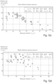
- FIG. 10 a shows a performance evaluation without drag force correction of closing the gap maneuvers for different parameter combinations in exemplary embodiments
- FIG. 10 b shows a performance evaluation without drag force correction of opening the gap maneuvers for different parameter combinations in exemplary embodiments
- FIG. 11 a illustrates a performance evaluation with drag force correction of closing the gap maneuvers for different parameter combinations in exemplary embodiments
- FIG. 11 b illustrates a performance evaluation with drag force correction of opening the gap maneuvers for different parameter combinations in exemplary embodiments
- FIG. 13 is an illustrative representation of the IVD during the transformation between platooning to HDPL and return from HDPL to platooning in an exemplary embodiment
- FIG. 14 shows an illustration of the influence of combinations of references on the final distance budget in an exemplary embodiment
- FIG. 15 a illustrates a surface model created by the graphical combination of the maneuver's duration and relative fuel consumption in an exemplary embodiment using a first lasso regression model
- FIG. 15 b illustrates a surface model created by the graphical combination of the maneuver's duration and relative fuel consumption in an exemplary embodiment using a second lasso regression model
- Vehicular communication is a field of research and development.
- transportation vehicles are expected to use Vehicle-to-Vehicle-communication (V2V) and Vehicle-to-Network (V2N) communication, e.g., to coordinate driving maneuvers and/or to receive tele-operated driving instructions.
- V2V Vehicle-to-Vehicle-communication
- V2N Vehicle-to-Network
- This communication is generally wireless, i.e., transportation vehicles may wirelessly communicate with other transportation vehicles in their vicinity and/or with backend services via cellular mobile communication systems.
- Automated or autonomous driving is also a field of research and development.
- One concept of dealing with high traffic loads is platooning, in which transportation vehicles are grouped and which may allow making more efficient use of the road capacity, lowering fuel consumption, respectively.
- the groups of transportation vehicles also referred to as convoys or platoons, may be used to operate the transportation vehicles in the platoon with a short distance or headway between the transportation vehicles, as the transportation vehicles within the platoon may react within a short time delay or simultaneously. This can be achieved by control mechanisms being active between the transportation vehicles of the platoon.
- an application supported by a communication system adapts its settings to the foreseen quality of service (QoS). It is especially important when the application in question is a safety-related time-critical application such as high-density platooning (HDPL), where inter-vehicle distances (IVDs) are below 15 m to benefit from reduced drag force and therefore from lower fuel consumption.
- HDPL high-density platooning
- IVDs inter-vehicle distances
- sensor systems may need to be supported by information transmitted by other transportation vehicles.
- the quality of the communication link is therefore critical as the performance of the application is strongly dependent on it. For example, transportation vehicles reduce their IVD to reduce their fuel consumption. They can achieve this distance reduction thanks to good communication conditions, about which they may have been made aware in advance (Predictive Quality of Service, PQoS). However, when the QoS degrades, the IVD has to be increased again.
- Document DE 10 2017 204 326 A1 provides further details on quality of service monitoring in a mobile communication system, in particular, for vehicular applications such as for platooning.
- Document DE 103 56 256 A1 describes a concept for quality monitoring of a radio interface.
- Document DE 10 2012 212 339 A1 discloses a grouping concept for transportation vehicles.
- Document DE 10 2016 226 050 A1 describes a concept for anticipatory pre-allocation or reservation of radio resource needed in the future to assure a certain quality of service.
- Document DE 10 2016 006 523 A1 discloses a concept for setting an inter-vehicle distance based on a certain traffic situation.
- Disclosed embodiments are based on the finding that an overall fuel efficiency of a platoon maneuver can be determined based on a fuel efficiency of the maneuver target state and based on a fuel efficiency of the transitional maneuvers to and from the maneuver target state. It is another finding that there is a trade-off for the transitional maneuvers between fuel efficiency for the transitional maneuvers and the overall fuel efficiency. For example, if the maneuver is to decrease the IVD to a certain value then the IVD can be decreased by deceleration maneuvers of the transportation vehicles in front until the IVD is reached. The IVD can increased by deceleration maneuvers of the transportation vehicles in the back of the platoon. The deceleration maneuver is more fuel efficient than an acceleration maneuver. However, the overall way progress of the platoon is decreased by the deceleration maneuver, which is also taken into account by exemplary embodiments.
- Disclosed embodiments provide a method for controlling a maneuver within a platoon of a plurality of transportation vehicles.
- the method comprises receiving information related to a maneuver for the platoon.
- the method further comprises determining information on a fuel efficiency of the maneuver based on fuel consumptions for maneuvering from an initial state to a maneuver target state, keeping the maneuver target state, and reverting from the maneuver target state to the initial state.
- the maneuver further comprises deciding on whether to perform the maneuver based on the information on the fuel efficiency.
- Disclosed embodiments provide efficient maneuver control in a platoon through overall fuel efficiency evaluation.
- the maneuver may be a high-density platooning maneuver for which an inter-vehicle distance of the maneuver target state is determined based on a communication latency between the transportation vehicles.
- Maneuvers may be controlled with respect to a given time frame, e.g., a predicted time frame, and a target state, e.g., a minimum IVD given by the communication latency. Fuel inefficient maneuvers may be avoided, transitional maneuvers may be improved or even optimized regarding an overall fuel efficiency of the maneuver.
- the method further comprises determining the inter-vehicle distance for the maneuver target state based on a predicted quality of service for inter-vehicle communication in the platoon.
- Disclosed embodiments may further adapt, improve, or optimize the target state based on the communication quality of the inter-vehicle communication.
- the information on the fuel efficiency may be further based on an overall duration for maneuvering from an initial state to a maneuver target state, keeping/maintaining the maneuver target state, and reverting from the maneuver target state to the initial state. Subdividing the maneuver in transitional maneuvers to and from the maneuver target state may enable further improvement of the fuel efficiency and evaluation, whether an overall fuel efficiency of the maneuver justifies the maneuver as such.
- the determining may comprise determining an effective time for the maneuver target state in some exemplary embodiments.
- the effective time may be based on the maneuvering from the initial state to the maneuver target state, the keeping of the maneuver target state, and the reverting from the maneuver target state to the initial state.
- Disclosed embodiments may use the effective time as an efficient model for evaluation and adapting the maneuver.
- the determining may further comprise determining the information on the fuel efficiency based on the effective time for the maneuver target state and a fuel saving rate during the maneuver target state.
- the effective time may then model the overall maneuver in the light of a predicted quality of service in exemplary embodiments.
- the determining of the effective time for the maneuver target state may comprise determining an actual time for maneuvering from the initial state to the target state and a compensation time for the maneuvering from the initial state to the target state.
- the determining of the effective time for the maneuver target state may further comprise determining an actual time for reverting from the target state to the initial state and a compensation time for reverting from the target state to the initial state. Compensation times in exemplary embodiments may be used to model positive and negative contributions of the transitional maneuvers to the overall maneuver in an efficient way.
- the method may further comprise evaluating different effective times for different reference points for the maneuvering from the initial state to the target state and for reverting from the target state to the initial state.
- a reference point may indicate a transportation vehicle in the platoon, which forms a maneuver reference for the other transportation vehicles in the platoon. For example, if the last transportation vehicle in the platoon forms the maneuver reference then all other transportation vehicles may decelerate to decrease the IVD in the platoon. Decelerating is more fuel efficient but overall travel distance of the platoon is lost. In case the leading transportation vehicle of the platoon forms the reference, all other transportation vehicles may accelerate to decrease the IVD in the platoon.
- Disclosed embodiments may take into account different transitional maneuvers using different reference transportation vehicles and thereby improve the overall fuel efficiency.
- the different effective times may result in different actual times and different compensation times, wherein at least one of the compensation times is negative.
- some maneuvers e.g., the acceleration maneuver with the last transportation vehicle as reference, may be considered with a negative compensation time because overall travel distance of the platoon may be gained.
- the transportation vehicles of the plurality of transportation vehicles may communicate with each other using a mobile communication system.
- the overall duration of the maneuver may be determined by a predicted quality of service in the mobile communication system. Such a prediction may be carried out at a transportation vehicle, an infrastructure component of the mobile communication system, or may involve both. For example, statistical information on a quality of service may be available on which a prediction can be based. For example, an overall duration for the maneuver may be determined based on the predicted quality of service. The overall duration may enable an overall fuel efficiency evaluation for the maneuver.
- Disclosed embodiments further provide a computer program having a program code for performing one or more of the above described methods, when the computer program is executed on a computer, processor, or programmable hardware component.
- a further exemplary embodiment is a computer readable storage medium storing instructions which, when executed by a computer, processor, or programmable hardware component, cause the computer to implement one of the methods described herein.
- Disclosed embodiments further provide an apparatus for controlling a maneuver within a platoon of a plurality of transportation vehicles.
- the apparatus comprises one or more interfaces for communicating with one or more transportation vehicles of the platoon of transportation vehicles.
- the apparatus further comprises a control module, which is configured to carry out one of the methods described herein.
- a transportation vehicle comprising an exemplary embodiment of the apparatus and a network component comprising an exemplary embodiment of the apparatus are further disclosed embodiments.
- the term “or” refers to a non-exclusive or, unless otherwise indicated (e.g., “or else” or “or in the alternative”).
- words used to describe a relationship between elements should be broadly construed to include a direct relationship or the presence of intervening elements unless otherwise indicated. For example, when an element is referred to as being “connected” or “coupled” to another element, the element may be directly connected or coupled to the other element or intervening elements may be present. In contrast, when an element is referred to as being “directly connected” or “directly coupled” to another element, there are no intervening elements present. Similarly, words such as “between”, “adjacent”, and the like should be interpreted similarly.
- FIG. 1 illustrates a block diagram of an exemplary embodiment of a method for controlling a maneuver within a platoon.
- the method 10 for controlling the maneuver within the platoon of the plurality of transportation vehicles comprises receiving 12 information related to a maneuver for the platoon.
- the method 10 further comprises determining 14 information on a fuel efficiency of the maneuver based on fuel consumptions for maneuvering from an initial state to a maneuver target state, keeping the maneuver target state, and reverting from the maneuver target state to the initial state.
- the method 10 further comprises deciding 16 on whether to perform the maneuver based on the information on the fuel efficiency.
- Examples of maneuvers of the platoon are an opening maneuver to add another transportation vehicle to the platoon, a closing maneuver for closing a gap of a leaving transportation vehicle, decreasing IVD to a target IVD for a certain time, etc.
- a platoon is a group or convoy of vehicles, e.g., transportation vehicles, cars, trucks, etc., that is coordinated.
- the transportation vehicles may communicate with each other directly or using infrastructure of a mobile communication system.
- the transportation vehicles of a platoon travel a common route section together and take advantage of travelling at a decreased IVD (fuel saving).
- maneuvers may be necessary or possible and whether such a maneuver may be beneficial or not may be determined in at least some exemplary embodiments.
- Disclosed embodiments determine a fuel efficiency, e.g., it may be evaluated whether an overall fuel consumption is higher or lower if a certain maneuver is carried out. Moreover, the maneuver or part of it, may be modified to make the maneuver fuel efficient. The fuel efficiency, i.e., whether more or less fuel is consumed by the platoon with the maneuver, may then form a basis to decide on whether the maneuver is performed or not.
- FIG. 2 illustrates a block diagram of an exemplary embodiment of an apparatus 20 for controlling a maneuver within a platoon, and an exemplary embodiment of a transportation vehicle 100 .
- the apparatus 20 comprises at least one (one or more) interfaces 22 for communicating with one or more transportation vehicles of the platoon of the plurality of transportation vehicles.
- the apparatus 20 comprises a control module 24 , which is coupled to the at least one interface 22 .
- the control module 24 may be configured to control the one or more interfaces 22 and to execute any of the methods described herein.
- FIG. 2 further illustrates an exemplary embodiment of a transportation vehicle/network component 100 comprising an exemplary embodiment of the apparatus 20 .
- the apparatus 20 , transportation vehicle 100 and the network component 100 may communicate through a mobile communication system 400 .
- the mobile communication system 400 may, for example, correspond to one of the Third Generation Partnership Project (3GPP)-standardized mobile communication networks, where the term mobile communication system is used synonymously to mobile communication network.
- 3GPP Third Generation Partnership Project
- the information related to the maneuver may hence be received through the mobile communication system 400 , e.g., from another transportation vehicle 102 as indicated in FIG. 2 .
- the request may be received from a central entity (network component), which controls the transportation vehicles 100 , 102 at least to a certain extent.
- the information related to the decision on whether to perform the maneuver may be provided to a transportation vehicle 102 or a network component.
- the mobile or wireless communication system 400 may correspond to a mobile communication system of the 5th Generation (5G, or New Radio) and may use mm-Wave technology.
- the mobile communication system may correspond to or comprise, for example, a Long-Term Evolution (LTE), an LTE-Advanced (LTE-A), High Speed Packet Access (HSPA), a Universal Mobile Telecommunication System (UMTS) or a UMTS Terrestrial Radio Access Network (UTRAN), an evolved-UTRAN (e-UTRAN), a Global System for Mobile communication (GSM) or Enhanced Data rates for GSM Evolution (EDGE) network, a GSM/EDGE Radio Access Network (GERAN), or mobile communication networks with different standards, for example, a Worldwide Inter-operability for Microwave Access (WIMAX) network IEEE 802.16 or Wireless Local Area Network (WLAN) IEEE 802.11, generally an Orthogonal Frequency Division Multiple Access (OFDMA) network, a Time Division Multiple Access (TDMA) network, a Code Division Multiple Access (CDMA) network, a
- Service provision may be carried out by a network component 100 , such as a base station transceiver, a relay station or a UE, e.g., coordinating service provision in a cluster or group of multiple UEs/vehicles.
- a base station transceiver can be operable or configured to communicate with one or more active mobile transceivers/vehicles 100 and a base station transceiver can be located in or adjacent to a coverage area of another base station transceiver, e.g., a macro cell base station transceiver or small cell base station transceiver.
- a mobile communication system 400 comprising two or more mobile transceivers/vehicles 100 and one or more base station transceivers, wherein the base station transceivers may establish macro cells or small cells, as e.g., pico-, metro-, or femto cells.
- a mobile transceiver or UE may correspond to a smartphone, a cell phone, a laptop, a notebook, a personal computer, a Personal Digital Assistant (PDA), a Universal Serial Bus (USB)-stick, a car, a transportation vehicle etc.
- PDA Personal Digital Assistant
- USB Universal Serial Bus
- a mobile transceiver may also be referred to as User Equipment (UE) or mobile in line with the 3GPP terminology.
- UE User Equipment
- a transportation vehicle may correspond to any conceivable method or mechanism for transportation, e.g., a car, a bike, a motorbike, a van, a truck, a bus, a ship, a boat, a plane, a train, a tram, etc.
- a base station transceiver can be located in the fixed or stationary part of the network or system.
- a base station transceiver may be or correspond to a remote radio head, a transmission point, an access point, a macro cell, a small cell, a micro cell, a femto cell, a metro cell etc.
- a base station transceiver can be a wireless interface of a wired network, which enables transmission of radio signals to a UE or mobile transceiver.
- Such a radio signal may comply with radio signals as, for example, standardized by 3GPP or, generally, in line with one or more of the above listed systems.
- a base station transceiver may correspond to a NodeB, an eNodeB, a gNodeB, a Base Transceiver Station (BTS), an access point, a remote radio head, a relay station, a transmission point, etc., which may be further subdivided in a remote unit and a central unit.
- BTS Base Transceiver Station
- a mobile transceiver or transportation vehicle 100 , 102 can be associated with a base station transceiver or cell.
- the term cell refers to a coverage area of radio services provided by a base station transceiver, e.g., a NodeB (NB), an eNodeB (eNB), a gNodeB, a remote radio head, a transmission point, etc.
- NB NodeB
- eNB eNodeB
- gNodeB gNodeB
- a base station transceiver may operate one or more cells on one or more frequency layers, in some exemplary embodiments a cell may correspond to a sector. For example, sectors can be achieved using sector antennas, which provide a characteristic for covering an angular section around a remote unit or base station transceiver.
- a base station transceiver may, for example, operate three or six cells covering sectors of 120° (in case of three cells), 60° (in case of six cells) respectively.
- a base station transceiver may operate multiple sectorized antennas.
- a cell may represent an according base station transceiver generating the cell or, likewise, a base station transceiver may represent a cell the base station transceiver generates.
- the apparatus 20 may be comprised in a transportation vehicle, base station, a NodeB, a UE, a relay station, or any service coordinating network entity in exemplary embodiments.
- the term network component may comprise multiple sub-components, such as a base station, a server, etc.
- a further exemplary embodiment is a transportation vehicle 100 comprising the apparatus 20 and/or a network component comprising the apparatus 20 .
- the one or more interfaces 22 may correspond to any method or mechanism for obtaining, receiving, transmitting or providing analog or digital signals or information, e.g., any connector, contact, pin, register, input port, output port, conductor, lane, etc. which allows providing or obtaining a signal or information.
- An interface may be wireless or wireline and it may be configured to communicate, i.e., transmit or receive signals, information with further internal or external components.
- the one or more interfaces 22 may comprise further components to enable according communication in the mobile communication system 400 , such components may include transceiver (transmitter and/or receiver) components, such as one or more Low-Noise Amplifiers (LNAs), one or more Power-Amplifiers (PAs), one or more duplexers, one or more diplexers, one or more filters or filter circuitry, one or more converters, one or more mixers, accordingly adapted radio frequency components, etc.
- the one or more interfaces 22 may be coupled to one or more antennas, which may correspond to any transmit and/or receive antennas, such as horn antennas, dipole antennas, patch antennas, sector antennas etc.
- the antennas may be arranged in a defined geometrical setting, such as a uniform array, a linear array, a circular array, a triangular array, a uniform field antenna, a field array, combinations thereof, etc.
- the one or more interfaces 22 may serve the purpose of transmitting or receiving or both, transmitting and receiving, information, such as information related to capabilities, application requirements, trigger indications, requests, message interface configurations, feedback, information related to control commands, QoS requirements, QoS maps, etc.
- control module 24 may be implemented using one or more processing units, one or more processing devices, any method or mechanism for processing, such as a processor, a computer or a programmable hardware component being operable with accordingly adapted software.
- the described functions of the control module 24 may as well be implemented in software, which is then executed on one or more programmable hardware components.
- Such hardware components may comprise a general-purpose processor, a Digital Signal Processor (DSP), a micro-controller, etc.
- DSP Digital Signal Processor
- FIG. 2 also shows an exemplary embodiment of a system 400 comprising disclosed embodiments of UE/vehicle/network component 100 , and another transportation vehicle 102 , it may as well comprise one or more network components/base stations comprising further exemplary embodiments of the apparatus 20 .
- communication i.e., transmission, reception or both, may take place among mobile transceivers/vehicles 100 , 102 directly and/or between mobile transceivers/vehicles 100 , 102 and a network component (infrastructure or mobile transceiver, e.g., a base station, a network server, a backend server, etc.).
- a network component infrastructure or mobile transceiver, e.g., a base station, a network server, a backend server, etc.
- Such communication may make use of a mobile communication system 400 .
- Such communication may be carried out directly, e.g., by Device-to-Device (D2D) communication, which may also comprise Vehicle-to-Vehicle (V2V) or car-to-car communication in case of transportation vehicles 100 , 102 .
- D2D Device-to-Device
- V2V Vehicle-to-Vehicle
- car-to-car communication in case of transportation vehicles 100 , 102 .
- Such communication may be carried out using the specifications of a mobile communication system 400 .
- the one or more interfaces 22 can be configured to wirelessly communicate in the mobile communication system 400 .
- radio resources are used, e.g., frequency, time, code, and/or spatial resources, which may be used for wireless communication with a base station transceiver as well as for direct communication.
- the assignment of the radio resources may be controlled by a base station transceiver, i.e., the determination which resources are used for D2D and which are not.
- radio resources of the respective components may correspond to any radio resources conceivable on radio carriers and they may use the same or different granularities on the respective carriers.
- the radio resources may correspond to a Resource Block (RB as in LTE/LTE-A/LTE-unlicensed (LTE-U)), one or more carriers, sub-carriers, one or more radio frames, radio sub-frames, radio slots, one or more code sequences potentially with a respective spreading factor, one or more spatial resources, such as spatial sub-channels, spatial precoding vectors, any combination thereof, etc.
- RB Resource Block
- LTE-U LTE/LTE-A/LTE-unlicensed
- LTE-U LTE/LTE-A/LTE-unlicensed
- spatial resources such as spatial sub-channels, spatial precoding vectors, any combination thereof, etc.
- C-V2X direct Cellular Vehicle-to-Anything
- V2X includes at least V2V, V2-Infrastructure (V2I), etc.
- transmission according to 3GPP Release 14 onward can be managed by infrastructure (so-called mode 3 ) or run in
- the method 10 may be carried out at the apparatus 20 in the transportation vehicle 100 .
- the transportation vehicle 100 may receive information related to a maneuver for the platoon, e.g., from another transportation vehicle 102 , from a controlling network component, from a platoon determining control entity, etc.
- the transportation vehicle or network component 100 may then determine 14 information on the fuel efficiency of the maneuver based on fuel consumptions for maneuvering from the initial state to the maneuver target state, keeping the maneuver target state, and reverting from the maneuver target state to the initial state.
- the transportation vehicle or network component 100 may then decide 16 on whether to perform the maneuver based on the information on the fuel efficiency.
- AQoSA provides information on the future quality of the link. This information may come with a prediction horizon, that is a delta time (a duration from now on), which ends in the future, for which the predicted value is applicable. Knowing the predicted value over time, the cost of the quality of service, the application may compute how long it needs to use the QoS to compensate the cost of the maneuver and the cost of the service in some exemplary embodiments.
- a predictive quality of service (PQoS) time series is a series of values representing a future quality of the link.
- a maneuver may comprise a closing maneuver (going from the initial inter transportation vehicle distance (IVD) of the platoon d i , for instance, 30 m, to a smaller, final IVD d f ), maintain this final IVD d f for a while, and then perform an opening manoeuver (going back to d i ).
- This set of maneuvers is limited by the length of the favorable QoS period (the duration of future QoS during which the platoon can drive at low IVD) T F .
- the maneuver is a high-density platooning (HDPL) maneuver for which an inter-vehicle distance of the maneuver target state is determined based on a communication latency between the transportation vehicles.
- the inter-vehicle distance for the maneuver target state is determined based on a predicted quality of service for inter-vehicle communication in the platoon.
- the predicted latency for a message exchange determines a minimum IVD, e.g., based on an emergency braking maneuver.
- the IVD needs to provide enough time buffer for communication of an emergency brake message.
- the transportation vehicles of the plurality of transportation vehicles communicate with each other using a mobile communication system, e.g., a mobile communication system enabling V2V or C2C.
- the maneuver is determined by a predicted quality of service (PQoS) in the mobile communication system.
- PQoS predicted quality of service
- a time horizon of the PQoS determines an overall duration of the maneuver.
- an overall duration for the maneuver is determined based on the PQoS.
- a fuel saving for HDPL may be improved or (theoretically maximized).
- the IVD may be reduced as fast as possible to reach the low air drag area and benefit from HDPL the longest.
- the information on the fuel efficiency may be further based on an overall duration for maneuvering from an initial state to a maneuver target state, keeping the maneuver target state, and reverting from the maneuver target state to the initial state.
- the determining 14 may comprise determining an effective time for the maneuver target state. The effective time may be based on the maneuvering from the initial state to the maneuver target state, the keeping of the maneuver target state, and the reverting from the maneuver target state to the initial state.
- Disclosed embodiments may model a relative fuel saving (FS) as a function of the effective HDPL time (TH) and the fuel saving rate at the target distance (c d f ).
- F S c d f T H .
- the determining 14 comprises determining the information on the fuel efficiency based on the effective time (TH) for the maneuver target state and a fuel saving rate c d f during the maneuver target state.
- This notion of effective HDPL time is the HDPL time accounting for the maneuver investment in fuel and distance. For this, compensation times TC for the maneuver fuel investment can be introduced.
- T C C c d f .
- the determining 14 of the effective time for the maneuver target state may comprise determining an actual time for maneuvering from the initial state to the target state and a compensation time for the maneuvering from the initial state to the target state.
- the determining 14 of the effective time for the maneuver target state may comprise determining an actual time for reverting from the target state to the initial state and a compensation time for reverting from target state to the initial state.
- At least some exemplary embodiments may evaluate different effective times for different reference points for the maneuvering from the initial state to the target state and for reverting from the target state to the initial state.
- a reference point indicates a transportation vehicle in the platoon, which forms a maneuver reference for the other transportation vehicles in the platoon, as it is further detailed in FIG. 3 .
- the different effective times result in different actual times and different compensation times, wherein at least one of the compensation times is negative. This time can be negative if the maneuver already saves fuel (e.g., all trucks decelerate to reduce the IVD).
- FIG. 3 illustrates the concept of distance investment in an exemplary embodiment.
- FIG. 3 shows a platoon of three transportation vehicles for which at a first time instant, which is shown on the very left, the IVD is di.
- the first row of the matrix representation in FIG. 3 depicts the progress without conducting a maneuver.
- the IVD of the three transportation vehicles remains constant.
- development over time for a HDPL maneuver is shown.
- the IVD is reduced to df in a closing maneuver and the result is depicted in the middle.
- the IVD is then increased back to di, which is shown on the right.
- Different reference points rc, ro are considered for the closing and opening maneuvers.
- Value 0 means that the leading transportation vehicle is the reference point
- value 0.5 indicates that the center transportation vehicle is the reference point
- value 1 indicates that the last transportation vehicle is the references point.
- the different rc, ro combinations are shown on the very left. In the second row the leading transportation vehicle is the reference for both transitional maneuvers. As can be seen on the very right, after the opening maneuver the platoon made the same progress as in the first row without the maneuver. The position of the first transportation vehicle in this case is marked with a baseline. As can be seen through the combinations some maneuver configurations gain way progress and some loose way progress.
- the baseline hence represents the case in which no maneuver is performed.
- the initial state is shown, and in the middle the HDPL (maneuver target) state is shown.
- the final state is shown.
- some maneuvers introduce a distance deficit (first truck/transportation vehicle behind (left of) the baseline) and some a distance gain (first truck/transportation vehicle in front of (right of) the base line.
- the platoon needs to drive a bit longer to compensate the baseline, with which the relative fuel saving can be computed in disclosed embodiments.
- a gain it means that the platoon needs to drive less afterwards, meaning that this can be translated into a fuel gain compared to the baseline. More details on how rc, ro can be obtained can be found in application EP 19 170 887.4.
- T C D This can be resumed as T C D , a distance compensation time accounting for the distance deficit or gain of the maneuver.
- T C c is the compensation time of the fuel investment of the closing maneuver
- T C o is the compensation time of the opening maneuver, respectively.
- these times are obtained as laid out in application EP 19 170 887.4. These times are functions of the final/target IVD df, the maneuver reference, the maximal velocity deviation and other control parameters (acceleration deviation, control gain etc.).
- At least some exemplary embodiments can maximize or improve the fuel saving of HDPL by solving the following
- rc is the reference of the closing maneuver
- ro is the reference of the opening maneuver
- ⁇ vc is the maximum speed deviation of the closing maneuver
- ⁇ vo is the maximum speed deviation of the opening maneuver
- df is the final IVD.
- Disclosed embodiments may maximize or improve the fuel saving by taking into account compensation times for the fuel investment of the closing and opening maneuvers, as well as the distance deficit/gain.
- the HDPL parameters can be chosen accordingly in exemplary embodiments.
- the signaling may be implemented in a centralized or in a distributed way.
- a transportation vehicle within the platoon may carry out the method 10 and inform/coordinate the platoon members.
- the method 10 may be carried out at a control center in an infrastructure network component and the results may be communicated to the members of the platoon, or a coordinating member of the platoon.
- a fully distributed implementation is conceivable in which the method 10 is carried out at least partly at each of the platoon members. Then an additional coordination or reconcilement communication may be carried out among the members of the platoon to assure corporate maneuvering.
- the respective methods may be implemented as computer programs or codes, which can be executed on a respective hardware.
- a computer program having a program code for performing at least one of the above methods, when the computer program is executed on a computer, a processor, or a programmable hardware component.
- a further disclosed embodiment is a computer readable storage medium storing instructions which, when executed by a computer, processor, or programmable hardware component, cause the computer to implement one of the methods described herein.
- a promising application in the scope of cooperative driving is high-density platooning.
- One of the main goals of this application is to reduce the fuel consumption by benefiting from reduced air drag from driving inter-vehicle distances below ten meters.
- the application strongly relies on vehicle-to-vehicle communications.
- a recent concept is agile quality of service adaptation, in which the application is receiving a prediction of the future quality of service, from the network, for instance, and adapts its settings to cope with its variation.
- An important parameter in this concept is the prediction horizon, that is the length of the provided predicted quality of service time series. This parameter drives the duration of the reduced air drag benefit as a function of the maneuvering time series. Indeed, a short prediction horizon can be used, but requires fast reaction of the application. This is often linked to higher fuel consumption during the adaptation maneuver, thus impairing the original goal of high-density platooning.
- the influence of the prediction horizon on the fuel saving is a function of different maneuver parameters.
- the relationship between the maneuvering duration and the fuel consumption for increasing and decreasing the inter-vehicle distance can be considered in exemplary embodiments.
- the maneuver fuel investment can be linked with a compensation time, during which the platoon will counterbalance the fuel consumption by benefiting from the reduced air drag.
- Some exemplary embodiments may use an optimization method for maximizing the fuel efficiency depending on some predictive quality of service (PQoS) parameters.
- PQoS predictive quality of service
- the order of magnitude of the prediction horizon required by a five-truck platoon may be minimum one hundred seconds.
- HDPL high-density platooning
- truck platooning aiming for energy efficiency has gained a lot of attention in the field of cooperative transportation vehicle automation research, cf. S. Tsugawa, S. Jeschke, and S. E. Shladover, “A review of truck platooning projects for energy savings,” IEEE Trans. on Intell. Veh., vol. 1, no. 1, pp. 68-77, March 2016, and S. van de Hoef, K. H. Johansson, and D. V. Dimarogonas, “Fuel-efficient en route formation of truck platoons,” IEEE Trans. on Intell. Transp. Syst., vol. 19, no. 1, pp. 102-112, January 2018.
- V2V vehicle-to-vehicle
- V2X vehicle-to-everything
- the application and the communications system periodically exchange QoS requirements and PQoS, respectively.
- the adaptation of the QoS requirements operate together with the adaptation of its functional settings.
- AQoSA allows the platoon to plan its maneuver. This includes reducing its IVD, maintaining the small IVD and increasing the IVD.
- This planning strongly depends on the QoS provided by the communication systems.
- the values in the PQoS time series drive the minimum IVD, which affects the fuel saving. Its length will also affect the fuel saving, as the longer the favorable time, the larger the fuel saving. To achieve fuel saving, the duration of this favorable QoS should be longer than a threshold.
- the requirements on the QoS may differ, especially in terms of prediction horizon.
- This prediction horizon is defined as the total length of the PQoS timeseries. Therefore, in a HDPL maneuver, it may encompass the IVD reduction (closing) maneuver, the reduced air drag period as well as the IVD increase (opening) maneuver and some compensation times.
- an exemplary embodiment may provide a concept for group control, the relative reference for the maneuver, along with other relevant control parameters.
- the reference concept may extend the graph-based Laplacian control algorithm presented in
- the simulated truck platoon may obtain the PQoS information from a prediction algorithm running on an arbitrary node.
- the prediction algorithm that provides the PQoS could run on a base station, or be running on the nodes, such as in
- the fuel consumption model of SUMO may be adapted to reflect the air drag reduction.
- a Pareto frontierlike relationship between the two objectives may be derived.
- the fuel consumption investment can be translated into a compensation time.
- the resulting sets of maneuvering time/compensation time for the two maneuvers allow performing fuel saving optimization or improvement depending on the available PQoS.
- Disclosed embodiments may extend the distributed graph-based feedback convoy controller for closing and opening maneuvers; consider the relationship between fuel consumption and maneuvering time depending on the control strategy and improve or optimize the fuel saving depending on the PQoS.
- Disclosed embodiments may provide a fuel-efficient approach for HDPL using PQoS. This may require deriving the relationship between maneuvering time and fuel consumption through the simulation of a HDPL scenario. Indeed, to compute the time required to have actually achieve fuel saving, the maneuvers have to be accounted for. The closing and opening maneuvering times have to be deduced from the future favorable QoS time series. Moreover, if the maneuvers consume fuel, exemplary embodiments may also account for its compensation by deducting compensation times. The sum of the maneuvering times and the compensation times therefore drives the PQoS prediction horizon. Another important feature for this approach is the development of a control strategy for the two maneuvers involved.
- a standardized platooning scenario on a closed circuit is considered. This allows running the same scenario, independent on the actual maneuvering time, assuming that the platoon will achieve the formation changes in the imparted time.
- a scenario is divided in five phases: (i) platooning; (ii) IVD reduction; (iii) HDPL; (iv) IVD augmentation and (v) platooning.
- the platoon targets an IVD related to a normal platooning use-case, for instance, 30 m.
- the platoon receives an information on a future favorable QoS and triggers the reduction of the IVD (ii) to reduce the drag force experienced by the follower transportation vehicles, aiming to reduce the overall fuel consumption.
- the platoon targets an IVD of 5 m.
- the platoon is then made aware of a degradation of the QoS and triggers the increase of the IVD (iv).
- the maneuver is achieved, that is when the IVD is back to its original value, the platoon continues to drive (v).
- a platoon is composed of five trucks, driving on the test circuit, as illustrated in FIG. 4 .
- FIG. 4 illustrates scenario snapshots: (a) simulation model of a test track facility, and (b) zoom in on the five-truck platoon in this disclosed embodiment.
- the scenario is divided into three periods of 100 s: (i); (ii-iii); and (iv-v).
- the actual durations of the phases (ii) to (iv) depend on the maneuvering strategies implemented and are results of these experiments.
- the phases (i) and (iii) provide stabilization periods.
- the data gathered in this time-triggered implementation allows developing strategies to process actual PQoS time series. Each experiment indeed yields two maneuvering times and two maneuvering fuel consumptions.
- a distributed control algorithm is based on the Laplacian control principle, cf. M. Mesbahi and M. Egerstedt, Graph theoretic methods in multiagent networks. Princeton University Press, 2010, vol. 33.
- VANET vehicular ad hoc network
- Disclosed embodiments may enhance the offset and bias mechanisms.
- the offset and bias are calculated with respect to the reference transportation vehicle, which is the front transportation vehicle. This definition is appropriate for the creation and the maintenance of the convoy, even more when it is composed of heterogeneous transportation vehicles.
- FIG. 5 illustrates simple examples of combination of objectives and maneuvers.
- FIG. 5 illustrates reference placement in exemplary embodiments for (a) fuel consumption optimization with reference in the back, (b) maneuver duration optimization with reference at the center, compared to (c) classical reference in the front during an IVD closing maneuver.
- FIG. 5 comprises the fuel consumption time series, the speed time series and an illustration of the reference influence on the maneuver.
- plain curves represent the instantaneous consumption without air drag consideration.
- the overall consumption of the platoon over the 50 s experiment is also given in the top right corner.
- Instantaneous fuel consumption considering the air drag reduction induced by preceding transportation vehicles are represented by low opacity curves.
- the maneuvering time TM is indicated.
- the direction of driving is from left to right and the horizontal arrows represent the direction of the acceleration.
- variable parameters used to evaluate the relationship between fuel consumption and maneuvering time in an exemplary embodiment are described.
- the computation methods for these two objectives in an exemplary embodiment are then described before presenting the fuel consumption model evaluation that is used to highlight the benefit of HDPL.
- a control strategy has three independent features: (i) the platooning controller, (ii) the local controller and (iii) the command input verification.
- the platooning controller which enables the group behavior, is described subsequently.
- the local controller translates the speed received from the platooning controller into an acceleration command.
- the command input verification ensures that the speed and acceleration commands do not violate the dynamics constraints.
- FIG. 6 illustrates platoon input parameters and time objective in an exemplary embodiment.
- the influence of the control gain kl is depicted for trucks 0 and 4.
- the speeds and accelerations are bounded to vg ⁇ v and ⁇ amax respectively.
- the maneuvering time though defined by a deviation threshold, can be also observed in FIG. 6 .
- FIG. 6 illustrates the parameters described in the following with the speed profile of an IVD change.
- Different platooning strategies may be applied in disclosed embodiments that allow to achieve trade-offs between the two objectives.
- Three example strategies are front, center and back references, further referred as r ⁇ 0,0.5,1 ⁇ , respectively, in a platoon with an odd number of transportation vehicles.
- This variable is used to find the reference transportation vehicle index as r ⁇ (Nv ⁇ 1), with Nv the number of transportation vehicles in the platoon (the numbering starts with 0).
- the reference point is not restricted to a transportation vehicle and can be placed anywhere within the platoon.
- the control gain is a parameter of the local controller and dictates how tolerant the algorithm is with differences between the current formation and the target formation. A larger control gain kl, within a reasonable value interval, will achieve faster maneuver, at the cost of a potentially larger fuel consumption.
- Some exemplary embodiments may aim at two objectives, minimizing the maneuver time and minimizing the fuel consumption.
- the former is of interest for the communications system, as it drives the prediction horizon for PQoS.
- the latter is an inherent objective of the platooning system, reducing fuel consumption.
- Tm The maneuver time, Tm, can be defined as the duration between the trigger of the IVD change (Tt) and the time at which the target is reached. This happens when: max( ⁇ i ) ⁇ , where
- ⁇ i ⁇ " ⁇ [LeftBracketingBar]" s - b ⁇ " ⁇ [RightBracketingBar]” _ ⁇ ⁇ ⁇ i (see Eq. (1)) for the local graph of node i and ⁇ is a tolerance value, 1 m in the presented results.
- ⁇ i is related to the mean deviation between the IVD and the target IVD for each transportation vehicle.
- the derivation of the duration is illustrated in FIG. 7 .
- FIG. 7 illustrates a graph deviation as a function of time and derivation of T m , the maneuver duration in an exemplary embodiment. The value of ⁇ has been exaggerated for representation purposes.
- the surges that can be observed, for instance, for trucks 0 and 3 around 12 s correspond to changes in the nodes number in the local graphs, typically increasing in an IVD reduction maneuver.
- the maneuver duration is also represented in FIG. 6 , as the stabilization of the truck speeds also corresponds to the achievement of the target formation.
- the maneuver cost, C is the total fuel consumption of the platoon during the maneuver, expressed as a difference with the consumption of the same platoon not performing the maneuver. Each parameter's set is therefore applied a second time to obtain the baseline.
- the relative fuel consumption is therefore computed as:
- C i , k ⁇ 0 T m c i , k ⁇ dt k ⁇ ⁇ m , b ⁇ ( 3 )
- C C m - C b , ( 5 )
- C is the relative maneuver cost
- C k the total fuel consumption during the maneuver, with C m and C b corresponding to the maneuver and the baseline respectively.
- Ci,k and ci,k are the total and instantaneous fuel consumption for truck i.
- some disclosed embodiments rely on the fuel consumption model of the traffic simulator SUMO, HBEFA3/HDV_TT, described in S. Hausberger and D. Krajzewicz, “COLOMBO Deliverable 4.2: Extended Simulation Tool PHEM coupled to SUMO with User Guide,” February 2014.
- the expected gain of truck platooning is a decreased overall fuel consumption. It is enabled by the reduced air drag experienced by each platoon member.
- Fuel consumption models integrated in microscopic vehicular simulators generally take into account individual transportation vehicle parameters such as speed and acceleration. In a HDPL system, the air drag experienced by a truck is also strongly dependent on the other platoon members. As a result, an air drag correction strategy can be developed, taking as inputs for each truck:
- FIG. 8 illustrates an air drag ratio as a function of IVD for five trucks in a platoon in an exemplary embodiment. It is assumed that the fourth and fifth trucks experience the same ratio as the third one. An air drag ratio of 1 corresponds to the truck driving alone, that is experiencing no benefit from other platooning trucks.
- FIG. 9 shows a relative fuel saving as a function of the final IVD for various initial IVDs in disclosed embodiments. An approximate correspondence in percentage is given as secondary axis.
- performing HDPL at 5 m in comparison with platooning at 30 m is 2.2 mL/s with five trucks. These values will be used to calculate a compensation time for the maneuver fuel investment in the next sections. This subsequently allows to transform fuel investments to compensation times and vice versa. This is particularly useful when it comes to optimizing for both objectives: minimizing the fuel consumption and the maneuvering times.
- Simulation parameters will be described first. Two sets of experiments will be performed. The first one allows to closely study the relationship between maneuver duration and fuel consumption for one combination of initial and final IVDs. The impact of the fuel consumption on this relationship is also studied. Using the insights gathered with these results, the relationship for multiple combinations of initial and final IVDs can be generalized.
- the HDPL scenario can be run with a coupled traffic and network simulator, with SUMO and ns-3.
- the control strategies implemented are described in the previous section directly in ns-3. Leveraging the tracing capabilities of ns-3, instantaneous IVD, speed, fuel consumption and graph deviation time series can be gathered for combinations of the control parameters.
- a first phase the impact of the control parameters can be studied for a specific combination of initial and final IVDs.
- the insights gathered can be used in the first phase to extend the results to multiple combinations of initial and final IVDs.
- Some exemplary embodiments derive strategy choices for the closing and opening maneuvers depending on the PQoS time series. This choice is driven by two concurrent objectives, the minimization (reduction) of the fuel consumption and of the maneuvering time. Indeed, for the overall problem, the longer the maneuver, the higher the risk of having to perform an earlier and faster opening maneuver. The risk is higher because of the low confidence in the provided PQoS.
- FIG. 10 shows the relationship between the relative fuel consumption and the maneuvering time for the two maneuvers when no drag force correction is applied.
- FIG. 10 shows a performance evaluation without drag force correction of (a) closing the gap and (b) opening the gap maneuvers for different parameter combinations in disclosed embodiments.
- the different markers depict the different versions of the CACC algorithm: Bullets stand for the classical front reference; squares for the center reference, optimized for time; and diamonds for the back reference, r ⁇ 0, 0.5, 1 ⁇ , respectively.
- the sizes of the markers are proportional to the maximal speed deviation ⁇ v ⁇ 1, 2, 3 ⁇ m/s.
- the bold curve indicates the approximate Pareto front, that is the line for which the improvement of one objective is obtained with the deterioration of the other.
- the middle reference always outperforms the two other references, at the cost of a larger fuel consumption.
- “catching up” (front reference) to close the gap will consume more fuel than slowing down, and vice-versa.
- An interesting result for the strategy choice is the approximate symmetry between the front and back reference across the two maneuvers (highlighted with the ellipses and Roman numbers in FIG. 10 ). For instance, by switching between the two references, it is possible to perform the two maneuvers in 80 s while investing less than 300 mL.
- FIG. 11 illustrates a performance evaluation with drag force correction of (a) closing the gap and (b) opening the gap maneuvers for different parameter combinations in exemplary embodiments.
- the marker shape and size schemes are identical to the previous figure.
- the approximate Pareto frontier of the uncorrected results has been added in dashed for comparison purposes.
- the trends highlighted in the description and analysis of the previous set of results generally hold once the aforementioned correction is applied.
- the opening maneuver shows a smaller dependency of the corrections to the maneuver time. These are stable between 50 and 60 mL of the middle and front references.
- the back-reference maneuvers benefit the most from HDPL, as the front trucks keep the small IVD longer.
- FIG. 11 also indicates the HDPL time necessary to compensate the fuel investment, using the aforementioned value of 2.92 mL/s. Fast maneuvers tend to yield very high compensation time, motivating to find an appropriate trade-off considering the available PQoS timeseries.
- a general trend in the dependency between the two metrics can be observed: The metric pairs are placed along a front for each pair ⁇ di, df ⁇ . This trend is similar to the approximate Pareto-front described in the previous results set. It can also be observed that the parameter ⁇ v drives the values along the front, i.e., increasing Av reduces the maneuvering time whilst increasing the relative fuel consumption.
- exemplary embodiments may provide the best or an improved strategy for HDPL, accounting for the fuel consumption and the duration of the closing and opening maneuvers.
- the first operation is to translate the PQoS time series into a minimum allowed IVD considering the safety of the platoon.
- An example of such translation is provided in
- the result of this translation operation can be represented as a pair of values, a favorable time TF and a minimum IVD allowance dm.
- TF denotes the duration of the allowed dm.
- the aim is then to choose an final IVD df and the corresponding r and ⁇ v for the closing and opening maneuvers.
- the platoon should only change its IVD to df with di>df ⁇ IVDmin if it is possible to execute the opening and closing maneuver and save fuel within a duration TF.
- di denotes the initial IVD and is the IVD of the platoon before starting the maneuver. It is assumed that after the HDPL maneuver, the platoon targets the same distance.
- Disclosed embodiments may Aim at maximizing this benefit whilst respecting the constraints imposed by the QoS time series, viz. the dm and TF, the minimum drivable IVD and the time during which it is possible to drive it, respectively.
- the optimization problem can then be formulated as
- FS is the effective fuel saving after deducing all maneuver investments.
- FS can be derived as a function of different maneuvering parameters.
- a continuous model for the relationship between maneuver fuel investments and times can be proposed.
- An evolutionary algorithm can be applied to solve the problem and present its results.
- the effective fuel saving time TH is equal to the time during which the HDPL benefits from the small IVD. It takes all maneuver investment into account, e.g., cost of closing and opening the gap. These maneuver investments are taken into consideration as compensation times for the opening and closing maneuvers.
- the compensation time corresponds to the time during which the HDPL has to maintain its target IVD to save enough fuel to compensate a maneuver fuel investment.
- the compensation time for closing and opening maneuvers can be denoted as T C c and T C o , respectively. Both are obtained by dividing the maneuver relative fuel consumptions C by the fuel saving rate c d f , which depends on the chosen df.
- T H T F ⁇ T M c ⁇ T C c ⁇ T M o ⁇ T C o ⁇ T C d , (16)
- T M c and T M o are the durations of the closing and opening maneuvers, respectively.
- the results presented in the previous section support that for some combinations of parameters, the compensation time can be null or negative. It is indeed possible to consume no fuel or even save fuel during maneuvers, in which case TH includes part of the maneuvering time.
- the following table summarizes the different durations involved and FIG. 13 illustrates their dependence to IVDs.
- FIG. 13 is an illustrative representation of the IVD during the transformation between platooning to HDPL and return from HDPL to platooning in an exemplary embodiment. It represents the IVD during closing and opening maneuvers, each maneuver compensation time and fuel saving duration.
- a platoon not performing any maneuver can be used as baseline.
- the overall traveled distance remains identical as the baseline.
- this traveled distance is different (see FIGS. 3 and 14 ) and needs to be taken into consideration. Indeed, the platoon will consume fuel to travel a positive distance difference, or has saved fuel when it is negative.
- FIG. 14 shows an illustration of the influence of combinations of references on the final distance budget in an exemplary embodiment.
- This example shows a three-truck platoon performing a closing maneuver and a closing maneuver with different references. Depending on the combination, the platoon would have “won” or “lost” distance compared to the baseline, just like detailed above with respect to FIG. 3 .
- the traveled distance compensation time T C D is introduced. It corresponds to the time during which the HDPL has to maintain its target IVD to compensate the fuel related to the distance difference. T C D has the opposite sign of the distance difference. A negative T C D is then equivalent to extend TH. T C D is computed as
- r c ,r o ⁇ 0,0.5,1 ⁇ .
- a least absolute shrinkage and selection operator (Lasso) model cf. R. Tibshirani, “Regression shrinkage and selection via the lasso,” Journal of the Royal Statistical Society (Series B), vol. 58, pp. 267-288,1996, are fit to the data.
- Lasso is a regression method that executes a variable selection and regularization operation to improve the prediction accuracy.
- Lasso constraints the sum of the coefficient absolute values under a threshold.
- the coefficients of the parameters with small or no influence on the predicted variable are set to zero or close to it. This constraint implements both the regularization and the variable selection.
- the Lasso parameters ⁇ L are computed using the following minimization:
- ⁇ ⁇ L arg ⁇ min ⁇ ⁇ R p ⁇ ⁇ y - X ⁇ ⁇ ⁇ 2 2 + ⁇ ⁇ ⁇ ⁇ ⁇ 1 , ( 19 )
- ⁇ is the vector of coefficients
- X the matrix of observations
- ⁇ is a tuning parameter, a positive or null constant that represents the shrinkage penalty.
- Lasso is a univariate analysis method: The two observed variables, duration and relative fuel consumption, have therefore to be modeled separately.
- the platoon When executing a closing maneuver, the platoon saves more fuel at the end of the maneuver than at the beginning. This is reinforced by the shape of the IVD time series (which can be deduced from the graph deviation time series in FIG. 7 ). Indeed, a longer part of the maneuver occurs at small IVDs due to the behavior of the proportional part of the controller.
- the opening maneuver is the opposite, as it starts at the most profitable IVDs to then move quickly away from it. In the same conditions (initial and final IVDs, and reference), both maneuvers take approximately the same duration, but opening saves more than closing, as it is possible to notice when comparing FIGS. 12 ( b ) and 12 ( d ) .
- Each maneuver reference induces a different behavior in terms of transportation vehicles movement. This impacts the aerodynamic conditions variation and therefore the fuel consumptions on the one hand, and the maneuver duration on the other hand. Front and back references usually yield similar durations and different consumptions (with a symmetry, as highlighted in FIG. 10 ). Middle reference normally yields the shortest maneuvers, as FIG. 11 shows.
- the inputs of these regressions are the initial and final IVDs, di and df respectively, and the speed boundaries ⁇ v. Observing the shapes of the different points in the results presented in the previous section, the target variables show a polynomial dependency on speed boundaries.
- the polynomial combination of our features can be taken without risking over-fitting.
- FIG. 15 presents the exemplary outcomes for a front reference closing maneuver and a middle reference opening maneuver.
- FIG. 15 illustrates a surface model created by the graphical combination of the maneuver's duration and relative fuel consumption in an exemplary embodiment using lasso regression models.
- the continuous lines represent the outcome of the models to simulate di and df combinations.
- the dashed lines represent some examples of maneuvers that were not simulated, and which performances were obtained using the continuous models.
- the fixed di is represented on the top, continuous, or bottom, dashed, of each correspondent line.
- the continuous lines in (a) correspond to the model's continuous outcome to the same di and df combinations represented in FIGS. 12 ( a ) and ( b ) to the ones in FIG. 12 ( d ) .
- the obtained Lasso regressions may allow obtaining relative fuel consumption and maneuver durations for every combination of maneuver (closing and opening), reference (front, middle, back) and initial and final distance, with di ⁇ ]5,30] m, df ⁇ [5,30[ m and di>df.
- equation (15) on the obtained fuel consumptions, FS can be computed for any combination of input parameters ⁇ .
- the obtained regression models can be used to compute the fuel consumptions and the durations of the maneuvers.
- the closing maneuver should not start before the communication requirements are met.
- the opening maneuver should finish whilst the communication requirements are met.
- this time series can be described with two values, dm and TF.
- the objective function described in the previous paragraphs has the drawback of being non differentiable when considering the different references. This feature of the objective function prevents the use of any gradient-based method such as gradient descent and quasi-newton methods. To find the five parameters that maximize the fuel saving in (18), some disclosed embodiments use an intensive search optimization algorithm.
- PSO Particle swam optimization
- the set of candidate solutions is called a swarm of particles.
- the particles navigate in a multi-dimensional search space according to their position and velocity. At each operation, these are updated depending on their own best experience, as well as the population best experience and stochastic parameters. The combination of global and local best, as well as the use of randomness in the update attempt to avoid the search to get trapped in local minima.
- PSO is however a metaheuristic: it may achieve a good solution but does not guarantee a global optimal solution.
- p gb is the position where the particle (resp. the swarm) had the best performance.
- w, c 1 and c 2 are hyperparameters which need to be set in advance.
- PSO also requires the definition of the population size N and the iterations number I.
- the search-space dimensions number D is intrinsic to the optimization problem.
- positions are limited to a bounding box, and each velocity component is bounded to an absolute velocity maximum.
- Algorithm 1 summarizes the functioning of the algorithm, with position, velocity and best position updates.
- a grid search-based method for the hyperparameter optimization can be used.
- the objective function can be set as scoring method.
- the search grid can be applied to several combinations of favorable duration, TF, initial IVD, di and minimum IVD.
- the chosen hyperparameter tuple is the one that makes PSO yield the best solution the most frequently.
- an ultimate goal can be to choose a set of parameters for the closing and the opening maneuver that will maximize the fuel saving, and, in turns, to derive the prediction horizon value.
- the optimization can be performed with different sets of TF and dm.
- the fuel saving can be observed as a function TF for different values dm and obtain an order of magnitude of the prediction horizon.
- Each curve represents a combination of references for the closing and opening maneuver. It can be observed that most of the time, the combination of the middle references gets the highest saving. Right under is also most of the time the combination of middle and back references. Finally, the classical front references are performing the worst.
- the platoon can target any IVD between dm and di.
- all strategies outperform the classical approach with front reference for all maneuvers. Finally, all curves tend to a plateau. This plateau represents the maximal fuel saving in percentage, which is reached when the maneuver costs become negligible compared to the fuel saved at low IVD. This happens around 600 s, meaning that, at 90 km/h, a platoon needs to drive 15 km before the maneuver costs become negligible.
- Disclosed embodiments are based on the above study of maneuvering strategies to achieve fuel efficiency while doing high density platooning.
- Disclosed embodiments may use the concept of reference placement in a platoon control system to balance between the two objectives of this problem: the fuel consumption and the duration of the maneuver minimizations.
- the relationship between these two metrics can be studied as a function of different maneuver parameters.
- Disclosed embodiments might not only consider the fuel saving achieved by driving small headways but also during the maneuver by developing a fuel consumption correction method. It can be shown that some strategies achieve fuel saving while performing the maneuver, at a cost of longer maneuvering durations. This correction model also allows linking the fuel consumption of the maneuver with a compensation time.
- the required prediction horizon for a predictive quality of service system can be computed in some exemplary embodiments. This time is dependent on how far in the future the favorable quality of service will occur, as it drives the minimum maneuvering time.
- the application of this prediction horizon derivation on a packet inter-reception time prediction timeseries can be used in some exemplary embodiments. It can be shown that to actually achieve fuel efficiency with a minimum IVD of 5 m, a platoon requires a projection of around 100 s in the future, considering that the quality of service is provided without any cost.
- program storage devices e.g., digital data storage media, which are machine or computer readable and encode machine-executable or computer-executable programs of instructions where the instructions perform some or all of the operations of methods described herein.
- the program storage devices may be, e.g., digital memories, magnetic storage media such as magnetic disks and magnetic tapes, hard drives, or optically readable digital data storage media.
- the disclosed embodiments are also intended to cover computers programmed to perform the methods described herein or (field) programmable logic arrays ((F)PLAs) or (field) programmable gate arrays ((F)PGAs), programmed to perform the above-described methods.
- processor When provided by a processor, the functions may be provided by a single dedicated processor, by a single shared processor, or by a plurality of individual processors, some of which may be shared.
- explicit use of the term “processor” or “controller” should not be construed to refer exclusively to hardware capable of executing software, and may implicitly include, without limitation, Digital Signal Processor (DSP) hardware, network processor, application specific integrated circuit (ASIC), field programmable gate array (FPGA), read only memory (ROM) for storing software, random access memory (RAM), and non-volatile storage. Other hardware, conventional or custom, may also be included. Their function may be carried out through the operation of program logic, through dedicated logic, through the interaction of program control and dedicated logic, or even manually, the particular technique being selectable by the implementer as more specifically understood from the context.
- DSP Digital Signal Processor
- ASIC application specific integrated circuit
- FPGA field programmable gate array
- ROM read only memory
- RAM random access memory
- non-volatile storage Other hardware
- any block diagrams herein represent conceptual views of illustrative circuitry embodying the principles of the disclosure.
- any flow charts, flow diagrams, state transition diagrams, pseudo code, and the like represent various processes which may be substantially represented in computer readable medium and so executed by a computer or processor, whether or not such computer or processor is explicitly shown.
- each claim may stand on its own as a separate disclosed embodiment. While each claim may stand on its own as a separate disclosed embodiment, it is to be noted that—although a dependent claim may refer in the claims to a specific combination with one or more other claims—other exemplary embodiments may also include a combination of the dependent claim with the subject matter of each other dependent claim. Such combinations are proposed herein unless it is stated that a specific combination is not intended. Furthermore, it is intended to include also features of a claim to any other independent claim even if this claim is not directly made dependent to the independent claim.
Abstract
Description
- Liang et al.: “Heavy-Duty Vehicle Platoon Formation for Fuel Efficiency”,
- IEEE Transactions on Intelligent Transportation Systems, IEEE, Piscataway, N.J., USA, vol. 17, no. 4, 1 Apr. 2016 (2016-04-01), pages 1051-1061, study how two or more scattered transportation vehicles can cooperate to form platoons in a fuel-efficient manner.
- Fengqiao Luo et al: “Coordinated platooning with multiple speeds”, Transportation Research. Part C, Emerging Technologies, vol. 90, 1 May 2018 (2018-05-01), pages 213-225, present a coordinated platooning model with multiple speed options that integrates scheduling, routing, speed selection, and platoon formation/dissolution.
- Liang et al.: “When is it Fuel Efficient for a Heavy Duty Vehicle to Catch Up With a Platoon?”, 7th IFAC Symposium on Advances in Automotive Control, 1 Jan. 2013 (2013-01-01), pages 738-743, study the problem of when it is beneficial for a heavy duty vehicle to drive faster to catch up and join a platoon.
- Guillaume et al. “Packet Inter-Reception Time Modeling for High-Density Platooning in Varying Surrounding Traffic Density”, 2019 European Conference on Networks and Communications (EUCNC), IEEE, 18 Jun. 2019 (2019-06-18), pages 187-192, relates to agile quality of service adaptation, in which an application and a communications system exchange requirements and prediction of quality of service.
F S =c d
T H =T F −T M
where TF is the length of the favorable PQoS.
- I. Navarro, F. Zimmermann, M. Vasic, and A. Martinoli, “Distributed graph-based control of convoys of heterogeneous transportation vehicles using curvilinear road coordinates,” in 19th IEEE Int. Conf. Intell. Transp. Sys. (ITSC), 2016, pp. 879-886, for the closing and opening maneuvers. In following simulations results will be presented, the simulations use SUMO
- P. A. Lopez, M. Behrisch, L. Bieker-Walz, J. Erdmann, Y.-P. Flötteröd, R. Hilbrich, L. Lücken, J. Rummel, P. Wagner, and E. Wießner, “Microscopic traffic simulation using SUMO,” in 21st IEEE Int. Conf. Intell. Transp. Syst. IEEE, 2018, and
- G. F. Riley and T. R. Henderson, The ns-3 Network Simulator. Berlin, Heidelberg: Springer Berlin Heidelberg, 2010, pp. 15-34, using IEEE 802.11p radio access technology,
- “Intelligent Transport Systems (ITS); Performance evaluation of selforganizing TDMA as medium access control method applied to ITS; Access layer part,” European Telecommunications Standards Institute, Tech.
Rep. ETSI TR 102 862 V1.1.1, 2011.
- G. Jornod, T. Nan, M. Schweins, A. El Assaad, A. Kwoczek, and T. Kürner, “Sidelink technologies comparison for highway high-density platoon emergency braking,” in 2018 IEEE 16th Int. Conf. Intell. Transp. Syst. Telecommun. (ITST), October 2018, pp. 1-7, and the Doppler shift originating from incoming traffic in
- G. Jornod, R. Alieiev, A. Kwoczek, and T. Kürnmer, “Environment-aware communications for cooperative collision avoidance applications,” in 2018 IEEE 19th Int. Symp. “A World of Wireless, Mobile and Multimedia Networks” (WoWMoM), June 2018, pp. 588-599, and
- R. Alieiev, G. Jornod, T. Hehn, A. Kwoczek, and T. Kürnmer, “Improving the performance of high-density platooning using transportation vehicle sensorbased doppler-compensation algorithms,” IEEE Transactions on Intelligent Transportation Systems, pp. 1-12, 2019.
- G. Jornod, A. El Assaad, A. Kwoczek, and T. Kürnmer, “Packet interreception time modeling for high-density platooning in varying surrounding traffic density,” in 28th IEEE Eur. Conf. Net. Commun. IEEE, 2019, accepted.
{dot over (s)}=−
where s is the position vector in the Frenet-Serret frame, b the bias vector that defines the formation and vg a vector composed of the scalar target group speed. L is the Laplacian matrix, defined as:
where I and W are, respectively, the incidence and the weight matrices of the graph composed by the vehicular ad hoc network (VANET). The nodes of this graph are the transportation vehicles, and its edges the communication links.
max(ζi)≤ε,
where
(see Eq. (1)) for the local graph of node i and ε is a tolerance value, 1 m in the presented results. ζi is related to the mean deviation between the IVD and the target IVD for each transportation vehicle. The derivation of the duration is illustrated in
where C is the relative maneuver cost, Ck the total fuel consumption during the maneuver, with Cm and Cb corresponding to the maneuver and the baseline respectively.
m·a=F traction −F toll −F gravity −F airdrag −F brake, (6)
with the acceleration a and the transportation vehicle mass m. Note that it is assumed that active traction and braking forces cannot be experienced simultaneously. The rolling resistance force, impact of gravity and air drag are given by:
F roll =c r ·m·g·cos(Θ)), (7)
F gravity =m·g·sin(Θ). (8)
F airdrag=0.5·c D ·A a·ρa ·v 2·ϕ(d), (9)
where cr, g and Θ are the rolling resistance coefficient, gravitational constant, and road grade, respectively. Moreover, cD is the air drag coefficient, Aa the maximal cross-section area of the transportation vehicle and ρ the air density. Note that because Θ is null in our simulation setup, Fgravity is also null. For the sake of generality, it is continued to denote it in the following. The non-linear air drag ratio ϕ is at the essence of the fuel saving. ϕ(d):
c i,k =c i,k I +c i,k S. (10)
ci,k I is the instantaneous fuel consumption only considering individual transportation vehicles, i.e., with constant air drag ϕ=1, ci,k s is the saving from the IVD related air drag:
c i,k I =ma+F roll +F gravity +F airdrag|ϕ=1 (11)
c i,k S=0.5·c D ·A a·ρa ·v 2·(ϕ(d)−1). (12)
| Phase | Parameter | Notation | Values | Unit |
| I&II | Platoon speed | vg | 25 | m/s | |
| | Reference | r | 0, 0.5, 1 | — | |
| I | Speed | vg ± Δv | vg ± {1, 2, 3} | m/s | |
| boundaries | |||||
| I | Acc. boundaries | ±αmax | ±{0.4, 0.7, 1.1} | m/s2 | |
| I | Gain | k1 | {0.75, .875, . . . , 1.25} | — | |
| I | Initial IVD | di | 30 | m | |
| I | Final IVD | di | 5 | m | |
| I | Repetitions | — | 10 | — | |
| II | Speed | vg ± Δv | vg ± {1, 1.5 , . . . , 3} | m/s | |
| boundaries | |||||
| II | Acc. boundaries | ±αmax | ±1 | m/s2 | |
| | Gain | k1 | 1 | — | |
| II | Initial IVD | di | {10, 15, 20, 25, 30} | m | |
| II | Final IVD | di | {5, 10, 15, 20, 25} | m | |
| II | Repetitions | — | 3 | — | |
F S =c d
T H =T F −T M
| Notation | Description | ||
| TF | Favorable PQoS duration | ||
| TMc | Closing maneuver duration | ||
| TMo | Compensation time of the closing maneuver | ||
| TCe | Opening maneuver duration | ||
| TCo | Compensation time of the opening maneuver | ||
| TCd | Compensation time of reference difference | ||
| TH | Duration of fuel saving | ||
where ci,b|d=df is the baseline instantaneous fuel consumption of the truck i at IVD d=df, and rc,ro={0,0.5,1}.
where the indices c and o correspond to the closing and maneuver. Fixing di to the original target IVD of the platoon, five degrees of freedom in Γ are obtained. To be able to optimize the fuel saving given a PQoS time series, parameters need to be related to the duration and fuel consumption of the maneuvers. In disclosed embodiments, fuel consumptions may be accounted for as compensation times. Continuous models for TMc, TMo, TCc and TCo may be derived.
where β is the vector of coefficients, X the matrix of observations and λ is a tuning parameter, a positive or null constant that represents the shrinkage penalty. Lasso is a univariate analysis method: The two observed variables, duration and relative fuel consumption, have therefore to be modeled separately.
- J. Kennedy and R. Eberhart, “Particle swarm optimization,” in 1995 Int. Conf. Neural Networks (ICNN'95), vol. 4, November 1995, pp. 1942-1948 vol. 4, and
- Y. Shi and R. Eberhart, “A modified particle swarm optimizer,” in 1998 IEEE International Conference on Evolutionary Computation Proceedings. IEEE World Congress on Computational Intelligence (Cat. No. 98TH8360), May 1998, pp. 69-73.
x k+1 =x k +v k+1 (20)
v k+1 =wv k +c 1 r 1(p lb −x k)+c 2 r 2(p gb −x k), (21)
where w is a weight factor and corresponds to the inertia of the particle; c1 and c2 are constants and determine the influence of particle and group experiences, respectively; r1 and r2 are two random numbers that are drawn from a uniform distribution U(0,1) each time equation (21) is applied; plb (resp. pgb) is the position where the particle (resp. the swarm) had the best performance. w, c1 and c2 are hyperparameters which need to be set in advance. In addition, PSO also requires the definition of the population size N and the iterations number I. The search-space dimensions number D is intrinsic to the optimization problem. Finally, in equs. (20) and (21), positions are limited to a bounding box, and each velocity component is bounded to an absolute velocity maximum.
-
- 1 objective function, g(x);
- Input: N, I, D, vmax
- Output: global best position, pgb
- 2 Initialize position and velocity;
- 3 for each iteration k=l, . . . , I do
- 4 for each particle i=l, . . . , N do
- 5 Calculate objective function, g(xi k);
- 6 Actualize the global and local best position;
- 7 for each dimension d=l, . . . , D do
- 8 Calculate velocity, vi k+I
- 9 Update particle position, xi k+I
- 10 end
- 11 end
- 12 end
- 1 objective function, g(x);
- 10 Method for controlling a maneuver within a platoon of a plurality of transportation vehicles
- 12 receiving information related to a maneuver for the platoon
- 14 determining information on a fuel efficiency of the maneuver
- 16 deciding on whether to perform the maneuver based on the information on the fuel efficiency
- 20 apparatus for controlling a maneuver within a platoon of a plurality of transportation vehicles
- 22 one or more interfaces
- 24 control module
- 100 transportation vehicle/network component
- 102 transportation vehicle
- 400 mobile communication system
Claims (25)
Applications Claiming Priority (3)
| Application Number | Priority Date | Filing Date | Title |
|---|---|---|---|
| EP20156656 | 2020-02-11 | ||
| EP20156656.9A EP3865966B1 (en) | 2020-02-11 | 2020-02-11 | Method, computer program, apparatus, vehicle, and network component for controlling a maneuver within a platoon |
| EP20156656.9 | 2020-02-11 |
Publications (2)
| Publication Number | Publication Date |
|---|---|
| US20210247777A1 US20210247777A1 (en) | 2021-08-12 |
| US11698644B2 true US11698644B2 (en) | 2023-07-11 |
Family
ID=69571839
Family Applications (1)
| Application Number | Title | Priority Date | Filing Date |
|---|---|---|---|
| US17/172,469 Active 2041-08-07 US11698644B2 (en) | 2020-02-11 | 2021-02-10 | Method, computer program, apparatus, vehicle, and network component for controlling a maneuver within a platoon |
Country Status (4)
| Country | Link |
|---|---|
| US (1) | US11698644B2 (en) |
| EP (1) | EP3865966B1 (en) |
| KR (1) | KR102447655B1 (en) |
| CN (1) | CN113316121A (en) |
Families Citing this family (3)
| Publication number | Priority date | Publication date | Assignee | Title |
|---|---|---|---|---|
| KR20220033086A (en) * | 2020-09-08 | 2022-03-16 | 현대자동차주식회사 | Driving control apparatus and method for vehicle platooning |
| US20230153735A1 (en) * | 2021-11-18 | 2023-05-18 | Motive Technologies, Inc. | Multi-dimensional modeling of fuel and environment characteristics |
| CN115497308B (en) * | 2022-09-13 | 2023-12-05 | 招商局重庆交通科研设计院有限公司 | Intelligent perception-based integrated tunnel entrance flexible blocking control system and method |
Citations (15)
| Publication number | Priority date | Publication date | Assignee | Title |
|---|---|---|---|---|
| DE10356256A1 (en) | 2003-12-02 | 2005-07-07 | Siemens Ag | Quality monitoring procedure for RF interface of radio communication device, involves analysis of first and second measurement values to provide monitored quality criterion of interface |
| JP2011219056A (en) | 2010-04-14 | 2011-11-04 | Toyota Motor Corp | Travel control device |
| JP2013164758A (en) | 2012-02-11 | 2013-08-22 | Toyota Motor Corp | Control device for vehicles travelling in line |
| DE102012212339A1 (en) | 2012-07-13 | 2014-01-16 | Siemens Aktiengesellschaft | Method for platooning of vehicles on road, involves determining minimum power consumption of grouping, and sending response to request to participate in grouping by transmission of data required for grouping to vehicles of grouping |
| JP2015020501A (en) | 2013-07-17 | 2015-02-02 | 日産自動車株式会社 | Vehicular travel controller |
| SE1550721A1 (en) | 2015-06-04 | 2016-12-05 | Scania Cv Ab | Method and control unit for adjusting a gap |
| WO2017035516A1 (en) | 2015-08-26 | 2017-03-02 | Peloton Technology, Inc. | Devices systems and methods for vehicle monitoring and platooning |
| KR20170047043A (en) | 2015-10-22 | 2017-05-04 | 현대자동차주식회사 | Apparatus for controlling vehicle interval and method thereof |
| KR20170076645A (en) | 2017-06-26 | 2017-07-04 | 엘지전자 주식회사 | Vehicle and control method for the same |
| KR20170128187A (en) | 2017-11-10 | 2017-11-22 | 주식회사 만도 | Cooperative driving method and cooperative driving apparatus |
| DE102017204326A1 (en) | 2016-10-21 | 2018-04-26 | Volkswagen Aktiengesellschaft | A method for monitoring the quality of a data connection and subscriber station and network management unit for use in the method |
| DE102016226050A1 (en) | 2016-12-22 | 2018-06-28 | Volkswagen Aktiengesellschaft | A method for the proactive booking of network resources in a mobile network and mobile network subscriber station and mobile network management unit for use in the method, as well as motor vehicle |
| US10073464B2 (en) | 2016-12-30 | 2018-09-11 | Bendix Commercial Vehicle Systems Llc | Varying the distance between vehicles in a platoon |
| EP3731204A1 (en) | 2019-04-24 | 2020-10-28 | Volkswagen Aktiengesellschaft | Method, computer program, apparatus, vehicle, and network component for controlling a maneuver within a platoon |
| EP3790296A1 (en) | 2019-09-09 | 2021-03-10 | Volkswagen AG | Method, computer program, and apparatus for adapting a speed of vehicles in a platoon, vehicle, traffic control entity |
Family Cites Families (13)
| Publication number | Priority date | Publication date | Assignee | Title |
|---|---|---|---|---|
| SE533144C2 (en) * | 2008-11-26 | 2010-07-06 | Scania Cv Abp | Determination of acceleration behavior |
| US8352112B2 (en) * | 2009-04-06 | 2013-01-08 | GM Global Technology Operations LLC | Autonomous vehicle management |
| SE1150075A1 (en) * | 2011-02-03 | 2012-08-04 | Scania Cv Ab | Method and management unit in connection with vehicle trains |
| EP2594447A1 (en) * | 2011-11-16 | 2013-05-22 | C.R.F. Società Consortile per Azioni | Fuel saving-aimed motor vehicle driving style evaluation |
| SE1251407A1 (en) * | 2012-12-12 | 2014-06-13 | Scania Cv Ab | Device and method for evaluation of forward speed including vehicle train formation |
| SE537618C2 (en) * | 2013-09-30 | 2015-08-04 | Scania Cv Ab | Method and system for common driving strategy for vehicle trains |
| CN105160883B (en) * | 2015-10-20 | 2017-08-25 | 重庆邮电大学 | A kind of energy-saving driving behavior analysis method based on big data |
| JP6565793B2 (en) * | 2016-05-30 | 2019-08-28 | 株式会社デンソー | Convoy travel system |
| KR101827127B1 (en) * | 2016-07-01 | 2018-03-22 | 현대자동차주식회사 | the method for improving fuel efficiency in Adaptive Cruise Control |
| KR101897339B1 (en) * | 2016-09-06 | 2018-09-11 | 현대자동차주식회사 | Avilable driving distance estimation method for electric vehicle and the system thereof |
| WO2018140366A1 (en) * | 2017-01-25 | 2018-08-02 | Cummins Inc. | Systems and methods for predictive gear shifting and integrated predictive cruise control |
| US20190308624A1 (en) * | 2018-04-04 | 2019-10-10 | Cummins Inc. | Intelligent adaptive cruise control for platooning |
| US20190340543A1 (en) * | 2018-05-01 | 2019-11-07 | Fleetonomy, Ltd. | System and method for optimizing vehicle fleet deployment |
-
2020
- 2020-02-11 EP EP20156656.9A patent/EP3865966B1/en active Active
-
2021
- 2021-02-10 CN CN202110181701.XA patent/CN113316121A/en active Pending
- 2021-02-10 US US17/172,469 patent/US11698644B2/en active Active
- 2021-02-15 KR KR1020210019868A patent/KR102447655B1/en active IP Right Grant
Patent Citations (19)
| Publication number | Priority date | Publication date | Assignee | Title |
|---|---|---|---|---|
| DE10356256A1 (en) | 2003-12-02 | 2005-07-07 | Siemens Ag | Quality monitoring procedure for RF interface of radio communication device, involves analysis of first and second measurement values to provide monitored quality criterion of interface |
| JP2011219056A (en) | 2010-04-14 | 2011-11-04 | Toyota Motor Corp | Travel control device |
| JP2013164758A (en) | 2012-02-11 | 2013-08-22 | Toyota Motor Corp | Control device for vehicles travelling in line |
| DE102012212339A1 (en) | 2012-07-13 | 2014-01-16 | Siemens Aktiengesellschaft | Method for platooning of vehicles on road, involves determining minimum power consumption of grouping, and sending response to request to participate in grouping by transmission of data required for grouping to vehicles of grouping |
| JP2015020501A (en) | 2013-07-17 | 2015-02-02 | 日産自動車株式会社 | Vehicular travel controller |
| SE1550721A1 (en) | 2015-06-04 | 2016-12-05 | Scania Cv Ab | Method and control unit for adjusting a gap |
| DE102016006523A1 (en) | 2015-06-04 | 2016-12-08 | Scania Cv Ab | Method and control unit for setting a distance |
| JP2018531474A (en) | 2015-08-26 | 2018-10-25 | ぺロトン テクノロジー インコーポレイテッド | Vehicle monitoring and platooning apparatus, system, and method |
| WO2017035516A1 (en) | 2015-08-26 | 2017-03-02 | Peloton Technology, Inc. | Devices systems and methods for vehicle monitoring and platooning |
| KR20170047043A (en) | 2015-10-22 | 2017-05-04 | 현대자동차주식회사 | Apparatus for controlling vehicle interval and method thereof |
| DE102017204326A1 (en) | 2016-10-21 | 2018-04-26 | Volkswagen Aktiengesellschaft | A method for monitoring the quality of a data connection and subscriber station and network management unit for use in the method |
| US20190246303A1 (en) | 2016-10-21 | 2019-08-08 | Volkswagen Aktiengesellschaft | Method for monitoring the quality of a data connection, subscriber station, and network management unit for use in the method |
| DE102016226050A1 (en) | 2016-12-22 | 2018-06-28 | Volkswagen Aktiengesellschaft | A method for the proactive booking of network resources in a mobile network and mobile network subscriber station and mobile network management unit for use in the method, as well as motor vehicle |
| US10073464B2 (en) | 2016-12-30 | 2018-09-11 | Bendix Commercial Vehicle Systems Llc | Varying the distance between vehicles in a platoon |
| KR20190105026A (en) | 2016-12-30 | 2019-09-11 | 벤딕스 커머셜 비히클 시스템즈, 엘엘씨 | Distance change between vehicles in Platoon |
| KR20170076645A (en) | 2017-06-26 | 2017-07-04 | 엘지전자 주식회사 | Vehicle and control method for the same |
| KR20170128187A (en) | 2017-11-10 | 2017-11-22 | 주식회사 만도 | Cooperative driving method and cooperative driving apparatus |
| EP3731204A1 (en) | 2019-04-24 | 2020-10-28 | Volkswagen Aktiengesellschaft | Method, computer program, apparatus, vehicle, and network component for controlling a maneuver within a platoon |
| EP3790296A1 (en) | 2019-09-09 | 2021-03-10 | Volkswagen AG | Method, computer program, and apparatus for adapting a speed of vehicles in a platoon, vehicle, traffic control entity |
Non-Patent Citations (27)
| Title |
|---|
| Alam et al.; An Experimental Study on the Fuel Reduction Potential of Heavy Duty Vehicle Platooning; 13th Int. IEEE Conference on Intelligent Transportation Systems (ITSC); IEEE; pp. 306-311; 2010. |
| Alam; Fuel-Efficient Heavy-Duty Vehicle Platooning; Ph.D. dissertation; KTH Royal Institute of Technology; 2014. |
| Alieiev et al.; Improving the Performance of High-Density Platooning Using Vehicle Sensor-Based Doppler-Compensation Algorithms; IEEE Transactions on Intelligent Transportation Systems; Jan. 2020; vol. 21; No. 1. |
| ETSI TR 102 862; Intelligent Transport Systems (ITS); Performance Evaluation of Self-Organizing TDMA as Medium Access Control Method Applied to ITS; Access Layer Part; Dec. 2011; V1.1.1. |
| Hausberger et al.; Cooperative Self-Organizing System for low Carbon Mobility at low Penetration Rates; COLOMBO: Deliverable 4.2; Extended Simulation Tool PHEM coupled to SUMO with User Guide; Feb. 2014. |
| Hucho et al.; Aerodynamics of Road Vehicles; Annual Review of Fluid Mechanics; Society of Automotive Engineers; 1993. |
| Jornod et al.; Environment-Aware Communications for Cooperative Collision Avoidance Applications; 2018 IEEE 19th Int. Symp.; A World of Wireless, Mobile and Multimedia Networks (WoWMoM); pp. 588-599; Jun. 2018. |
| Jornod et al.; Packet Inter-Reception Time Modeling for High-Density Platooning in Varying Surrounding Traffic Density; 2019 European Conference on Networks and Communications (EUCNC); IEEE; pp. 187-192; Jun. 18, 2019. |
| Jornod et al.; Sidelink Technologies Comparison for Highway High-Density Platoon Emergency Braking; 2018 IEEE 16th Int. Conf. Intell. Transp. Syst. Telecommun. (ITST); Oct. 2018; pp. 1-7. |
| Kennedy et al.; Particle Swarm Optimization; 1995 Int. Conf. Neural Networks (ICNN'95); Nov. 1995; vol. 4; pp. 1942-1948. |
| Liang et al.; Heavy-Duty Vehicle Platoon Formation for Fuel Efficiency; IEEE Transactions on Intelligent Transportation Systems; Apr. 1, 2016; vol. 17, No. 4; pp. 1051-1061. |
| Liang et al.; When is it Fuel Efficient for a Heavy Duty Vehicle to Catch Up With a Platoon?; 7th IFAC Symposium on Advances in Automotive Control; Jan. 1, 2013; pp. 738-743. |
| Llatser et al.; Simulation of Cooperative Automated Driving by Bidirectional Coupling of Vehicle and Network Simulators; IEEE Intell. Veh. Symp. (IV); 2017; pp. 1881-1886. |
| Lopez et al.; Microscopic Traffic Simulation using SUMO; 2018 21st International Conference on Intelligent Transportation Systems (ITSC); Nov. 2018. |
| Luo et al.; Coordinated Platooning with Multiple Speeds; Transportation Research, Part C, Emerging Technologies; May 1, 2018; vol. 90; pp. 213-225. |
| Navarro et al.; Distributed Graph-Based Control of Convoys of Heterogeneous Vehicles using Curvilinear Road Coordinates; 19th IEEE Int. Conf,. Intell. Transp. Sys. (ITSC); 2016; pp. 879-886. |
| Office Action; European Patent Application No. 20156656.9; dated Oct. 19, 2022. |
| Pfadler et al.; Predictive Quality of Service: Adaptation of Platoon Inter-Vehicle Distance to Packet Inter-Reception Time; IEEE 91st Veh. Technol., Conf. (VTC Spring); 2020. |
| Riley et al.; The ns-3 Network Simulator; 2010; pp. 15-34; Springer Berlin Heidelberg. |
| Search Report for European Patent Application No. 20156656.9; dated May 14, 2020. |
| Search Report for European Patent Application No. 20156656.9; dated May 16, 2022. |
| Shi et al.; A Modified Particle Swarm Optimizer; 1998 IEEE International Conference on Evolutionary Computation Proceedings; IEEE World Congress on Computational Intelligence; May 1998; pp. 69-73. |
| Tibshirani; Regression Shrinkage and Selection via the Lasso; Journal of the Royal Statistical Society (Series B); 1996; vol. 58; pp. 267-288. |
| Tsugawa et al.; A Review of Truck Platooning Projects for Energy Savings; IEEE Trans. on Intell. Veh.; Mar. 2016; vol. 1, No. 1; pp. 68-77. |
| Van De Hoef et al.; Fuel-Efficient En Route Formation of Truck Platoons; IEEE Trans. on Intell. Transp. Syst. Jan. 2018; vol. 19, No. 1; pp. 102-112. |
| Vegendla et al.; Investigation of Aerodynamic Influence on Truck Platooning; SAE Technical Paper; 2015. |
| Written Decision on Registration; Korean Patent Application No. 10-2021-0019868; dated Aug. 22, 2022. |
Also Published As
| Publication number | Publication date |
|---|---|
| US20210247777A1 (en) | 2021-08-12 |
| EP3865966B1 (en) | 2023-11-08 |
| CN113316121A (en) | 2021-08-27 |
| EP3865966A1 (en) | 2021-08-18 |
| KR102447655B1 (en) | 2022-09-26 |
| KR20210102114A (en) | 2021-08-19 |
Similar Documents
| Publication | Publication Date | Title |
|---|---|---|
| US11698644B2 (en) | Method, computer program, apparatus, vehicle, and network component for controlling a maneuver within a platoon | |
| Zhang et al. | Software-defined and fog-computing-based next generation vehicular networks | |
| US20210074165A1 (en) | Method, computer program, and apparatus for determining a minimum inter-vehicular distance for a platoon, vehicle, traffic control entity | |
| US20210172749A1 (en) | Controlling platooning vehicle | |
| US11485361B2 (en) | Method, computer program, and apparatus for adapting a speed of vehicles in a platoon, vehicle, traffic control entity | |
| US20210297172A1 (en) | Method, apparatus and computer program for predicting a future quality of service of a wireless communication link | |
| US20200339127A1 (en) | Method, computer program, apparatus, transportation vehicle, and network component for controlling a maneuver within a platoon | |
| Quadri et al. | Platooning on the edge | |
| Jornod et al. | Fuel efficient high-density platooning using future conditions prediction | |
| Nguyen et al. | Efficient reinforcement learning-based transmission control for mitigating channel congestion in 5G V2X sidelink | |
| Li et al. | Edge-Assisted V2X Motion Planning and Power Control Under Channel Uncertainty | |
| Wang et al. | V2I-based platooning design with delay awareness | |
| Tang et al. | Consensus-based platoon control for non-lane-discipline connected autonomous vehicles considering time delays | |
| Tong et al. | Adaptive on-ramp merging strategy under imperfect communication performance | |
| Tariq et al. | Cooperative Bidirectional Mixed-Traffic Overtaking | |
| Oza et al. | Deadline-Aware Task Offloading for Vehicular Edge Computing Networks Using Traffic Light Data | |
| Christopoulou et al. | Vehicular Communications | |
| Shi et al. | The power control strategy for mine locomotive wireless network based on successive interference cancellation | |
| Bai | Evaluation and improvement of decentralized congestion control for multiplatooning application | |
| Al-sharhanee et al. | Traffic and Speed Analysis with Effective Topology Selection Using a Cross Layer Approach for Vehicular Adhoc Networks (VANETs) | |
| Palacios-Morocho et al. | Performance Evaluation of Onboard Processing Capability Reduction in Cooperative Vehicles Using 5G and Artificial Intelligence | |
| Calvo et al. | 5G heterogeneous networks for connected vehicles: a cooperative multi-layer approach | |
| Kord | On the Performance of Deep Learning Models in Enhanced C-V2X Communication | |
| Wu et al. | Optimizing Cooperative Control Algorithms for Vehicles and Roads at Unsignalized Intersections Considering Communication Performance | |
| Zeng | Joint Communication, Control, and Learning for Connected and Autonomous Vehicles |
Legal Events
| Date | Code | Title | Description |
|---|---|---|---|
| FEPP | Fee payment procedure |
Free format text: ENTITY STATUS SET TO UNDISCOUNTED (ORIGINAL EVENT CODE: BIG.); ENTITY STATUS OF PATENT OWNER: LARGE ENTITY |
|
| STPP | Information on status: patent application and granting procedure in general |
Free format text: APPLICATION DISPATCHED FROM PREEXAM, NOT YET DOCKETED |
|
| AS | Assignment |
Owner name: VOLKSWAGEN AKTIENGESELLSCHAFT, GERMANY Free format text: ASSIGNMENT OF ASSIGNORS INTEREST;ASSIGNOR:PFADLER, ANDREAS;REEL/FRAME:055991/0232 Effective date: 20210224 Owner name: VOLKSWAGEN AKTIENGESELLSCHAFT, GERMANY Free format text: ASSIGNMENT OF ASSIGNORS INTEREST;ASSIGNOR:JORNOD, GUILLAUME;REEL/FRAME:055991/0123 Effective date: 20210301 |
|
| STPP | Information on status: patent application and granting procedure in general |
Free format text: DOCKETED NEW CASE - READY FOR EXAMINATION |
|
| STPP | Information on status: patent application and granting procedure in general |
Free format text: NON FINAL ACTION MAILED |
|
| STCF | Information on status: patent grant |
Free format text: PATENTED CASE |