US11684233B2 - Rotor for a cleaning machine - Google Patents
Rotor for a cleaning machine Download PDFInfo
- Publication number
- US11684233B2 US11684233B2 US16/633,381 US201816633381A US11684233B2 US 11684233 B2 US11684233 B2 US 11684233B2 US 201816633381 A US201816633381 A US 201816633381A US 11684233 B2 US11684233 B2 US 11684233B2
- Authority
- US
- United States
- Prior art keywords
- boreholes
- facing
- rotor
- downward
- length
- Prior art date
- Legal status (The legal status is an assumption and is not a legal conclusion. Google has not performed a legal analysis and makes no representation as to the accuracy of the status listed.)
- Active, expires
Links
Images


Classifications
-
- A—HUMAN NECESSITIES
- A47—FURNITURE; DOMESTIC ARTICLES OR APPLIANCES; COFFEE MILLS; SPICE MILLS; SUCTION CLEANERS IN GENERAL
- A47L—DOMESTIC WASHING OR CLEANING; SUCTION CLEANERS IN GENERAL
- A47L15/00—Washing or rinsing machines for crockery or tableware
- A47L15/14—Washing or rinsing machines for crockery or tableware with stationary crockery baskets and spraying devices within the cleaning chamber
- A47L15/18—Washing or rinsing machines for crockery or tableware with stationary crockery baskets and spraying devices within the cleaning chamber with movably-mounted spraying devices
- A47L15/22—Rotary spraying devices
- A47L15/23—Rotary spraying devices moved by means of the sprays
-
- A—HUMAN NECESSITIES
- A47—FURNITURE; DOMESTIC ARTICLES OR APPLIANCES; COFFEE MILLS; SPICE MILLS; SUCTION CLEANERS IN GENERAL
- A47L—DOMESTIC WASHING OR CLEANING; SUCTION CLEANERS IN GENERAL
- A47L15/00—Washing or rinsing machines for crockery or tableware
- A47L15/14—Washing or rinsing machines for crockery or tableware with stationary crockery baskets and spraying devices within the cleaning chamber
- A47L15/18—Washing or rinsing machines for crockery or tableware with stationary crockery baskets and spraying devices within the cleaning chamber with movably-mounted spraying devices
- A47L15/22—Rotary spraying devices
-
- A—HUMAN NECESSITIES
- A47—FURNITURE; DOMESTIC ARTICLES OR APPLIANCES; COFFEE MILLS; SPICE MILLS; SUCTION CLEANERS IN GENERAL
- A47L—DOMESTIC WASHING OR CLEANING; SUCTION CLEANERS IN GENERAL
- A47L15/00—Washing or rinsing machines for crockery or tableware
- A47L15/42—Details
- A47L15/4278—Nozzles
-
- B—PERFORMING OPERATIONS; TRANSPORTING
- B05—SPRAYING OR ATOMISING IN GENERAL; APPLYING FLUENT MATERIALS TO SURFACES, IN GENERAL
- B05B—SPRAYING APPARATUS; ATOMISING APPARATUS; NOZZLES
- B05B1/00—Nozzles, spray heads or other outlets, with or without auxiliary devices such as valves, heating means
- B05B1/14—Nozzles, spray heads or other outlets, with or without auxiliary devices such as valves, heating means with multiple outlet openings; with strainers in or outside the outlet opening
- B05B1/20—Perforated pipes or troughs, e.g. spray booms; Outlet elements therefor
-
- B—PERFORMING OPERATIONS; TRANSPORTING
- B05—SPRAYING OR ATOMISING IN GENERAL; APPLYING FLUENT MATERIALS TO SURFACES, IN GENERAL
- B05B—SPRAYING APPARATUS; ATOMISING APPARATUS; NOZZLES
- B05B3/00—Spraying or sprinkling apparatus with moving outlet elements or moving deflecting elements
- B05B3/02—Spraying or sprinkling apparatus with moving outlet elements or moving deflecting elements with rotating elements
- B05B3/04—Spraying or sprinkling apparatus with moving outlet elements or moving deflecting elements with rotating elements driven by the liquid or other fluent material discharged, e.g. the liquid actuating a motor before passing to the outlet
- B05B3/06—Spraying or sprinkling apparatus with moving outlet elements or moving deflecting elements with rotating elements driven by the liquid or other fluent material discharged, e.g. the liquid actuating a motor before passing to the outlet by jet reaction
-
- B—PERFORMING OPERATIONS; TRANSPORTING
- B07—SEPARATING SOLIDS FROM SOLIDS; SORTING
- B07B—SEPARATING SOLIDS FROM SOLIDS BY SIEVING, SCREENING, SIFTING OR BY USING GAS CURRENTS; SEPARATING BY OTHER DRY METHODS APPLICABLE TO BULK MATERIAL, e.g. LOOSE ARTICLES FIT TO BE HANDLED LIKE BULK MATERIAL
- B07B1/00—Sieving, screening, sifting, or sorting solid materials using networks, gratings, grids, or the like
- B07B1/46—Constructional details of screens in general; Cleaning or heating of screens
- B07B1/50—Cleaning
- B07B1/55—Cleaning with fluid jets
-
- B—PERFORMING OPERATIONS; TRANSPORTING
- B08—CLEANING
- B08B—CLEANING IN GENERAL; PREVENTION OF FOULING IN GENERAL
- B08B3/00—Cleaning by methods involving the use or presence of liquid or steam
- B08B3/02—Cleaning by the force of jets or sprays
- B08B3/024—Cleaning by means of spray elements moving over the surface to be cleaned
Definitions
- the object of the invention is a rotor for a cleaning machine that is used for spraying objects arranged in baskets or directly in the interior of a cleaning machine and other machines with water solutions in small or industrial-size cleaning machines for medical, pharmaceutical, laboratory, food-related or other general purposes.
- the rotor of the invention has two legs provided with asymmetrically arranged boreholes facing upwards and boreholes facing downwards, wherein the boreholes facing upwards have the form of an ellipse, while the boreholes facing downwards have the form of a circle.
- the invention belongs to class B08B 3/02 of the International Patent Classification.
- the technical problem solved by the present invention is a constructional embodiment of a rotor for a cleaning machine that provides for efficient spraying of objects and rinsing of the interior of a cleaning machine.
- Rotors in cleaning machines are arranged in chambers of cleaning machines usually at the top or at the bottom but can also be arranged on all sides of the chamber. Such rotors are also integrated in cleaning baskets and allow spraying of objects arranged in the basket from all sides.
- Patent document EP 2 452 759 discloses a variant, in which the boreholes facing upwards are arranged over the entire rotor on both legs, such that jets from both rotor legs are directed to the same direction along a line parallel to the longitudinal axis at an angle larger than 0° and smaller than 90°. Due to rotor rotation, said solution has a different angle of water jets every 180° with respect to the objects to be cleaned, this is in fact favourable.
- a drawback of said solution is that the boreholes are made by drilling only without any working of the outlet opening, which results in a reduced flow rate of the water jet.
- the water jet from a cylindrical borehole is smaller than that from an elliptical one.
- the rotor of the invention has two legs fastened to a rotary base, wherein the legs are provided with asymmetrically arranged boreholes facing upwards and boreholes facing downwards, wherein the boreholes facing upwards have the form of an ellipse, while the boreholes facing downwards have the form of a circle and allow the jets from the boreholes facing upwards to act vertically upwards, while the jets from the boreholes facing downwards act vertically downwards, i. e. in a direction 90° with respect to the axis of the legs.
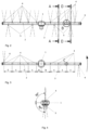
- FIG. 1 rotor of the invention in axonometric view
- FIG. 2 rotor of the invention, side view
- FIG. 3 rotor of the invention, top view, with illustration of distances between individual upper boreholes;
- FIG. 4 rotor of the invention, side view, with illustration and position of a jet from the boreholes facing upwards and the boreholes facing downwards;
- FIG. 5 Detail B of a leg of the rotor of the invention with illustration of the boreholes facing upwards;
- FIG. 6 Detail C of a leg of the rotor of the invention with illustration of the boreholes facing upwards;
- FIG. 7 view A-A of the cross-section of a leg of the rotor of the invention with illustration of a borehole facing upwards;
- FIG. 8 view D-D of the cross-section of a leg of the rotor of the invention with illustration of a borehole facing downwards.
- FIG. 1 shows a rotor for a cleaning machine of the invention in axonometric view.
- the rotor comprises two legs 2 , 3 in the form of a circular tube which are arranged on a rotary base 1 , said legs being provided with boreholes for the discharge of water solutions/liquids, more precisely boreholes 4 facing upwards and boreholes 5 facing downwards.
- the ends of legs 2 , 3 of the rotor are further provided with side boreholes 6 used to drive said rotor.
- the boreholes 4 and 5 for the discharge of water solutions/liquid from the rotor are formed on the legs 2 , 3 in the same line, such that the boreholes 4 facing upwards and the boreholes 5 facing downwards are oriented in a way that the outlet jets from the boreholes 4 facing upwards act vertically upwards and the jects from the boreholes 5 facing downwards act vertically downwards, i. e. in a direction 90° with respect to the axis of the legs 2 , 3 ( FIG. 4 ).
- the boreholes 4 facing upwards are distributed on the leg 2 at distances c from each other, wherein the first borehole 4 , viewed from the top view on the rotor, on the leg 2 is distant from the centre of the rotary base 1 for a distance a, while the first borehole 4 , viewed from the top view on the rotor, on the leg 3 is distant from the centre of the rotary base 1 for a distance b.
- the boreholes 5 facing downwards are arranged on the legs 2 , 3 at half the distance c and lie between and exactly 180° opposite the boreholes 4 facing upwards.
- the boreholes 5 facing downwards serve to spray the chamber walls or to carry out the so-called self-cleaning of the device, what is required in the pharmaceutical industry and should be proved by special procedures.
- the boreholes 4 facing upwards are formed by working the material outwards on the spot of tubes of the legs 2 , 3 , where a discharge spot (outlet from the tube) is then formed, such that the shape of the discharge spots—boreholes 4 facing upwards are of elliptical shape, namely following the equation y ⁇ 1.5 x wherein the value y equals the longer distance of the borehole 4 in the form of an ellipse, the value x equals the shorter distance of the borehole 4 in the form of an ellipse ( FIGS. 5 , 6 ).
- the elliptical shape of the outlet jet from the boreholes 4 facing upwards provides for a larger contact surface to be cleaned on the objects in the cleaning machine. In this way, a smaller number of discharge spots are required and better efficiency of the rotary rotor is achieved.
- the boreholes 5 facing downwards are formed precisely 180° opposite the boreholes 4 facing upwards and are made by the same technological method only that they have a circular shape.
- the boreholes 4 , 5 in the legs 2 , 3 having the shape of a circular tube are formed by a technological method of drawing that provides for unchanged superficial roughness of the interior of the tube, in which the medium flows, and allows a considerably higher flow rate of the outflowing medium compared to the embodiments, in which a base is welded onto a tube and a nozzle screwed into said base.
Landscapes
- Cleaning By Liquid Or Steam (AREA)
- Washing And Drying Of Tableware (AREA)
Abstract
Description
b=a+c/2
In this way, the
y≥1.5x
wherein the value y equals the longer distance of the
Claims (5)
(b)=(a)+(c)/2.
Applications Claiming Priority (3)
| Application Number | Priority Date | Filing Date | Title |
|---|---|---|---|
| SI201700219A SI25470A (en) | 2017-07-26 | 2017-07-26 | Dishwasher rotor |
| SIP-201700219 | 2017-07-26 | ||
| PCT/SI2018/000013 WO2019022677A1 (en) | 2017-07-26 | 2018-06-20 | Rotor for a cleaning machine |
Publications (2)
| Publication Number | Publication Date |
|---|---|
| US20200229673A1 US20200229673A1 (en) | 2020-07-23 |
| US11684233B2 true US11684233B2 (en) | 2023-06-27 |
Family
ID=63244939
Family Applications (1)
| Application Number | Title | Priority Date | Filing Date |
|---|---|---|---|
| US16/633,381 Active 2039-11-16 US11684233B2 (en) | 2017-07-26 | 2018-06-20 | Rotor for a cleaning machine |
Country Status (6)
| Country | Link |
|---|---|
| US (1) | US11684233B2 (en) |
| EP (1) | EP3658291B1 (en) |
| DK (1) | DK3658291T3 (en) |
| ES (1) | ES2906123T3 (en) |
| SI (1) | SI25470A (en) |
| WO (1) | WO2019022677A1 (en) |
Citations (5)
| Publication number | Priority date | Publication date | Assignee | Title |
|---|---|---|---|---|
| US2557206A (en) | 1946-03-21 | 1951-06-19 | Scovill Manufacturing Co | Sprinkler |
| US4405087A (en) | 1979-12-12 | 1983-09-20 | Mata Garza Antonio | Fluid mixing technique |
| EP0174758A2 (en) | 1984-09-12 | 1986-03-19 | Premark Feg Corporation | Wash arm and method and apparatus for forming the same |
| WO1995009696A1 (en) | 1993-10-05 | 1995-04-13 | Oscar Wilje | A method, device and composition in material spraying |
| US20090114741A1 (en) * | 2007-11-02 | 2009-05-07 | Steris Inc. | Nozzle assembly for a washer |
-
2017
- 2017-07-26 SI SI201700219A patent/SI25470A/en active IP Right Grant
-
2018
- 2018-06-20 US US16/633,381 patent/US11684233B2/en active Active
- 2018-06-20 ES ES18755938T patent/ES2906123T3/en active Active
- 2018-06-20 DK DK18755938.0T patent/DK3658291T3/en active
- 2018-06-20 EP EP18755938.0A patent/EP3658291B1/en active Active
- 2018-06-20 WO PCT/SI2018/000013 patent/WO2019022677A1/en not_active Ceased
Patent Citations (6)
| Publication number | Priority date | Publication date | Assignee | Title |
|---|---|---|---|---|
| US2557206A (en) | 1946-03-21 | 1951-06-19 | Scovill Manufacturing Co | Sprinkler |
| US4405087A (en) | 1979-12-12 | 1983-09-20 | Mata Garza Antonio | Fluid mixing technique |
| EP0174758A2 (en) | 1984-09-12 | 1986-03-19 | Premark Feg Corporation | Wash arm and method and apparatus for forming the same |
| WO1995009696A1 (en) | 1993-10-05 | 1995-04-13 | Oscar Wilje | A method, device and composition in material spraying |
| US20090114741A1 (en) * | 2007-11-02 | 2009-05-07 | Steris Inc. | Nozzle assembly for a washer |
| WO2009058620A1 (en) | 2007-11-02 | 2009-05-07 | Steris Inc. | Nozzle assembly for a washer |
Also Published As
| Publication number | Publication date |
|---|---|
| EP3658291A1 (en) | 2020-06-03 |
| WO2019022677A1 (en) | 2019-01-31 |
| EP3658291B1 (en) | 2021-10-27 |
| DK3658291T3 (en) | 2022-01-24 |
| ES2906123T3 (en) | 2022-04-13 |
| US20200229673A1 (en) | 2020-07-23 |
| SI25470A (en) | 2019-01-31 |
Similar Documents
| Publication | Publication Date | Title |
|---|---|---|
| JP5388613B2 (en) | High pressure cleaning liquid jet cleaning system | |
| JP6628210B2 (en) | Shower equipment | |
| CN105564880A (en) | Conveying device for potato chip production | |
| US11684233B2 (en) | Rotor for a cleaning machine | |
| CN102029230B (en) | Reciprocating linear motion jet flow generator and its application | |
| JP6442048B2 (en) | Two-fluid nozzle | |
| JP2017192380A (en) | Vegetable washing apparatus and vegetable washing system using the same | |
| CN206882252U (en) | Nozzle and the novel foam wash mill using the nozzle | |
| CN105532509B (en) | Egg cleaner and its cleaning process | |
| JP5463442B2 (en) | Drying equipment after washing food containers | |
| CN105594624A (en) | Egg washing machine | |
| JP2010274245A (en) | Cleaning device, drying device and cleaning system | |
| CN211322960U (en) | A fruit and vegetable cleaning device | |
| CN104382200A (en) | Brush-roll fruit and vegetable cleaning device | |
| KR102663445B1 (en) | Method for processing objects and apparatus for carrying out this method | |
| JP5084050B2 (en) | Cleaning method for small-diameter holes and bag holes on the surface of goods | |
| CN206356305U (en) | A kind of cleaning device with spray function | |
| CN105249499A (en) | Bamboo shoot cleaning device | |
| KR102361430B1 (en) | Apparatus for cleaning coupler | |
| EP3836824A2 (en) | A dishwasher with improved washing performance | |
| TW201829067A (en) | Spray bar design for uniform liquid flow distribution on a substrate | |
| JP2020506724A (en) | Apparatus and method for cleaning shell eggs | |
| CN204162033U (en) | Cleaning feedway | |
| CN204157617U (en) | There is the conveying device of cleaning function | |
| JP2007061733A (en) | Ultrasonic-wave cleaning nozzle, its design method and ultrasonic-wave cleaning method |
Legal Events
| Date | Code | Title | Description |
|---|---|---|---|
| FEPP | Fee payment procedure |
Free format text: ENTITY STATUS SET TO UNDISCOUNTED (ORIGINAL EVENT CODE: BIG.); ENTITY STATUS OF PATENT OWNER: SMALL ENTITY |
|
| AS | Assignment |
Owner name: BRINOX D.O.O., SLOVENIA Free format text: ASSIGNMENT OF ASSIGNORS INTEREST;ASSIGNOR:VENCELJ, BO?TJAN;REEL/FRAME:051616/0486 Effective date: 20200124 |
|
| FEPP | Fee payment procedure |
Free format text: ENTITY STATUS SET TO SMALL (ORIGINAL EVENT CODE: SMAL); ENTITY STATUS OF PATENT OWNER: SMALL ENTITY |
|
| STPP | Information on status: patent application and granting procedure in general |
Free format text: APPLICATION DISPATCHED FROM PREEXAM, NOT YET DOCKETED |
|
| STPP | Information on status: patent application and granting procedure in general |
Free format text: DOCKETED NEW CASE - READY FOR EXAMINATION |
|
| STPP | Information on status: patent application and granting procedure in general |
Free format text: NON FINAL ACTION MAILED |
|
| STPP | Information on status: patent application and granting procedure in general |
Free format text: RESPONSE TO NON-FINAL OFFICE ACTION ENTERED AND FORWARDED TO EXAMINER |
|
| STPP | Information on status: patent application and granting procedure in general |
Free format text: FINAL REJECTION MAILED |
|
| STPP | Information on status: patent application and granting procedure in general |
Free format text: RESPONSE AFTER FINAL ACTION FORWARDED TO EXAMINER |
|
| STCF | Information on status: patent grant |
Free format text: PATENTED CASE |