US11660825B2 - Manufacturing device of package and manufacturing method of package - Google Patents
Manufacturing device of package and manufacturing method of package Download PDFInfo
- Publication number
- US11660825B2 US11660825B2 US17/169,880 US202117169880A US11660825B2 US 11660825 B2 US11660825 B2 US 11660825B2 US 202117169880 A US202117169880 A US 202117169880A US 11660825 B2 US11660825 B2 US 11660825B2
- Authority
- US
- United States
- Prior art keywords
- sealed portion
- sheet
- sealing
- thickness
- good
- Prior art date
- Legal status (The legal status is an assumption and is not a legal conclusion. Google has not performed a legal analysis and makes no representation as to the accuracy of the status listed.)
- Active
Links
Images


Classifications
-
- B—PERFORMING OPERATIONS; TRANSPORTING
- B29—WORKING OF PLASTICS; WORKING OF SUBSTANCES IN A PLASTIC STATE IN GENERAL
- B29C—SHAPING OR JOINING OF PLASTICS; SHAPING OF MATERIAL IN A PLASTIC STATE, NOT OTHERWISE PROVIDED FOR; AFTER-TREATMENT OF THE SHAPED PRODUCTS, e.g. REPAIRING
- B29C65/00—Joining or sealing of preformed parts, e.g. welding of plastics materials; Apparatus therefor
- B29C65/82—Testing the joint
- B29C65/8253—Testing the joint by the use of waves or particle radiation, e.g. visual examination, scanning electron microscopy, or X-rays
-
- B—PERFORMING OPERATIONS; TRANSPORTING
- B29—WORKING OF PLASTICS; WORKING OF SUBSTANCES IN A PLASTIC STATE IN GENERAL
- B29C—SHAPING OR JOINING OF PLASTICS; SHAPING OF MATERIAL IN A PLASTIC STATE, NOT OTHERWISE PROVIDED FOR; AFTER-TREATMENT OF THE SHAPED PRODUCTS, e.g. REPAIRING
- B29C66/00—General aspects of processes or apparatus for joining preformed parts
- B29C66/01—General aspects dealing with the joint area or with the area to be joined
- B29C66/05—Particular design of joint configurations
- B29C66/10—Particular design of joint configurations particular design of the joint cross-sections
- B29C66/11—Joint cross-sections comprising a single joint-segment, i.e. one of the parts to be joined comprising a single joint-segment in the joint cross-section
- B29C66/112—Single lapped joints
- B29C66/1122—Single lap to lap joints, i.e. overlap joints
-
- B—PERFORMING OPERATIONS; TRANSPORTING
- B29—WORKING OF PLASTICS; WORKING OF SUBSTANCES IN A PLASTIC STATE IN GENERAL
- B29C—SHAPING OR JOINING OF PLASTICS; SHAPING OF MATERIAL IN A PLASTIC STATE, NOT OTHERWISE PROVIDED FOR; AFTER-TREATMENT OF THE SHAPED PRODUCTS, e.g. REPAIRING
- B29C66/00—General aspects of processes or apparatus for joining preformed parts
- B29C66/01—General aspects dealing with the joint area or with the area to be joined
- B29C66/05—Particular design of joint configurations
- B29C66/20—Particular design of joint configurations particular design of the joint lines, e.g. of the weld lines
- B29C66/21—Particular design of joint configurations particular design of the joint lines, e.g. of the weld lines said joint lines being formed by a single dot or dash or by several dots or dashes, i.e. spot joining or spot welding
-
- B—PERFORMING OPERATIONS; TRANSPORTING
- B29—WORKING OF PLASTICS; WORKING OF SUBSTANCES IN A PLASTIC STATE IN GENERAL
- B29C—SHAPING OR JOINING OF PLASTICS; SHAPING OF MATERIAL IN A PLASTIC STATE, NOT OTHERWISE PROVIDED FOR; AFTER-TREATMENT OF THE SHAPED PRODUCTS, e.g. REPAIRING
- B29C66/00—General aspects of processes or apparatus for joining preformed parts
- B29C66/01—General aspects dealing with the joint area or with the area to be joined
- B29C66/05—Particular design of joint configurations
- B29C66/20—Particular design of joint configurations particular design of the joint lines, e.g. of the weld lines
- B29C66/24—Particular design of joint configurations particular design of the joint lines, e.g. of the weld lines said joint lines being closed or non-straight
- B29C66/242—Particular design of joint configurations particular design of the joint lines, e.g. of the weld lines said joint lines being closed or non-straight said joint lines being closed, i.e. forming closed contours
- B29C66/2424—Particular design of joint configurations particular design of the joint lines, e.g. of the weld lines said joint lines being closed or non-straight said joint lines being closed, i.e. forming closed contours being a closed polygonal chain
- B29C66/24243—Particular design of joint configurations particular design of the joint lines, e.g. of the weld lines said joint lines being closed or non-straight said joint lines being closed, i.e. forming closed contours being a closed polygonal chain forming a quadrilateral
- B29C66/24244—Particular design of joint configurations particular design of the joint lines, e.g. of the weld lines said joint lines being closed or non-straight said joint lines being closed, i.e. forming closed contours being a closed polygonal chain forming a quadrilateral forming a rectangle
-
- B—PERFORMING OPERATIONS; TRANSPORTING
- B29—WORKING OF PLASTICS; WORKING OF SUBSTANCES IN A PLASTIC STATE IN GENERAL
- B29C—SHAPING OR JOINING OF PLASTICS; SHAPING OF MATERIAL IN A PLASTIC STATE, NOT OTHERWISE PROVIDED FOR; AFTER-TREATMENT OF THE SHAPED PRODUCTS, e.g. REPAIRING
- B29C66/00—General aspects of processes or apparatus for joining preformed parts
- B29C66/40—General aspects of joining substantially flat articles, e.g. plates, sheets or web-like materials; Making flat seams in tubular or hollow articles; Joining single elements to substantially flat surfaces
- B29C66/41—Joining substantially flat articles ; Making flat seams in tubular or hollow articles
- B29C66/43—Joining a relatively small portion of the surface of said articles
- B29C66/431—Joining the articles to themselves
- B29C66/4312—Joining the articles to themselves for making flat seams in tubular or hollow articles, e.g. transversal seams
- B29C66/43121—Closing the ends of tubular or hollow single articles, e.g. closing the ends of bags
-
- B—PERFORMING OPERATIONS; TRANSPORTING
- B29—WORKING OF PLASTICS; WORKING OF SUBSTANCES IN A PLASTIC STATE IN GENERAL
- B29C—SHAPING OR JOINING OF PLASTICS; SHAPING OF MATERIAL IN A PLASTIC STATE, NOT OTHERWISE PROVIDED FOR; AFTER-TREATMENT OF THE SHAPED PRODUCTS, e.g. REPAIRING
- B29C66/00—General aspects of processes or apparatus for joining preformed parts
- B29C66/70—General aspects of processes or apparatus for joining preformed parts characterised by the composition, physical properties or the structure of the material of the parts to be joined; Joining with non-plastics material
- B29C66/73—General aspects of processes or apparatus for joining preformed parts characterised by the composition, physical properties or the structure of the material of the parts to be joined; Joining with non-plastics material characterised by the intensive physical properties of the material of the parts to be joined, by the optical properties of the material of the parts to be joined, by the extensive physical properties of the parts to be joined, by the state of the material of the parts to be joined or by the material of the parts to be joined being a thermoplastic or a thermoset
- B29C66/733—General aspects of processes or apparatus for joining preformed parts characterised by the composition, physical properties or the structure of the material of the parts to be joined; Joining with non-plastics material characterised by the intensive physical properties of the material of the parts to be joined, by the optical properties of the material of the parts to be joined, by the extensive physical properties of the parts to be joined, by the state of the material of the parts to be joined or by the material of the parts to be joined being a thermoplastic or a thermoset characterised by the optical properties of the material of the parts to be joined, e.g. fluorescence, phosphorescence
- B29C66/7336—General aspects of processes or apparatus for joining preformed parts characterised by the composition, physical properties or the structure of the material of the parts to be joined; Joining with non-plastics material characterised by the intensive physical properties of the material of the parts to be joined, by the optical properties of the material of the parts to be joined, by the extensive physical properties of the parts to be joined, by the state of the material of the parts to be joined or by the material of the parts to be joined being a thermoplastic or a thermoset characterised by the optical properties of the material of the parts to be joined, e.g. fluorescence, phosphorescence at least one of the parts to be joined being opaque, transparent or translucent to visible light
- B29C66/73365—General aspects of processes or apparatus for joining preformed parts characterised by the composition, physical properties or the structure of the material of the parts to be joined; Joining with non-plastics material characterised by the intensive physical properties of the material of the parts to be joined, by the optical properties of the material of the parts to be joined, by the extensive physical properties of the parts to be joined, by the state of the material of the parts to be joined or by the material of the parts to be joined being a thermoplastic or a thermoset characterised by the optical properties of the material of the parts to be joined, e.g. fluorescence, phosphorescence at least one of the parts to be joined being opaque, transparent or translucent to visible light at least one of the parts to be joined being transparent or translucent to visible light
- B29C66/73366—General aspects of processes or apparatus for joining preformed parts characterised by the composition, physical properties or the structure of the material of the parts to be joined; Joining with non-plastics material characterised by the intensive physical properties of the material of the parts to be joined, by the optical properties of the material of the parts to be joined, by the extensive physical properties of the parts to be joined, by the state of the material of the parts to be joined or by the material of the parts to be joined being a thermoplastic or a thermoset characterised by the optical properties of the material of the parts to be joined, e.g. fluorescence, phosphorescence at least one of the parts to be joined being opaque, transparent or translucent to visible light at least one of the parts to be joined being transparent or translucent to visible light both parts to be joined being transparent or translucent to visible light
-
- B—PERFORMING OPERATIONS; TRANSPORTING
- B29—WORKING OF PLASTICS; WORKING OF SUBSTANCES IN A PLASTIC STATE IN GENERAL
- B29C—SHAPING OR JOINING OF PLASTICS; SHAPING OF MATERIAL IN A PLASTIC STATE, NOT OTHERWISE PROVIDED FOR; AFTER-TREATMENT OF THE SHAPED PRODUCTS, e.g. REPAIRING
- B29C66/00—General aspects of processes or apparatus for joining preformed parts
- B29C66/70—General aspects of processes or apparatus for joining preformed parts characterised by the composition, physical properties or the structure of the material of the parts to be joined; Joining with non-plastics material
- B29C66/73—General aspects of processes or apparatus for joining preformed parts characterised by the composition, physical properties or the structure of the material of the parts to be joined; Joining with non-plastics material characterised by the intensive physical properties of the material of the parts to be joined, by the optical properties of the material of the parts to be joined, by the extensive physical properties of the parts to be joined, by the state of the material of the parts to be joined or by the material of the parts to be joined being a thermoplastic or a thermoset
- B29C66/739—General aspects of processes or apparatus for joining preformed parts characterised by the composition, physical properties or the structure of the material of the parts to be joined; Joining with non-plastics material characterised by the intensive physical properties of the material of the parts to be joined, by the optical properties of the material of the parts to be joined, by the extensive physical properties of the parts to be joined, by the state of the material of the parts to be joined or by the material of the parts to be joined being a thermoplastic or a thermoset characterised by the material of the parts to be joined being a thermoplastic or a thermoset
- B29C66/7392—General aspects of processes or apparatus for joining preformed parts characterised by the composition, physical properties or the structure of the material of the parts to be joined; Joining with non-plastics material characterised by the intensive physical properties of the material of the parts to be joined, by the optical properties of the material of the parts to be joined, by the extensive physical properties of the parts to be joined, by the state of the material of the parts to be joined or by the material of the parts to be joined being a thermoplastic or a thermoset characterised by the material of the parts to be joined being a thermoplastic or a thermoset characterised by the material of at least one of the parts being a thermoplastic
- B29C66/73921—General aspects of processes or apparatus for joining preformed parts characterised by the composition, physical properties or the structure of the material of the parts to be joined; Joining with non-plastics material characterised by the intensive physical properties of the material of the parts to be joined, by the optical properties of the material of the parts to be joined, by the extensive physical properties of the parts to be joined, by the state of the material of the parts to be joined or by the material of the parts to be joined being a thermoplastic or a thermoset characterised by the material of the parts to be joined being a thermoplastic or a thermoset characterised by the material of at least one of the parts being a thermoplastic characterised by the materials of both parts being thermoplastics
-
- B—PERFORMING OPERATIONS; TRANSPORTING
- B29—WORKING OF PLASTICS; WORKING OF SUBSTANCES IN A PLASTIC STATE IN GENERAL
- B29C—SHAPING OR JOINING OF PLASTICS; SHAPING OF MATERIAL IN A PLASTIC STATE, NOT OTHERWISE PROVIDED FOR; AFTER-TREATMENT OF THE SHAPED PRODUCTS, e.g. REPAIRING
- B29C66/00—General aspects of processes or apparatus for joining preformed parts
- B29C66/80—General aspects of machine operations or constructions and parts thereof
- B29C66/84—Specific machine types or machines suitable for specific applications
- B29C66/849—Packaging machines
-
- B—PERFORMING OPERATIONS; TRANSPORTING
- B29—WORKING OF PLASTICS; WORKING OF SUBSTANCES IN A PLASTIC STATE IN GENERAL
- B29C—SHAPING OR JOINING OF PLASTICS; SHAPING OF MATERIAL IN A PLASTIC STATE, NOT OTHERWISE PROVIDED FOR; AFTER-TREATMENT OF THE SHAPED PRODUCTS, e.g. REPAIRING
- B29C66/00—General aspects of processes or apparatus for joining preformed parts
- B29C66/90—Measuring or controlling the joining process
- B29C66/95—Measuring or controlling the joining process by measuring or controlling specific variables not covered by groups B29C66/91 - B29C66/94
- B29C66/954—Measuring or controlling the joining process by measuring or controlling specific variables not covered by groups B29C66/91 - B29C66/94 by measuring or controlling the thickness of the parts to be joined
-
- B—PERFORMING OPERATIONS; TRANSPORTING
- B65—CONVEYING; PACKING; STORING; HANDLING THIN OR FILAMENTARY MATERIAL
- B65B—MACHINES, APPARATUS OR DEVICES FOR, OR METHODS OF, PACKAGING ARTICLES OR MATERIALS; UNPACKING
- B65B51/00—Devices for, or methods of, sealing or securing package folds or closures; Devices for gathering or twisting wrappers, or necks of bags
- B65B51/10—Applying or generating heat or pressure or combinations thereof
-
- B—PERFORMING OPERATIONS; TRANSPORTING
- B65—CONVEYING; PACKING; STORING; HANDLING THIN OR FILAMENTARY MATERIAL
- B65B—MACHINES, APPARATUS OR DEVICES FOR, OR METHODS OF, PACKAGING ARTICLES OR MATERIALS; UNPACKING
- B65B57/00—Automatic control, checking, warning, or safety devices
- B65B57/02—Automatic control, checking, warning, or safety devices responsive to absence, presence, abnormal feed, or misplacement of binding or wrapping material, containers, or packages
-
- G—PHYSICS
- G01—MEASURING; TESTING
- G01B—MEASURING LENGTH, THICKNESS OR SIMILAR LINEAR DIMENSIONS; MEASURING ANGLES; MEASURING AREAS; MEASURING IRREGULARITIES OF SURFACES OR CONTOURS
- G01B11/00—Measuring arrangements characterised by the use of optical techniques
- G01B11/02—Measuring arrangements characterised by the use of optical techniques for measuring length, width or thickness
- G01B11/06—Measuring arrangements characterised by the use of optical techniques for measuring length, width or thickness for measuring thickness ; e.g. of sheet material
-
- G—PHYSICS
- G01—MEASURING; TESTING
- G01N—INVESTIGATING OR ANALYSING MATERIALS BY DETERMINING THEIR CHEMICAL OR PHYSICAL PROPERTIES
- G01N21/00—Investigating or analysing materials by the use of optical means, i.e. using sub-millimetre waves, infrared, visible or ultraviolet light
- G01N21/84—Systems specially adapted for particular applications
- G01N21/8422—Investigating thin films, e.g. matrix isolation method
-
- G—PHYSICS
- G01—MEASURING; TESTING
- G01N—INVESTIGATING OR ANALYSING MATERIALS BY DETERMINING THEIR CHEMICAL OR PHYSICAL PROPERTIES
- G01N21/00—Investigating or analysing materials by the use of optical means, i.e. using sub-millimetre waves, infrared, visible or ultraviolet light
- G01N21/84—Systems specially adapted for particular applications
- G01N21/88—Investigating the presence of flaws or contamination
- G01N21/89—Investigating the presence of flaws or contamination in moving material, e.g. running paper or textiles
- G01N21/892—Investigating the presence of flaws or contamination in moving material, e.g. running paper or textiles characterised by the flaw, defect or object feature examined
- G01N21/896—Optical defects in or on transparent materials, e.g. distortion, surface flaws in conveyed flat sheet or rod
-
- G—PHYSICS
- G01—MEASURING; TESTING
- G01N—INVESTIGATING OR ANALYSING MATERIALS BY DETERMINING THEIR CHEMICAL OR PHYSICAL PROPERTIES
- G01N21/00—Investigating or analysing materials by the use of optical means, i.e. using sub-millimetre waves, infrared, visible or ultraviolet light
- G01N21/84—Systems specially adapted for particular applications
- G01N21/88—Investigating the presence of flaws or contamination
- G01N21/90—Investigating the presence of flaws or contamination in a container or its contents
- G01N21/9054—Inspection of sealing surface and container finish
-
- B—PERFORMING OPERATIONS; TRANSPORTING
- B29—WORKING OF PLASTICS; WORKING OF SUBSTANCES IN A PLASTIC STATE IN GENERAL
- B29C—SHAPING OR JOINING OF PLASTICS; SHAPING OF MATERIAL IN A PLASTIC STATE, NOT OTHERWISE PROVIDED FOR; AFTER-TREATMENT OF THE SHAPED PRODUCTS, e.g. REPAIRING
- B29C65/00—Joining or sealing of preformed parts, e.g. welding of plastics materials; Apparatus therefor
- B29C65/02—Joining or sealing of preformed parts, e.g. welding of plastics materials; Apparatus therefor by heating, with or without pressure
-
- B—PERFORMING OPERATIONS; TRANSPORTING
- B29—WORKING OF PLASTICS; WORKING OF SUBSTANCES IN A PLASTIC STATE IN GENERAL
- B29C—SHAPING OR JOINING OF PLASTICS; SHAPING OF MATERIAL IN A PLASTIC STATE, NOT OTHERWISE PROVIDED FOR; AFTER-TREATMENT OF THE SHAPED PRODUCTS, e.g. REPAIRING
- B29C66/00—General aspects of processes or apparatus for joining preformed parts
- B29C66/70—General aspects of processes or apparatus for joining preformed parts characterised by the composition, physical properties or the structure of the material of the parts to be joined; Joining with non-plastics material
- B29C66/71—General aspects of processes or apparatus for joining preformed parts characterised by the composition, physical properties or the structure of the material of the parts to be joined; Joining with non-plastics material characterised by the composition of the plastics material of the parts to be joined
-
- B—PERFORMING OPERATIONS; TRANSPORTING
- B29—WORKING OF PLASTICS; WORKING OF SUBSTANCES IN A PLASTIC STATE IN GENERAL
- B29C—SHAPING OR JOINING OF PLASTICS; SHAPING OF MATERIAL IN A PLASTIC STATE, NOT OTHERWISE PROVIDED FOR; AFTER-TREATMENT OF THE SHAPED PRODUCTS, e.g. REPAIRING
- B29C66/00—General aspects of processes or apparatus for joining preformed parts
- B29C66/80—General aspects of machine operations or constructions and parts thereof
- B29C66/84—Specific machine types or machines suitable for specific applications
- B29C66/841—Machines or tools adaptable for making articles of different dimensions or shapes or for making joints of different dimensions
- B29C66/8412—Machines or tools adaptable for making articles of different dimensions or shapes or for making joints of different dimensions of different length, width or height
-
- G—PHYSICS
- G01—MEASURING; TESTING
- G01N—INVESTIGATING OR ANALYSING MATERIALS BY DETERMINING THEIR CHEMICAL OR PHYSICAL PROPERTIES
- G01N21/00—Investigating or analysing materials by the use of optical means, i.e. using sub-millimetre waves, infrared, visible or ultraviolet light
- G01N21/84—Systems specially adapted for particular applications
- G01N21/8422—Investigating thin films, e.g. matrix isolation method
- G01N2021/8438—Mutilayers
-
- G—PHYSICS
- G01—MEASURING; TESTING
- G01N—INVESTIGATING OR ANALYSING MATERIALS BY DETERMINING THEIR CHEMICAL OR PHYSICAL PROPERTIES
- G01N21/00—Investigating or analysing materials by the use of optical means, i.e. using sub-millimetre waves, infrared, visible or ultraviolet light
- G01N21/84—Systems specially adapted for particular applications
- G01N21/88—Investigating the presence of flaws or contamination
- G01N21/95—Investigating the presence of flaws or contamination characterised by the material or shape of the object to be examined
- G01N21/958—Inspecting transparent materials or objects, e.g. windscreens
Definitions
- the present disclosure relates to a manufacturing device and a manufacturing method of obtaining a package by packing a predetermined work with a predetermined sheet.
- a package with a predetermined work for example, commodity, a food article, a machine component or the like placed and packed in a sheet made of, for example, a resin such as polyethylene may be obtained by packing the work with the sheet and thermally welding the sheet.
- the package may be manufactured by a packaging device (a manufacturing device of a package) equipped with, for example, a sealing unit configured to thermally weld the sheet.
- a sealed portion formed by thermal welding is likely to have a sealing failure, for example, insufficient welding of the sheets.
- a conventionally known configuration of an inspection device used to perform an inspection for such a sealing failure includes a laser light source configured to irradiate a sealed portion with laser beam, a light detector configured to detect the quantity of light transmitted through the sealed portion, and a light shielding plate placed between the sealed portion and the light detector and provided with a hole formed to allow for passage of the laser beam (as described in, for example, Patent Literature 1).
- the inspection device described in Patent Literature 1 determines the good/poor quality of sealing with regard to the sealed portion, based on the quantity of light detected by the light detector. More specifically, in the case of good sealing quality, a plurality of sheets forming the sealed portion are in close contact with each other and tightly adhere to each other, so that the emitted laser beam almost directly passes through the sealed portion. Accordingly, a relatively large quantity of light passing through the hole of the light shielding plate and entering the light detector indicates the good sealing quality. In the case of poor sealing quality, on the other hand, there is a clearance between a plurality of sheets forming the sealed portion, so that the emitted laser beam is reflected, refracted, and scattered when the light enters the sheet or goes out of the sheet. As a result, the light transmitted through the sealed portion is scattered over a wide range. Accordingly, a relatively small quantity of light passing through the hole of the light shielding plate and entering the light detector indicates the poor sealing quality.
- Patent Literature 1 JP No. S62-276444A
- one or more embodiments of the present invention provide a manufacturing device of a package and a manufacturing method of a package that perform an inspection for the good/poor quality of sealing with the higher accuracy.
- One or more embodiments of the present invention provide a manufacturing device of a package that is obtained by packing a predetermined work with a sheet made of a resin.
- the manufacturing device of the package comprises a sealing unit configured to thermally weld overlapping parts of the sheet; and an inspection unit configured to perform an inspection for good/poor quality of sealing with regard to a sealed portion of the sheet formed by thermal welding by the sealing unit.
- the sealing unit is configured to perform the thermal welding such as to make a thickness of the sealed portion smaller than a total thickness of the overlapping parts of the sheet as an object to be thermally welded prior to the thermal welding.
- the inspection unit comprises a thickness information obtaining unit configured to obtain thickness information corresponding to the thickness of the sealed portion; and a good/poor quality judgment unit configured to determine good/poor quality of sealing with regard to the sealed portion, based on the thickness information obtained by the thickness information obtaining unit.
- the “thickness information” may be a thickness itself or may be any of various information varying with a variation in thickness.
- the sealing unit performs thermal welding such as to make the thickness of the sealed portion smaller than the total thickness of the overlapping parts of the sheet corresponding to the sealed portion prior to thermal welding. Accordingly, the sealed portion that is appropriately welded to have a good sealing quality has a sufficiently smaller thickness than the total thickness.
- the sealed portion that is not sufficiently welded to have a poor sealing quality has a thickness equivalent to or even larger than the total thickness (for example, in the case where there is a clearance between the overlapping parts of the sheet).
- the sealing unit performs thermal welding such as to correlate the good/poor quality of sealing to the thickness of the sealed portion.
- the thickness information obtaining unit obtains the thickness information corresponding to the thickness of the sealed portion, and the good/poor quality judgment unit determines the good/poor quality of sealing, based on the thickness information. For example, in the case where there is no clearance between the overlapping parts of the sheet that form the sealed portion and where the sheet is sufficiently welded, the sealed portion becomes relatively thin. The good/poor quality judgment unit accordingly determines the good quality of sealing. In another example, in the case where there is a clearance between the overlapping parts of the sheet that form the sealed portion or where the overlapping parts of the sheet are not sufficiently welded, on the other hand, the sealed portion becomes relatively thick. The good/poor quality judgment unit accordingly determines the poor quality of sealing. As described above, the good/poor quality of sealing is correlated to the thickness of the sealed portion. The configuration of performing the good/poor quality judgment based on the thickness information thus enables the good/poor quality of sealing to be determined with the higher accuracy.
- the sealing unit may be configured to perform thermal welding such as to make the thickness of a sealed portion smaller than the total thickness of the overlapping parts of the sheet as an object to be thermally welded prior to the thermal welding and larger than a predetermined limit thickness.
- the good/poor quality judgment unit may be configured to determine the poor sealing quality when the sealed portion is excessively thin. This configuration allows for detection of a sealing failure or the like due to, for example, a damage of the sealed portion and thereby further enhances the accuracy of inspection.
- the thickness information obtaining unit may comprise an irradiation unit configured to irradiate the sheet with ultraviolet light; and an imaging unit configured to take an image of ultraviolet light transmitted through the sheet in a state that the sheet including the sealed portion is irradiated with the ultraviolet light by the irradiation unit.
- the thickness information obtaining unit may be configured to obtain information with regard to a quantity of transmitted light of the sealed portion, based on image data obtained by the imaging unit, as the thickness information.
- the good/poor quality judgment unit may determine good/poor quality of sealing with regard to the sealed portion, based on the information with regard to the quantity of transmitted light.
- the configuration of one or more embodiments obtains the information with regard to the quantity of transmitted light with regard to the sealed portion, based on the image data obtained by the imaging unit (for example, a luminance value or the like of the sealed portion in the image data).
- a logarithmic value of an ultraviolet light transmittance is generally proportional to the thickness of the sheet, and the ultraviolet light transmittance is inversely proportional to some power of the thickness of the sheet. Accordingly, the magnitude relation of the light quantity of ultraviolet light transmitted through the sheet (quantity of transmitted light) depends upon the thickness of the sheet.
- the configuration of obtaining the information with regard to the quantity of transmitted light as the thickness information accordingly enables the thickness of the sheet to be figured out more accurately. This enables the good/poor quality of sealing to be determined with the higher accuracy.
- the configuration of using the image data enables the thickness of the entire area of the sealed portion to be figured out. This configuration accordingly enables a sealing failure occurring in only a narrow part of the sealed portion to be found out and further enhances the accuracy of inspection.
- One or more embodiments of the present invention provide a manufacturing method of a package that is obtained by packing a predetermined work with a sheet made of a resin.
- the manufacturing method of the package comprises a sealing process of thermally welding overlapping parts of the sheet; and an inspection process of performing an inspection for good/poor quality of sealing with regard to a sealed portion of the sheet formed by thermal welding in the sealing process.
- the sealing process performs the thermal welding such as to make a thickness of the sealed portion smaller than a total thickness of the overlapping parts of the sheet as an object to be thermally welded prior to the thermal welding.
- the inspection process comprises a thickness information obtaining process of obtaining thickness information corresponding to the thickness of the sealed portion; and a good/poor quality judgment process of determining good/poor quality of sealing with regard to the sealed portion, based on the thickness information obtained in the thickness information obtaining process.
- the thickness information obtaining process may comprise performing an imaging process of taking an image of ultraviolet light transmitted through the sheet in a state that the sheet including the sealed portion is irradiated with ultraviolet light.
- the thickness information obtaining process may obtain information with regard to a quantity of transmitted light of the sealed portion, based on image data obtained in the imaging process, as the thickness information.
- the good/poor quality judgment process may determine good/poor quality of sealing with regard to the sealed portion, based on the information with regard to the quantity of transmitted light.
- FIG. 1 is a perspective view illustrating a package
- FIG. 2 is an enlarged view illustrating a sheet placed in an upper portion of the package
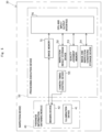
- FIG. 3 is a block diagram illustrating the schematic configuration of a packaging device
- FIG. 4 is a block diagram illustrating the schematic configuration of a packaging mechanism
- FIG. 5 is a block diagram illustrating the electrical configuration of an inspection device
- FIG. 6 is a schematic diagram illustrating the schematic configuration of the inspection device
- FIG. 7 is a schematic diagram illustrating one example of image data.
- FIG. 8 is a flowchart showing a packaging process.
- a package 1 manufactured by a packaging device is described first.
- the package 1 includes a packing bag 2 to pack a plurality of works 8 (rolls of paper according to one or more embodiments.
- the packing bag 2 is formed by thermally welding respective ends of a sheet 3 in a cylindrical shape and has welded parts 4 and 5 in an upper portion and a lower portion thereof.
- the sheet 3 is made of a transparent or translucent thermoplastic resin (for example, polyethylene or the like).
- the welded parts 4 and 5 have sealed portions 6 .
- the sealed portion 6 is formed by stacking and thermally welding at least two sheet parts out of the respective parts of the sheet 3 forming a front face, a rear face and both side faces of the packing bag 2 .
- a plurality of the sealed portions 6 are provided to be respectively formed in a rectangular shape in front view and to be arranged in a regular pattern in a horizontal direction and in a vertical direction.
- the respective sealed portions 6 in the welded part 4 are arranged in two horizontal seal lines arrayed in a horizontal direction and five vertical seal lines arrayed in a vertical direction.
- the vertical seal lines are placed at intervals in the horizontal direction between the horizontal seal lines.
- the respective sealed portions 6 in the welded part 4 are arranged to be separate from each other. As a result, an upper end of the packing bag 2 is formed breathable.
- a pair of finger catchers 7 that are to be caught by fingers of a user are provided on a left side and a right side of the vertical seal line located in the middle in the upper portion of the packing bag 2 .
- Each of the finger catchers 7 has a cut line in an approximately elliptical shape. When the user cuts the sheet 3 along the cut lines, through holes are formed in the upper portion of the packing bag 2 . The user is allowed to insert the fingers into the through holes and carry the works 8 .
- the sealed portion 6 is in a linear shape continuously extended along the horizontal direction.
- the packaging device 10 includes a packaging mechanism 20 and an inspection device 30 .
- the manufacturing device of the package is configured by the packaging device 10
- the inspection unit is configured by the inspection device 30 .
- the packaging mechanism 20 includes a sheet feed mechanism 21 , a bag-making mechanism 22 , a filling mechanism 23 and a sealing mechanism 24 .
- the bag-making mechanism 22 and the sealing mechanism 24 correspond to the sealing unit.
- the sheet feed mechanism 21 rotatably supports a sheet roll of the wound sheet 3 that is formed in advance in the cylindrical shape.
- the sheet feed mechanism 21 inflates the sheet 3 in the cylindrical shape with compressed air or the like, folds two parts opposed to each other of the sheet 3 in the cylindrical shape 3 inward of the sheet 3 , and places the sheet 3 between a pair of rollers (not shown) to feed out the sheet 3 .
- This forms the sheet 3 in a belt-like shape having gussets on respective ends in a width direction thereof.
- the sheet 3 formed in the belt-like shape is fed to the bag-making mechanism 22 .
- the bag-making mechanism 22 thermally welds an end of the sheet 3 in the belt-like shape fed from the sheet feed mechanism 21 and cuts the sheet by a predetermined length. This forms the welded part 5 (sealed portions 6 ) placed in the lower portion of the packing bag 2 , so as to form the sheet 3 in a bag shape.
- the predetermined length may be varied appropriately corresponding to the number of the works 8 and the size of the works 8 placed in the packing bag 2 .
- the filling mechanism 23 serves to array a predetermined number of the works 8 and fill the arrayed works 8 into the sheet 3 in the bag shape produced by the bag-making mechanism 22 .
- the filling mechanism 23 is comprised of, for example, a stacking mechanism configured to stack the predetermined number of the works 8 in an inverted attitude, a bucket configured to hold the sheet in the bag shape in an open state, and a pusher configured to push the works 8 in the inverted attitude into the sheet 3 in the bag shape held in the open state by the bucket (none of the components are shown).
- the sealing mechanism 24 gusset-folds the opening of the sheet 3 in the bag shape with the works 8 packed (filled with the works 8 ), lays the parts of the sheet 3 over each other, and clamps the overlapping parts of the sheet 3 by a predetermined sealer (not shown), so as to thermally weld the overlapping parts of the sheet 3 .
- the sealing mechanism 24 forms the welded part 4 (the sealed portions 6 ) placed in the upper portion of the packing bag 2 .
- the operations of the bag-making mechanism 22 and the sealing mechanism 24 are set to thermally weld the overlapping parts of the sheet 3 such as to make the thickness of the formed sealed portions 6 smaller than the total thickness of the overlapping parts of the sheet 3 , which are the object to be thermally welded, prior to thermal welding. Accordingly, the sealed portion 6 that is appropriately welded to have a good sealing quality has a sufficiently smaller thickness than the total thickness. The sealed portion 6 that is not sufficiently welded to have a poor sealing quality, on the other hand, has a thickness equivalent to or even larger than the total thickness (for example, in the case where there is a clearance between the overlapping parts of the sheet 3 ). As described above, the bag-making mechanism 22 and the sealing mechanism 24 perform thermal welding such as to correlate the good/poor quality of sealing to the thickness of the sealed portion 6 .
- the package 1 is obtained by cutting a non-required part of the sheet by a predetermined non-required part cutting device (not shown) and forming the finger catchers 7 by a predetermined cutting line forming device (not shown).
- a modified configuration may form the finger catchers 7 in the process of thermal welding by the sealing mechanism 24 .
- the inspection device 30 performs an inspection for the good/poor quality of sealing with regard to the sealed portions 6 of the sheet 3 thermally welded by the bag-making mechanism 22 and the sealing mechanism 24 .
- the inspection device 30 includes a thickness information obtaining module 40 and a processing execution device 50 .
- the thickness information obtaining module corresponds to the thickness information obtaining unit
- the processing execution device 50 corresponds to the good/poor quality judgment unit.
- the thickness information obtaining module 40 is configured to obtain thickness information regarding the thickness of the sealed portion 6 and includes an illumination device 41 and an imaging device 42 .
- the illumination device 41 corresponds to the irradiation unit
- the imaging device 42 corresponds to the imaging unit.
- the illumination device 41 is placed below the sheet 3 including the sealed portions 6 that are objects to be inspected and includes a light source 41 A comprised of, for example, an LED to emit ultraviolet light (for example, light having wavelength of 200 to 380 nm) and a diffusion plate 41 B placed between the light source 41 A and the sheet 3 and comprised of, for example, ground glass.
- the illumination device 41 is configured to radiate the diffused ultraviolet light toward the sheet 3 including the sealed portions 6 .
- the imaging device 42 is provided on a side opposite to the illumination device 41 across the sheet 3 .
- a CCD camera having sensitivity to at least ultraviolet light is employed as the imaging device 42 .
- the imaging device 42 is, however, not limited to this example, but a CMOS camera may be employed.
- the imaging device 42 is configured to take a two-dimensional image of the ultraviolet light transmitted through the sheet 3 when the sheet 3 including the sealed portions 6 is irradiated with the ultraviolet light emitted from the illumination device 41 .
- Image data (luminance image data) obtained by imaging with the imaging device 42 is converted into a digital signal (image signal) inside of the imaging device 42 and is input in the form of digital signal into the processing execution device 50 .
- the image data includes information with regard to the quantities of transmitted light of the sealed portions 6 (luminance values of the sealed portions 6 according to one or more embodiments) as the thickness information.
- An imaging range of the imaging device 42 is set to a range that covers at least the entire areas of the welded parts 4 and 5 . According to one or more embodiments, the imaging device 42 is configured to respectively take images of the welded part 4 and the welded part 5 and obtain respective image data with regard to the welded part 4 and with regard to the welded part 5 .
- the processing execution device 50 is configured to determine the good/poor quality of the sealed portions 6 , based on the image data obtained by the imaging device 42 (more specifically, the information with regard to the quantities of transmitted light of the sealed portions 6 as the thickness information obtained from the image data).
- the processing execution device 50 is configured as a so-called computer system that includes, for example, a central processing unit (CPU) serving as the arithmetic unit, a ROM serving to store various programs, and a RAM serving to temporarily store a variety of data such as arithmetic data and input and output data.
- the processing execution device 50 includes an image memory 51 , an inspection result storage device 52 , a quality judgment memory 53 , an image and inspection conditions storage device 54 , a camera timing control device 55 , and a CPU and input/output interface 56 .
- the image memory 51 is configured to store image data obtained by the imaging device 42 . An inspection is performed, based on the image data stored in this image memory 51 .
- the image data may be processed before the inspection is performed.
- the image data may be processed by a masking process or a shading correction.
- the shading correction is accordingly performed to correct a variation in luminosity of light caused by a difference in position.
- Binarized image data obtained by a binarizing process of the image data, masked image data obtained by a masking process of the image data and the like are also stored into the image memory 51 .
- the inspection result storage device 52 is configured to store, for example, good/poor quality judgment result data and statistical data obtained by probability statistical processing of the good/poor quality judgment result data.
- the quality judgment memory 53 is configured to store various information used for the inspection.
- the various information includes quality judgment criteria (for example, a threshold value) used for good/poor quality judgment and data for defining an inspection object range (for example, information for specifying an area occupied by the sheet 3 in the image data).
- quality judgment criteria for example, a threshold value
- data for defining an inspection object range for example, information for specifying an area occupied by the sheet 3 in the image data.
- a luminance threshold value and an area reference value are stored as the quality judgment criteria.
- the luminance threshold value is used to perform a binarization process of image data
- the area reference value is used to perform good/poor quality of sealing judgment.
- appropriate numerical values calculated in advance are respectively stored as the luminance threshold value and the area reference value.
- the image and inspection conditions storage device 54 is configured by, for example, a hard disk drive, to store, for example, the date and the time of each defective determination and the inspection conditions used for the inspection.
- the camera timing control device 55 is configured to control an imaging timing of the imaging device 42 . This imaging timing is controlled on the basis of a signal from a sensor (not shown) provided in the packaging device 10 to detect the package 1 . Imaging by the imaging device 42 is performed every time the package 1 is set at a predetermined inspection position.
- the CPU and input/output interface 56 is involved in various controls in the inspection device 30 .
- the CPU and input/output interface 56 is configured to send and receive signals to and from the respective component devices of the packaging device 10 .
- the CPU and input/output interface 56 also serves to send various data to a predetermined display unit (not shown) such as a display. This function enables various images and inspection results to be displayed on the display unit.
- the processing execution device 50 performs the good/poor quality judgment with regard to the sealing quality by using the storage contents of the quality judgment memory 53 and the like based on the image data obtained by the imaging device 42 . More specifically, the processing execution device 50 first sets an inspection object range of the obtained image data. For example, the processing execution device 50 processes the obtained image data by a predetermined masking process to set the area occupied by the sheet 3 in the image data, as the inspection object range. A remaining area after exclusion of an area occupied by the finger catchers 7 from the area occupied by the sheet 3 may be set as the inspection object range.
- the processing execution device 50 subsequently processes the image data by a binarization data using the luminance threshold value stored in the quality judgment memory 53 to obtain binarized image data that expresses the luminance of each pixel by “0 (dark)” or “1 (bright)”.
- the bag-making mechanism 22 and the sealing mechanism 24 perform thermal welding such as to make the thickness of a sealed portion 6 smaller than the total thickness of the overlapping parts of the sheet 3 prior to thermal welding corresponding to the sealed portion 6 . Accordingly, the thickness of a sealed portion 6 that is appropriately welded and has the good sealing quality is smaller than the total thickness described above. As shown in FIG. 7 ( FIG. 7 illustrates the sealed portions 6 of the welded part 4 and the like), this sealed portion 6 has a relatively large quantity of transmitted light (luminance value) in the image data.
- the thickness of a sealed portion 6 that is not sufficiently welded and has the poor sealing quality (hereinafter referred to as “poor sealed portion 6 X) is, on the other hand, equivalent to or even larger than the total thickness described above. Accordingly, the poor sealed portion 6 X has a relatively small quantity of transmitted light (luminance value) in the image data (as shown in FIG. 7 ). As described above, the sealed portion 6 of the good sealing quality and the poor sealed portion 6 X have different quantities of transmitted light. In the obtained binarized image data, each pixel corresponding to the sealed portion 6 of the good sealing quality has a luminance of “1 (bright)”, and each pixel corresponding to the poor sealed portion 6 X has a luminance of “0 (dark)”.
- the processing execution device 50 subsequently performs lump processing with regard to the set inspection object range as an object.
- the lump processing specifies a linkage component with regard to the pixels having the luminance of ‘1 (bright)” in the binarized image data (i.e., pixels corresponding to the sealed portion 6 of the good sealing quality) and calculates the area (the number of pixels according to one or more embodiments) of the specified linkage component (lump portion).
- the processing execution device 50 determines whether a location having the good sealing quality in the sealed portion 6 has a sufficient area, based on the area of the lump portion and the area reference value stored in the quality judgment memory 53 .
- the processing execution device 50 determines, when the areas of the respective lump portions are larger than the area reference value described above, that the respective sealed portions 6 have good quality of sealing and makes a non-defective determination, while otherwise determining that at least one sealed portion 6 has a poor quality of sealing and makes a defective determination.
- the good/poor quality judgment technique may be appropriately changed according to various conditions. For example, one applicable judgment technique may make a non-defective determination when the number of the sealed portions 6 having good sealing quality is equal to or larger than a reference value set in advance and may otherwise make a defective determination. A determination process based on the shape of the linkage component may be performed, in addition to or in place of the determination process based on the area.
- the following describes a packaging process (packaging method) including a sealing process of the seat 3 and an inspection process of the sealed portions 6 with reference to a flowchart of FIG. 8 .
- the sheet feed mechanism 21 forms the sheet 3 in a belt-like shape with gussets formed on the respective ends in the width direction and feeds the sheet 3 formed in the belt-like shape to the bag-making mechanism 22 .
- the bag-making mechanism 22 thermally welds an end of the sheet 3 in the belt-like shape fed by the sheet feed mechanism 21 to form the welded part 5 and cuts the sheet 3 by a predetermined length to form the sheet 3 in a bag-like shape.
- the thickness of the sealed portion 6 becomes sufficiently smaller than the total thickness of the overlapping parts of the sheet 3 prior to thermal welding corresponding to the sealed portion 6 .
- the filling mechanism 23 places a predetermined number of works 8 into the sheet 3 in the bag-like shape.
- the sealing mechanism 24 gusset-folds the opening of the sheet 3 in the bag-like shape with the works placed therein and thermally welds the gusset-folded opening of the sheet 3 to form the welded part 4 .
- the thickness of the sealed portion 6 becomes sufficiently smaller than the total thickness of the overlapping parts of the sheet 3 prior to thermal welding corresponding to the sealed portion 6 .
- the packaging process cuts out a non-required part of the sheet 3 and forms the finger catchers 7 , so as to obtain the package 1 .
- the bag-making process S 2 and the sealing process S 4 correspond to the sealing process.
- the inspection process S 5 includes a thickness information obtaining process at step S 51 and a good/poor quality judgment process at step S 52 .
- the thickness information obtaining process at step S 51 performs an irradiation process at step S 511 and an imaging process at step S 512 . More specifically, the thickness information obtaining process causes the sheet 3 of the package 1 including the sealed portions 6 to be irradiated with the diffused ultraviolet light emitted from the illumination device 41 and causes the image of the ultraviolet light transmitted through the sheet 3 to be taken by the imaging device 42 . The thickness information obtaining process accordingly obtains image data including information with regard to the quantities of transmitted light of the sealed portions 6 (luminance values of the sealed portions 6 ) as thickness information. According to one or more embodiments, image data with regard to the welded part 4 and image data with regard to the welded part 5 are respectively obtained as the image data.
- the subsequent good/poor quality judgment process at step S 52 performs good/poor quality judgment of the sealed portions 6 , based on the obtained image data.
- the packaging process is then terminated.
- the good/poor quality judgment process respectively performs an inspection for the respective sealed portions 6 of the welded parts 4 and 5 .
- the thickness information obtaining module 40 obtains the thickness information corresponding to the thickness of each sealed portion 6 , and the processing execution device 50 determines the good/poor quality of sealing, based on the thickness information.
- the bag-making mechanism 22 and the sealing mechanism 24 perform thermal welding such as to correlate the good/poor quality of sealing to the thickness of each sealed portion 6 .
- the configuration of performing the good/poor quality judgment based on the thickness information thus enables the good/poor quality of sealing to be determined with the higher accuracy.
- the thickness information obtained is the information with regard to the quantities of transmitted light of the sealed portions 6 based on the image data obtained by the imaging device 42 .
- a logarithmic value of an ultraviolet light transmittance is generally proportional to the thickness of the sheet 3
- the ultraviolet light transmittance is inversely proportional to some power of the thickness of the sheet 3 .
- the magnitude relation of the light quantity of ultraviolet light transmitted through the sheet 3 depends upon the thickness of the sheet 3 .
- the configuration of obtaining the information with regard to the quantities of transmitted light as the thickness information enables the thickness of the sheet 3 to be figured out more accurately. This enables the good/poor quality of sealing to be determined with the higher accuracy.
- the configuration of one or more embodiments uses the image data to figure out the thickness of the entire area of each sealed portion 6 .
- This configuration accordingly enables a sealing failure occurring in only a narrow part of the sealed portion 6 to be found out and further enhances the accuracy of inspection.
- the above embodiments are configured to obtain the information with regard to the quantity of transmitted light of each sealed portion 6 as the thickness information.
- a modification may be configured to obtain the thickness of each sealed portion 6 as the thickness information.
- the thickness of each sealed portion 6 may be measured by clamping the sealed portion 6 or may be measured by using ultrasonic waves or the like.
- the bag-making mechanism 22 and the sealing mechanism 24 are configured to make the thickness of a sealed portion 6 smaller than the total thickness of the overlapping parts of the sheet 3 as an object to be thermally welded prior to thermal welding.
- the bag-making mechanism 22 and the sealing mechanism 24 may, however, be configured to perform thermal welding such as to make the thickness of a sealed portion 6 smaller than the total thickness and larger than a predetermined limit thickness.
- the processing execution device 50 may be configured to process image data by a binarization process using a second luminance threshold value that is a larger value than the luminance threshold value described above and to determine whether there is any excessively thin sealed portion 6 , based on the obtained binarized image data. This configuration allows for detection of a sealing failure or the like due to, for example, a damage of the sealed portion 6 and thereby further enhances the accuracy of inspection.
- the work 8 is a roll of paper.
- the work is, however, not limited to these embodiments.
- the work may be any of various articles, such as a food item, a machine component or an electronic component.
- the work may be a semisolid or a liquid or may be in a powdery form.
- the shape, the area, the number and the positions of the sealed portions and the positional relationship of the sealed portions are not specifically limited in the package.
- the sealed portions may be formed to be arranged continuously in a curved shape.
- the sealed portion may be used to seal the work in the packing bag.
- polyethylene is used as the constituent material of the sheet 3 .
- the sheet 3 may, however, be made of a thermoplastic resin other than polyethylene.
- the above embodiments are configured to perform the inspection for the good/poor quality of sealing with regard to the sealed portions 6 after the works 8 are placed in the sheet 3 in the bag-like shape.
- a modification may be configured to perform the inspection for the good/poor quality of sealing with regard to the sealed portions 6 before the works 8 are placed in the sheet 3 in the bag-like shape.
- the respective sealed portions 6 of the welded parts 4 and 5 are specified as the object of inspection. According to a modification, the respective sealed portions 6 of only one of the welded parts 4 and 5 may be specified as the object of inspection.
- the above embodiments use the sheet 3 formed in advance in the cylindrical shape.
- a modification may use one sheet in a non-cylindrical shape and perform so-called pillow packaging accompanied with center sealing.
Abstract
Description
Claims (5)
Applications Claiming Priority (4)
| Application Number | Priority Date | Filing Date | Title |
|---|---|---|---|
| JP2018181603A JP6679686B2 (en) | 2018-09-27 | 2018-09-27 | Package manufacturing device and package manufacturing method |
| JPJP2018-181603 | 2018-09-27 | ||
| JP2018-181603 | 2018-09-27 | ||
| PCT/JP2019/029698 WO2020066274A1 (en) | 2018-09-27 | 2019-07-29 | Manufacturing device of package and manufacturing method of package |
Related Parent Applications (1)
| Application Number | Title | Priority Date | Filing Date |
|---|---|---|---|
| PCT/JP2019/029698 Continuation WO2020066274A1 (en) | 2018-09-27 | 2019-07-29 | Manufacturing device of package and manufacturing method of package |
Publications (2)
| Publication Number | Publication Date |
|---|---|
| US20210154946A1 US20210154946A1 (en) | 2021-05-27 |
| US11660825B2 true US11660825B2 (en) | 2023-05-30 |
Family
ID=69950575
Family Applications (1)
| Application Number | Title | Priority Date | Filing Date |
|---|---|---|---|
| US17/169,880 Active US11660825B2 (en) | 2018-09-27 | 2021-02-08 | Manufacturing device of package and manufacturing method of package |
Country Status (6)
| Country | Link |
|---|---|
| US (1) | US11660825B2 (en) |
| EP (1) | EP3859319A4 (en) |
| JP (1) | JP6679686B2 (en) |
| KR (1) | KR102594612B1 (en) |
| CN (1) | CN112639450A (en) |
| WO (1) | WO2020066274A1 (en) |
Families Citing this family (1)
| Publication number | Priority date | Publication date | Assignee | Title |
|---|---|---|---|---|
| WO2023182784A1 (en) * | 2022-03-21 | 2023-09-28 | 주식회사 엘지에너지솔루션 | Secondary battery sealing gap measurement equipment and measurement method |
Citations (15)
| Publication number | Priority date | Publication date | Assignee | Title |
|---|---|---|---|---|
| JPS62276444A (en) | 1986-04-30 | 1987-12-01 | Nichizou Tec:Kk | Apparatus for inspecting hermetically sealed part |
| JPS62277512A (en) | 1986-05-26 | 1987-12-02 | Hitachi Chem Co Ltd | Method for preventing foreign matter from mixing in measuring instrument |
| JPH02297007A (en) | 1989-05-11 | 1990-12-07 | Musashino Kikai Sekkei Jimusho:Kk | Measuring method for thickness of body to be inspected |
| US5184190A (en) * | 1991-05-28 | 1993-02-02 | Winzen International, Inc. | Method and apparatus for detecting flaws and defects in heat seals |
| JPH06345062A (en) | 1993-06-14 | 1994-12-20 | Nakano Vinegar Co Ltd | Sealing defect detection method for retort pouch packing material and apparatus |
| US5890347A (en) * | 1997-10-06 | 1999-04-06 | Tetra Laval Holdings & Finance Sa | Method and apparatus for sealing a gabled container |
| JP2002236004A (en) | 2001-02-08 | 2002-08-23 | Dac Engineering Kk | Method and apparatus for measuring thickness of light transmission body |
| US20030213543A1 (en) * | 2000-12-01 | 2003-11-20 | Stanhope Products Company | Ultrasonic weld pattern for adsorbent containing package |
| US6720989B2 (en) * | 2000-04-19 | 2004-04-13 | K-G Devices Corp. | System and method for automatically inspecting an array of periodic elements |
| KR20100006386U (en) | 2008-12-15 | 2010-06-24 | (주)아모레퍼시픽 | Manufacturing device of tea bag |
| US9354211B2 (en) * | 2010-12-21 | 2016-05-31 | Bielomatik Leuze Gmbh&Co.Kg | Method of testing a weld between two plastic parts |
| WO2016088713A1 (en) | 2014-12-01 | 2016-06-09 | 大森機械工業 株式会社 | Inspecting apparatus for tube container |
| US20170152064A1 (en) * | 2015-11-30 | 2017-06-01 | William G. Aurand | Sealing System and Method For Gusseted And Zippered Bags |
| FR3055409A1 (en) * | 2016-08-26 | 2018-03-02 | Pierre Fabre Dermo-Cosmetique | METHOD AND DEVICE FOR THE CONTINUOUS CONTROL OF THE SEALING OF A WELD AT THE END OF A PRODUCT-CONTAINING TUBE |
| US20190381741A1 (en) * | 2018-06-13 | 2019-12-19 | Dukane Ias, Llc | Methods for determining a melt layer thickness associated with a predetermined weld strength based on a correlation therebetween |
Family Cites Families (10)
| Publication number | Priority date | Publication date | Assignee | Title |
|---|---|---|---|---|
| JPH05612U (en) * | 1991-06-13 | 1993-01-08 | 鐘紡株式会社 | Entrapment detection device for pillow packaging device |
| DE19603675A1 (en) * | 1996-02-02 | 1997-08-07 | Bosch Gmbh Robert | Welded seams control method for packing container |
| JPH1038747A (en) * | 1996-07-18 | 1998-02-13 | Sekisui Chem Co Ltd | Leak detector for sealed package body |
| JP3517079B2 (en) * | 1997-05-14 | 2004-04-05 | クノール食品株式会社 | Non-contact inspection method of high frequency aluminum seal |
| AUPS282902A0 (en) * | 2002-06-07 | 2002-06-27 | Pak Technologies Group Pty Ltd | Flexible pouch, filling and heat sealing line for flexible pouches, and containers for supporting and moving the flexible pouches |
| JP2005241302A (en) * | 2004-02-24 | 2005-09-08 | Shinsen Giken:Kk | Inspection device for seal failure of heat-sealable packaging material |
| KR101120049B1 (en) * | 2009-08-14 | 2012-03-23 | (주)아이콘 | Method and Apparatus for Glass Sealant Inspection |
| JP5526183B2 (en) * | 2012-04-25 | 2014-06-18 | Ckd株式会社 | Inspection device and PTP packaging machine |
| JP2016176813A (en) * | 2015-03-20 | 2016-10-06 | 株式会社イシダ | Inspection device and inspection method |
| JP6616339B2 (en) * | 2017-01-13 | 2019-12-04 | Ckd株式会社 | Inspection device and winding device |
-
2018
- 2018-09-27 JP JP2018181603A patent/JP6679686B2/en active Active
-
2019
- 2019-07-29 EP EP19867217.2A patent/EP3859319A4/en active Pending
- 2019-07-29 WO PCT/JP2019/029698 patent/WO2020066274A1/en unknown
- 2019-07-29 KR KR1020217012264A patent/KR102594612B1/en active IP Right Grant
- 2019-07-29 CN CN201980056224.5A patent/CN112639450A/en active Pending
-
2021
- 2021-02-08 US US17/169,880 patent/US11660825B2/en active Active
Patent Citations (15)
| Publication number | Priority date | Publication date | Assignee | Title |
|---|---|---|---|---|
| JPS62276444A (en) | 1986-04-30 | 1987-12-01 | Nichizou Tec:Kk | Apparatus for inspecting hermetically sealed part |
| JPS62277512A (en) | 1986-05-26 | 1987-12-02 | Hitachi Chem Co Ltd | Method for preventing foreign matter from mixing in measuring instrument |
| JPH02297007A (en) | 1989-05-11 | 1990-12-07 | Musashino Kikai Sekkei Jimusho:Kk | Measuring method for thickness of body to be inspected |
| US5184190A (en) * | 1991-05-28 | 1993-02-02 | Winzen International, Inc. | Method and apparatus for detecting flaws and defects in heat seals |
| JPH06345062A (en) | 1993-06-14 | 1994-12-20 | Nakano Vinegar Co Ltd | Sealing defect detection method for retort pouch packing material and apparatus |
| US5890347A (en) * | 1997-10-06 | 1999-04-06 | Tetra Laval Holdings & Finance Sa | Method and apparatus for sealing a gabled container |
| US6720989B2 (en) * | 2000-04-19 | 2004-04-13 | K-G Devices Corp. | System and method for automatically inspecting an array of periodic elements |
| US20030213543A1 (en) * | 2000-12-01 | 2003-11-20 | Stanhope Products Company | Ultrasonic weld pattern for adsorbent containing package |
| JP2002236004A (en) | 2001-02-08 | 2002-08-23 | Dac Engineering Kk | Method and apparatus for measuring thickness of light transmission body |
| KR20100006386U (en) | 2008-12-15 | 2010-06-24 | (주)아모레퍼시픽 | Manufacturing device of tea bag |
| US9354211B2 (en) * | 2010-12-21 | 2016-05-31 | Bielomatik Leuze Gmbh&Co.Kg | Method of testing a weld between two plastic parts |
| WO2016088713A1 (en) | 2014-12-01 | 2016-06-09 | 大森機械工業 株式会社 | Inspecting apparatus for tube container |
| US20170152064A1 (en) * | 2015-11-30 | 2017-06-01 | William G. Aurand | Sealing System and Method For Gusseted And Zippered Bags |
| FR3055409A1 (en) * | 2016-08-26 | 2018-03-02 | Pierre Fabre Dermo-Cosmetique | METHOD AND DEVICE FOR THE CONTINUOUS CONTROL OF THE SEALING OF A WELD AT THE END OF A PRODUCT-CONTAINING TUBE |
| US20190381741A1 (en) * | 2018-06-13 | 2019-12-19 | Dukane Ias, Llc | Methods for determining a melt layer thickness associated with a predetermined weld strength based on a correlation therebetween |
Non-Patent Citations (4)
| Title |
|---|
| International Preliminary Report on Patentability for PCT/JP2019/029698, dated Mar. 23, 2021 (14 pages). |
| International Search Report issued in corresponding International Application No. PCT/JP2019/029698 dated Oct. 8, 2019 (5 pages). |
| Machine translation of FR3055409 (Year: 2018). * |
| Notice of Reasons for Refusal issued in corresponding Japanese Application No. 2018-181603 dated Jan. 7, 2020 (8 pages). |
Also Published As
| Publication number | Publication date |
|---|---|
| JP2020051899A (en) | 2020-04-02 |
| EP3859319A1 (en) | 2021-08-04 |
| US20210154946A1 (en) | 2021-05-27 |
| KR102594612B1 (en) | 2023-10-25 |
| CN112639450A (en) | 2021-04-09 |
| JP6679686B2 (en) | 2020-04-15 |
| KR20210065988A (en) | 2021-06-04 |
| WO2020066274A1 (en) | 2020-04-02 |
| EP3859319A4 (en) | 2022-07-13 |
Similar Documents
| Publication | Publication Date | Title |
|---|---|---|
| CN102837852B (en) | Package inspection apparatus | |
| JP6235684B1 (en) | Inspection device and PTP packaging machine | |
| JP5526183B2 (en) | Inspection device and PTP packaging machine | |
| US10829251B2 (en) | Inspection device and PTP packaging machine | |
| JP5697168B2 (en) | Inspection device and PTP packaging machine | |
| JP4647643B2 (en) | Defect inspection device and PTP packaging machine | |
| US11660825B2 (en) | Manufacturing device of package and manufacturing method of package | |
| JP2006214814A (en) | Inspection device and ptp packaging machine | |
| JP6715012B2 (en) | Entrapment determination device for vertical packaging machine | |
| JP5161905B2 (en) | Tablet inspection device and PTP packaging machine | |
| JP5993358B2 (en) | Inspection device and PTP packaging machine | |
| JP6188620B2 (en) | Inspection device and PTP packaging machine | |
| JP5529074B2 (en) | Tablet inspection device and PTP packaging machine | |
| JP5744414B2 (en) | Tablet inspection device and PTP packaging machine | |
| WO2021161619A1 (en) | Inspection device, packaging sheet manufacturing device, and inspection method | |
| JP6420065B2 (en) | Inspection device | |
| JP5907051B2 (en) | Inspection device and inspection method | |
| JP2006208209A (en) | Inspection device and ptp packing machine | |
| JP4213106B2 (en) | Appearance inspection device and PTP packaging machine | |
| JP4368813B2 (en) | Inspection device and PTP packaging machine | |
| JP5546021B2 (en) | Tablet inspection device and PTP packaging machine | |
| JP7126302B1 (en) | Inspection device, inspection method, and program | |
| JP4251325B2 (en) | Appearance inspection device and PTP packaging machine | |
| WO2024070020A1 (en) | Dissimilar tablet escape risk management system, dissimilar tablet escape risk management method, and container production system | |
| JP2012127827A (en) | Tablet inspection device and ptp packaging machine |
Legal Events
| Date | Code | Title | Description |
|---|---|---|---|
| FEPP | Fee payment procedure |
Free format text: ENTITY STATUS SET TO UNDISCOUNTED (ORIGINAL EVENT CODE: BIG.); ENTITY STATUS OF PATENT OWNER: LARGE ENTITY |
|
| AS | Assignment |
Owner name: CKD CORPORATION, JAPAN Free format text: ASSIGNMENT OF ASSIGNORS INTEREST;ASSIGNOR:TAGUCHI, YUKIHIRO;REEL/FRAME:055193/0967 Effective date: 20210105 |
|
| STPP | Information on status: patent application and granting procedure in general |
Free format text: DOCKETED NEW CASE - READY FOR EXAMINATION |
|
| STPP | Information on status: patent application and granting procedure in general |
Free format text: NON FINAL ACTION MAILED |
|
| STPP | Information on status: patent application and granting procedure in general |
Free format text: RESPONSE TO NON-FINAL OFFICE ACTION ENTERED AND FORWARDED TO EXAMINER |
|
| STPP | Information on status: patent application and granting procedure in general |
Free format text: FINAL REJECTION MAILED |
|
| STPP | Information on status: patent application and granting procedure in general |
Free format text: RESPONSE AFTER FINAL ACTION FORWARDED TO EXAMINER |
|
| STPP | Information on status: patent application and granting procedure in general |
Free format text: ADVISORY ACTION MAILED |
|
| STPP | Information on status: patent application and granting procedure in general |
Free format text: DOCKETED NEW CASE - READY FOR EXAMINATION |
|
| STPP | Information on status: patent application and granting procedure in general |
Free format text: NON FINAL ACTION MAILED |
|
| STCF | Information on status: patent grant |
Free format text: PATENTED CASE |