US11653491B2 - Contacts and method of manufacturing the same - Google Patents
Contacts and method of manufacturing the same Download PDFInfo
- Publication number
- US11653491B2 US11653491B2 US17/235,950 US202117235950A US11653491B2 US 11653491 B2 US11653491 B2 US 11653491B2 US 202117235950 A US202117235950 A US 202117235950A US 11653491 B2 US11653491 B2 US 11653491B2
- Authority
- US
- United States
- Prior art keywords
- mask
- contacts
- substrate
- contact
- bit line
- Prior art date
- Legal status (The legal status is an assumption and is not a legal conclusion. Google has not performed a legal analysis and makes no representation as to the accuracy of the status listed.)
- Active
Links
Images


Classifications
-
- H—ELECTRICITY
- H10—SEMICONDUCTOR DEVICES; ELECTRIC SOLID-STATE DEVICES NOT OTHERWISE PROVIDED FOR
- H10B—ELECTRONIC MEMORY DEVICES
- H10B12/00—Dynamic random access memory [DRAM] devices
- H10B12/01—Manufacture or treatment
- H10B12/02—Manufacture or treatment for one transistor one-capacitor [1T-1C] memory cells
-
- H—ELECTRICITY
- H10—SEMICONDUCTOR DEVICES; ELECTRIC SOLID-STATE DEVICES NOT OTHERWISE PROVIDED FOR
- H10B—ELECTRONIC MEMORY DEVICES
- H10B12/00—Dynamic random access memory [DRAM] devices
- H10B12/30—DRAM devices comprising one-transistor - one-capacitor [1T-1C] memory cells
- H10B12/48—Data lines or contacts therefor
- H10B12/488—Word lines
-
- H—ELECTRICITY
- H10—SEMICONDUCTOR DEVICES; ELECTRIC SOLID-STATE DEVICES NOT OTHERWISE PROVIDED FOR
- H10B—ELECTRONIC MEMORY DEVICES
- H10B12/00—Dynamic random access memory [DRAM] devices
- H10B12/30—DRAM devices comprising one-transistor - one-capacitor [1T-1C] memory cells
- H10B12/48—Data lines or contacts therefor
- H10B12/485—Bit line contacts
-
- H—ELECTRICITY
- H10—SEMICONDUCTOR DEVICES; ELECTRIC SOLID-STATE DEVICES NOT OTHERWISE PROVIDED FOR
- H10B—ELECTRONIC MEMORY DEVICES
- H10B12/00—Dynamic random access memory [DRAM] devices
- H10B12/01—Manufacture or treatment
- H10B12/02—Manufacture or treatment for one transistor one-capacitor [1T-1C] memory cells
- H10B12/03—Making the capacitor or connections thereto
- H10B12/033—Making the capacitor or connections thereto the capacitor extending over the transistor
- H10B12/0335—Making a connection between the transistor and the capacitor, e.g. plug
-
- H—ELECTRICITY
- H10—SEMICONDUCTOR DEVICES; ELECTRIC SOLID-STATE DEVICES NOT OTHERWISE PROVIDED FOR
- H10B—ELECTRONIC MEMORY DEVICES
- H10B12/00—Dynamic random access memory [DRAM] devices
- H10B12/30—DRAM devices comprising one-transistor - one-capacitor [1T-1C] memory cells
-
- H—ELECTRICITY
- H10—SEMICONDUCTOR DEVICES; ELECTRIC SOLID-STATE DEVICES NOT OTHERWISE PROVIDED FOR
- H10B—ELECTRONIC MEMORY DEVICES
- H10B12/00—Dynamic random access memory [DRAM] devices
- H10B12/30—DRAM devices comprising one-transistor - one-capacitor [1T-1C] memory cells
- H10B12/48—Data lines or contacts therefor
- H10B12/482—Bit lines
Definitions
- the present invention relates generally to contacts and method of manufacturing the same, and more specifically, to bit line contacts and storage node contacts in dynamic random access memory (DRAM) and method of manufacturing the same.
- DRAM dynamic random access memory
- DRAM dynamic random access memory
- a DRAM unit with buried gate structure includes a transistor device and a charge storage element to receive electrical signals from bit lines and word lines.
- the capacitor in DRAM electrically connects with a capacitor landing pad through its bottom electrode, and further electrically connects to the drain of transistor through a storage node contact and a contact pad.
- Bit lines and word lines are buried within the substrate, wherein bit line is electrically connected to the source of transistor through a bit line contact, while word line serves as a gate for storage units.
- the size of the capacitor landing pad is also smaller.
- an unexpected misalignment situation often occurs at the exposure step used to define the location of the capacitor landing pad.
- the error margin is very small, resulting in the subsequent short circuit between the capacitor landing pads and the bit lines when the capacitor landing pads are formed.
- the bit line contact would go deeper than surrounding components (ex. storage node contact). In order to achieve this depth, the time period of corresponding etch process would be longer than normal etch process. This approach is prone to damage sensitive layer structures, such as the gate dielectric layer already formed in the peripheral region.
- novel contacts and a method of manufacturing the same are provided in the present invention, which features the bit line contacts and storage node contacts defined and formed by self-alignment method to prevent short-circuit issue in prior art caused from the electrical connection of bit line contacts and storage node contacts formed thereafter.
- the bit line contact and the storage node contact would have the same depth so that long-period etch process is not necessary to ensure that layer structures in peripheral region would not suffer damage.
- One aspect of the present invention is to provide a method of manufacturing contacts, which includes the steps of providing multiple mask bars on a substrate, forming a circular mask around each mask bar, wherein the circular masks connect with each other and define multiple opening patterns collectively with the mask bars, performing an etch process using the mask bars and the circular masks as etch masks to transfer the opening patterns to the substrate and to form multiple recesses in the substrate, and filling every recess with metal to form contacts connecting with active areas in the substrate.
- Another aspect of the present invention is to a provide contact including a substrate with multiple active areas isolated by shallow trench isolations, multiple bit line contacts in the substrate and connecting with the active areas, and multiple storage node contacts in the substrate and connecting with the active areas and the shallow trench isolations, wherein storage node contacts are provided at two sides of each bit line contact, and the bottom of storage node contact is level with the bottom of bit line contact.
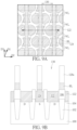
- FIG. 1 A , FIG. 2 A , FIG. 3 A , FIG. 4 A , FIG. 5 A , FIG. 6 A , FIG. 7 A , FIG. 9 A and FIG. 10 A are schematic top views sequentially illustrating the process steps of manufacturing contacts in accordance with one embodiment of the present invention.
- FIG. 1 B , FIG. 2 B , FIG. 3 B , FIG. 4 B , FIG. 5 B , FIG. 6 B , FIG. 7 B , FIG. 8 , FIG. 9 B and FIG. 10 B are schematic cross-sectional views corresponding to the above-mentioned top views in accordance with one embodiment of the present invention.
- etch or “etching” is used herein to generally describe a fabrication process of patterning a material, such that at least a portion of the material remains after the etch is completed.
- the process of etching silicon involves the steps of patterning a photoresist layer above the silicon, and then removing the areas of silicon no longer protected by the photoresist layer. As such, the areas of silicon protected by the photoresist layer would remain behind after the etch process is complete.
- etching may also refer to a process that does not use a photoresist layer, but still leaves behind at least a portion of the material after the etch process is complete.
- etching When etching a material, at least a portion of the material remains behind after the process is completed. In contrast, when removing a material, substantially all of the material is removed in the process. However, in some embodiments, “removing” is considered to be a broad term that may incorporate etching.
- substrate semiconductor substrate
- wafer semiconductor substrate
- term “substrate” or “wafer” may also refer to any semiconductor material such as germanium, gallium arsenide, indium phosphide, and the like.
- the term “substrate” or “wafer” may be non-conductive, such as a glass or sapphire wafer.
- capacitor as used herein refers to a storage node in the architecture of dynamic random access memory (DRAM). It may have different names in other electronic components or memory architecture.
- DRAM dynamic random access memory
- FIGS. 1 A- 10 B are structure diagrams illustrating the process steps of manufacturing contacts of the present invention, wherein each figure is divided into subgraphs A, B (except FIG. 8 ) for demonstrating respectively the schematic top view of said step and the schematic cross-sectional view taken along the section line C-C′ in the schematic top view of said step and clearly showing the connections between parts and layer structures and the layout of semiconductor plane.
- a semiconductor substrate 100 which may include cell regions and peripheral regions of memory. Since the feature of present invention does not relate to the peripheral region of memory, all features shown in the figures are in cell regions rather than in peripheral regions.
- Substrate 100 may be silicon substrate, silicon-on-insulator (SOI) substrate, germanium substrate, germanium-on-insulator (GOI) substrate, silicon-germanium (SiGe) substrate, etc.
- Isolating structures 102 are formed on the substrate 100 by a method of forming trenches first and then filling in the insulating material, such as silicon oxide, silicon nitride, or silicon oxynitride, etc.
- Isolating structure 102 defines the active areas 104 in the cell region on the two-dimensional plane.
- the active areas 104 in two-dimensional plane are in a shape of bar extending in a first direction D 1 and are in staggered arrangement on the substrate surface.
- the active area 104 will be doped beforehand with first type dopants, such as N-type or P-type dopants.
- word lines WL are formed beforehand within the substrate 100 .
- word lines are buried within the substrate in a predetermined depth and pass through the isolating structures 102 and active areas 104 in a second direction D 2 .
- the second direction D 2 is not perpendicular to the first direction D 1 of the active area 104 .
- Word line WL functions as a gate to control the switch of storage units, with the material including but not limited to doped semiconductor material (ex. doped silicon), metal (ex. tungsten, aluminum, titanium or tantalum), conductive metal compound (ex. titanium nitride, tantalum nitride or tungsten nitride) or metal-semiconductor compound (ex. metal silicide), etc.
- doped semiconductor material ex. doped silicon
- metal ex. tungsten, aluminum, titanium or tantalum
- conductive metal compound ex. titanium nitride, tantalum nitride or tungsten nitride
- metal-semiconductor compound ex. metal silicide
- the active areas 104 at two sides of word lines WL may be doped with the second type dopants, such as P-type dopants or N-type dopants, to form source and drain doped regions S/D, wherein the source is at a predetermined position for bit line contact at center of the active area 104 , and the drain is at a predetermined position for storage node contact at the end of active area 104 .
- the word line is not a critical feature of the present invention, relevant process and details will be herein omitted. For the clarity of drawings, word lines WL will be presented by dashed lines.
- section line C-C′ is drawn to cut through the storage node regions and bit line contact regions rather than the word line regions, the structure of word lines will not be shown in the cross-sectional drawings. Only the critical portions of present invention like storage node contacts and bit line contacts will be shown in the drawing.
- an interlayer dielectric (ILD) 106 and a hard mask layer 108 are formed on the substrate 100 , wherein the interlayer dielectric 106 will be used to contain the desired contacts, and the hard mask layer 108 will serve as a mask in later etch processes.
- the interlayer dielectric 106 and hard mask layer 108 will not be shown in FIG. 1 A and other top views.
- mask bars 110 are formed on the hard mask layer 108 .
- mask bar 110 is a part of the etch mask that will be used in later processing, and is disposed in advance to separate the approximate positions of contact at two sides of bit line.
- the position and orientation of mask bars 110 will correspond to the bit lines to be formed in later processing, which extend in a third direction D 3 perpendicular to the second direction D 2 .
- the mask bar is disposed in staggered arrangement between word lines WL and between two ends of adjacent active areas 104 . Said end positions are positions of storage nodes and their contacts, which are exactly spaced apart in pairs by the mask bars.
- the material of mask bar 110 may be silicon oxide and other suitable mask material.
- FIGS. 3 A and 3 B Please refer to FIGS. 3 A and 3 B .
- a mask block 112 is formed on each mask bars 110 .
- the mask block 112 covering the mask bar 110 is an oval shape extending slightly in the second direction D 2 .
- the mask bar 110 is positioned right in the midline of the mask block 112 , with two ends slightly falling outside the scope of mask block 112 .
- the mask block 112 may be formed in other shapes in other embodiments, depending on the layout pattern of active areas 104 .
- the size, shape and coverage of the mask block 112 are designed, so that there will be a predetermined spacing dl defined between adjacent mask blocks 112 , especially the spacing along the first direction D 1 in which the active area extends.
- the purpose of this approach is to form spacers on mask blocks 112 in later processing, and these spacers on adjacent mask blocks 112 should merge together at the position of spacing dl in order to define the desired storage node contact patterns and bit line contact patterns.
- These steps will be explicitly described in the following embodiment.
- the active areas 104 not covered by the mask blocks 112 will be the predetermined positions of bit line contacts.
- the mask block 112 may be defined and formed by multilayers of common organic dielectric layer (ODL), silicon-containing hard mask bottom anti-reflection coating (SHB) and photoresist. Relevant details will be herein omitted.
- a conformal spacer layer 114 is formed on each mask block 112 .
- the material of spacer layer 114 may be the same as the one of mask bar 110 , such as silicon oxide or other suitable mask material.
- the thickness of oval mask block 112 may be precisely controlled by atomic layer deposition.
- the spacer layers 114 would cover entire substrate and merge together at the positions of predetermined spacing dl between adjacent mask block 112 .
- recess patterns 116 are defined between non-merged spacer layers 114 between the mask blocks 112 . These patterns are substantially the bit line contact pattern to be formed in later processing.
- an etch process is then performed to remove the spacer layer 114 on the mask block 112 and the mask blocks 112 itself.
- This etch process may include the following etch steps. First, a first etch process removes the spacer layer 114 of a predetermined thickness so that the mask blocks 112 inside the spacer layer 114 are exposed and the hard mask layer 108 in the recess patterns 116 is also exposed. Then, a second etch process especially and completely removes the mask blocks 112 exposed from the spacer layer 114 . Thus only the spacer layers 114 on sidewalls of each mask block 112 (referred hereinafter as spacer 114 a ) and the mask bars 110 formed in previous process remain on the hard mask layer 108 .
- the spacer 114 a and the mask bar 110 have same material and serve collectively as an etch mask, wherein each mask bar 110 and the spacer 114 a surrounding therearound define two storage node contact patterns 118 , as the semicircular-like patterns shown in the figure.
- Each two storage node contact patterns 118 are separated by a mask bar 110 and correspond to the storage nodes at the ends of active area 104 thereunder, while the bit line contact patterns 120 are defined between spacers 114 a and correspond to the bit line contact portion at the center of active area 104 thereunder.
- FIGS. 6 A and 6 B After the etch masks made up of mask bars 110 and spacers 114 a are formed on the hard mask layer 108 , an etch process is performed using mask bars 110 and spacers 114 a as an etch mask to transfer the storage node contact patterns 118 and the bit line contact patterns 120 defined by the mask bars 110 and spacers 114 a to the hard mask layer 108 thereunder, thereby forming storage node contact recesses 118 a and bit line contact recesses 120 a in the interlayer dielectric 106 .
- FIG. 6 A and 6 B Please note that, as shown in FIG.
- the aforementioned etch steps may remove a portion of the active area 104 and isolating structure 102 , wherein every storage node contact recess 118 a and bit line contact recess 120 a will correspond respectively to the positions of active areas 104 thereunder.
- the pattern corner of is rounded and rendered to a smooth outline, but is limited thereto.
- the storage node contact recess 118 a and the bit line contact recess 120 a are formed by removing interlayer dielectric 106 in the same etch process, the bottoms of two contact recesses will be at the same level.
- the feature like this is different from the feature in prior art that the bit line contact recess is deeper than the storage node contact recess to prevent the connection of the bit line contact and the storage node contact.
- the present invention uses preformed etch masks (i.e.
- the storage node contact 122 and the bit line contact 124 may have a same material, which include but not limited to doped semiconductor material (ex. doped silicon), metal (ex. tungsten, aluminum, titanium or tantalum), conductive metal compound (ex.
- the process of forming these contacts may include forming a conductive layer on the substrate to fill up the storage node contact recesses 118 a and bit line contact recesses 120 a , and a planarization process, such as a chemical mechanical polishing (CMP) process, is then performed to remove the unnecessary conductive material and hard mask layer 108 on the interlayer dielectric 106 , thereby forming the storage node contacts 122 and the bit line contacts 124 with top surfaces flush with surrounding interlayer dielectric 106 as shown in FIG. 7 B .
- CMP chemical mechanical polishing
- the interlayer dielectric 106 and the isolating structure 102 would provide excellent insulation between these contacts to prevent short circuit issue. Please note that conventional bit line contact would go deeper into the substrate than the adjacent storage node contacts rather than have a same bottom level, and these two kinds of contacts would get closer to each other. As mentioned in previous embodiment, this same bottom level feature in the present invention may be attributed to the simultaneous formation of these two different contacts, and the problem of narrow overlay window and short circuit are therefore solved.
- bit lines is started after the storage node contacts 122 and the bit line contacts 124 are formed.
- a metal layer 126 and an insulating layer 128 are subsequently formed on the contacts and the substrate.
- the metal layer 126 is used to form bit lines, with the material of tungsten, aluminum, titanium, or tantalum, etc.
- the insulating layer 128 is a thicker layer, with the material of silicon nitride, silicon oxide, or silicon oxynitride, etc.
- the insulating layer 128 may serve as a molding structure to define the size and length of contact plug to be formed in later processing and provide insulating efficacy therebetween.
- bit line BL extends in the third direction D 3 and perpendicularly intersects the word line WL formed in a previous process.
- the bit line BL would extend right above the bit line contacts 124 and through the active area 104 between two storage node contacts 122 .
- bit line BL would electrically connect with the bit line contact 124 rather than the adjacent storage node contacts 122 .
- the insulating layer 128 a right above the bit line BL is not shown in FIG. 9 A .
- the insulating layer 128 a may also serve as a molding layer to define recesses between bit lines with predetermined depth. These recesses will be used to contain desired contact plugs to be formed in later process. Please note that the aforementioned etch process would remove a portion of the storage node contact 122 and bit line contact 124 , so that their top surface would be slightly lower than the surrounding interlayer dielectric 106 . This approach may help to prevent the short circuit between the bit line contact 124 and the contact plug to be formed in later process.
- FIGS. 10 A and 10 B The formation of contact plugs adjacent to the bit lines BL is started after the bit lines BL are formed.
- an insulating spacer layer 132 is first formed on sidewalls of bit lines BL and the insulating layer 128 a .
- the spacer layer 132 would also cover the interlayer dielectric 106 at two sides of the bit line contacts 124 and fill into the recesses therebetween to achieve the insulating efficacy.
- the material of spacer layer 132 may include but not limited to silicon nitride, silicon oxide, or silicon oxynitride, etc. Alternatively, it may be a multilayer structure.
- the contact plugs are formed in the recesses 130 between the spacer layers 132 .
- Each contact plug would electrically connect with the storage node contact 122 thereunder, with the spacer layer 132 and interlayer dielectric 106 to provide isolation against the bit lines BL and bit line contacts 124 .
- a molding layer is necessary in the second direction D 2 to confine the position of every contact plug collectively with the insulating layer 128 a in the first direction D 1 .
- the relevant process may include filling a sacrificial layer into the recesses 130 , and then defining and forming the molding layer on the word line WL in the sacrificial layer.
- the molding layer has same orientation as the word line WL and may have a same material as the one of insulating layer 128 a .
- the sacrificial layer is then removed and the defined plug spaces or plug holes are filled with plug material, thereby forming the contact plugs 134 as shown in FIG. 10 A .
- the contact plug 134 may be formed by using other different processes, and it may further electrically connect to the capacitor pad and storage capacitor (not shown) to be formed thereon. Since relevant processes for manufacturing the contact plugs 134 and their interconnections are all conventional skills and are not the critical features of present invention, those descriptions will be herein omitted to prevent the obscuring of the present invention.
- contact plugs 134 and corresponding storage node contacts 122 are shown in the figures. So far, the upper contact plug 134 and the lower storage node contact (may also referred as contact pad) 122 may be considered as a complete contact structure of the storage node.
Abstract
A method of manufacturing contacts is provided in the present invention, which include the steps of forming a plurality of mask bars on a substrate, forming a circular mask surrounding each mask bar, wherein the circular masks connect each other and define a plurality of opening patterns collectively with the mask bars, using the mask bars and the circular masks as etch masks to perform an etch process and to transfer the opening patterns and form a plurality recesses in the substrate, and filling up the recesses with metal to form contacts.
Description
This application is a divisional of application Ser. No. 16/011,652, filed on Jun. 19, 2018 and entitled “CONTACTS AND METHOD OF MANUFACTURING THE SAME”, which is incorporated herein by reference.
The present invention relates generally to contacts and method of manufacturing the same, and more specifically, to bit line contacts and storage node contacts in dynamic random access memory (DRAM) and method of manufacturing the same.
As electronic products develop toward the direction of miniaturization, the design of dynamic random access memory (DRAM) units also moves toward the direction of higher integration and higher density. Since the nature of a DRAM unit with buried gate structures has the advantage of possessing longer carrier channel length within a semiconductor substrate thereby reducing capacitor leakage, it has been gradually used to replace conventional DRAM unit with planar gate structures.
Typically, a DRAM unit with buried gate structure includes a transistor device and a charge storage element to receive electrical signals from bit lines and word lines. The capacitor in DRAM electrically connects with a capacitor landing pad through its bottom electrode, and further electrically connects to the drain of transistor through a storage node contact and a contact pad. Bit lines and word lines are buried within the substrate, wherein bit line is electrically connected to the source of transistor through a bit line contact, while word line serves as a gate for storage units.
With the rapid increase in the degree of integration on the DRAM, the size of the capacitor landing pad is also smaller. However, due to the bottleneck of the process technology, an unexpected misalignment situation often occurs at the exposure step used to define the location of the capacitor landing pad. The error margin is very small, resulting in the subsequent short circuit between the capacitor landing pads and the bit lines when the capacitor landing pads are formed. Furthermore, for current recessed DRAM structure, the bit line contact would go deeper than surrounding components (ex. storage node contact). In order to achieve this depth, the time period of corresponding etch process would be longer than normal etch process. This approach is prone to damage sensitive layer structures, such as the gate dielectric layer already formed in the peripheral region.
Therefore, there still exist many defects in the manufacturing process of the DRAM cell with the buried gate structure, and the efficiency and reliability of the related memory device need to be further improved.
In order to solve the problems prone to happen in DRAM process as described above, novel contacts and a method of manufacturing the same are provided in the present invention, which features the bit line contacts and storage node contacts defined and formed by self-alignment method to prevent short-circuit issue in prior art caused from the electrical connection of bit line contacts and storage node contacts formed thereafter. In addition, since the two kinds of contacts are simultaneously formed, the bit line contact and the storage node contact would have the same depth so that long-period etch process is not necessary to ensure that layer structures in peripheral region would not suffer damage.
One aspect of the present invention is to provide a method of manufacturing contacts, which includes the steps of providing multiple mask bars on a substrate, forming a circular mask around each mask bar, wherein the circular masks connect with each other and define multiple opening patterns collectively with the mask bars, performing an etch process using the mask bars and the circular masks as etch masks to transfer the opening patterns to the substrate and to form multiple recesses in the substrate, and filling every recess with metal to form contacts connecting with active areas in the substrate.
Another aspect of the present invention is to a provide contact including a substrate with multiple active areas isolated by shallow trench isolations, multiple bit line contacts in the substrate and connecting with the active areas, and multiple storage node contacts in the substrate and connecting with the active areas and the shallow trench isolations, wherein storage node contacts are provided at two sides of each bit line contact, and the bottom of storage node contact is level with the bottom of bit line contact.
These and other objectives of the present invention will no doubt become obvious to those of ordinary skill in the art after reading the following detailed description of the preferred embodiment that is illustrated in the various figures and drawings.
The accompanying drawings are included to provide a further understanding of the embodiments, and are incorporated in and constitute apart of this specification. The drawings illustrate some of the embodiments and, together with the description, serve to explain their principles. In the drawings:
It should be noted that all the figures are diagrammatic. Relative dimensions and proportions of parts of the drawings have been shown exaggerated or reduced in size, for the sake of clarity and convenience in the drawings. The same reference signs are generally used to refer to corresponding or similar features in modified and different embodiments.
In the following detailed description, reference is made to the accompanying drawings which form a part hereof, and in which is shown by way of illustration specific embodiments in which the invention may be practiced. These embodiments are described in sufficient detail to enable those skilled in the art to practice the invention. In the drawings, the size and relative sizes of components and regions may be exaggerated for clarity unless express so defined herein. It is to be understood that other embodiments may be utilized and that structural, logical and electrical changes may be made without departing from the spirit and scope of the present invention. The following detailed description is, therefore, not to be taken in a limiting sense, and the scope of the present invention is defined by the appended claims.
Before describing the preferred embodiment, the following description will be given for specific terms used throughout the specification. The term “etch” or “etching” is used herein to generally describe a fabrication process of patterning a material, such that at least a portion of the material remains after the etch is completed. For example, it should be understood that the process of etching silicon involves the steps of patterning a photoresist layer above the silicon, and then removing the areas of silicon no longer protected by the photoresist layer. As such, the areas of silicon protected by the photoresist layer would remain behind after the etch process is complete. However, in another example, etching may also refer to a process that does not use a photoresist layer, but still leaves behind at least a portion of the material after the etch process is complete.
The above description serves to distinguish the term “etching” from “removing.” When etching a material, at least a portion of the material remains behind after the process is completed. In contrast, when removing a material, substantially all of the material is removed in the process. However, in some embodiments, “removing” is considered to be a broad term that may incorporate etching.
The term “substrate,” “semiconductor substrate” or “wafer” as described throughout, is most commonly a silicon substrate or a silicon wafer. However, term “substrate” or “wafer” may also refer to any semiconductor material such as germanium, gallium arsenide, indium phosphide, and the like. In other embodiments, the term “substrate” or “wafer” may be non-conductive, such as a glass or sapphire wafer. In addition, the term “capacitor” as used herein refers to a storage node in the architecture of dynamic random access memory (DRAM). It may have different names in other electronic components or memory architecture.
In the drawing of present invention, FIGS. 1A-10B are structure diagrams illustrating the process steps of manufacturing contacts of the present invention, wherein each figure is divided into subgraphs A, B (except FIG. 8 ) for demonstrating respectively the schematic top view of said step and the schematic cross-sectional view taken along the section line C-C′ in the schematic top view of said step and clearly showing the connections between parts and layer structures and the layout of semiconductor plane.
Please refer to FIGS. 1A and 1B . First, prepare a semiconductor substrate 100 which may include cell regions and peripheral regions of memory. Since the feature of present invention does not relate to the peripheral region of memory, all features shown in the figures are in cell regions rather than in peripheral regions. Substrate 100 may be silicon substrate, silicon-on-insulator (SOI) substrate, germanium substrate, germanium-on-insulator (GOI) substrate, silicon-germanium (SiGe) substrate, etc. Isolating structures 102 are formed on the substrate 100 by a method of forming trenches first and then filling in the insulating material, such as silicon oxide, silicon nitride, or silicon oxynitride, etc. Isolating structure 102 defines the active areas 104 in the cell region on the two-dimensional plane.
In the embodiment of present invention, as shown in FIG. 1A , the active areas 104 in two-dimensional plane are in a shape of bar extending in a first direction D1 and are in staggered arrangement on the substrate surface. The active area 104 will be doped beforehand with first type dopants, such as N-type or P-type dopants. In the embodiment, word lines WL are formed beforehand within the substrate 100. In the architecture of recessed gate, word lines are buried within the substrate in a predetermined depth and pass through the isolating structures 102 and active areas 104 in a second direction D2. The second direction D2 is not perpendicular to the first direction D1 of the active area 104. Word line WL functions as a gate to control the switch of storage units, with the material including but not limited to doped semiconductor material (ex. doped silicon), metal (ex. tungsten, aluminum, titanium or tantalum), conductive metal compound (ex. titanium nitride, tantalum nitride or tungsten nitride) or metal-semiconductor compound (ex. metal silicide), etc.
Furthermore, the active areas 104 at two sides of word lines WL may be doped with the second type dopants, such as P-type dopants or N-type dopants, to form source and drain doped regions S/D, wherein the source is at a predetermined position for bit line contact at center of the active area 104, and the drain is at a predetermined position for storage node contact at the end of active area 104. Since the word line is not a critical feature of the present invention, relevant process and details will be herein omitted. For the clarity of drawings, word lines WL will be presented by dashed lines. In addition, since the section line C-C′ is drawn to cut through the storage node regions and bit line contact regions rather than the word line regions, the structure of word lines will not be shown in the cross-sectional drawings. Only the critical portions of present invention like storage node contacts and bit line contacts will be shown in the drawing.
As shown in FIG. 1B , an interlayer dielectric (ILD) 106 and a hard mask layer 108, such as a silicon nitride layer and an amorphous layer, are formed on the substrate 100, wherein the interlayer dielectric 106 will be used to contain the desired contacts, and the hard mask layer 108 will serve as a mask in later etch processes. Please note that, in order to clearly present the layout pattern of every portion, the interlayer dielectric 106 and hard mask layer 108 will not be shown in FIG. 1A and other top views.
As shown in FIGS. 2A and 2B , after the active areas 104 are defined and the interlayer dielectric 106 and hard mask layer 108 are formed, mask bars 110 are formed on the hard mask layer 108. In the embodiment of the present invention, mask bar 110 is a part of the etch mask that will be used in later processing, and is disposed in advance to separate the approximate positions of contact at two sides of bit line. The position and orientation of mask bars 110 will correspond to the bit lines to be formed in later processing, which extend in a third direction D3 perpendicular to the second direction D2. More specifically, as shown in FIG. 2A , the mask bar is disposed in staggered arrangement between word lines WL and between two ends of adjacent active areas 104. Said end positions are positions of storage nodes and their contacts, which are exactly spaced apart in pairs by the mask bars. The material of mask bar 110 may be silicon oxide and other suitable mask material.
Please refer to FIGS. 3A and 3B . After the mask bars 110 are formed on hard mask layer 108, a mask block 112 is formed on each mask bars 110. As shown in FIG. 3A , the mask block 112 covering the mask bar 110 is an oval shape extending slightly in the second direction D2. The mask bar 110 is positioned right in the midline of the mask block 112, with two ends slightly falling outside the scope of mask block 112. Please note that the mask block 112 may be formed in other shapes in other embodiments, depending on the layout pattern of active areas 104. In the embodiment of the present invention, the size, shape and coverage of the mask block 112 are designed, so that there will be a predetermined spacing dl defined between adjacent mask blocks 112, especially the spacing along the first direction D1 in which the active area extends. The purpose of this approach is to form spacers on mask blocks 112 in later processing, and these spacers on adjacent mask blocks 112 should merge together at the position of spacing dl in order to define the desired storage node contact patterns and bit line contact patterns. These steps will be explicitly described in the following embodiment. In this stage, the active areas 104 not covered by the mask blocks 112 will be the predetermined positions of bit line contacts. The mask block 112 may be defined and formed by multilayers of common organic dielectric layer (ODL), silicon-containing hard mask bottom anti-reflection coating (SHB) and photoresist. Relevant details will be herein omitted.
Please refer to FIGS. 4A and 4B . After the mask blocks 112 are formed on the mask bars 110, a conformal spacer layer 114 is formed on each mask block 112. The material of spacer layer 114 may be the same as the one of mask bar 110, such as silicon oxide or other suitable mask material. The thickness of oval mask block 112 may be precisely controlled by atomic layer deposition. As mentioned above, the spacer layers 114 would cover entire substrate and merge together at the positions of predetermined spacing dl between adjacent mask block 112. In this way, as shown in FIGS. 4A and 4B , recess patterns 116 are defined between non-merged spacer layers 114 between the mask blocks 112. These patterns are substantially the bit line contact pattern to be formed in later processing.
Please refer to FIGS. 5A and 5B . After the conformal spacer layer 114 is formed on the mask blocks 112, an etch process is then performed to remove the spacer layer 114 on the mask block 112 and the mask blocks 112 itself. This etch process may include the following etch steps. First, a first etch process removes the spacer layer 114 of a predetermined thickness so that the mask blocks 112 inside the spacer layer 114 are exposed and the hard mask layer 108 in the recess patterns 116 is also exposed. Then, a second etch process especially and completely removes the mask blocks 112 exposed from the spacer layer 114. Thus only the spacer layers 114 on sidewalls of each mask block 112 (referred hereinafter as spacer 114 a) and the mask bars 110 formed in previous process remain on the hard mask layer 108.
In the embodiment of the present invention, the spacer 114 a and the mask bar 110 have same material and serve collectively as an etch mask, wherein each mask bar 110 and the spacer 114 a surrounding therearound define two storage node contact patterns 118, as the semicircular-like patterns shown in the figure. Each two storage node contact patterns 118 are separated by a mask bar 110 and correspond to the storage nodes at the ends of active area 104 thereunder, while the bit line contact patterns 120 are defined between spacers 114 a and correspond to the bit line contact portion at the center of active area 104 thereunder.
Please refer to FIGS. 6A and 6B . After the etch masks made up of mask bars 110 and spacers 114 a are formed on the hard mask layer 108, an etch process is performed using mask bars 110 and spacers 114 a as an etch mask to transfer the storage node contact patterns 118 and the bit line contact patterns 120 defined by the mask bars 110 and spacers 114 a to the hard mask layer 108 thereunder, thereby forming storage node contact recesses 118 a and bit line contact recesses 120 a in the interlayer dielectric 106. Please note that, as shown in FIG. 6B , the aforementioned etch steps may remove a portion of the active area 104 and isolating structure 102, wherein every storage node contact recess 118 a and bit line contact recess 120 a will correspond respectively to the positions of active areas 104 thereunder. As shown in FIG. 6A , after the storage node contact pattern 118 and the bit line contact pattern 120 are transferred to form the storage node contact recess 118 a and the bit line contact recess 120 a, the pattern corner of is rounded and rendered to a smooth outline, but is limited thereto.
In the embodiment of the present invention, since the storage node contact recess 118 a and the bit line contact recess 120 a are formed by removing interlayer dielectric 106 in the same etch process, the bottoms of two contact recesses will be at the same level. The feature like this is different from the feature in prior art that the bit line contact recess is deeper than the storage node contact recess to prevent the connection of the bit line contact and the storage node contact. Furthermore, since the present invention uses preformed etch masks (i.e. mask bars 110 and spacers 114 a) in the etch process to simultaneously form the storage node contact recesses 118 a and the bit line contact recesses 120 a, the issue of overlay shift caused by different recess processes in prior art will not occur, and the problems of low overlay window and short circuit due to small spacing between bit line contact and storage node contact in current high-integrity circuit design may be successfully solved.
Please refer to FIGS. 7A and 7B . After the storage node contact recesses 118 a and the bit line contact recesses 120 a are formed in the interlayer dielectric 106, conductive material is then filled into the storage node contact recesses 118 a and the bit line contact recesses 120 a to form storage node contacts 122 and bit line contacts 124 respectively, and which further connect respectively to drain doped region D and source doped region S preformed thereunder. In the embodiment of the present invention, the storage node contact 122 and the bit line contact 124 may have a same material, which include but not limited to doped semiconductor material (ex. doped silicon), metal (ex. tungsten, aluminum, titanium or tantalum), conductive metal compound (ex. titanium nitride, tantalum nitride or tungsten nitride) or metal-semiconductor compound (ex. metal silicide), etc. The process of forming these contacts may include forming a conductive layer on the substrate to fill up the storage node contact recesses 118 a and bit line contact recesses 120 a, and a planarization process, such as a chemical mechanical polishing (CMP) process, is then performed to remove the unnecessary conductive material and hard mask layer 108 on the interlayer dielectric 106, thereby forming the storage node contacts 122 and the bit line contacts 124 with top surfaces flush with surrounding interlayer dielectric 106 as shown in FIG. 7B .
The interlayer dielectric 106 and the isolating structure 102 would provide excellent insulation between these contacts to prevent short circuit issue. Please note that conventional bit line contact would go deeper into the substrate than the adjacent storage node contacts rather than have a same bottom level, and these two kinds of contacts would get closer to each other. As mentioned in previous embodiment, this same bottom level feature in the present invention may be attributed to the simultaneous formation of these two different contacts, and the problem of narrow overlay window and short circuit are therefore solved.
Please refer to FIG. 8 . The formation of bit lines is started after the storage node contacts 122 and the bit line contacts 124 are formed. First, a metal layer 126 and an insulating layer 128 are subsequently formed on the contacts and the substrate. The metal layer 126 is used to form bit lines, with the material of tungsten, aluminum, titanium, or tantalum, etc. The insulating layer 128 is a thicker layer, with the material of silicon nitride, silicon oxide, or silicon oxynitride, etc. The insulating layer 128 may serve as a molding structure to define the size and length of contact plug to be formed in later processing and provide insulating efficacy therebetween.
Please refer to FIGS. 9A and 9B . After the metal layer 126 and the insulating layer 128 are formed on the contacts, a photolithographic and etch process is performed to pattern the metal layer 126 and the insulating layer 128 into bit lines BL. As shown in FIG. 9A , bit line BL extends in the third direction D3 and perpendicularly intersects the word line WL formed in a previous process. The bit line BL would extend right above the bit line contacts 124 and through the active area 104 between two storage node contacts 122. Thus, bit line BL would electrically connect with the bit line contact 124 rather than the adjacent storage node contacts 122. Please note for the clarity of description, the insulating layer 128 a right above the bit line BL is not shown in FIG. 9A .
On the other hand, as shown in FIG. 9B , the insulating layer 128 a may also serve as a molding layer to define recesses between bit lines with predetermined depth. These recesses will be used to contain desired contact plugs to be formed in later process. Please note that the aforementioned etch process would remove a portion of the storage node contact 122 and bit line contact 124, so that their top surface would be slightly lower than the surrounding interlayer dielectric 106. This approach may help to prevent the short circuit between the bit line contact 124 and the contact plug to be formed in later process.
Please refer to FIGS. 10A and 10B . The formation of contact plugs adjacent to the bit lines BL is started after the bit lines BL are formed. First, in order to isolate the bit lines BL and adjacent contact plugs to be formed in this process, an insulating spacer layer 132 is first formed on sidewalls of bit lines BL and the insulating layer 128 a. As shown in FIG. 10B , in addition to bit lines BL and insulating layer 128 a, the spacer layer 132 would also cover the interlayer dielectric 106 at two sides of the bit line contacts 124 and fill into the recesses therebetween to achieve the insulating efficacy. The material of spacer layer 132 may include but not limited to silicon nitride, silicon oxide, or silicon oxynitride, etc. Alternatively, it may be a multilayer structure.
After the spacer layer 132 is formed, the contact plugs are formed in the recesses 130 between the spacer layers 132. Each contact plug would electrically connect with the storage node contact 122 thereunder, with the spacer layer 132 and interlayer dielectric 106 to provide isolation against the bit lines BL and bit line contacts 124. Subsequently, in order to define the pattern of contact plug, a molding layer is necessary in the second direction D2 to confine the position of every contact plug collectively with the insulating layer 128 a in the first direction D1. The relevant process may include filling a sacrificial layer into the recesses 130, and then defining and forming the molding layer on the word line WL in the sacrificial layer. The molding layer has same orientation as the word line WL and may have a same material as the one of insulating layer 128 a. The sacrificial layer is then removed and the defined plug spaces or plug holes are filled with plug material, thereby forming the contact plugs 134 as shown in FIG. 10A . Please note that the contact plug 134 may be formed by using other different processes, and it may further electrically connect to the capacitor pad and storage capacitor (not shown) to be formed thereon. Since relevant processes for manufacturing the contact plugs 134 and their interconnections are all conventional skills and are not the critical features of present invention, those descriptions will be herein omitted to prevent the obscuring of the present invention. To simplify the drawings, only the layout and cross-sections of contact plugs 134 and corresponding storage node contacts 122 are shown in the figures. So far, the upper contact plug 134 and the lower storage node contact (may also referred as contact pad) 122 may be considered as a complete contact structure of the storage node.
Those skilled in the art will readily observe that numerous modifications and alterations of the device and method may be made while retaining the teachings of the invention. Accordingly, the above disclosure should be construed as limited only by the metes and bounds of the appended claims.
Claims (8)
1. A method of manufacturing contacts, comprising:
providing a substrate, wherein said substrate has a plurality of active areas;
forming a plurality of mask bars on said substrate;
forming a spacer around each of said mask bars, comprising:
forming a mask block on said each of said mask bars, wherein said mask bar is in the midline of said mask block;
forming a conformal spacer layer on said substrate and said mask blocks, wherein said spacer layer on said mask blocks connects with each other to define a plurality of first opening patterns; and
performing a first etch process to etch said spacer layer and said mask blocks so that said spacer layer on said mask blocks is removed and said spacer layer on sidewalls of said mask blocks remains to form a plurality of said spacers, wherein said mask blocks are completely removed and each of said spacers and said each of said mask bars define two second opening patterns;
performing an etch process using said plurality of mask bars and said plurality of said spacers as etch masks to transfer said first opening patterns and said second opening patterns to said substrate and to form a plurality of recesses in said substrate; and
filling each of said recesses with conductive material to form contacts, wherein said contacts connect with said plurality of active areas.
2. The method of manufacturing contacts of claim 1 , wherein said first opening patterns define bit line contact patterns, and said second opening patterns define storage node contact patterns.
3. The method of manufacturing contacts of claim 1 , wherein each said first opening patterns is on the center of one said active area, and every two said second opening patterns are on two opposite ends of one said active area.
4. The method of manufacturing contacts of claim 1 , wherein said etch process transfers said first opening patterns and said second opening patterns to said substrate to form a plurality of first recesses and a plurality of second recesses respectively in said substrate.
5. The method of manufacturing contacts of claim 4 , wherein said contact in said first recess is bit line contact, said contact in said second recess is storage node contact.
6. The method of manufacturing contacts of claim 5 , further comprising forming bit lines on said bit line contacts to connect with said bit lines, wherein said bit line and said plurality of mask bars overlap.
7. The method of manufacturing contacts of claim 5 , further comprising forming contact plug on every said storage node contacts.
8. The method of manufacturing contacts of claim 1 , wherein said plurality of mask bars form in staggered arrangement between word lines and between two adjacent ends of said active areas.
Priority Applications (1)
| Application Number | Priority Date | Filing Date | Title |
|---|---|---|---|
| US17/235,950 US11653491B2 (en) | 2017-08-08 | 2021-04-21 | Contacts and method of manufacturing the same |
Applications Claiming Priority (4)
| Application Number | Priority Date | Filing Date | Title |
|---|---|---|---|
| CN201710669727.2 | 2017-08-08 | ||
| CN201710669727.2A CN109390285B (en) | 2017-08-08 | 2017-08-08 | Contact structure and manufacturing method thereof |
| US16/011,652 US11018141B2 (en) | 2017-08-08 | 2018-06-19 | Contacts and method of manufacturing the same |
| US17/235,950 US11653491B2 (en) | 2017-08-08 | 2021-04-21 | Contacts and method of manufacturing the same |
Related Parent Applications (1)
| Application Number | Title | Priority Date | Filing Date |
|---|---|---|---|
| US16/011,652 Division US11018141B2 (en) | 2017-08-08 | 2018-06-19 | Contacts and method of manufacturing the same |
Publications (2)
| Publication Number | Publication Date |
|---|---|
| US20210242214A1 US20210242214A1 (en) | 2021-08-05 |
| US11653491B2 true US11653491B2 (en) | 2023-05-16 |
Family
ID=65274325
Family Applications (2)
| Application Number | Title | Priority Date | Filing Date |
|---|---|---|---|
| US16/011,652 Active US11018141B2 (en) | 2017-08-08 | 2018-06-19 | Contacts and method of manufacturing the same |
| US17/235,950 Active US11653491B2 (en) | 2017-08-08 | 2021-04-21 | Contacts and method of manufacturing the same |
Family Applications Before (1)
| Application Number | Title | Priority Date | Filing Date |
|---|---|---|---|
| US16/011,652 Active US11018141B2 (en) | 2017-08-08 | 2018-06-19 | Contacts and method of manufacturing the same |
Country Status (2)
| Country | Link |
|---|---|
| US (2) | US11018141B2 (en) |
| CN (1) | CN109390285B (en) |
Families Citing this family (7)
| Publication number | Priority date | Publication date | Assignee | Title |
|---|---|---|---|---|
| CN112447604B (en) * | 2019-08-30 | 2022-06-10 | 长鑫存储技术有限公司 | Memory and forming method thereof |
| CN111653563B (en) * | 2020-05-28 | 2022-03-04 | 福建省晋华集成电路有限公司 | Layout structure of dynamic random access memory and manufacturing method of photomask |
| CN113097146B (en) * | 2021-03-31 | 2022-06-17 | 长鑫存储技术有限公司 | Preparation method of semiconductor structure and semiconductor structure |
| CN113471148B (en) * | 2021-07-01 | 2022-07-22 | 长鑫存储技术有限公司 | Method for manufacturing semiconductor structure |
| CN116133374A (en) * | 2021-08-20 | 2023-05-16 | 长鑫存储技术有限公司 | Semiconductor structure and mask structure |
| CN114093820A (en) * | 2021-11-01 | 2022-02-25 | 长鑫存储技术有限公司 | Preparation method of active region structure, semiconductor structure and semiconductor memory |
| US11903186B2 (en) * | 2022-04-21 | 2024-02-13 | Nanya Technology Corporation | Method for manufacturing semiconductor device with bit line contacts of different pitches |
Citations (12)
| Publication number | Priority date | Publication date | Assignee | Title |
|---|---|---|---|---|
| US6551877B1 (en) | 2002-06-11 | 2003-04-22 | Powerchip Semiconductor Corp. | Method of manufacturing memory device |
| CN101154031A (en) | 2006-09-29 | 2008-04-02 | 海力士半导体有限公司 | Method of forming hardmask pattern of semiconductor device |
| CN101315903A (en) | 2007-06-01 | 2008-12-03 | 株式会社东芝 | Semiconductor device manufacturing method |
| US20090098732A1 (en) * | 2007-10-10 | 2009-04-16 | Hynix Semiconductor Inc. | Semiconductor device and method of forming contact plug of semiconductor device |
| US20110183505A1 (en) * | 2010-01-28 | 2011-07-28 | Samsung Electronics Co., Ltd. | Methods of forming fine patterns in integrated circuit devices and methods of manufacturing integrated circuit devices including the same |
| KR20120004109A (en) | 2010-07-06 | 2012-01-12 | 주식회사 하이닉스반도체 | Method for fabricating contact hole in semiconductor device |
| US20120187535A1 (en) | 2011-01-26 | 2012-07-26 | Hynix Semiconductor Inc. | Semiconductor device and method for manufacturing the same |
| US20130154101A1 (en) | 2011-12-16 | 2013-06-20 | SK Hynix Inc. | Semiconductor device and method for manufacturing the same |
| US20130171818A1 (en) | 2011-12-29 | 2013-07-04 | Samsung Electronics Co., Ltd. | Method of Manufacturing A Semiconductor Device |
| US20140134812A1 (en) | 2012-11-13 | 2014-05-15 | Dong-chan Kim | Method of fabricating semiconductor device |
| US20160181258A1 (en) | 2014-12-22 | 2016-06-23 | Samsung Electronics Co., Ltd. | Methods of Fabricating Semiconductor Devices |
| US9627387B2 (en) | 2014-12-04 | 2017-04-18 | Samsung Electronics Co., Ltd. | Semiconductor device and method for manufacturing the same |
-
2017
- 2017-08-08 CN CN201710669727.2A patent/CN109390285B/en active Active
-
2018
- 2018-06-19 US US16/011,652 patent/US11018141B2/en active Active
-
2021
- 2021-04-21 US US17/235,950 patent/US11653491B2/en active Active
Patent Citations (12)
| Publication number | Priority date | Publication date | Assignee | Title |
|---|---|---|---|---|
| US6551877B1 (en) | 2002-06-11 | 2003-04-22 | Powerchip Semiconductor Corp. | Method of manufacturing memory device |
| CN101154031A (en) | 2006-09-29 | 2008-04-02 | 海力士半导体有限公司 | Method of forming hardmask pattern of semiconductor device |
| CN101315903A (en) | 2007-06-01 | 2008-12-03 | 株式会社东芝 | Semiconductor device manufacturing method |
| US20090098732A1 (en) * | 2007-10-10 | 2009-04-16 | Hynix Semiconductor Inc. | Semiconductor device and method of forming contact plug of semiconductor device |
| US20110183505A1 (en) * | 2010-01-28 | 2011-07-28 | Samsung Electronics Co., Ltd. | Methods of forming fine patterns in integrated circuit devices and methods of manufacturing integrated circuit devices including the same |
| KR20120004109A (en) | 2010-07-06 | 2012-01-12 | 주식회사 하이닉스반도체 | Method for fabricating contact hole in semiconductor device |
| US20120187535A1 (en) | 2011-01-26 | 2012-07-26 | Hynix Semiconductor Inc. | Semiconductor device and method for manufacturing the same |
| US20130154101A1 (en) | 2011-12-16 | 2013-06-20 | SK Hynix Inc. | Semiconductor device and method for manufacturing the same |
| US20130171818A1 (en) | 2011-12-29 | 2013-07-04 | Samsung Electronics Co., Ltd. | Method of Manufacturing A Semiconductor Device |
| US20140134812A1 (en) | 2012-11-13 | 2014-05-15 | Dong-chan Kim | Method of fabricating semiconductor device |
| US9627387B2 (en) | 2014-12-04 | 2017-04-18 | Samsung Electronics Co., Ltd. | Semiconductor device and method for manufacturing the same |
| US20160181258A1 (en) | 2014-12-22 | 2016-06-23 | Samsung Electronics Co., Ltd. | Methods of Fabricating Semiconductor Devices |
Also Published As
| Publication number | Publication date |
|---|---|
| CN109390285B (en) | 2021-02-12 |
| US11018141B2 (en) | 2021-05-25 |
| US20190051654A1 (en) | 2019-02-14 |
| US20210242214A1 (en) | 2021-08-05 |
| CN109390285A (en) | 2019-02-26 |
Similar Documents
| Publication | Publication Date | Title |
|---|---|---|
| US11653491B2 (en) | Contacts and method of manufacturing the same | |
| US10593677B2 (en) | Semiconductor structure with capacitor landing pad and method of make the same | |
| US9613967B1 (en) | Memory device and method of fabricating the same | |
| KR101116359B1 (en) | Semiconductor device with buried gate and method for manufacturing | |
| US10439048B2 (en) | Photomask layout, methods of forming fine patterns and method of manufacturing semiconductor devices | |
| US20130196477A1 (en) | Methods of fabricating a semiconductor device including fine patterns | |
| CN110223982B (en) | Dynamic random access memory and manufacturing method thereof | |
| US10475794B1 (en) | Semiconductor device and method for fabricating the same | |
| US11244948B2 (en) | Semiconductor device and method of forming the same | |
| CN111799261B (en) | Semiconductor structure with capacitor connection pad and manufacturing method of capacitor connection pad | |
| US10658365B2 (en) | Semiconductor device and method of manufacturing the same | |
| KR20150096183A (en) | Semiconductor device and method of the same | |
| US20120187535A1 (en) | Semiconductor device and method for manufacturing the same | |
| US10147728B1 (en) | Semiconductor device and method for fabricating the same | |
| KR101095787B1 (en) | Semiconductor device and method of fabricating the same | |
| KR20120128518A (en) | Method for manufacturing the semiconductor device | |
| US11665888B2 (en) | Semiconductor device and method for fabricating the same | |
| KR20110001136A (en) | Method for manufacturing semiconductor device | |
| KR101213728B1 (en) | Method for forming semiconductor device | |
| US11121136B2 (en) | Insulating structure and method of forming the same | |
| US20240064960A1 (en) | Semiconductor memory device and method of fabricating the same | |
| KR100293715B1 (en) | Manufacturing method of highly integrated semiconductor memory device | |
| KR20100135520A (en) | Semiconductor device and method for manufacturing the same |
Legal Events
| Date | Code | Title | Description |
|---|---|---|---|
| FEPP | Fee payment procedure |
Free format text: ENTITY STATUS SET TO UNDISCOUNTED (ORIGINAL EVENT CODE: BIG.); ENTITY STATUS OF PATENT OWNER: LARGE ENTITY |
|
| STPP | Information on status: patent application and granting procedure in general |
Free format text: APPLICATION DISPATCHED FROM PREEXAM, NOT YET DOCKETED |
|
| STPP | Information on status: patent application and granting procedure in general |
Free format text: DOCKETED NEW CASE - READY FOR EXAMINATION |
|
| STPP | Information on status: patent application and granting procedure in general |
Free format text: NON FINAL ACTION MAILED |
|
| STCF | Information on status: patent grant |
Free format text: PATENTED CASE |