US11648604B2 - Robot vision-based automatic rivet placement system and method - Google Patents
Robot vision-based automatic rivet placement system and method Download PDFInfo
- Publication number
- US11648604B2 US11648604B2 US17/289,020 US201917289020A US11648604B2 US 11648604 B2 US11648604 B2 US 11648604B2 US 201917289020 A US201917289020 A US 201917289020A US 11648604 B2 US11648604 B2 US 11648604B2
- Authority
- US
- United States
- Prior art keywords
- rivet
- support frame
- cover plate
- rivets
- placement system
- Prior art date
- Legal status (The legal status is an assumption and is not a legal conclusion. Google has not performed a legal analysis and makes no representation as to the accuracy of the status listed.)
- Active
Links
Images


Classifications
-
- B—PERFORMING OPERATIONS; TRANSPORTING
- B21—MECHANICAL METAL-WORKING WITHOUT ESSENTIALLY REMOVING MATERIAL; PUNCHING METAL
- B21J—FORGING; HAMMERING; PRESSING METAL; RIVETING; FORGE FURNACES
- B21J15/00—Riveting
- B21J15/10—Riveting machines
- B21J15/14—Riveting machines specially adapted for riveting specific articles, e.g. brake lining machines
- B21J15/142—Aerospace structures
-
- B—PERFORMING OPERATIONS; TRANSPORTING
- B21—MECHANICAL METAL-WORKING WITHOUT ESSENTIALLY REMOVING MATERIAL; PUNCHING METAL
- B21J—FORGING; HAMMERING; PRESSING METAL; RIVETING; FORGE FURNACES
- B21J15/00—Riveting
- B21J15/10—Riveting machines
- B21J15/16—Drives for riveting machines; Transmission means therefor
- B21J15/26—Drives for riveting machines; Transmission means therefor operated by rotary drive, e.g. by electric motor
-
- B—PERFORMING OPERATIONS; TRANSPORTING
- B21—MECHANICAL METAL-WORKING WITHOUT ESSENTIALLY REMOVING MATERIAL; PUNCHING METAL
- B21J—FORGING; HAMMERING; PRESSING METAL; RIVETING; FORGE FURNACES
- B21J15/00—Riveting
- B21J15/10—Riveting machines
- B21J15/30—Particular elements, e.g. supports; Suspension equipment specially adapted for portable riveters
- B21J15/32—Devices for inserting or holding rivets in position with or without feeding arrangements
-
- B—PERFORMING OPERATIONS; TRANSPORTING
- B23—MACHINE TOOLS; METAL-WORKING NOT OTHERWISE PROVIDED FOR
- B23P—METAL-WORKING NOT OTHERWISE PROVIDED FOR; COMBINED OPERATIONS; UNIVERSAL MACHINE TOOLS
- B23P19/00—Machines for simply fitting together or separating metal parts or objects, or metal and non-metal parts, whether or not involving some deformation; Tools or devices therefor so far as not provided for in other classes
- B23P19/001—Article feeders for assembling machines
- B23P19/007—Picking-up and placing mechanisms
-
- B—PERFORMING OPERATIONS; TRANSPORTING
- B25—HAND TOOLS; PORTABLE POWER-DRIVEN TOOLS; MANIPULATORS
- B25J—MANIPULATORS; CHAMBERS PROVIDED WITH MANIPULATION DEVICES
- B25J11/00—Manipulators not otherwise provided for
- B25J11/005—Manipulators for mechanical processing tasks
- B25J11/007—Riveting
-
- B—PERFORMING OPERATIONS; TRANSPORTING
- B25—HAND TOOLS; PORTABLE POWER-DRIVEN TOOLS; MANIPULATORS
- B25J—MANIPULATORS; CHAMBERS PROVIDED WITH MANIPULATION DEVICES
- B25J19/00—Accessories fitted to manipulators, e.g. for monitoring, for viewing; Safety devices combined with or specially adapted for use in connection with manipulators
- B25J19/02—Sensing devices
- B25J19/021—Optical sensing devices
- B25J19/023—Optical sensing devices including video camera means
-
- B—PERFORMING OPERATIONS; TRANSPORTING
- B25—HAND TOOLS; PORTABLE POWER-DRIVEN TOOLS; MANIPULATORS
- B25J—MANIPULATORS; CHAMBERS PROVIDED WITH MANIPULATION DEVICES
- B25J9/00—Programme-controlled manipulators
- B25J9/16—Programme controls
- B25J9/1694—Programme controls characterised by use of sensors other than normal servo-feedback from position, speed or acceleration sensors, perception control, multi-sensor controlled systems, sensor fusion
- B25J9/1697—Vision controlled systems
-
- B—PERFORMING OPERATIONS; TRANSPORTING
- B23—MACHINE TOOLS; METAL-WORKING NOT OTHERWISE PROVIDED FOR
- B23P—METAL-WORKING NOT OTHERWISE PROVIDED FOR; COMBINED OPERATIONS; UNIVERSAL MACHINE TOOLS
- B23P19/00—Machines for simply fitting together or separating metal parts or objects, or metal and non-metal parts, whether or not involving some deformation; Tools or devices therefor so far as not provided for in other classes
- B23P19/001—Article feeders for assembling machines
- B23P19/004—Feeding the articles from hoppers to machines or dispensers
- B23P19/005—Feeding the articles from hoppers to machines or dispensers by using flowing gases
-
- B—PERFORMING OPERATIONS; TRANSPORTING
- B25—HAND TOOLS; PORTABLE POWER-DRIVEN TOOLS; MANIPULATORS
- B25J—MANIPULATORS; CHAMBERS PROVIDED WITH MANIPULATION DEVICES
- B25J15/00—Gripping heads and other end effectors
- B25J15/06—Gripping heads and other end effectors with vacuum or magnetic holding means
- B25J15/0616—Gripping heads and other end effectors with vacuum or magnetic holding means with vacuum
-
- B—PERFORMING OPERATIONS; TRANSPORTING
- B25—HAND TOOLS; PORTABLE POWER-DRIVEN TOOLS; MANIPULATORS
- B25J—MANIPULATORS; CHAMBERS PROVIDED WITH MANIPULATION DEVICES
- B25J19/00—Accessories fitted to manipulators, e.g. for monitoring, for viewing; Safety devices combined with or specially adapted for use in connection with manipulators
- B25J19/02—Sensing devices
- B25J19/021—Optical sensing devices
- B25J19/022—Optical sensing devices using lasers
Definitions
- the present invention relates to an aeronautical manufacturing direction in the field of intelligent manufacturing, and particularly relates to a robot vision-based automatic rivet placement system and method.
- An automatic drilling and riveting system refers to intelligent equipment that can automatically complete positioning, clamping, drilling/countersinking, gluing, rivet placement, riveting/installation and other work processes of assembling parts in an assembling process (Xu Guokang. Automatic assembling technology for large aircraft [J]. Journal of Aeronautics and Astronautics, 2008, 29(3): 13-13.). Foreign countries began to use an automatic drilling and riveting technology for aircraft assembling as early as 1950s. So far, many companies have mastered a more mature automatic drilling and riveting technology, and it has been proved that automatic drilling and riveting can improve the assembling efficiency by 10 times or more compared with manual drilling and riveting (Lou Ali. Development current situation and application of the automatic drilling and riveting technology at home and abroad [J]. Aeronautical Manufacturing Technology, 2005, (6): 50-52.). Therefore, the automatic drilling and riveting technology has become an inevitable trend in today's aviation manufacturing industry.
- a reliable automatic rivet placement system can significantly improve the performance of the automatic drilling and riveting system (Tian W, Zhou Z, Liao W. Analysis and investigation of a rivet feeding tube in an aircraft automatic drilling and riveting system [J]. International Journal of Advanced Manufacturing Technology, 2016, 82(5-8): 973-983.).
- a traditional automatic rivet placement system should generally have core functions such as directional rivet arrangement, rivet storage, rivet sorting, rivet conveying, and rivet detection.
- the directional rivet arrangement means that rivets are arranged in a fixed posture and stored in a storage container.
- Rivet sorting is a process of taking out the rivets of corresponding model specifications from the storage container according to a requirement of a drilling and riveting end effector.
- the rivet conveying is a process of conveying the selected rivets from a tray to the drilling and riveting end effector.
- the rivet detection is to perform final detection, such as diameter detection, length detection and defect detection, on the rivets conveyed to the end effector to ensure that the rivets for final riveting are qualified products.
- the rivets in the hose are arranged directionally. If necessary, high-pressure air can be used to blow the rivets out of the hose and into a rivet placement pipe conveyed to a rivet extractor (Jiang Junxia, Ke Yinglin, Huang Qiwei, et al. Automatic headed rivet supply system for automatic drilling and riveting machine for aircraft wall panel [P]. 2017.).
- the device uses two sets of pins controlled by an air cylinder to achieve single output of the rivets, and can perform a certain error correction function at the same time. However, no filling mode is provided for the rivets directionally arranged in the drawer.
- Nanjing University of Aeronautics and Astronautics has constructed a set of rivet sorting and placement system that realizes filling through a vibrating plate and supports nearly a hundred specifications of rivets.
- This system includes a fixed material station and a mobile material station, which can realize parallel execution of drilling and riveting processes and screening and filling of the rivets.
- a triple error-proof mechanism which includes an output end of the vibrating plate, a filling process from the fixed material station to the mobile material station and detection of diameters of the rivets by an industrial camera at a drilling and riveting end is added, and the triple error-proof mechanism can guarantee the accuracy of the rivets to a large extent (Zhou Zhenfeng, Tian Wei, Liao Wenhe.
- Automatic drilling and riveting machines G400 and G900 of American General Corporation are equipped with a feeding system that can provide four kinds of rivets at the same time.
- rivets in an inverted trapezoidal hopper are screened to a specifically shaped groove through a plugboard that moves up and down, then enter a rigid rail from an outlet of a stock bin, and are conveyed to a rivet feeder at the other end to realize automatic feeding (Li Han. Design and research of automatic drilling and riveting terminal based on dual-robot collaboration and automatic rivet placement device thereof [D]. Zhejiang University, 2010.). French AHG Fastener Company and Dassault Aircraft Company jointly develop a novel automatic drilling and riveting machine rivet supply system.
- a sorter is added in a rivet hopper to sort out unqualified rivets to ensure that the unqualified rivets will not enter a rivet placement pipeline.
- this system has a plurality of rivet hoppers, which can respectively hold rivets with different diameters and lengths for selection during use (Aeronautical Manufacturing Engineering Writing Group. Novel rivet supply system of automatic drilling and riveting machine [J]. Aeronautical Manufacturing Engineering, 1996, (3).).
- the system has a larger volume and there is a limited number of rivet hoppers that can be accommodated in a limited space. For an automatic aircraft drilling and riveting operation that needs to convey dozens of rivets in a technological process, this system cannot meet the requirement.
- the rivets come out of the storage hopper and enter the rivet placement pipeline in a disorderly manner, which may be deadly locked to cause the system to shut down.
- Gong Hui, et al. [12] propose a rivet supply system that uses a suction cup to transfer rivets and uses an air pipe to blow rivets.
- a rivet supply device of this system uses a suction cup type rivet placement module.
- a suction cup is used to suck rivets from a rivet supply pipeline and convey them to a rivet blowing pipeline.
- the suction cup sucks the rivets and conveys them, the rivets are easy to fall off from the suction cup, so that the reliability of rivet placement is low.
- the embodiments of the present invention provide a robot vision-based automatic rivet placement system and method, which can solve the problems that rivets are hard to unpack and take out, the rivet placement efficiency is low, and more varieties of rivets cannot be conveyed.
- the embodiments of the present invention provide a robot vision-based automatic rivet placement system, including: an industrial robot ( 1 ), a multi-functional end effector ( 2 ), a cover plate component ( 3 ), a rivet blowing mechanism ( 4 ), a detection disk ( 5 ), a vacuum generator ( 6 ), a valve group ( 7 ), a control cabinet ( 8 ), a frame ( 9 ), a rivet holding tray ( 10 ) and an industrial personal computer ( 11 ).
- the industrial robot ( 1 ), the cover plate component ( 3 ), the rivet blowing mechanism ( 4 ), the detection disk ( 5 ), the vacuum generator ( 6 ), the valve group ( 7 ) and the rivet holding tray ( 10 ) are installed on the frame ( 9 ).
- the multi-functional end effector ( 2 ) is composed of a flange disk ( 12 ), a support frame ( 13 ), an industrial CCD camera ( 14 ), a laser displacement sensor ( 15 ), a spring ( 16 ), a mixing rod ( 17 ) and a vacuum nozzle ( 18 ).
- the multi-functional end effector ( 2 ) is connected to a terminal end of the industrial robot ( 1 ) via the flange disk ( 12 ).
- the support frame ( 13 ) is used to fix elements on the multi-functional end effector ( 2 ).
- the industrial CCD camera ( 14 ) and the laser displacement sensor ( 15 ) form a rivet space pose measurement module, wherein the industrial CCD camera ( 14 ) is installed directly in front of the support frame ( 13 ) and is used to acquire a rivet image.
- the laser displacement sensor ( 15 ) is installed on a side surface of the support frame ( 13 ) and is used to measure a rivet depth.
- the spring ( 16 ) and the mixing rod ( 17 ) form an elastic mixing mechanism and is used to mix the rivet holding tray ( 10 ).
- the vacuum nozzle ( 18 ) is installed below the support frame ( 13 ) and is used to pick up or place a rivet.
- the embodiments of the present invention provide a robot vision-based automatic rivet placement method, including the following steps:
- a visually guided robot executes rivet pick-up and conveying operations to unpack and take out rivets in a holding tray, places the rivets on the detection disk for length and diameter measurement and defective product culling, and finally feeds the rivets into a rivet placement pipe in a specified posture to blow them to the automatic drilling and riveting equipment.
- the present invention further discloses a working method of a robot vision-based automatic rivet placement system. The present invention solves the problem about rivet placement of the automatic drilling and riveting equipment, and can convey rivets of 35 specifications to an automatic drilling and riveting terminal end, thereby ensuring efficient operations of the automatic drilling and riveting equipment.
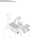
- FIG. 1 is an axonometric drawing of a robot vision measurement and control-based automatic rivet placement system according to the present invention.
- FIG. 2 is an axonometric drawing of a multi-functional end effector according to the present invention.
- FIG. 3 is a schematic diagram of a closed state of a cover plate component according to the present invention.
- FIG. 4 is a schematic diagram of an open state of a cover plate component according to the present invention.
- FIG. 5 is a schematic diagram of an open state of a rivet blowing mechanism according to the present invention.
- FIG. 6 is a schematic diagram of a closed state of a rivet blowing mechanism according to the present invention.
- FIG. 7 is a sectional view of a detection disk according to the present invention.
- FIG. 8 is an axonometric drawing of a detection disk according to the present invention.
- the wording “include” used in the description of the present invention refers to the presence of the features, integers, steps, operations, elements and/or components, but does not exclude the presence or addition of one or more other features, integers, steps, operations, elements, components and/or their combinations. It should be understood that when it is referred to as being “connected” or “coupled” to another element, an element can be directly connected or coupled to other elements or intermediate elements may also exist. In addition, for the presence of components such as communication electronics, the “connected” or “coupled” used herein may include wireless connection or coupling. As used herein, the wording “and/or” includes any unit and all combinations of one or more of the associated listed items.
- the embodiments of the present invention provide a robot vision-based automatic rivet placement system, as shown in FIG. 1 , including:
- an industrial robot 1
- a multi-functional end effector 2
- a cover plate component 3
- a rivet blowing mechanism 4
- a detection disk 5
- a vacuum generator 6
- a valve group 7
- a control cabinet 8
- a frame 9
- a rivet holding tray 10
- an industrial personal computer 11
- the industrial robot ( 1 ), the cover plate component ( 3 ), the rivet blowing mechanism ( 4 ), the detection disk ( 5 ), the vacuum generator ( 6 ), the valve group ( 7 ) and the rivet holding tray ( 10 ) are installed on the frame ( 9 ).
- the multi-functional end effector ( 2 ) is composed of a flange disk ( 12 ), a support frame ( 13 ), an industrial charge coupled device (CCD) camera ( 14 ), a laser displacement sensor ( 15 ), a spring ( 16 ), a mixing rod ( 17 ) and a vacuum nozzle ( 18 ).
- the multi-functional end effector ( 2 ) is connected to a terminal end of the industrial robot ( 1 ) via the flange disk ( 12 ).
- the support frame ( 13 ) is used to fix elements on the multi-functional end effector ( 2 ).
- the industrial CCD camera ( 14 ) and the laser displacement sensor ( 15 ) form a rivet space pose measurement module.
- the industrial CCD camera ( 14 ) is installed directly in front of the support frame ( 13 ) and is used to acquire a rivet image.
- the rivet image is used to measure a planimetric position of a rivet.
- the laser displacement sensor ( 15 ) is installed on a side surface of the support frame ( 13 ) and is used to measure a rivet depth.
- the spring ( 16 ) and the mixing rod ( 17 ) form an elastic mixing mechanism used to mix the rivet holding tray ( 10 ) to uniformly distribute the rivets.
- the vacuum nozzle ( 18 ) is installed below the support frame ( 13 ) and is used to pick up or place a rivet.
- the elastic mixing mechanism on the multi-functional end effector can mix the rivet holding tray to uniformly distribute the rivets, which is helpful for a robot to fast identify the rivets.
- 35 rivet holding trays ( 10 ) are provided in total, and are arranged in five rows and seven columns, so as to meet a rivet placement requirement of most standard rivets in current aircraft manufacturing. More kinds of rivet models are built in a vision processing program of the industrial personal computer, so that the robot can identify, pick up and convey more types of rivets. The flexibility of the rivet placement system is significantly improved.
- a binocular vision pick-up terminal end is used to identify and pick up various types of rivets.
- the binocular vision can only identify rivets in a single-layer sparse distribution state, which cannot adapt to a situation where rivets are crossed and stacked layer by layer, and the identification rate of rivets is low.
- an air claw is used to pick up the rivets, leading to the disadvantages that pick-up is unreliable, excessive rivets are easy to pick up, and there are rivets which are not picked up.
- parameters, such as the diameter and the length, of the rivets cannot be measured.
- the rivets in a holding rack need to be conveyed to a pick-up station before visual inspection and pick-up are performed, so that the overall working efficiency is low.
- a visually guided robot can directly unpack and take out rivets in a rivet holding box, so that the step of directionally arranging the rivets is eliminated; therefore, the efficiency and the speed are high.
- the vacuum nozzle is used to pick up the rivets.
- the nozzle can be accurately positioned on the surface of the rivet, and a soft silica gel suction cup forms wrappage on a rivet cylinder, so that the rivet is grasped more firmly, and the problems that excessive rivets are easy to pick up, the rivets are easy to fall off, and the like when a traditional air claw is used to pick up the rivets are solved.
- a negative pressure feedback mechanism of the vacuum generator can monitor in real time whether the rivets are picked up successfully.
- the robot automatically re-executes an action of picking up the rivets to ensure that the robot can pick up the rivets.
- the laser displacement sensor cooperates with the industrial CCD camera to measure a spatial position of a rivet, so that the problem that a monocular camera cannot measure a distance of the rivet in a depth direction is solved; the measurement accuracy in the depth direction is high, and the accuracy of the position for rivet pick-up is guaranteed.
- the cover plate component ( 3 ) is composed of a guide rail component ( 19 ), a first connecting piece ( 20 ), a rivet feeding tube ( 21 ), a cover plate ( 22 ), a pneumatic sliding table ( 23 ), a limiting block ( 24 ) and a second connecting piece ( 25 ).
- the first connecting piece ( 20 ) is used to connect the guide rail component ( 19 ) and the cover plate ( 22 );
- the second connecting piece ( 25 ) is used to connect the pneumatic sliding table ( 23 ) and the cover plate ( 22 );
- the limiting block ( 24 ) is used to limit the position of the cover plate ( 22 ).
- the rivet feeding tube ( 21 ) is located directly below the cover plate ( 22 ).
- the pneumatic sliding table ( 23 ) pushes out the cover plate ( 22 )
- an inner hole of the rivet feeding tube ( 21 ) is aligned with a rivet inlet hole of the cover plate ( 22 ); and at this time, the robot can put a rivet into the rivet feeding tube.
- the pneumatic sliding table ( 23 ) withdraws the cover plate ( 22 )
- the inner hole of the rivet feeding tube ( 21 ) is sealed by the cover plate ( 22 ), and the rivet and other debris cannot enter the rivet feeding tube.
- the cover plate ( 22 ) is provided with four holes having different diameters. Edges of the four holes are respectively welded with arc-shaped opening retainer rings to prevent the rivet from popping out during placement.
- the rivet blowing mechanism ( 4 ) is composed of an air pipe fast connector ( 26 ), a valve core ( 27 ), a valve body ( 28 ), a pipe clamp ( 29 ), sealing rings ( 31 ), a rivet placement pipe ( 32 ), a floating connector ( 33 ), and an air cylinder ( 34 ).
- the valve core ( 27 ), the sealing rings ( 31 ) and the valve body ( 28 ) form a valve of the rivet blowing mechanism ( 4 ).
- the air pipe fast connector ( 26 ) is connected to a left end of the valve core ( 27 ).
- the floating connector ( 33 ) connects a right end of the valve core ( 27 ) and a piston rod of the air cylinder ( 34 ).
- the pipe clamp ( 29 ) connects the valve body ( 28 ) and the rivet placement pipe ( 32 ).
- the rivet feeding tube ( 21 ) is installed at an upper end of the valve body ( 28 ).
- Two sealing rings ( 31 ) are respectively sleeved in two grooves of the valve core ( 27 ).
- the valve core ( 27 ) is of an elongate cylindrical structure; the valve core ( 27 ) is provided with an air path channel and a rivet channel; and the air path channel is connected to the air pipe fast connector ( 26 ).
- the detection disk ( 5 ) is composed of an air blowing nozzle ( 35 ), an air nozzle support frame ( 36 ), an acrylic plate ( 37 ), a light source support frame ( 39 ), a backlight source ( 40 ), a hollow round disk ( 41 ), a baffle plate ( 42 ) and a waste box ( 43 ).
- the transparent disk-shaped acrylic plate ( 37 ) and the hollow round disk ( 41 ) are fixed above a table plate ( 38 ) and directly opposite to the backlight source ( 40 ); and the baffle plate ( 42 ) and the waste box ( 43 ) are placed on a right side of the hollow round disk ( 41 ).
- the air nozzle support frame ( 36 ) is used to fix the air blowing nozzle ( 35 ) on the hollow round disk ( 41 ), and the light source support frame ( 39 ) is used to fix the backlight source ( 40 ) below the table plate ( 38 ).
- the embodiments of the present invention provide a robot vision-based automatic rivet placement method.
- the automatic rivet placement method is applied to the robot vision-based automatic rivet placement system in the present embodiment.
- the automatic rivet placement system is composed of an industrial robot ( 1 ), a multifunctional end effector ( 2 ), a cover plate component ( 3 ), a rivet blowing mechanism ( 4 ), a detection disk ( 5 ), a vacuum generator ( 6 ), a valve group ( 7 ), a control cabinet ( 8 ), a frame ( 9 ), a rivet holding tray ( 10 ) and an industrial personal computer ( 11 ).
- the method includes the following steps:
- the secondary positioning measurement strategy used in the step b specifically includes the following sub-steps:
- the step b is re-executed till suction is successful when a negative pressure feedback sensor of the vacuum generator ( 6 ) monitors a suction failure.
- the secondary positioning measurement strategy used solves the problem that the monocular camera cannot measure positions of rivets on different depth planes, such that even if rivets are on different depth planes, the positions of the rivets can also be accurately measured.
- step c includes the following sub-steps:
- step d includes the following sub-steps:
- the method also includes the following steps: projecting, by the industrial robot ( 1 ), laser to four corners of the rivet holding tray ( 10 ) through a laser displacement sensor ( 15 ) to obtain an average value of a rivet depth in the rivet holding tray ( 10 ); acquiring a residual number of rivets in the rivet holding tray ( 10 ) according to the average value of the rivet depth; and if the residual number is less than a preset value, sending, by the industrial personal computer ( 11 ), a replenishment prompt signal.
- the laser displacement sensor ( 15 ) in the present embodiment may also be used to measure the residual number of rivets in the rivet holding tray ( 10 ), and the industrial robot ( 1 ) is controlled to project the laser to the four corners of the rivet holding tray ( 10 ) to calculate the average value of the rivet depth and measure the residual number of the rivets.
- the industrial personal computer ( 11 ) would prompt a worker to replenish rivets in time.
- the residual number of the rivets is monitored in real time through the laser displacement sensor, realizing intelligent management of the automatic rivet placement system.
Landscapes
- Engineering & Computer Science (AREA)
- Mechanical Engineering (AREA)
- Robotics (AREA)
- Multimedia (AREA)
- Automatic Assembly (AREA)
- Manipulator (AREA)
Abstract
Description
-
- step a: sending, by an industrial personal computer (11), a control signal to an industrial robot (1), and controlling, by a robot controller in a control cabinet (8), the industrial robot (1) according to the control signal to move to a position directly above the rivet holding tray (10) corresponding to a model number of rivets to be picked up, wherein the model number of the rivets to be picked up is recorded in the control signal;
- step b: measuring, by a multi-functional end effector (2), a position of a rivet in the rivet holding tray (10) through a secondary positioning measurement strategy, executing a pick-up action, and then placing the picked rivet into a detection disk (5);
- step c: measuring, by the multi-functional end effector (2), a diameter, a length and a position posture of the rivet in the detection disk (5), and determining a defective product according to a measurement result; and
- step d: picking up, by the industrial robot (1), the rivet in the detection disk (5) and feeding the rivet into a rivet blowing mechanism (4); and blowing, by the rivet blowing mechanism (4), the received rivet to automatic drilling and riveting equipment.
-
- step a: sending, by the industrial personal computer (11), a control signal to the industrial robot (1), and controlling, by a robot controller in the control cabinet (8), the industrial robot (1) according to the control signal to move to a position directly above the rivet holding tray (10) corresponding to a model number of rivets to be picked up, wherein the model number of the rivets to be picked up is recorded in the control signal;
- step b: measuring, by the multi-functional end effector (2), a position of a rivet in the rivet holding tray (10) through a secondary positioning measurement strategy, executing a pick-up action, and then placing the picked rivet into the detection disk (5);
- step c: measuring, by the multi-functional end effector (2), a diameter, a length and a position posture of the rivet in the detection disk (5), and determines a defective product according to a measurement result; and
- step d: picking up, by the industrial robot (1), the rivet in the detection disk (5) and feeding the rivet into the rivet blowing mechanism (4); and blowing, by the rivet blowing mechanism (4), the received rivet to automatic drilling and riveting equipment to complete one working cycle.
-
- transmitting a photographed rivet image to the industrial personal computer (11) through an industrial CCD camera (14);
- pre-processing, by a vision processing program in the industrial personal computer (11), the rivet image to obtain an estimated value of a position of the rivet in a horizontal direction, and sending, by the industrial personal computer (11), the estimated value to the industrial robot (1);
- adjusting, by the industrial robot (1), the pose according to the estimated value to enable the industrial CCD camera (14) to move to a position above the photographed rivet, and taking a picture again to obtain an accurate value of the position of the rivet in the horizontal direction;
- adjusting, by the industrial robot (1), the pose according to the accurate value such that a laser beam of a laser displacement sensor (15) is projected on the photographed rivet to obtain a position of the photographed rivet in a depth direction, and then feeding back the position in the depth direction to the industrial personal computer (11); and sending, by the industrial personal computer (11), the position in the depth direction to the industrial robot (1).
- adjusting, by the industrial robot (1), the pose according to the position in the depth direction, such that a vacuum nozzle (18) moves to a surface of the photographed rivet, and then turning on the vacuum generator (6); and
- sucking, by a suction cup of the vacuum nozzle (18), the photographed rivet, taking out, by the industrial robot (1), the photographed rivet from the rivet holding tray (10) and placing the photographed rivet in the detection disk (5).
-
- taking, by an industrial CCD camera (14), a picture and transmits the rivet image to the industrial personal computer (11), after a backlight source (40) is turned on;
- pre-processing, by a vision processing program in the industrial personal computer (11), the rivet image, and measures the diameter, the length and the direction of the rivet in the rivet image by means of a template matching technology; and
- if the rivet in the rivet image does not conform to a model number recorded in the control signal, and/or the rivet in the rivet image is defective, triggering an air blowing nozzle (35) to blow air to blow the defective rivet into a waste box (43).
-
- pushing out a cover plate (22) to open a rivet inlet and turn on a valve, after the industrial robot (1) picks up the rivet in the detection disk (5), as shown in
FIG. 4 ; - opening the valve, and feeding, by the industrial robot (1), the rivet (30) into the rivet blowing mechanism (4), with a posture of rivet head upward, as shown in
FIG. 5 ; and then retracting the cover plate (22) to seal the rivet inlet and close the valve, as shown inFIG. 3 ; and - closing the valve, and introducing high-pressure air into an air path channel of a valve core (27) to blow the rivet (30) to the automatic drilling and riveting equipment, as shown in
FIG. 6 .
- pushing out a cover plate (22) to open a rivet inlet and turn on a valve, after the industrial robot (1) picks up the rivet in the detection disk (5), as shown in
Claims (10)
Applications Claiming Priority (3)
| Application Number | Priority Date | Filing Date | Title |
|---|---|---|---|
| CN201910620737.6A CN110523909B (en) | 2019-07-10 | 2019-07-10 | Automatic nail feeding system and method based on robot vision |
| CN201910620737.6 | 2019-07-10 | ||
| PCT/CN2019/109866 WO2021003858A1 (en) | 2019-07-10 | 2019-10-08 | Robot vision-based automatic rivet placement system and method |
Publications (2)
| Publication Number | Publication Date |
|---|---|
| US20210346939A1 US20210346939A1 (en) | 2021-11-11 |
| US11648604B2 true US11648604B2 (en) | 2023-05-16 |
Family
ID=68659570
Family Applications (1)
| Application Number | Title | Priority Date | Filing Date |
|---|---|---|---|
| US17/289,020 Active US11648604B2 (en) | 2019-07-10 | 2019-10-08 | Robot vision-based automatic rivet placement system and method |
Country Status (3)
| Country | Link |
|---|---|
| US (1) | US11648604B2 (en) |
| CN (1) | CN110523909B (en) |
| WO (1) | WO2021003858A1 (en) |
Families Citing this family (31)
| Publication number | Priority date | Publication date | Assignee | Title |
|---|---|---|---|---|
| CN110834186B (en) * | 2019-12-17 | 2024-06-04 | 郑州瑞盛德机械设备有限公司 | Material collecting and distributing system for equipment assembly and collecting and distributing method thereof |
| CN111689218B (en) * | 2020-06-04 | 2021-11-05 | 九江学院 | Product emptying method and system, mobile terminal and storage medium |
| CN112008474A (en) * | 2020-08-27 | 2020-12-01 | 长春理工大学 | Automatic drilling and riveting and hole site and hole shape parameter online detection device |
| CN114435951B (en) * | 2021-02-23 | 2024-01-05 | 昆山市奥森维尔自动化设备有限公司 | Automatic typesetting equipment for space rings |
| CN113042675A (en) * | 2021-03-31 | 2021-06-29 | 南京航空航天大学 | Multifunctional end effector for automatic nail grabbing robot and use method thereof |
| CN113253351A (en) * | 2021-04-07 | 2021-08-13 | 重庆智能机器人研究院 | Rivet taking detection device, rivet taking machine and detection method |
| CN113618351B (en) * | 2021-07-02 | 2022-10-11 | 昆山阿普顿自动化系统有限公司 | Automatic material returned mechanism of pressure equipment mistake proofing |
| CN113458313B (en) * | 2021-07-29 | 2023-08-11 | 苏州瑞玛精密工业股份有限公司 | Automatic rivet identification and rivet placing device |
| CN114054664A (en) * | 2021-11-12 | 2022-02-18 | 上海先惠自动化技术股份有限公司 | Riveting is with sending nail and pressing nail mechanism and riveting system |
| CN113953438A (en) * | 2021-11-15 | 2022-01-21 | 东莞理工学院 | Automatic riveting equipment for lock ring |
| CN114029657A (en) * | 2021-11-23 | 2022-02-11 | 广州丰桥智能装备有限公司 | Flexible piece feeding system based on 3D vision guidance |
| CN114193142A (en) * | 2021-12-03 | 2022-03-18 | 苏州浪潮智能科技有限公司 | Grabbing device and method for assembling server cable and screw |
| FR3130174B1 (en) * | 2021-12-09 | 2024-01-12 | Seti Tec | Multi-tasking device comprising means of evacuation to a discard area of a rivet or temporary fastener identified as non-compliant |
| CN114102188B (en) * | 2021-12-21 | 2023-04-07 | 浙江西子势必锐航空工业有限公司 | Machining clamp and machining process for aviation component |
| CN114210757A (en) * | 2021-12-23 | 2022-03-22 | 东风汽车紧固件有限公司 | Automatic feeding device of cold extruding machine |
| CN114289670B (en) * | 2021-12-31 | 2023-05-05 | 苏州枭帝克精密钣金有限公司 | Manufacturing equipment and process for light high-strength car bottom |
| CN114425689B (en) * | 2022-01-21 | 2023-12-29 | 苏州宏瑞达新能源装备有限公司 | Junction box cover assembling equipment |
| CN115415787B (en) * | 2022-04-14 | 2024-08-06 | 湖南航智科技有限公司 | Explosion-proof type automatic assembly special plane system |
| CN117283357A (en) * | 2022-04-21 | 2023-12-26 | 杭州垦驱智能科技有限公司 | Structure and control method of intelligent processing unit of intelligent production line |
| CN117289654A (en) * | 2022-04-21 | 2023-12-26 | 杭州垦驱智能科技有限公司 | Structure and control method of intelligent detection unit of intelligent production line |
| CN114850511B (en) * | 2022-05-07 | 2024-06-18 | 四川竞本科技有限公司 | Workpiece turning equipment based on manipulator circulation operation |
| CN117340920A (en) * | 2022-06-27 | 2024-01-05 | 宝山钢铁股份有限公司 | End effector for capping robot of torpedo hot metal mixer car and capping method of end effector |
| CN115139240A (en) * | 2022-06-29 | 2022-10-04 | 和信精密科技(吴江)有限公司 | Quick positioning system |
| CN115139074B (en) * | 2022-07-07 | 2023-11-03 | 华南理工大学 | Mechanical arm assembly system and method for flexible tab-plastic shell of mobile phone lithium battery |
| CN115464373B (en) * | 2022-08-23 | 2023-10-03 | 盐城家安乐自动化科技有限公司 | Automatic mounting equipment for automobile panel nuts and working method thereof |
| CN115229803B (en) * | 2022-09-19 | 2023-02-28 | 国网浙江宁波市鄞州区供电有限公司 | Integrated mechanical arm tail end executive component based on visual recognition and control method thereof |
| CN116604329B (en) * | 2023-04-27 | 2024-06-11 | 浙江奇碟汽车零部件有限公司 | Automatic assembling system of double-plate clutch assembly |
| CN116833360B (en) * | 2023-07-20 | 2024-05-24 | 无锡超捷汽车连接技术有限公司 | Continuous spin riveting device for fixing support sleeve for vehicle |
| CN117124033A (en) * | 2023-08-18 | 2023-11-28 | 无锡一都科技有限公司 | Automatic assembly equipment for valve core of diesel oil nozzle |
| CN117484177B (en) * | 2023-12-29 | 2024-04-09 | 歌尔股份有限公司 | Assembling equipment and control method thereof |
| CN118073167B9 (en) * | 2024-04-19 | 2024-09-03 | 南京原磊纳米材料有限公司 | Multi-piece type automatic cavity taking and placing mechanism capable of preventing winding plating |
Citations (8)
| Publication number | Priority date | Publication date | Assignee | Title |
|---|---|---|---|---|
| US5727300A (en) * | 1995-02-07 | 1998-03-17 | The Boeing Company | Fastener verification system |
| US20040148748A1 (en) * | 2002-11-21 | 2004-08-05 | Woyciesjes James N. | Modular rivet tool |
| US20130085605A1 (en) * | 2011-10-04 | 2013-04-04 | Kabushiki Kaisha Yaskawa Denki | Robot system and method for producing a to-be-processed material |
| CN109290506A (en) * | 2018-08-13 | 2019-02-01 | 南京航空航天大学 | A kind of automatic nail feeding system and its working method based on robot |
| US20190291171A1 (en) * | 2016-05-13 | 2019-09-26 | Broetje-Automation Gmbh | Method for filling a rivet cartridge with rivet elements |
| US20200108438A1 (en) * | 2017-04-03 | 2020-04-09 | Broetje-Automation Gmbh | Method for supplying a riveting machine with rivet elements |
| US20200282449A1 (en) * | 2017-05-12 | 2020-09-10 | Broejte-Automation GmbH | Rivet element supply unit |
| US20210291256A1 (en) * | 2019-06-14 | 2021-09-23 | Meishan Crrc Fastening System Co., Ltd | Riveting robot system |
Family Cites Families (11)
| Publication number | Priority date | Publication date | Assignee | Title |
|---|---|---|---|---|
| DE102005006795A1 (en) * | 2005-02-14 | 2006-08-24 | Newfrey Llc, Newark | Method and device for feeding connecting elements to a processing device |
| CN103112062B (en) * | 2013-03-14 | 2014-12-24 | 昆山恒基制刷机械有限公司 | Air feeding system of nailing machine |
| CN103743350A (en) * | 2013-12-30 | 2014-04-23 | 江苏保力自动化科技有限公司 | Parallel projection method and parallel projection device for detecting diameter and thickness of blank cake |
| CN104708322B (en) * | 2015-02-15 | 2017-03-29 | 南京航空航天大学 | A kind of multi-functional drill riveting executor and its method of work |
| CN105197584B (en) * | 2015-07-10 | 2017-04-12 | 上海微松工业自动化有限公司 | Automatic feeding device with robots |
| CN106044120B (en) * | 2016-06-21 | 2018-08-24 | 南京航空航天大学 | A kind of continuous nail feeding machanism of automatic Drilling/Riveting system |
| CN106680287B (en) * | 2016-12-28 | 2020-07-03 | 无锡浩远视觉科技有限公司 | Visual detection method for step defects of bearing rivet |
| DE102017101705A1 (en) * | 2017-01-30 | 2018-08-02 | Newfrey Llc | Joining device, loading station, feeding arrangement and method for loading a magazine |
| CN107138669B (en) * | 2017-03-07 | 2018-11-27 | 芜湖仅一机械有限公司 | A kind of feeding riveting machine arm of steering wheel die casting automatic riveting press |
| CN208731985U (en) * | 2018-09-14 | 2019-04-12 | 江苏德诺蒙玛机电科技有限公司 | One kind blowing spike devices |
| CN109225915B (en) * | 2018-11-02 | 2019-10-11 | 西南交通大学 | A kind of rivet quality classification and Automated Sorting System and method |
-
2019
- 2019-07-10 CN CN201910620737.6A patent/CN110523909B/en active Active
- 2019-10-08 WO PCT/CN2019/109866 patent/WO2021003858A1/en active Application Filing
- 2019-10-08 US US17/289,020 patent/US11648604B2/en active Active
Patent Citations (8)
| Publication number | Priority date | Publication date | Assignee | Title |
|---|---|---|---|---|
| US5727300A (en) * | 1995-02-07 | 1998-03-17 | The Boeing Company | Fastener verification system |
| US20040148748A1 (en) * | 2002-11-21 | 2004-08-05 | Woyciesjes James N. | Modular rivet tool |
| US20130085605A1 (en) * | 2011-10-04 | 2013-04-04 | Kabushiki Kaisha Yaskawa Denki | Robot system and method for producing a to-be-processed material |
| US20190291171A1 (en) * | 2016-05-13 | 2019-09-26 | Broetje-Automation Gmbh | Method for filling a rivet cartridge with rivet elements |
| US20200108438A1 (en) * | 2017-04-03 | 2020-04-09 | Broetje-Automation Gmbh | Method for supplying a riveting machine with rivet elements |
| US20200282449A1 (en) * | 2017-05-12 | 2020-09-10 | Broejte-Automation GmbH | Rivet element supply unit |
| CN109290506A (en) * | 2018-08-13 | 2019-02-01 | 南京航空航天大学 | A kind of automatic nail feeding system and its working method based on robot |
| US20210291256A1 (en) * | 2019-06-14 | 2021-09-23 | Meishan Crrc Fastening System Co., Ltd | Riveting robot system |
Non-Patent Citations (2)
| Title |
|---|
| Li, Feiyu et al. "A Robot Rivet Feeding System for Automatic Drilling and Riveting" Aeronautical Manufacturing Technology, vol. 62, No. 10, May 15, 2019 (May 15, 2019), pp. 44-50* (Year: 2019). * |
| Translation of Li, Feiyu et al. (Year: 2019). * |
Also Published As
| Publication number | Publication date |
|---|---|
| WO2021003858A1 (en) | 2021-01-14 |
| CN110523909A (en) | 2019-12-03 |
| CN110523909B (en) | 2021-02-05 |
| US20210346939A1 (en) | 2021-11-11 |
Similar Documents
| Publication | Publication Date | Title |
|---|---|---|
| US11648604B2 (en) | Robot vision-based automatic rivet placement system and method | |
| CN106925996A (en) | A kind of earpiece grenadine automatic assembling | |
| CN103786008B (en) | Put nailing machine, for putting the suction nozzle of nailing machine and putting nail method | |
| CN209480687U (en) | A kind of on-line testing automation equipment | |
| CN109384037A (en) | A kind of on-line testing automation equipment | |
| CN109677867B (en) | Sorting device for preventing error in assembling of driving shaft retaining rings | |
| CN106002285A (en) | Automatic assembly line of stew-pan | |
| CN103335796B (en) | Full-automatic two logical air-tightness detection devices | |
| KR101537526B1 (en) | automatic apparatus for assemblying an O-ring to a prepiston | |
| CN109676342A (en) | A kind of hole sealing ring mounting device and hole sealing ring assembly machine | |
| CN103896025A (en) | Intelligent camera based flexible vibration transmission system and operating method thereof | |
| WO2024016116A1 (en) | Automatic assembly machine for breather valve | |
| CN102218721A (en) | Robot stator punching sheet transporting claw device | |
| CN107234375A (en) | A kind of method and apparatus of automatic set weldering circle | |
| CN205817288U (en) | A kind of automatic assembly line of saucepan | |
| CN208696575U (en) | A kind of photovoltaic cell perforating device | |
| CN107570990A (en) | A kind of car horn insulating part assembling and means for correcting | |
| CN210365813U (en) | Automatic production line for helium detection of oil tank | |
| CN107214108A (en) | A kind of Efficient intelligent produces and processes the method for work of system | |
| CN209303222U (en) | Automatic laser height detection apparatus | |
| CN107096727B (en) | A kind of intelligent machining system | |
| CN206575609U (en) | The concentric assembling fixture and magnetic circuit component automatic assembly equipment of magnetic circuit component | |
| CN110091181A (en) | A kind of package system and its operating method for automobile lamp | |
| CN209367214U (en) | General-using type lock pin disk automatic loading machine | |
| CN208187946U (en) | A kind of display screen detection device |
Legal Events
| Date | Code | Title | Description |
|---|---|---|---|
| AS | Assignment |
Owner name: NANJING UNIVERSITY OF AERONAUTICS AND ASTRONAUTICS, CHINA Free format text: ASSIGNMENT OF ASSIGNORS INTEREST;ASSIGNORS:TIAN, WEI;ZHENG, YI;ZHUANG, ZHIWEI;AND OTHERS;REEL/FRAME:056052/0213 Effective date: 20210329 |
|
| FEPP | Fee payment procedure |
Free format text: ENTITY STATUS SET TO UNDISCOUNTED (ORIGINAL EVENT CODE: BIG.); ENTITY STATUS OF PATENT OWNER: SMALL ENTITY |
|
| FEPP | Fee payment procedure |
Free format text: ENTITY STATUS SET TO SMALL (ORIGINAL EVENT CODE: SMAL); ENTITY STATUS OF PATENT OWNER: SMALL ENTITY |
|
| STPP | Information on status: patent application and granting procedure in general |
Free format text: DOCKETED NEW CASE - READY FOR EXAMINATION |
|
| STPP | Information on status: patent application and granting procedure in general |
Free format text: NON FINAL ACTION MAILED |
|
| STPP | Information on status: patent application and granting procedure in general |
Free format text: RESPONSE TO NON-FINAL OFFICE ACTION ENTERED AND FORWARDED TO EXAMINER |
|
| STPP | Information on status: patent application and granting procedure in general |
Free format text: EX PARTE QUAYLE ACTION MAILED |
|
| STPP | Information on status: patent application and granting procedure in general |
Free format text: RESPONSE TO EX PARTE QUAYLE ACTION ENTERED AND FORWARDED TO EXAMINER |
|
| STPP | Information on status: patent application and granting procedure in general |
Free format text: NOTICE OF ALLOWANCE MAILED -- APPLICATION RECEIVED IN OFFICE OF PUBLICATIONS |
|
| STCF | Information on status: patent grant |
Free format text: PATENTED CASE |