US1163243A - Turbine-pump. - Google Patents
Turbine-pump. Download PDFInfo
- Publication number
- US1163243A US1163243A US81781114A US1914817811A US1163243A US 1163243 A US1163243 A US 1163243A US 81781114 A US81781114 A US 81781114A US 1914817811 A US1914817811 A US 1914817811A US 1163243 A US1163243 A US 1163243A
- Authority
- US
- United States
- Prior art keywords
- impeller
- pump
- flange
- pressure
- casing
- Prior art date
- Legal status (The legal status is an assumption and is not a legal conclusion. Google has not performed a legal analysis and makes no representation as to the accuracy of the status listed.)
- Expired - Lifetime
Links
- 230000004048 modification Effects 0.000 description 5
- 238000012986 modification Methods 0.000 description 5
- 239000007788 liquid Substances 0.000 description 3
- 238000010276 construction Methods 0.000 description 2
- 230000002706 hydrostatic effect Effects 0.000 description 2
- 239000000463 material Substances 0.000 description 2
- 239000004576 sand Substances 0.000 description 2
- 229910000897 Babbitt (metal) Inorganic materials 0.000 description 1
- 238000009825 accumulation Methods 0.000 description 1
- 230000007246 mechanism Effects 0.000 description 1
- 230000037452 priming Effects 0.000 description 1
- 230000017105 transposition Effects 0.000 description 1
- XLYOFNOQVPJJNP-UHFFFAOYSA-N water Substances O XLYOFNOQVPJJNP-UHFFFAOYSA-N 0.000 description 1
Images
Classifications
-
- F—MECHANICAL ENGINEERING; LIGHTING; HEATING; WEAPONS; BLASTING
- F04—POSITIVE - DISPLACEMENT MACHINES FOR LIQUIDS; PUMPS FOR LIQUIDS OR ELASTIC FLUIDS
- F04D—NON-POSITIVE-DISPLACEMENT PUMPS
- F04D29/00—Details, component parts, or accessories
- F04D29/18—Rotors
- F04D29/22—Rotors specially for centrifugal pumps
- F04D29/2261—Rotors specially for centrifugal pumps with special measures
- F04D29/2266—Rotors specially for centrifugal pumps with special measures for sealing or thrust balance
-
- Y—GENERAL TAGGING OF NEW TECHNOLOGICAL DEVELOPMENTS; GENERAL TAGGING OF CROSS-SECTIONAL TECHNOLOGIES SPANNING OVER SEVERAL SECTIONS OF THE IPC; TECHNICAL SUBJECTS COVERED BY FORMER USPC CROSS-REFERENCE ART COLLECTIONS [XRACs] AND DIGESTS
- Y10—TECHNICAL SUBJECTS COVERED BY FORMER USPC
- Y10S—TECHNICAL SUBJECTS COVERED BY FORMER USPC CROSS-REFERENCE ART COLLECTIONS [XRACs] AND DIGESTS
- Y10S415/00—Rotary kinetic fluid motors or pumps
- Y10S415/901—Drilled well-type pump
Definitions
- Patented D60. 7, 1915
- This invention relates to centrifugal pumps, more particularly to the vertical type, wherein the impeller is balanced by the equalizing pressure on both ends there. of, and also. relates to certainfeatures disclosed in my application filed July 17, 1913, Serial No. 779,410.
- the objects of this invention are to provide means for controlling the balaneing pressure ,on the suction side of the impeller; to construct the members subject to the greatest wear so that they maybe readlly replaced when excessive wear makes it desirable; to so design the pump that the partssubjeeted to the greatest wear may be formed of the most suitable material to resist wear, while the permanent parts may be formed of baser and more economical material.
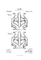
- Figure 1 is a vertical cross section of a centrifugal pump, having this invention incorporated therein.
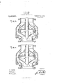
- Figs. 2, 8 and 4 illustrate modifications in the design and application of this invention as combined in the structure of centrifugal pumps.
- FIG. 1 Construction-In detail the construction of this invention as illustrated in Fig. 1 in eludes the base 1, hermetically attached to the casing 2.
- the casing and base are provided with the flanges 3 and lsurrounding the lower suction opening and the upper discharge opening respectively.
- the casing supports an internally spaced chamber wall 5, preferably cast integral with the casing to which it is attached by the hollow cored struts 6.
- the depending neck 7, provides a vertical bearing provided with the bushing 8, to receive the vertical shaft 9, journaled therein.
- the impeller 10 is fixed to the lower end of the shaft in any suitable manner and includes in its structure the open suction throat 11, having impelling planes 12, radiating therefrom in the usual manner.
- the annular flange 18 extends up wardly around the periphery of the impeller.
- the divid ng diaphragm l5 is attached to the annular base of the wall 5; this combination forming the upper chamber 16 and the lower pressure chamber 17.
- the diaphragm 15 is pro vided with the annular depending central rim 18, leaving the annular space or port 19 between it and the neck ,7. .
- Thecircumference of the diaphragm 15 is provided with the depending annular flange 20.
- This flange 20 cooperates with the flange 13, to partially seal the lower chamber; 21, within the casing.
- the relative positions of these two flanges may be varied as indicated, in ,these several modifications illustrated.
- To maintain the suetionwithin the casing in operation it is necessary to pack around the throat ll of the impeller. This is accomplished by the bushing 22 of suitable antifriction bearing metal, fixed within the base 1 and approximating contact with the neck23 of the impeller; whereby the inrushing liquid is forced to flow through the impeller only.
- the pump operates substantially as follows: These pumps are usually submerged, .or other means are provided for priming, or filling them with water or the liquid to be pumped; whenused in stages or. tandem the lower pump is submerged and those above discharge upward fromone tothe other. Obviously the weight of the shaft and attached mechanisms tends to force the impeller; downward, which tend ency is eounteraetedby the disposition of the impellerto rise in cutting through the liquidin which it is rotating, other forces enter into the practice of this art, that are sufliciently well known to those skilled therein to render superfluous a lengthy description of the necessity for balancing the pressure on both sides of the impeller.
- the hydrostatic head or pressure in the casing 21 leaks between the flanges 13 and 20 into the chamber 17, until the pressure therein equals the pressure in the casing, restoring the normal tendency of the propeller to descend, which opens a space between the rim 18, and the flange 14, permitting the escape of the pressure within the chamber 17 through the annular space 19 into the upper chamber 16, that is open to atmospheric pressure or to the medium within which the pump is submerged through the hollow struts 6.
- the tendency of the impeller to drop is counteracted by its lifting tendency in cutting through the liquid, and also by the lifting tendency of the hydrostatic head confined within the base 1, displacing the impeller upward.
- Frictional contact between the rim 18 and the flange let, the flanges 13 and 20, and the bushing 22 and the throat 23 represent the wearing parts upon which the balance pressure system depends and all these parts are readily removable for replacement.
- the sand cap 24 overhangs the upper end of the bushing 8 to prevent the entrance of sand at this point into the main bearing of the drive shaft.
- Fig. 2 shows the depending flange 20 and 13 transposed, as compared in the structure illustrated in Fig. 1; the advantage in this transposition is the attainment of greater length of the vanes 12*.
- Fig- 3 shows a variation in the diaphragm 15 which is screwed into the neck 7 and has theopenings 19 located near the periphery.
- These openings or ports comprise depending tubes formed integrally with thediaphragm at the proper intervals; the opening 19 being closed by the flange 149 formed adjacent to the flange 13 on the impeller.
- the modification shown in Fig. 4 comprises the diaphragm 15 keyed onto the neck 7 and provided with a depending flange 20 having the ports 19 located adjacent thereto at intervals; these ports are closed by the flange 1r projecting inward from the lines 13 on the periphery of the impeller.
- a centrifugal pump including a casing having an upper chamber therein closed by a removable diaphragm having a central opening, a flange on the impeller of the pump adapted to close said opening, flanges on said impeller and said diaphragm, cooperating to form a pressure chamber in said impeller.
- Centrifugal pump including a casing having an upper chamber therein, closed by a removable diaphragm having a central opening, a flange on the impeller of the pump surrounding the shaft thereof adapted to close said central opening and forming thereby a pressure chamber in said impeller.
- a centrifugal pump including a casing having an upper chamber therein, closed by a removable diaphragm having a central opening, a flange on the impeller of the pump surrounding the shaft thereof adapted to close said central opening, oppositely projecting flanges on said impeller and said diaphragm, cooperating to form a pressure chamber in said impeller.
Landscapes
- Engineering & Computer Science (AREA)
- Mechanical Engineering (AREA)
- General Engineering & Computer Science (AREA)
- Structures Of Non-Positive Displacement Pumps (AREA)
Description
F. W. KROGH.
TURBINE PUMP.
APPLICATION FILED FEB. 10. 1914.
Patented D60. 7, 1915.
2 SHEETS-SHEET 1 will/Ill V Il 34 INVENTOR.
WITNESSES.
ATTO R N EY.
COLUMBIA VLANOGRAPH c0., WASHINGTON, D. c.
F. W. KROGH.
TURBINE PUMP.
APPLICATION FILED FEB. 10. 1914. 1,163,243. Patented Dec.7,1915.
2 SHEETS-SHEET 2.
WITNESSES.
ATTORNEY.
-Cm|iMUIA PLANDGRAPH CO WASHINCITON. D. t
a j nnrr STATES Arnnr @FFIQ.
FERDINAND W. KROGH, or SAN rnAnoIseo', CALIFORNIA.
TURBINE-PUMP.
To all whom it may concern: I
Be it known that I, FERDINAND W Knoon, of San Francisco, California, have invented certain new and useful Improvements in Turbine-Pumps, whereof the following is a specification. v
, This invention relates to centrifugal pumps, more particularly to the vertical type, wherein the impeller is balanced by the equalizing pressure on both ends there. of, and also. relates to certainfeatures disclosed in my application filed July 17, 1913, Serial No. 779,410.
.Among the objects of this invention are to provide means for controlling the balaneing pressure ,on the suction side of the impeller; to construct the members subject to the greatest wear so that they maybe readlly replaced when excessive wear makes it desirable; to so design the pump that the partssubjeeted to the greatest wear may be formed of the most suitable material to resist wear, while the permanent parts may be formed of baser and more economical material. I
Other objects and advantages will appear in the accompanying two sheets of drawings and in the description thereof.
In the drawings, Figure 1 is a vertical cross section of a centrifugal pump, having this invention incorporated therein. Figs. 2, 8 and 4 illustrate modifications in the design and application of this invention as combined in the structure of centrifugal pumps.
Construction-In detail the construction of this invention as illustrated in Fig. 1 in eludes the base 1, hermetically attached to the casing 2. The casing and base are provided with the flanges 3 and lsurrounding the lower suction opening and the upper discharge opening respectively. The casing supports an internally spaced chamber wall 5, preferably cast integral with the casing to which it is attached by the hollow cored struts 6. The depending neck 7, provides a vertical bearing provided with the bushing 8, to receive the vertical shaft 9, journaled therein. The impeller 10 is fixed to the lower end of the shaft in any suitable manner and includes in its structure the open suction throat 11, having impelling planes 12, radiating therefrom in the usual manner. The annular flange 18 extends up wardly around the periphery of the impeller.
I The hub of the impeller is provided with the Specification of Letters lE"atent.
'01 seal its lower opening Patented'DecfiJ915.
Application filed February 10, 1914. Serial No. 817,811.
outwardly extending flange 14. The divid ng diaphragm l5 is attached to the annular base of the wall 5; this combination forming the upper chamber 16 and the lower pressure chamber 17. The diaphragm 15 is pro vided with the annular depending central rim 18, leaving the annular space or port 19 between it and the neck ,7. .Thecircumference of the diaphragm 15 is provided with the depending annular flange 20. This flange 20 cooperates with the flange 13, to partially seal the lower chamber; 21, within the casing. The relative positions of these two flanges may be varied as indicated, in ,these several modifications illustrated. To maintain the suetionwithin the casing in operation it is necessary to pack around the throat ll of the impeller. This is accomplished by the bushing 22 of suitable antifriction bearing metal, fixed within the base 1 and approximating contact with the neck23 of the impeller; whereby the inrushing liquid is forced to flow through the impeller only.
0pemte'on The pump operates substantially as follows: These pumps are usually submerged, .or other means are provided for priming, or filling them with water or the liquid to be pumped; whenused in stages or. tandem the lower pump is submerged and those above discharge upward fromone tothe other. Obviously the weight of the shaft and attached mechanisms tends to force the impeller; downward, which tend ency is eounteraetedby the disposition of the impellerto rise in cutting through the liquidin which it is rotating, other forces enter into the practice of this art, that are sufliciently well known to those skilled therein to render superfluous a lengthy description of the necessity for balancing the pressure on both sides of the impeller. The hydrostatic head or pressure in the casing 21 leaks between the flanges 13 and 20 into the chamber 17, until the pressure therein equals the pressure in the casing, restoring the normal tendency of the propeller to descend, which opens a space between the rim 18, and the flange 14, permitting the escape of the pressure within the chamber 17 through the annular space 19 into the upper chamber 16, that is open to atmospheric pressure or to the medium within which the pump is submerged through the hollow struts 6. The tendency of the impeller to drop is counteracted by its lifting tendency in cutting through the liquid, and also by the lifting tendency of the hydrostatic head confined within the base 1, displacing the impeller upward. The gradual accumulation and release of the pressure of the chamber 17 tends to equalize all counter forces; whereby the impeller is caused to float in its operation, removing end thrust in either direction. Frictional contact between the rim 18 and the flange let, the flanges 13 and 20, and the bushing 22 and the throat 23 represent the wearing parts upon which the balance pressure system depends and all these parts are readily removable for replacement. The sand cap 24: overhangs the upper end of the bushing 8 to prevent the entrance of sand at this point into the main bearing of the drive shaft.
The modification in Fig. 2 shows the depending flange 20 and 13 transposed, as compared in the structure illustrated in Fig. 1; the advantage in this transposition is the attainment of greater length of the vanes 12*.
The modification illustrated in Fig- 3 shows a variation in the diaphragm 15 which is screwed into the neck 7 and has theopenings 19 located near the periphery. These openings or ports comprise depending tubes formed integrally with thediaphragm at the proper intervals; the opening 19 being closed by the flange 149 formed adjacent to the flange 13 on the impeller.
The modification shown in Fig. 4: comprises the diaphragm 15 keyed onto the neck 7 and provided with a depending flange 20 having the ports 19 located adjacent thereto at intervals; these ports are closed by the flange 1r projecting inward from the lines 13 on the periphery of the impeller.
Having thus described my invention, and an embodiment of it, in the full, clear and exact terms required by law, and knowing that it comprises novel, useful and valuable improvements in the art to which it pertains, I here state that I do not wish to be limited to the precise construction and arrangement of the several parts, as herein set forth, as the same may be variously modified by a skilled mechanic without departing from the spirit of the invention.
What I claim and desire to secure by Letters Patent of the United States is the following, to wit:
1. A centrifugal pump including a casing having an upper chamber therein closed by a removable diaphragm having a central opening, a flange on the impeller of the pump adapted to close said opening, flanges on said impeller and said diaphragm, cooperating to form a pressure chamber in said impeller.
2. Centrifugal pump including a casing having an upper chamber therein, closed by a removable diaphragm having a central opening, a flange on the impeller of the pump surrounding the shaft thereof adapted to close said central opening and forming thereby a pressure chamber in said impeller.
3. A centrifugal pump including a casing having an upper chamber therein, closed by a removable diaphragm having a central opening, a flange on the impeller of the pump surrounding the shaft thereof adapted to close said central opening, oppositely projecting flanges on said impeller and said diaphragm, cooperating to form a pressure chamber in said impeller.
In testimony that I claim the foregoing I have hereto set my hand this 20th day of January 1914, in the presence of witnesses.
FERDINAND W. KROGH.
Witnesses L. M. 'WILLIAMs, MJMARKEL.
Copies of this patent may be obtained for five cents each, by addressing the Commissioner of Patents, Washington, D. C.
Priority Applications (1)
| Application Number | Priority Date | Filing Date | Title |
|---|---|---|---|
| US81781114A US1163243A (en) | 1914-02-10 | 1914-02-10 | Turbine-pump. |
Applications Claiming Priority (1)
| Application Number | Priority Date | Filing Date | Title |
|---|---|---|---|
| US81781114A US1163243A (en) | 1914-02-10 | 1914-02-10 | Turbine-pump. |
Publications (1)
| Publication Number | Publication Date |
|---|---|
| US1163243A true US1163243A (en) | 1915-12-07 |
Family
ID=3231273
Family Applications (1)
| Application Number | Title | Priority Date | Filing Date |
|---|---|---|---|
| US81781114A Expired - Lifetime US1163243A (en) | 1914-02-10 | 1914-02-10 | Turbine-pump. |
Country Status (1)
| Country | Link |
|---|---|
| US (1) | US1163243A (en) |
Cited By (1)
| Publication number | Priority date | Publication date | Assignee | Title |
|---|---|---|---|---|
| US4049361A (en) * | 1975-05-08 | 1977-09-20 | Allis-Chalmers Corporation | Runner seals for hydraulic turbines |
-
1914
- 1914-02-10 US US81781114A patent/US1163243A/en not_active Expired - Lifetime
Cited By (1)
| Publication number | Priority date | Publication date | Assignee | Title |
|---|---|---|---|---|
| US4049361A (en) * | 1975-05-08 | 1977-09-20 | Allis-Chalmers Corporation | Runner seals for hydraulic turbines |
Similar Documents
| Publication | Publication Date | Title |
|---|---|---|
| US3265001A (en) | Centrifugal pump | |
| US3079605A (en) | Centrifugal pump with double mechanical seal | |
| CA2119147A1 (en) | Deep well electrical submersible pump with uplift generating impeller means | |
| US1334461A (en) | Centrifugal pump | |
| US1163243A (en) | Turbine-pump. | |
| US3698830A (en) | Vertical centrifugal suction pump | |
| US1146078A (en) | Balancing means for centrifugal pumps. | |
| US1065732A (en) | Centrifugal pump. | |
| US1385115A (en) | Centrifugal pump | |
| US1273913A (en) | Centrifugal pump. | |
| US6837677B2 (en) | Impeller sealing arrangement | |
| US1772862A (en) | Pump | |
| US845816A (en) | Centripetal-centrifugal pump and condenser. | |
| US1169266A (en) | Deep-well pump. | |
| US983137A (en) | Centrifugal pump. | |
| US948228A (en) | Centrifugal pump. | |
| US1345655A (en) | Screw-pump | |
| US1022425A (en) | Centrifugal pump. | |
| US666869A (en) | End-thrust counterbalance for centrifugal pumps and shafting. | |
| GB190900214A (en) | Improvements in Rotary Apparatus for Pumping or Propelling Liquids and Gases. | |
| US1367450A (en) | Vertical pump | |
| US2663262A (en) | Centrifugal pump with sealing device | |
| US681389A (en) | Centrifugal fan. | |
| US564897A (en) | Half to john richards | |
| US1163242A (en) | Centrifugal pump. |