US11631889B2 - Methods and materials for protection of sulfide glass solid electrolytes - Google Patents
Methods and materials for protection of sulfide glass solid electrolytes Download PDFInfo
- Publication number
- US11631889B2 US11631889B2 US17/248,225 US202117248225A US11631889B2 US 11631889 B2 US11631889 B2 US 11631889B2 US 202117248225 A US202117248225 A US 202117248225A US 11631889 B2 US11631889 B2 US 11631889B2
- Authority
- US
- United States
- Prior art keywords
- layer
- lithium
- metal
- protective
- various embodiments
- Prior art date
- Legal status (The legal status is an assumption and is not a legal conclusion. Google has not performed a legal analysis and makes no representation as to the accuracy of the status listed.)
- Active, expires
Links
Images


Classifications
-
- H—ELECTRICITY
- H01—ELECTRIC ELEMENTS
- H01M—PROCESSES OR MEANS, e.g. BATTERIES, FOR THE DIRECT CONVERSION OF CHEMICAL ENERGY INTO ELECTRICAL ENERGY
- H01M10/00—Secondary cells; Manufacture thereof
- H01M10/05—Accumulators with non-aqueous electrolyte
- H01M10/056—Accumulators with non-aqueous electrolyte characterised by the materials used as electrolytes, e.g. mixed inorganic/organic electrolytes
- H01M10/0561—Accumulators with non-aqueous electrolyte characterised by the materials used as electrolytes, e.g. mixed inorganic/organic electrolytes the electrolyte being constituted of inorganic materials only
- H01M10/0562—Solid materials
-
- C—CHEMISTRY; METALLURGY
- C03—GLASS; MINERAL OR SLAG WOOL
- C03C—CHEMICAL COMPOSITION OF GLASSES, GLAZES OR VITREOUS ENAMELS; SURFACE TREATMENT OF GLASS; SURFACE TREATMENT OF FIBRES OR FILAMENTS MADE FROM GLASS, MINERALS OR SLAGS; JOINING GLASS TO GLASS OR OTHER MATERIALS
- C03C17/00—Surface treatment of glass, not in the form of fibres or filaments, by coating
- C03C17/22—Surface treatment of glass, not in the form of fibres or filaments, by coating with other inorganic material
- C03C17/23—Oxides
-
- C—CHEMISTRY; METALLURGY
- C03—GLASS; MINERAL OR SLAG WOOL
- C03C—CHEMICAL COMPOSITION OF GLASSES, GLAZES OR VITREOUS ENAMELS; SURFACE TREATMENT OF GLASS; SURFACE TREATMENT OF FIBRES OR FILAMENTS MADE FROM GLASS, MINERALS OR SLAGS; JOINING GLASS TO GLASS OR OTHER MATERIALS
- C03C3/00—Glass compositions
- C03C3/12—Silica-free oxide glass compositions
- C03C3/16—Silica-free oxide glass compositions containing phosphorus
- C03C3/19—Silica-free oxide glass compositions containing phosphorus containing boron
-
- C—CHEMISTRY; METALLURGY
- C03—GLASS; MINERAL OR SLAG WOOL
- C03C—CHEMICAL COMPOSITION OF GLASSES, GLAZES OR VITREOUS ENAMELS; SURFACE TREATMENT OF GLASS; SURFACE TREATMENT OF FIBRES OR FILAMENTS MADE FROM GLASS, MINERALS OR SLAGS; JOINING GLASS TO GLASS OR OTHER MATERIALS
- C03C3/00—Glass compositions
- C03C3/32—Non-oxide glass compositions, e.g. binary or ternary halides, sulfides or nitrides of germanium, selenium or tellurium
- C03C3/321—Chalcogenide glasses, e.g. containing S, Se, Te
-
- C—CHEMISTRY; METALLURGY
- C03—GLASS; MINERAL OR SLAG WOOL
- C03C—CHEMICAL COMPOSITION OF GLASSES, GLAZES OR VITREOUS ENAMELS; SURFACE TREATMENT OF GLASS; SURFACE TREATMENT OF FIBRES OR FILAMENTS MADE FROM GLASS, MINERALS OR SLAGS; JOINING GLASS TO GLASS OR OTHER MATERIALS
- C03C4/00—Compositions for glass with special properties
- C03C4/18—Compositions for glass with special properties for ion-sensitive glass
-
- H—ELECTRICITY
- H01—ELECTRIC ELEMENTS
- H01B—CABLES; CONDUCTORS; INSULATORS; SELECTION OF MATERIALS FOR THEIR CONDUCTIVE, INSULATING OR DIELECTRIC PROPERTIES
- H01B1/00—Conductors or conductive bodies characterised by the conductive materials; Selection of materials as conductors
- H01B1/06—Conductors or conductive bodies characterised by the conductive materials; Selection of materials as conductors mainly consisting of other non-metallic substances
- H01B1/10—Conductors or conductive bodies characterised by the conductive materials; Selection of materials as conductors mainly consisting of other non-metallic substances sulfides
-
- H—ELECTRICITY
- H01—ELECTRIC ELEMENTS
- H01M—PROCESSES OR MEANS, e.g. BATTERIES, FOR THE DIRECT CONVERSION OF CHEMICAL ENERGY INTO ELECTRICAL ENERGY
- H01M10/00—Secondary cells; Manufacture thereof
- H01M10/05—Accumulators with non-aqueous electrolyte
- H01M10/052—Li-accumulators
- H01M10/0525—Rocking-chair batteries, i.e. batteries with lithium insertion or intercalation in both electrodes; Lithium-ion batteries
-
- H—ELECTRICITY
- H01—ELECTRIC ELEMENTS
- H01M—PROCESSES OR MEANS, e.g. BATTERIES, FOR THE DIRECT CONVERSION OF CHEMICAL ENERGY INTO ELECTRICAL ENERGY
- H01M50/00—Constructional details or processes of manufacture of the non-active parts of electrochemical cells other than fuel cells, e.g. hybrid cells
- H01M50/40—Separators; Membranes; Diaphragms; Spacing elements inside cells
- H01M50/403—Manufacturing processes of separators, membranes or diaphragms
-
- H—ELECTRICITY
- H01—ELECTRIC ELEMENTS
- H01M—PROCESSES OR MEANS, e.g. BATTERIES, FOR THE DIRECT CONVERSION OF CHEMICAL ENERGY INTO ELECTRICAL ENERGY
- H01M50/00—Constructional details or processes of manufacture of the non-active parts of electrochemical cells other than fuel cells, e.g. hybrid cells
- H01M50/40—Separators; Membranes; Diaphragms; Spacing elements inside cells
- H01M50/409—Separators, membranes or diaphragms characterised by the material
- H01M50/431—Inorganic material
- H01M50/434—Ceramics
- H01M50/437—Glass
-
- H—ELECTRICITY
- H01—ELECTRIC ELEMENTS
- H01M—PROCESSES OR MEANS, e.g. BATTERIES, FOR THE DIRECT CONVERSION OF CHEMICAL ENERGY INTO ELECTRICAL ENERGY
- H01M50/00—Constructional details or processes of manufacture of the non-active parts of electrochemical cells other than fuel cells, e.g. hybrid cells
- H01M50/40—Separators; Membranes; Diaphragms; Spacing elements inside cells
- H01M50/409—Separators, membranes or diaphragms characterised by the material
- H01M50/449—Separators, membranes or diaphragms characterised by the material having a layered structure
- H01M50/451—Separators, membranes or diaphragms characterised by the material having a layered structure comprising layers of only organic material and layers containing inorganic material
-
- H—ELECTRICITY
- H01—ELECTRIC ELEMENTS
- H01M—PROCESSES OR MEANS, e.g. BATTERIES, FOR THE DIRECT CONVERSION OF CHEMICAL ENERGY INTO ELECTRICAL ENERGY
- H01M50/00—Constructional details or processes of manufacture of the non-active parts of electrochemical cells other than fuel cells, e.g. hybrid cells
- H01M50/40—Separators; Membranes; Diaphragms; Spacing elements inside cells
- H01M50/409—Separators, membranes or diaphragms characterised by the material
- H01M50/449—Separators, membranes or diaphragms characterised by the material having a layered structure
- H01M50/457—Separators, membranes or diaphragms characterised by the material having a layered structure comprising three or more layers
-
- H—ELECTRICITY
- H01—ELECTRIC ELEMENTS
- H01M—PROCESSES OR MEANS, e.g. BATTERIES, FOR THE DIRECT CONVERSION OF CHEMICAL ENERGY INTO ELECTRICAL ENERGY
- H01M2300/00—Electrolytes
- H01M2300/0017—Non-aqueous electrolytes
- H01M2300/0065—Solid electrolytes
- H01M2300/0068—Solid electrolytes inorganic
-
- H—ELECTRICITY
- H01—ELECTRIC ELEMENTS
- H01M—PROCESSES OR MEANS, e.g. BATTERIES, FOR THE DIRECT CONVERSION OF CHEMICAL ENERGY INTO ELECTRICAL ENERGY
- H01M2300/00—Electrolytes
- H01M2300/0088—Composites
- H01M2300/0094—Composites in the form of layered products, e.g. coatings
-
- Y—GENERAL TAGGING OF NEW TECHNOLOGICAL DEVELOPMENTS; GENERAL TAGGING OF CROSS-SECTIONAL TECHNOLOGIES SPANNING OVER SEVERAL SECTIONS OF THE IPC; TECHNICAL SUBJECTS COVERED BY FORMER USPC CROSS-REFERENCE ART COLLECTIONS [XRACs] AND DIGESTS
- Y02—TECHNOLOGIES OR APPLICATIONS FOR MITIGATION OR ADAPTATION AGAINST CLIMATE CHANGE
- Y02E—REDUCTION OF GREENHOUSE GAS [GHG] EMISSIONS, RELATED TO ENERGY GENERATION, TRANSMISSION OR DISTRIBUTION
- Y02E60/00—Enabling technologies; Technologies with a potential or indirect contribution to GHG emissions mitigation
- Y02E60/10—Energy storage using batteries
Definitions
- thin metal layers may be coated onto the glass surfaces to provide such protection, and removed prior to cell assembly (e.g., by ion etching the metal layer to remove it).
- a thin metal layer coating may be converted to a thin electrochemically functional and protective compound layer rather than removed prior to cell assembly.
- the converted protective compound layer may be composed of the metal element of the thin protective metal layer and a non-metal selected from the group consisting of a nonmetal chalcogen, nonmetal halogen, and nonmetal pnictogen.
- the nonmetal may be one of oxygen, sulfur, nitrogen, iodine and bromine.
- the converted protective compound layer is electrochemically functional in that it allows for through transport of lithium ions. Sulfide glasses are known to be highly sensitive to moisture.
- a benefit of the thin protective compound layer is higher allowable electrolyte moisture content and consequently a reduction in the requirement for dryness of cell components, in particular that of the porous cathode (i.e., positive electrode).
- the protected sulfide glass solid electrolyte of the present disclosure is composed of a lithium ion conducting sulfide glass sheet having first and second opposing principal side surfaces that are each protected by a converted compound layer.
- all surfaces of the glass sheet are covered in a thin protective metal layer that is subsequently converted, on all surfaces, to a protective compound layer, preferably continuous.
- the protective layers on the first and second major surfaces of the glass sheet have a different chemical and material makeup.
- the converted compound layers are composed of a metal element, Me, and a non-metal element, X.
- the converted protective compound so formed is a metal oxide, metal sulfide, metal nitride, metal phosphide or metal halogenide.
- the as-converted compound layer may have the general formula Me n X k , where Me is the metal of the thin metal coating (and not lithium) and X is oxygen, sulfur, nitrogen, phosphorous or a halogen, with n and k selected for stoichiometry.
- Me is the metal of the thin metal coating (and not lithium) and X is oxygen, sulfur, nitrogen, phosphorous or a halogen, with n and k selected for stoichiometry.
- a beneficial property of thin protective compound layers with these compositions is the ability to transfer Li ions across during cell charge and discharge.
- Another property for the case of a fully solid-state cell is protection of the sulfide glass solid electrolyte from oxidation in direct contact with high-voltage cathodes including traditional cathodes used in Li-ion batteries, such as nickel manganese cobalt (NMC) cathodes.
- NMC nickel manganese cobalt
- conversion to a thin protective compound layer is performed just after deposition of the thin metal layer onto the glass, or in a specific case, later, after the anode is assembled in a dry room atmosphere (e.g., after deposition of a thin seed layer of lithium metal).
- the thin metal layer in such instances, may be used for glass protection from reaction with moisture during assembly of the anode (i.e., negative electrode).
- thin converted protective compound layers are metal oxides that may be formed by converting thin metal layers using the following methods: direct oxidation in oxygen-containing atmosphere (at a variety of temperatures and oxygen partial pressures), treatment in oxygen plasma, and treatment with atomic oxygen (in particular, produced by dissociation of ozone).
- thin converted protective compound layers are metal sulfide layers that may be formed by converting thin metal layers by direct reaction with sulfur from the gas phase (e.g., sublimed sulfur) or reaction with elemental sulfur dissolved in a liquid carrier (in particular, in amines). The excess of sulfur can be removed by rinsing in amines.
- gas phase e.g., sublimed sulfur
- elemental sulfur dissolved in a liquid carrier
- thin converted protective compound layers are metal nitride layers that may be formed from thin metal layers by treatment in an atmosphere containing nitrogen or by treatment in nitrogen plasma.
- a thin converted protective compound layer is a metal halogenide (e.g., iodide, bromide) layer that may be formed from thin metal layers by treatment with halogens (e.g., iodine/bromine) from the gas phase or from liquid solutions of halogens (e.g., iodine/bromine) complexes.
- halogens e.g., iodine/bromine
- these compounds are formed from thin metal layers of Al, Sn, In, Si, Cu, Fe, Mo, W, Ta, and Ti.
- the thin metal layer is Al, which can be deposited onto both sides of a sulfide glass solid electrolyte sheet/ribbon simultaneously.
- the entire thin metal layer is fully converted into a thin layer of oxide, sulfide, nitride or halogenide.
- the thin metal layer is deposited onto both sides of a sulfide glass solid electrolyte sheet and the thin metal layer on just one side of the sheet is fully converted into a thin layer of oxide, sulfide, nitride or halogenide.
- first and/or second protective coating is continuous and lacks through-porosity.
- the thin protective metal layer prior to its conversion to a compound layer, has a thickness of less than 10 nm or about 10 nm, or from 10 nm to 100 nm, from 10 nm to 20 nm, greater than 100 nm.
- the thickness of the converted protective compound layer is generally in the range of 10 to 100 nm.
- the compound layer thickness about 10 nm, about 20 nm, about 30 nm, about 40 nm, about 50 nm, about 60 nm, about 70 nm, about 80 nm, about 90 nm, or about 100 nm. It is contemplated that in some embodiments the compound layer thickness may be greater than 100 nm (e.g., between 100 to 200 nm or between 200 to 500 nm, or between 500 to 1000 nm).
- a thin converted protective compound layer is a metal oxide layer (e.g., aluminum oxide) and may be formed by UV ozone oxidation of a thin metal (e.g., aluminum) film on a sulfide glass solid electrolyte at room temperature.
- a metal oxide layer e.g., aluminum oxide
- the disclosure also provides electrode assemblies constructed from the instant protected sulfide glass solid electrolyte sheets as well as battery cells thereof and methods of making said protected sulfide glass structures, electrode assemblies and battery cells.
- the present disclosure provides a method for protecting a sulfide glass solid electrolyte sheet during Li deposition by coating at least one major surface of the glass sheet with a protective coating that improves the interface between the glass and a layer of Li metal evaporated onto the glass surface.
- the protective coating protects the glass surface from a rapid and deep reaction with highly reactive lithium metal from the vapor phase. Possible reactions include a reaction with the glass surface itself as well as with possible glass inclusions such as elemental sulfur and elemental boron or silicon.
- the protective coating also protects the glass surface from reaction with moisture, especially when Li deposition does not immediately follow deposition of the protective coating.
- Sulfide glasses are known to be very sensitive to moisture. Hydrolysis of glass surface occurs even in the atmosphere of a dry room or of an argon-filled glove box and leads to formation of H 2 S gas. During Li deposition. H 2 S that forms on the glass surface reacts with Li from the vapor phase as well as with initial portions of deposited Li and forms lithium sulfide. It leads to consumption of deposited electrochemically active Li metal and also increases the resistance of the Li/glass interface. The use of a protective coating eliminates or greatly reduces these negative effects and makes high rate Li deposition onto glass possible.
- the protective coatings can be from ten nanometers to several micrometers in thickness and are continuous and pinhole free.
- the protective coating can be deposited onto the glass sheet just before Li deposition.
- Li deposition does not immediately follow deposition of the protective coating and the coated glass is stored for some time in the same vacuum chamber, moved to another chamber, and/or packaged and shipped to another facility for Li deposition.
- both sides of the glass sheet are covered with a protective coating (deposited sequentially or simultaneously) that protects the glass surface against reaction with moisture during glass storage and/or transportation.
- the protective coating Prior to cell assembly the protective coating is removed from the glass surface opposing liquid electrolyte in a hybrid cell configuration or opposing the positive electrode in a fully solid-state cell.
- the protective coating is removed with ion etching.
- the present disclosure relates to a protected sulfide glass solid electrolyte sheet comprising a protective coating on at least a first major surface of the glass and methods of making the protected glass, and to a lithium electrode assembly fabricated by depositing Li metal onto the protective coating.
- the protective coating may be a thin metal layer comprising one or more metals that alone or in combination readily alloy with Li metal but does not readily react with sulfur derived from the glass (e.g., from H 2 S or sulfur inclusions).
- the protective coating is a thin gold layer.
- the protective coating e.g., gold coating
- the protective coating is sufficiently thick to provide a moisture barrier.
- Particularly suitable protective coating thicknesses range from about 10 to about 3000 nm (e.g., about 10 or 50 or 100 nm). Thinner gold layer protective coatings are contemplated (e.g., 1-5 nm).
- the protective gold coating is deposited onto both the first and second principal side surfaces of the glass sheet, and in embodiments the gold coating is deposited to cover all exposed surfaces of the glass sheet, including the first and second principal side surfaces as well as the lengthwise edges, and widthwise edges when present. In certain embodiments the gold coating is deposited only onto the first principal side surface. Gold is known to be chemically resistant to sulfur compounds and will not react with H 2 S, sulfide glass surface, and inclusions of elemental sulfur. Gold forms alloys with lithium. The thickness of the deposited gold layer can be chosen in such a way that the gold is completely consumed by the process of forming an alloy with deposited Li metal.
- the Li-Metal alloy that forms as a result of lithium evaporation onto the protective metal layer coating may eventually react with the glass surface or with inclusions of elemental sulfur.
- the reaction is not as rapid and deep when compared to lithium evaporation (i.e., vapor phase Li) onto unprotected glass.
- protective metal coating is composed of other suitable metals, such as indium, silver or tin, or more than one type of metal other than Li metal, for example, gold and silver, or gold and indium or gold and tin.
- the protective coating is a multi-layer. For instance, a first metal layer of gold followed by a second metal layer (e.g., indium, silver or tin).
- the first gold layer may be exceptionally thin (e.g., 1-10 nm).
- thin gold When applied as a first layer, thin gold (e.g., about 2-5 nm) provides a sufficient cap on the glass surface such that subsequent deposition of a second metal layer can be deposited with limited reaction to sulfur, as it (sulfur from the glass) is retained underneath the thin gold layer.
- additional metal layers e.g., a second or third layer
- the protective coating may also provide a moisture barrier to enable transfer of the protected glass to another chamber, and/or to another facility for Li deposition.
- the protective coating is a metal sulfide layer that is deposited as a metal onto the glass surface (e.g., via vacuum evaporation), and during metal deposition, sulfur from the glass reacts with the vapor phase metal to form a metal sulfide protective coating on the glass surface(s).
- the metal(s) is selected for its ability to react with sulfur containing compounds, and in particular H 2 S, to form a metal sulfide compound(s).
- Particularly suitable metals for creating the metal sulfide protective coating include Ag, Sn, In, Al, Ge, Si, Cu. Ni, Mo, Fe and combinations thereof.
- the metal(s) selected to form the metal sulfide compound(s) are Li-alloy-forming metals other than gold, such as Ag, Sn, In, Al, Ge, Si and combinations thereof.
- the amount of metal deposited is selected in a way that either guarantees full conversion of the metal(s) into metal sulfide(s) to form a single layer protective coating or leaves some fraction of the metal unreacted, thus forming a multi-layer protective coating of a metal sulfide layer serving as a first layer adjacent to and directly contacting the glass surface and a second layer that is a metal layer adjacent to and directly contacting the metal sulfide layer.
- the architecture of the electrode assembly is Li
- the architecture of the electrode assembly is Li
- the sulfide forming metal deposited onto the glass is selected such that it does not alloy, or readily alloy with Li metal, but does react with sulfur from the glass to form a metal sulfide protective coating.
- Particularly suitable metal for this embodiment include Cu, Ni, Mo, Fe and combinations thereof. Reactions of deposited Li with metal sulfides, in particular a conversion-type reaction, can lead to formation of ionically conducting Li sulfides at the Li/glass interface.
- the present disclosure provides methods for making a solid-state laminate electrode assembly.
- the solid-state laminate electrode assembly comprises a lithium metal layer reactively bonded to a lithium ion conducting sulfide glass layer.
- the reactive bond is sufficiently complete that it forms a continuous solid electrolyte interphase (SEI) at the boundary between the layers.
- SEI solid electrolyte interphase
- the lithium metal layer should have a major surface, which, just prior to bonding (e.g., by laminating), is in a highly reactive state (i.e., it is substantially unpassivated).
- the method involves making a pristine lithium metal layer having a substantially unpassivated first major surface, and therefore highly reactive, and maintaining the highly reactive surface in its substantially unpassivated state until it has been reactively bonded with the sulfide glass layer.
- the method comprises: A method for making a solid-state laminate electrode assembly, the method comprising the operations of
- the inert protective material layer on the sulfide glass first major surface is a liquid phase layer of a dry hydrocarbon liquid
- the inert protective material layer on the substantially unpassivated lithium metal first major surface is a liquid phase layer of a dry hydrocarbon liquid
- the hydrocarbon liquid on the lithium metal surface is removed substantially immediately prior to the reactive bonding operation, and optionally the hydrocarbon liquid on the sulfide glass is removed substantially immediately prior to reactively bonding operation.
- the removal of the hydrocarbon liquid is accelerated by the application of one or more heat (conductive or convective), vacuum suction, blowing a jet of dry Ar or He, and blowing a jet of high vapor pressure protective liquid followed by vacuum suction.
- heat conductive or convective
- vacuum suction blowing a jet of dry Ar or He
- jet of high vapor pressure protective liquid followed by vacuum suction.
- the operation of cleaning the first major surface of the sulfide glass layer under an inert plasma e.g., Argon plasma
- an inert plasma e.g., Argon plasma
- the operation of treating the clean first major surface of the sulfide glass under a Nitrogen containing plasma wherein the treatment modifies the surface composition of the sulfide glass by introducing Nitrogen into/onto the glass surface.
- a halogen e.g., iodine
- an interhalogen e.g., iodine
- the operation of treating the clean sulfide glass first major surface to form a precursor film of Nitrogen molecules on the glass surface is a condition in which the clean sulfide glass first major surface is formed.
- the solid electrolyte interphase comprises Li 3 N.
- a method of making a lithium metal layer having a substantially unpassivated first major surface, and preferably a pristine surface includes extruding lithium metal directly into a liquid phase of protective fluid (e.g., super dry liquid hydrocarbon).
- protective fluid e.g., super dry liquid hydrocarbon
- a method of making a lithium metal layer having a substantially unpassivated first major surface, and preferably a pristine surface includes extruding lithium metal and substantially immediately covering the freshly formed lithium metal surfaces with a liquid phase protective fluid.
- the extrusion comprises at least two extrusions performed by roll reduction, and the as-extruded lithium metal layers are substantially immediately covered in liquid phase protective fluid right after each roll reduction operation and maintained under liquid phase protective fluid throughout the process.
- the extrusion comprises purifying a stock of lithium metal to remove non-metallic impurities so that the concentration of nitrogen in the purified lithium stock is not greater than 500 ppm, and extruding the purified lithium metal stock to form a lithium metal foil having a first and second major surface and thickness less than 50 um.
- the lithium metal layer is in the form of a long continuous roll, and the method further comprises the operation of placing the lithium metal roll into a hermetic canister filled with liquid phase protective fluid, the lithium metal layer completely immersed within the protective fluid.
- the substantially unpassivated first major surface of the lithium metal layer has never been in direct touching contact with a gas phase atmosphere or vacuum.
- a lithium metal laminate structure includes:
- the substantially unpassivated lithium metal surface is stable.
- the protective material layer is a liquid phase hydrocarbon liquid, preferably super dry.
- a lithium metal laminate structure is formed via thermal evaporation of lithium metal onto a substrate, and then substantially immediately covering the fresh formed lithium metal layer with a protective material layer (e.g., a liquid phase hyrdrocarbon liquid).
- a protective material layer e.g., a liquid phase hyrdrocarbon liquid.
- the substrate on which the lithium metal layer is formed is copper foil.
- the substrate may be a metallized polymeric film (e.g., a PET film metallized with Cu, Ni or the like).
- the liquid phase hydrocarbon is applied onto the first major surface of the evaporated lithium metal layer by gravure printing the hydrocarbon liquid (i.e., via a gravure cylinder).
- the evaporated lithium metal layer may be treated by ion bombarding its surface (e.g., using low-energy Argon ion bombardment).
- the thermal evaporator may be equipped with an ion gun that generates ions with energies of a few keV.
- the ion bombardment may be applied during evaporation of the lithium metal, or exclusively after the lithium metal layer has formed.
- the process is generally referred to as ion-beam assisted deposition (IBAD).
- IBAD ion-beam assisted deposition
- the ion bombardment is a process that takes place after the lithium metal layer has formed.
- IBAD is a process known for making optical quality mirrors, and is applied here for making a high quality and smooth lithium metal surface.
- the lithium metal surface is substantially immediately covered in protective fluid, thus forming a lithium metal laminate structure of the present disclosure.
- the protective fluid may be applied inside the vacuum chamber of the evaporator (and while under vacuum), or it may be applied in a dry box that is configured to receive the evaporated lithium metal layer.
- the layer of protective fluid is applied to the lithium metal surface using a gravure printing process, as described in more detail herein below.
- the lithium metal layer When the lithium metal layer is formed by evaporation (e.g., thermal evaporation) its thickness is generally not greater than 10 um, and more typically not greater than 5 um (e.g., it is about 5 um, or about 4 um, or about 3 um, or about 2 um, or about 1 um). In some embodiments the thickness of the evaporated lithium metal layer is ultra-thin, e.g., less than 1 um (e.g., about 100 nm, or about 200 nm, or about 300 nm, or about 400 nm or about 500 nm) thick.
- evaporation e.g., thermal evaporation
- the evaporated lithium metal layer may be rolled or otherwise covered with a solid material release layer to form a lithium metal laminate structure having a wet-decal architecture as described in detail herein below.
- the solid-state laminate electrode assembly of the present disclosure is formed by depositing lithium metal onto a freestanding (or freestandable) sulfide solid electrolyte glass layer (e.g., a sulfide glass sheet) or directly onto a nanofilm-encapsulated sulfide glass solid electrolyte sheet (as described herein below) using a physical vapor deposition technique such as evaporation or sputtering (e.g., thermal evaporation), the sulfide glass sheet (e.g., nanofilm-encapsulated) serves as the substrate for lithium deposition).
- a freestanding (or freestandable) sulfide solid electrolyte glass layer e.g., a sulfide glass sheet
- a nanofilm-encapsulated sulfide glass solid electrolyte sheet as described herein below
- the sheet is a self-supporting layer that displays a mechanical strength (e.g., tensile strength) sufficient to allow it (the sheet) to remain intact in the absence of a substrate (i.e., self-supporting), and thereby the freestanding solid electrolyte sheet is not dependent upon another self-supporting layer for its continuous intact existence (e.g., a positive or negative electrode layer or an inert carrier film). Accordingly, in various embodiments the instant freestanding solid electrolyte sulfide glass sheet is “substrate-less.”
- a mechanical strength e.g., tensile strength
- the lithium metal layer may be thermally evaporated directly onto the glass first major surface, or a precursor film (as described above and below) may be applied to the glass first major surface, and the lithium metal layer deposited onto the precursor film to form an engineered solid electrolyte interphase (SEI) having improved electrochemical properties.
- SEI solid electrolyte interphase
- the sulfide glass substrate sheet e.g., nanofilm-encapsulated
- the temperature of the sulfide glass sheet is at a temperature of 100° C. or less during the evaporation process.
- the substrate i.e., the sulfide glass sheet
- the substrate is positioned in a material frame (e.g., a ceramic frame) and while lithium metal is coated onto the first major surface (or precursor film), the opposing second major surface is actively cooled (e.g., by flowing a cool inert gas in direct contact with the second major surface).
- the cool inert gas is cold Argon, and preferably obtained from a cryogenic Argon tank.
- the inert gas e.g., cool Argon gas
- the sulfide glass second major surface contacts the sulfide glass second major surface and it (the gas) is applied to the surface at a temperature that is no greater than 10° C., or no greater than 0° C., or no greater than ⁇ 10° C., or no greater than ⁇ 20° C.
- the sheet is preferably release-ably sealed to the ceramic frame in order to prevent the cool Argon gas from releasing into the vacuum chamber of the evaporator or from diffusing into the evaporating lithium flux (e.g., the edges of the glass sheet glued to the frame, such as with an epoxy).
- the sulfide glass sheet may be passively cooled, which is to mean cooled to a temperature below 15° C. prior to evaporating the lithium metal onto the glass first major surface.
- the sulfide glass sheet is at a temperature that is less than 10° C. prior to evaporation, or less than 0° C., or less than ⁇ 10° C. or less than ⁇ 20° C.
- the substrate is both actively cooled and passively cooled as described above. In other embodiments the substrate is exclusively passively cooled (i.e., passively cooled and not actively cooled), or vice versa exclusively actively cooled.
- an inorganic solid electrolyte laminate structure is provided.
- the laminate includes:
- the protective material layer is a liquid phase hydrocarbon liquid, preferably super dry.
- a method for storing a solid-state laminate electrode assembly includes making a solid-state laminate electrode assembly as described herein, and immersing the laminate electrode assembly into a bath of a liquid phase protective fluid (e.g., a super dry liquid hydrocarbon).
- a liquid phase protective fluid e.g., a super dry liquid hydrocarbon
- a method for storing a lithium metal layer having a substantially unpassivated first major surface includes making the substantially unpassivated first major surface, and immersing the lithium metal layer into a bath of a liquid phase protective fluid (e.g., a super dry liquid hydrocarbon).
- a liquid phase protective fluid e.g., a super dry liquid hydrocarbon
- a method for storing a sulfide glass layer having a clean first major surface includes cleaning the first major surface in an Argon plasma, and immersing the sulfide glass layer into a bath of a liquid phase protective fluid (e.g., a super dry liquid hydrocarbon)
- a liquid phase protective fluid e.g., a super dry liquid hydrocarbon
- the present disclosure provides nanofilm-encapsulated sulfide based solid electrolyte structures that are resistant to chemical degradation by atmospheric moisture.
- the moisture resistant solid electrolyte structures are composed of a moisture sensitive and dense inorganic lithium ion conducting sulfide solid electrolyte layer (e.g., a lithium ion conducting sulfide glass sheet) encapsulated on all, or some, of its surfaces by a continuous inorganic nanofilm that is dense, pinhole free and conforms to the glass surfaces of the sulfide sheet, and thereon provides a moisture barrier that protects the encapsulated surfaces from reacting with ambient moisture during storage or manufacture.
- a moisture sensitive and dense inorganic lithium ion conducting sulfide solid electrolyte layer e.g., a lithium ion conducting sulfide glass sheet
- the moisture barrier provided by the continuous nanofilm is sufficiently water impervious to prevent egress of hydrogen sulfide gas during manufacture in a controlled atmosphere dry box or dry room (e.g., the atmosphere having a dew point of ⁇ 20° C. or lower, or ⁇ 40° C. or lower, or ⁇ 60° C. or lower).
- the nanofilm is configured as a moisture barrier and does not impart a large area specific resistance (ASR); e.g., the ASR of the nanoencapsulated sulfide glass solid electrolyte sheet is less than 200 ⁇ -cm 2 , when measured in a battery cell at room temperature; and preferably less than 100 ⁇ -cm 2 , and even more preferably less than 50 ⁇ -cm 2 .
- ASR area specific resistance
- the nanofilm-encapsulation is configured to impart water imperviousness and to enhance mechanical strength.
- the nanofilm-encapsulation increases the flexural strength of the sulfide glass sheet by greater than 30%, preferably greater than 50%, and even more preferably greater than 100%.
- the nanofilm-encapsulated sulfide glass sheet is, itself, a discrete battery cell separator component, and thus not yet disposed in a battery cell or combined with an electroactive material layer (e.g., when forming a solid-state laminate electrode assembly).
- the discrete nanofilm-encapsulated sulfide glass sheet may be in the form of a continuous web, and optionally wound and disposed for storage and/or manufacture as a roll of battery separator.
- the nanofilm-encapsulated sulfide glass solid electrolyte sheet is made by depositing onto the sulfide glass sheet a continuous inorganic nanofilm that encapsulates, in direct contact, the first and second major opposing surfaces of the sulfide sheet, as well as one or more peripheral edge surfaces.
- the continuous inorganic nanofilm is configured to encapsulate, in direct contact, the major opposing surfaces of the sulfide glass sheet, and the opposing lengthwise edge surfaces, but not necessarily the opposing widthwise edge surfaces.
- the sulfide glass sheet is fully encapsulated on all surfaces by the inorganic nanofilm, including all peripheral edge surfaces (lengthwise and widthwise edge surfaces).
- the continuous and conformal nanofilm is a continuous inorganic nanolayer having a substantially uniform composition and thickness as a function of its position on the surface of the glass sheet.
- the continuous nanofilm is composed of two or more continuous inorganic nanolayers, which are configured, relative to each other and the surface of the sulfide glass sheet, to provide a moisture barrier and one or more performance advantages, including enhanced mechanical strength (e.g., a 30% increase in flexural strength), reduced interface resistance in contact with lithium metal, and/or improved chemical resistance to liquid electrolytes (e.g., the encapsulation leading to zero dissolution of sulfur), and/or oxidative stability in direct contact with electroactive cathode materials.
- enhanced mechanical strength e.g., a 30% increase in flexural strength
- reduced interface resistance in contact with lithium metal and/or improved chemical resistance to liquid electrolytes (e.g., the encapsulation leading to zero dissolution of sulfur)
- oxidative stability in direct contact with electroactive cathode materials e.g., the oxidative stability in direct contact with electroactive cathode materials.
- the encapsulating nanofilm is formed onto the sulfide glass sheet by a technique known as atomic layer deposition (ALD), and to a thickness that is typically less than 100 nm (e.g., about 1 nm or less, or about 2 nm, or about 5 nm, or about 10 nm, or about 20 nm, or about 30 nm, or about 40 nm, or about 50 nm, or about 60 nm, or about 70 nm, or about 80 nm, or about 90 nm, or about 100 nm).
- the surfaces of the sulfide glass sheet are cleaned by ion etching (e.g., in Argon plasma) prior to ALD deposition of the nanofilm,
- the present disclosure provides a solid-state laminate electrode assembly composed of the nano-encapsulated sulfide glass sheet structure, as described above, and a lithium metal layer on a first major surface of the sulfide glass sheet.
- the lithium metal layer is in direct intimate contact with the encapsulating nanofilm.
- the lithium metal layer may be deposited onto the first major surface of the nano-encapsulated sulfide glass sheet by thermal evaporation of lithium metal directly onto the nanofilm.
- the lithium metal layer may be laminated to the first major surface of the encapsulated sulfide glass sheet structure, in direct contact with the surface of the nanofilm.
- the thickness of the lithium metal layer is generally not greater than 10 um, and more typically not greater than 5 um.
- the present disclosure provides a battery cell that incorporates the nanofilm-encapsulated sulfide glass solid electrolyte structure as a solid electrolyte separator
- the material composition of the nanofilm or nanolayer is an insulator in bulk form but is transparent or permeable to lithium ions as a nano layer.
- the present disclosure provides methods for making solid-state laminate electrode assemblies include methods of forming a solid electrolyte interphase (SEI) by ion implanting nitrogen and/or phosphorous into the glass surface by ion implantation.
- SEI solid electrolyte interphase
- such a method for making a solid-state laminate electrode assembly includes the operations of providing a lithium ion conducting sulfide glass substrate, the substrate comprising a sulfide glass solid electrolyte sheet having room temperature Li ion conductivity of at least 10 ⁇ 5 S/cm, the sulfide glass substrate having first and second major surfaces; injecting nitrogen and/or phosphorous into the first surface of the sulfide glass substrate, wherein the nitrogen and/or phosphorous penetrates the glass surface forming an implanted zone: and, evaporating lithium metal onto the implanted zone of the sulfide glass substrate; wherein at least a portion of the evaporated lithium reacts with the injected nitrogen and/or phosphorous to form a solid electrolyte interphase (SEI) layer comprising lithium and one or both of nitrogen and phosphorous.
- SEI solid electrolyte interphase
- Sulfide glass solid electrolytes that are suitable for use herein as a sulfide glass solid electrolyte sheet, as well as methods for making the sulfide glass sheet, depositing Li metal and electrode compositions and structures are described in U.S. Pat. Nos. 10,164,289 and 10,147,968. Both of these patents are hereby incorporated by reference for their disclosures relating to such electrolytes and methods.
- FIG. 1 is a process flow diagram for making a solid-state laminate electrode assembly in accordance with one embodiments of the present disclosure.
- FIGS. 2 A-D illustrate cross sectional depictions of standalone alkali metal laminate structures in accordance with various embodiments of the present disclosure.
- FIGS. 2 E-H illustrate cross sectional depictions of standalone inorganic solid electrolyte laminate structures in accordance with various embodiments of the present disclosure.
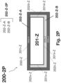
- FIGS. 2 I-P illustrate cross sectional depictions of nanofilm-encapsulated sulfide glass separator sheets in accordance with various embodiments of the present disclosure.
- FIG. 2 Q is a process flow diagram illustrating various process embodiments of making a nanofilm-encapsulated sulfide glass solid electrolyte structure in accordance with the present disclosure.
- FIGS. 3 A-E illustrate cross sectional and top down depictions of lithium metal layers and lithium metal surfaces.
- FIGS. 4 A-G illustrate apparatus and method for making a lithium metal layer having substantially unpassivated surfaces, in accordance with various embodiments of the present disclosure.
- FIGS. 4 H-J illustrate apparatus, methods and tools for making a lithium metal layer by evaporation and having substantially unpassivated surfaces, in accordance with various embodiments of the present disclosure.
- FIG. 4 K illustrates apparatus and process for making vacuum die extruded lithium metal layers in accordance with an embodiment of the present disclosure.
- FIGS. 5 A-B illustrate a lithium roll assembly cartridge according to one embodiment of the present disclosure.
- FIG. 6 A illustrates an apparatus and method for cleaning and treating an inorganic solid electrolyte layer, in accordance with an embodiment of the present disclosure.
- FIG. 6 B illustrates a cross sectional depiction of an inorganic solid electrolyte layer coated with a thin precursor film, in accordance with one embodiment of the present disclosure.
- FIG. 7 illustrates a cross sectional depiction of a solid-state laminate electrode assembly in accordance with one embodiment of the present disclosure.
- FIG. 8 A illustrates an apparatus and method for making a solid-state laminate electrode assembly in accordance with one embodiment of the present disclosure.
- FIG. 8 B-C illustrates apparatus, method and tool for making a solid-state laminate electrode assembly in accordance with one embodiment of the present disclosure.
- FIG. 8 D illustrates cross sectional depictions of solid-state laminate electrode assemblies in accordance with one embodiment of the present disclosure.
- FIG. 8 E illustrates an arrangement of a combination apparatus (or tool) suitable for thin film fabrication methods described herein, including ALD tool, a lithium thermal evaporation tool, and an Argon plasma ion etch tool for cleaning sulfide glass surfaces.
- FIG. 8 F is a process flow diagram illustrating methods for making solid-state laminate electrode assemblies in accordance with embodiments of the present disclosure.
- FIG. 9 illustrates a roll assembly cartridge containing a solid-state laminate electrode assembly according to one embodiment of the present disclosure.
- FIG. 10 illustrates a cross sectional depiction of a battery cell in accordance with one embodiment of the present disclosure.
- FIG. 11 illustrates a cross sectional depiction of a battery cell in accordance with one embodiment of the present disclosure.
- FIG. 12 illustrates a protected sulfide glass solid electrolyte sheet of this disclosure.
- FIG. 13 illustrates an electrode assembly of this disclosure.
- FIG. 14 illustrates an alternative embodiment of a protected sulfide glass solid electrolyte sheet of this disclosure.
- FIG. 15 illustrates an alternative embodiment of a protected sulfide glass solid electrolyte sheet of this disclosure.
- FIG. 16 illustrates an alternative embodiment of an electrode assembly of this disclosure.
- FIG. 17 illustrates an alternative embodiment of a protected sulfide glass solid electrolyte sheet of this disclosure.
- FIG. 18 illustrates an alternative embodiment of an electrode assembly of this disclosure.
- FIG. 19 illustrates a battery cell in accordance with various embodiments of this disclosure.
- FIG. 20 illustrates a cross-sectional depiction of a protected sulfide solid electrolyte glass sheet in accordance with embodiments of the present disclosure.
- FIG. 21 illustrates a method of making a converted compound layer according to various embodiments of the present disclosure.
- the present disclosure describes solid-state laminate electrode assemblies and various methods for making the solid-state laminate electrode assemblies.
- the solid-state laminate electrode assembly comprises a lithium metal layer reactively bonded to a lithium ion conducting sulfide glass layer.
- the reactive bond is sufficiently complete that it forms a continuous solid electrolyte interphase (SET) at the boundary between the layers.
- the lithium metal layer should have a major surface, which, just prior to bonding (e.g., by laminating), is in a highly reactive state (i.e., it is substantially unpassivated).
- the method involves making a pristine lithium metal layer having a substantially unpassivated first major surface, and therefore highly reactive, and maintaining the highly reactive surface in its substantially unpassivated state until it has been reactively bonded with the sulfide glass layer.
- the present disclosure provides methods for making a solid-state laminate electrode assembly. Such a method includes:
- the reactive bonding operation is a lamination process performed in a chamber filled with a dry gas (e.g., dry Argon).
- a dry gas e.g., dry Argon
- the laminating operation involves applying both heat and pressure.
- the inert protective material layer removably covering one or both of the sulfide glass first major surface and the substantially unpassivated lithium metal surface is a liquid phase protective fluid.
- the liquid phase protective fluid removably covering the lithium metal surface is removed just prior to the reactive bonding operation (e.g., the period of time between removing the liquid phase protective fluid and reactive bonding is less than 10 seconds, and preferably less than 5 seconds, and even more preferably less than 2 seconds).
- an SEI may be engineered by coating a first major surface of the sulfide glass with a thin precursor film that reacts with lithium metal during the bonding operation to form a solid electrolyte interphase.
- the sulfide glass surface may be treated under a Nitrogen containing plasma to incorporate Nitrogen into the surface of the glass, and then forming a lithium nitride.
- the method further comprises the operation of cleaning the first major surface of the sulfide glass under an Argon plasma, by ion etching, this operation performed after removing the inert protective material layer off of the sulfide glass but before reactive bonding.
- the method further comprises the operation of treating the clean sulfide glass first major surface to modify its surface composition.
- the surface composition is modified by placing the clean first major surface of the sulfide glass under a Nitrogen containing plasma, wherein the treatment modifies the surface composition of the sulfide glass by introducing Nitrogen into/onto the surface.
- the method further comprises the operation of coating the clean sulfide glass first major surface with a thin precursor film having a composition that will react in direct contact with lithium metal.
- the thin precursor film is formed by condensing between 1 to 5 monolayers of a Halogen (e.g., iodine) or Interhalogen or Nitrogen onto the clean sulfide glass surface; wherein the iodine monolayers leads to reactive wetting during the reactive bonding operation.
- a Halogen e.g., iodine
- the method further comprises coating the clean sulfide glass surface to form a precursor film that reacts with lithium during the reactive bonding operation to form a solid electrolyte interphase between the lithium metal layer and sulfide glass layer.
- the inert protective material layer removably covering one or both of the sulfide glass first major surface and the substantially unpassivated lithium metal surface is a liquid phase protective fluid.
- the present disclosure provides methods for making a pristine lithium metal layer having a substantially unpassivated first major surface, as defined herein below.
- a current collector e.g., a copper foil
- the pristine lithium metal layer is in the form of a long continuous roll of lithium that is immersed in liquid phase protective fluid for storage and/or downstream processing of battery cells (e.g., the pristine lithium metal layer at least 100 cm in length).
- the method involves making the pristine lithium metal layer in a protective inert fluid, and maintaining the pristine lithium metal layer in protective fluid (e.g., protective liquid) to prevent directly exposing the surface to the ambient gaseous atmosphere (including dry Argon of a glove box or dry Air of a dry room).
- protective fluid e.g., protective liquid
- the protective fluid is an inert liquid or the vapor of an inert liquid (i.e., protective vapor).
- the lithium metal layer is in the form of a long continuous ribbon (e.g., more than 50 cm in length).
- the method for making the substantially unpassivated lithium metal surface includes an extrusion operation that produces a fresh substantially unpassivated lithium first major surface inside or surrounded by protective fluid (e.g., a protective and super dry liquid hydrocarbon).
- protective fluid e.g., a protective and super dry liquid hydrocarbon.
- super dry it is meant that the amount of moisture in the liquid hydrocarbon is not greater than 0.1 ppm.
- the pristine lithium metal layer and its substantially unpassivated surface is extruded directly into liquid phase protective fluid (i.e., protective liquid), and then optionally the method further includes winding the lithium metal layer into a long continuous roll while it is immersed in liquid phase protective fluid.
- the extrusion operation is die extrusion of lithium ingot directly into a super dry liquid hydrocarbon bath.
- the extrusion operation is a roller extrusion wherein the lithium metal foil thickness is roll reduced in protective liquid, and in the process forms fresh lithium substantially unpassivated lithium metal surfaces, wherein the area of the fresh surfaces so formed is proportional to the reduction in thickness of the lithium layer.
- multiple roll reduction operations are performed (e.g., 2, 3, 4 or 5 or more) in order to produce the desired thickness and to perfect the substantially unpassivated surface (e.g., a pristine surface).
- the stock foil used for the roll reduction process has been pre-passivated, to improve reproducibility of the starting surface condition.
- a lithium ingot is die extruded directly into protective fluid to form a pristine lithium metal layer, and then that layer is immediately roll reduced in protective fluid to the desired thickness, and throughout the process the substantially unpassivated lithium metal surface remains covered or immersed in liquid phase protective fluid.
- the pristine lithium metal as formed may then be wound into a long continuous roll of pristine lithium metal, the winding performed in protective fluid (e.g., the winding performed inside liquid phase protective fluid).
- the substantially unpassivated lithium metal surfaces are stored in a canister of protective liquid, or they are formed and immediately transferred into the canister, without exposing the surfaces to the ambient gaseous environment.
- the present disclosure provides a standalone electrochemical material laminate structure for maintaining a major surface of a battery active material layer in a substantially unpassivated and/or substantially uncontaminated condition during handling, storage and/or battery cell fabrication.
- the battery active material layer reacts with water and/or Oxygen, and even under fairly dry ambient conditions, such as that of a dry air room or a dry Argon filled glove box the battery material surfaces chemically degrade or passivate rather quickly.
- the laminate structures of the present disclosure protect the battery material surfaces by encapsulating them underneath an inert removable layer, which inhibits moisture and/or oxygen from reaching the surfaces.
- the standalone electrochemical material laminate structures of the present disclosure are particularly useful for making, storing and transporting moisture sensitive battery active material layers, and for making downstream battery cells and laminate electrode assemblies from those material layers.
- a standalone electrochemical material laminate structure may be composed of two or more continuous material layers, wherein at least one of the material layers (i.e., a first material layer) is a “battery active solid material” having a clean (i.e., substantially uncontaminated) and/or substantially unpassivated surface, and another material layer (i.e., a second material layer) is a “protective material” that is inert, not battery active, and removably covers, in direct contact, a first major surface of the battery active material.
- a first material layer is a “battery active solid material” having a clean (i.e., substantially uncontaminated) and/or substantially unpassivated surface
- another material layer i.e., a second material layer
- a “protective material” that is inert, not battery active, and removably covers, in direct contact, a first major surface of the battery active material.
- battery active it generally means that the material is active in an electrochemical sense and useful in a battery cell (i.e., it is either an electro-active material or an electrolyte material).
- battery active solid material layer means either a solid alkali metal or an inorganic solid electrolyte having utility as a continuous solid layer in a battery cell (e.g., a lithium metal layer or a Li-ion conducting sulfide glass sheet, respectively).
- the protective material layer is inert and not battery active.
- inert it means that the referenced inert material does not chemically react in contact with the battery active solid material on which it is intended to protect.
- the protective material layer as “not battery active,” it is meant that the material layer is not useful in a battery cell, and is furthermore not intended for use in a battery cell, and not active in a battery/electrochemical sense (i.e., not an electroactive material or alkali metal ion conductor).
- the protective material layer i) provides an encapsulating barrier against direct touching exposure between the first major surface of the battery active material layer and the ambient gaseous atmosphere or contaminants in a vacuum chamber about the layer; ii) is inert in direct contact with the first major surface; and iii) is readily removed without physically damaging the surface.
- the protective material layer is an inert liquid (e.g., a super dry hydrocarbon liquid) that encapsulates the surface on which it is applied, and may be evaporatively removed in the absence of solid to solid touching contact
- the battery active material layer is an electroactive alkali metal layer having a substantially unpassivated first major surface (e.g., a pristine lithium metal layer), and in such embodiments the standalone electrochemical material laminate structure is generally referred to herein as a standalone alkali metal laminate structure; e.g., a standalone lithium metal laminate structure.
- the battery active material layer is an inorganic solid electrolyte layer having a substantially uncontaminated first major surface (e.g., a lithium ion conducting sulfide glass sheet), and in such embodiments the standalone electrochemical material laminate structure is generally referred to herein as a standalone solid electrolyte laminate structure; e.g., a standalone sulfide glass laminate structure.
- standalone when referring to an electrochemical material laminate structure, such as a standalone alkali metal laminate structure or a standalone solid electrolyte laminate structure, it is meant to emphasis that the battery active material layer in the standalone laminate is a discrete battery active material layer that has not yet been combined or coupled with a second battery active material layer, or yet been placed in a battery cell.
- the present disclosure provides methods for making lithium metal layers having substantially unpassivated surfaces and preventing passivation by encapsulating them with inert liquid.
- the methods include making a lithium metal foil having substantially unpassivated surfaces by die extruding a lithium ingot into a bath of super dry liquid hydrocarbons.
- the as made substantially unpassivated lithium metal foil may be further reduced in thickness by roller reduction and applying hydrocarbon liquid onto the freshly formed surfaces to ensure that they remain substantially unpassivated.
- a pre-passivated lithium metal layer of thickness (t) may be roller reduced in a roller mill using multiple roll reduction operations while at all times maintaining liquid hydrocarbon on the freshly formed lithium metal layer surfaces.
- pre-passivated lithium metal e.g., passivated by exposure to CO 2
- reproducibility is improved because the initial surface condition of the lithium is itself reproducible, as opposed to using lithium metal that is passivated in a less or uncontrolled fashion.
- the area of freshly formed lithium is proportional to the decrease in thickness of the layer.
- the present disclosure provides methods for making inorganic lithium ion conducting sulfide glass sheets having substantially uncontaminated surfaces, and for preventing hydrolysis of those surfaces by encapsulating them underneath an inert super dry hydrocarbon fluid (e.g., liquid).
- an inert super dry hydrocarbon fluid e.g., liquid
- the inorganic sulfide glass sheets are cleaned by ion etching in an Ar plasma to etch away any contaminated surface(s), and then substantially immediately after the ion etching operation, the cleaned sulfide glass sheet may be immersed in a liquid hydrocarbon bath, or the clean surface encapsulated by a protective liquid layer, as described above.
- the surface composition of the sulfide glass may be modified during or immediately after cleaning by using an Argon/Nitrogen plasma mixture for incorporating Nitrogen into the surface of the sulfide glass sheet, or the surfaces may be treated sequentially, using a first ion etch in argon plasma, followed by a second treatment in a nitrogen containing plasma (e.g., pure Nitrogen or an Argon/Nitrogen mixture).
- a nitrogen containing plasma e.g., pure Nitrogen or an Argon/Nitrogen mixture
- the present disclosure provides methods of making a strongly adhered fully solid-state inorganic laminate electrode assembly having a substantially contaminate free inorganic interface.
- the method includes providing a first battery active material as a component of a lithium metal laminate structure (e.g., a lithium metal layer having a first major surface which is substantially unpassivated and protected by an inert hydrocarbon liquid layer); providing a second battery active material layer as a component of an inorganic solid electrolyte laminate structure (e.g., a lithium ion conducting sulfide glass sheet having a clean first major surface that is devoid of hydrolysis reaction products and protected by an inert hydrocarbon liquid layer); removing the inert hydrocarbon liquid layers; and then, substantially immediately thereafter, reactively bonding the substantially unpassivated lithium metal surface to the clean inorganic sulfide glass surface, to form a strongly adhered laminate having a clean inorganic interface with a low area resistance (preferably, less than 50 ⁇ -cm 2 ).
- a low area resistance
- an improved laminate interface is formed by laminating the fluid protected lithium metal surface to a solid electrolyte sheet using techniques whereby the fluid is removed substantially immediately prior to, or during, the laminating operation, as the solid electrolyte comes into direct contact with the fluid and the lithium metal layer.
- the laminating operation effects a three phase boundary of lithium metal layer, solid electrolyte, and protective fluid, and causes the fluid to be removed from the surface substantially instantaneously as the solid electrolyte layer reactively adheres to the pristine lithium metal layer surface.
- the present disclosure relates to methods and reagents to form a thin, dense and lithium ion conductive layer between a lithium metal layer and an inorganic solid electrolyte layer (e.g., a lithium ion conducting sulfide glass).
- the layer is sometimes referred to herein as a solid electrolyte interphase (SEI) as it is formed by reacting a first major surface of the lithium metal layer with a coating on the glass surface that allows for the glass electrolyte to be optimized for high ionic conductivity and processability, regardless of its chemical compatibility with lithium metal.
- SEI solid electrolyte interphase
- the present disclosure provides methods of making battery cells by combining the fully solid-state inorganic laminate electrode assembly of the present disclosure with a positive electrode (e.g., a lithium ion intercalating positive electrode).
- a positive electrode e.g., a lithium ion intercalating positive electrode
- the protective fluid is selected from a group of saturated hydrocarbons with the number of carbon atoms from 5 to 15.
- the protective fluid is isododecane.
- the protective fluids may be a combination of these various fluids.
- the fluids generally contain no dissolved or dispersed chemicals (e.g., salts, lubricants and/or greases) that would coat the surface of the lithium metal layer or solid electrolyte layer with a solid film or residue. Accordingly the protective fluid is devoid of any dissolved salts (e.g., lithium salts).
- Suitable protective fluids are chemically inert to Li metal or Li alloys and contain less than 0.1 ppm of moisture, less than 1 ppm of moisture, less than 5 ppm of moisture, less than 10 ppm of moisture.
- the protective fluid is chosen to be non-reactive with the glass coating.
- n-Octane C 8 H 18 BP 125° C.
- n-Decane C 10 H 22 BP 174° C., Vapor Pressure: 2.7 mmHg at 20° C.
- n-Dodecane C 12 H 26 BP 216° C., Vapor Pressure: 0.14 mmHg at 25° C.
- Isodecane C 10 H 22 BP 167° C. Vapor Pressure: 2.3 mmHg at 25° C.
- Cycloalkadienes C 6 -C 8 , C n H 2n ⁇ 4 1,3-Cyclohexadiene C 6 H 8 BP 80° C., Vapor Pressure: 56 mmHg at 25° C.
- the protective inert liquid layer is devoid of dissolved and/or dispersed chemicals (e.g., salts, lubricants and/or greases) that would coat the surface of the battery active material layer with a solid film or leave behind a sticky residue. Accordingly, the protective inert liquid layer is generally devoid of dissolved salts (e.g., lithium salts, or more generally alkali metal salts).
- dissolved salts e.g., lithium salts, or more generally alkali metal salts.
- the liquid hydrocarbon(s) should have a very low concentration of moisture.
- concentration of moisture in the inert liquid hydrocarbon layer is less than 10 ppm of water, more preferably less than 5 ppm of water, even more preferably less than 1 ppm of water, and yet even more preferably less than 0.1 ppm of water (i.e., super dry).
- the inert liquid is actively dried in the presence of sacrificial alkali metal surfaces (e.g., pieces/chips of lithium or sodium metal) that getter oxygen, water and nitrogen impurities.
- the liquid hydrocarbons may be passed through a drying a chamber in order to maintain very low moisture levels.
- the drying chamber may contain drying agents and oxygen getters.
- drying agents for liquid hydrocarbons include molecular sieves (3 A, 4 A, or 5 A depending on the hydrocarbon type), magnesium oxide, zinc chloride, calcium sulfate, calcium chloride, calcium hydride, and alumina (neutral or basic).
- the cumulative area of the sacrificial alkali metal surfaces in direct contact with the inert liquid is greater than the first major surface of the battery active material layer on which the inert liquid covers in direct contact, for instance when the battery active material layer is disposed in a protective liquid bath, as described in more detail herein below.
- the present disclosure provides methods for making a solid-state laminate electrode assembly.
- the solid-state laminate electrode assembly is a lithium metal layer reactively bonded with a lithium ion conducting sulfide glass layer.
- process flow diagram 5 for making a solid-state laminate electrode assembly in accordance with various embodiments of the present disclosure.
- the process includes initial operations 10 and 20 , for making or providing a first and a second standalone electrochemical material laminate structure, respectively.
- first and second electrochemical material laminate structures are not the same.
- the term electrochemical material laminate structure means a laminate of two or more continuous material layers, wherein at least one of the material layers (i.e., a first material layer) is a “battery active solid material layer” having a clean (i.e., substantially uncontaminated) and/or substantially unpassivated first major surface, and another material layer (i.e., a second material layer) is a “protective material layer” that is inert, not battery active, and removably covers, in direct intimate contact, the first major surface of the battery active material layer.
- the protective material layer is a liquid phase layer of a protective fluid, such as a super dry hydrocarbon liquid that is spread out evenly over the first major surface of the battery active material layer.
- the battery active material layer is highly reactive with water and/or oxygen, and its surfaces chemically degrade or passivate rather quickly, even under dry or vacuum conditions, including that of a dry air room suited for handling lithium metal (e.g., having a dew point between ⁇ 20 to ⁇ 40′C) or a dry Argon filled glove box (e.g., having a low moisture and oxygen content of between 1 to 5 ppm).
- the electrochemical laminate structure is the laminate that is used to shield a battery active material layer against adverse reactions with the environment in which it (the battery active material layer) is made, processed and/or stored.
- solid battery active material layer it is meant either a solid alkali metal layer (e.g., typically embodied herein as a lithium metal layer) or an inorganic solid electrolyte layer (e.g., typically embodied herein as a lithium ion conducting sulfide glass).
- the laminate structure is referred to generally as an alkali metal laminate structure (or more specifically in this case as a lithium metal laminate structure)
- the laminate structure is referred generally as a solid electrolyte laminate structure (or more specifically in this case as a sulfide glass laminate structure).
- standalone when referring to an electrochemical material laminate structure, such as a standalone alkali metal laminate structure or a standalone solid electrolyte laminate structure, it is meant to emphasis that the battery active material layer in the standalone laminate is a discrete battery active material layer that has not yet been combined or coupled with a second battery active material layer, or yet been placed in a battery cell.
- standalone lithium laminate structures are absent of an electrolyte and standalone sulfide glass solid electrolyte laminate structures are absent of battery electroactive materials.
- the first electrochemical material laminate structure, which is provided or made in process operation 10 is a standalone lithium metal laminate structure
- the second electrochemical material laminate structure, which is provided in process operation 20 is a standalone sulfide glass laminate structure.
- the liquid hydrocarbon employed herein as a protective material layer is selected, in part, on its ability to remain on the surface of the lithium metal or sulfide glass layer until such time that it is to be controllably removed; accordingly it cannot be allowed to evaporate off by happenstance.
- Processes for accelerating and controllably removing the protective liquid layer off of the battery active material layer are generally performed in a chamber designed for that purpose. Such processes include one or more of heating, vacuum suction, blowing a jet of dry inert gas, blowing a jet of high vapor pressure protective fluid followed by vacuum suction, as well as rinsing the surfaces progressively with protective fluids having progressively higher vapor pressures.
- the chamber or conduit through which the battery active material layers are translated may be filled with vapor phase protective fluid right up until the layers are combined for lamination, according to process operation 30 , wherein the layers are reactively bonded to each other.
- the glass first major surface may be processed and/or treated prior to laminating with lithium metal in order to engineer a solid electrolyte interphase (SEI) with improved electrochemical properties, or when the sulfide glass is not chemically compatible with lithium metal.
- SEI solid electrolyte interphase
- the sulfide glass may undergo cleaning process 24 A, exemplified by an ion etch treatment under an Ar plasma followed by surface treating process 24 B, wherein the cleaned glass surface may be coated with a thin lithium metal reactive precursor film or treated to modify the surface composition of the glass (e.g., by placing the glass first major surface under a Nitrogen containing plasma).
- the present disclosure provides a standalone electrochemical material laminate structure for maintaining a major surface of a battery active material layer in a substantially unpassivated and/or substantially uncontaminated condition during storage and/or battery cell component fabrication (e.g., fabrication of a fully solid-state laminate electrode assembly).
- the standalone electrochemical material laminate structure is composed of two or more continuous material layers, wherein at least one of the material layers (i.e., a first material layer) is a “battery active solid material layer” having a clean (i.e., substantially uncontaminated) and/or substantially unpassivated first major surface, and another material layer (i.e., a second material layer) is a “protective material layer” that is inert, not battery active, and removably covers, in direct contact, the first major surface of the battery active material layer.
- a first material layer is a “battery active solid material layer” having a clean (i.e., substantially uncontaminated) and/or substantially unpassivated first major surface
- another material layer i.e., a second material layer
- a “protective material layer” that is inert, not battery active, and removably covers, in direct contact, the first major surface of the battery active material layer.
- the battery active material layer is highly reactive with water and/or Oxygen, and its surfaces will chemically degrade or passivate rather quickly, even under fairly dry conditions of a dry Air room (e.g., having a dew point of ⁇ 20° C.) or a dry Argon filled glove box (e.g., having a low moisture and oxygen content of between 1 to 5 ppm).
- a dry Air room e.g., having a dew point of ⁇ 20° C.
- a dry Argon filled glove box e.g., having a low moisture and oxygen content of between 1 to 5 ppm.
- the protective material layer i) minimizes, and preferably prevents, direct touching exposure between the first major surface of the battery active material layer and the ambient gaseous atmosphere or vacuum environment about the layer (e.g., during handling, processing and/or storage); ii) is inert in direct contact with the first major surface; and iii) is readily removed without physically damaging the surface.
- the protective material layer is an inert liquid (e.g., a super dry hydrocarbon liquid) that encapsulates the surface on which it is applied, and may be evaporatively removed in the absence of solid to solid touching contact.
- the battery active material layer is an electroactive alkali metal layer having a substantially unpassivated first major surface (e.g., a pristine lithium metal layer), and in such embodiments the standalone electrochemical material laminate structure is generally referred to herein as a standalone alkali metal laminate structure; e.g., a standalone lithium metal laminate structure.
- the first major surface is pristine.
- the battery active material layer is an inorganic solid electrolyte layer (e.g., a lithium ion conducting sulfide glass sheet), and in such embodiments the standalone electrochemical material laminate structure is generally referred to herein as a standalone solid electrolyte laminate structure; e.g., a standalone sulfide glass laminate structure.
- the sulfide glass layer has a first major surface that is clean (i.e., substantially uncontaminated).
- the standalone electrochemical material laminate structure of the present disclosure can be constructed using a number of different architectures, some of which are described in more detail herein below
- FIGS. 2 A-D and FIGS. 2 E-H there are illustrated cross sectional depictions of standalone electrochemical material laminate structures in accordance with various embodiments of the present disclosure.
- the main differences between the structures shown in FIGS. 2 A-D and those shown FIGS. 2 E-H are the battery active material layer.
- the battery active material layer is lithium metal
- the electrochemical material laminate structure is a lithium metal laminate structure.
- the battery active material layer is a lithium ion conducting sulfide glass
- the electrochemical material laminate structure is an inorganic solid electrolyte laminate structure.
- the laminate structures may take on a variety of shared architectures and these architectures are now described with reference to a battery active material layer. Thereafter, details particular to the lithium metal layer and to the sulfide glass layer are provided.
- Structure 100 A/ 200 E is composed of: i) freestanding battery active material layer 101 / 201 having first and second major surfaces ( 101 i / 201 i and 101 ii / 201 ii ) and lengthwise edge surfaces ( 101 iii / 201 iii and 101 iv / 201 iv ); and ii) inert liquid layer 102 / 202 encapsulating the major surfaces and the lengthwise edge surfaces (e.g., a super dry liquid hydrocarbon layer).
- inert liquid layer 102 / 202 is a super dry hydrocarbon that fully wets out the first and second major opposing surfaces and lengthwise edge surfaces ( 101 i , 101 ii , 101 iii , and 101 iv as well as 201 i , 201 ii , 201 iii , and 201 iv ).
- Structure 100 B/ 200 F is composed of battery active material layer 101 / 201 and material backing layer 103 / 203 , which may be rigid or flexible.
- layer 103 / 203 is a substrate onto which the battery active material layer is formed, or it (the backing layer) may be applied to second major surface 101 ii / 201 ii after layer 101 / 201 has already been formed.
- Inert liquid layer 102 / 202 encapsulates first major surface 101 i / 201 i , and may additionally encapsulate its lengthwise edge surfaces, as shown.
- backing layer 103 extends beyond layer 101 / 201 , and the inert liquid wets out the lengthwise edges, as shown.
- backing layer 103 / 203 is electronically insulating, and used generally as a supporting layer 101 / 201 during handling, storage and processing (e.g., as an interleave to facilitate winding and unwinding).
- backing layer 103 may be an inert organic polymer (e.g., a polyethylene or polypropylene film).
- backing layer 103 when the battery active material layer is lithium metal layer 101 , backing layer 103 (flexible or rigid) may be electronically conductive, and thereon serve as a current collector in a battery cell.
- backing layer 103 may be a metal foil or mesh (e.g., copper), or it (backing layer 103 ) may be a thin copper film deposited on a polymer support layer (e.g., a polyester film).
- a polymer support layer e.g., a polyester film.
- FIG. 2 C and FIG. 2 G there is illustrated standalone electrochemical material layer structure 100 C/ 200 G, which, in accordance with various embodiments of the present disclosure has, what is termed herein, a wet-decal architecture, and for this reason structure 100 C/ 200 G is sometimes referred to herein more simply as a wet-decal or decal (e.g., Li-decal 100 C or sulfide glass decal 200 G).
- a wet-decal or decal e.g., Li-decal 100 C or sulfide glass decal 200 G.
- Laminate structure 100 C/ 200 G includes solid material release layer 104 / 204 covering but not touching battery active material layer surface 101 i / 201 i , and inert liquid layer 102 / 202 sandwiched there between, and encapsulating the surface on which it is applied ( 101 i / 201 i ).
- the inert liquid of layer 102 / 202 completely wets out surface 101 i / 201 i as well as the surface of release layer 104 / 204 , and this leads to the formation of a liquid bridge between the layers and an associated wet adhesive force that assists in maintaining the release layer on the battery active material during handling and processing.
- the degree of wettability may be determined by the contact angle ( ⁇ ). Accordingly, in various embodiments one criterion that may be used for selecting the protective liquid is based, in part, on its ability to fully wet out the battery active material surface on which it is disposed.
- the ability of the inert liquid to wet out both surface 101 i / 201 i and layer 104 / 204 is sufficient to spread the inert liquid layer evenly and intimately over surface 101 i / 201 i , to encapsulate it (the first major surfaces) and prevent the solid release layer from touching the battery active material.
- inert liquid layer 102 / 202 is thin enough to bring about a tight liquid bridge that is capable of maintaining the solid release on the battery active material during handling and processing.
- the average thickness of protective liquid layer 102 / 202 is not greater than 50 ⁇ m, or not greater than 25 ⁇ m, or not greater than 10 ⁇ m, or not greater than 5 ⁇ m, but sufficiently thick and uniform, nonetheless, to prevent contact between the release layer and surface 101 i (e.g., 50 ⁇ m>t>5 ⁇ m; or 5 ⁇ m>t>100 nm).
- inert liquid layer 102 / 202 has an average thickness in the range of 1 ⁇ m>t>100 nm; or in the range of 5 ⁇ m>t>1 ⁇ m; or in the range of 50 ⁇ m>t>5 ⁇ m.
- structure 100 C/ 200 C may have pockets or isolated locations that are not covered by protective liquid, and in such embodiments, it is especially important that release layer 104 / 204 is inert in contact with the battery active material.
- the wet decal architecture has a number of advantages, including: i) protecting surface 101 i / 102 i against physical damage during handling; ii) enhancing the utility and/or the ability to use medium to high vapor pressure inert liquids by lessening their effective evaporation rate; iii) improving protection against degradation of surface 101 i / 201 i against impurity molecules from the ambient atmosphere, as the release layer itself provides an additional barrier against contaminating molecules entering the protective liquid from the ambient atmosphere; iv) extending storage shelf life and service lifetimes due to the additional barrier properties and lower evaporation rate of the inert liquid layer, and finally v) the solid release layer may serve as an interleave for winding or stacking the laminate structures.
- the wet-decal architecture is sealed along its lengthwise edges by seal 113 / 213 , the seal providing an additional barrier against diffusion of impurity molecules from the ambient atmosphere seeping into the inert liquid layer and for minimizing evaporation of the inert liquid out from the laminate.
- the lengthwise edges are preferably also covered in direct contact with inert liquid.
- Lengthwise edge seal 113 / 213 may be made by heat and pressure applied between release layer 104 / 204 and backing layer 103 / 203 , which, in various wet-decal embodiments is simply a second release layer, similar or the same as layer 104 / 204 .
- an additional sealable backing layer may be placed behind the current collecting layer, for sealing the lengthwise edges.
- the edge seal may be broken by slicing with a sharp edge.
- the laminate thickness as measured from the second major surface of the battery active material layer 101 ii / 201 ii to the top surface of inert liquid layer 102 / 202 is no greater than 1 mm thick, and more typically no greater than 500 um thick.
- the laminate thickness (as defined above) is less than 500 um, and typically less than 200 um, and in some embodiments less than 100 um, or less than 50 um (e.g., between 5-100 um).
- the laminate thickness, as defined above does not include the thickness of the solid release layer, or backing layer when present.
- nanofilm-encapsulated sulfide glass solid electrolyte structure 200 - 2 I is composed of: i) sulfide glass solid electrolyte sheet 201 -Z having first and second major opposing surfaces ( 201 i -Z and 201 ii -Z) and opposing lengthwise edge surfaces 201 iii -Z/ 201 iv -Z; and ii) continuous inorganic nanofilm 202 -Z- 2 I which encapsulates the sulfide glass surfaces in direct contact.
- the opposing widthwise edge surfaces of sulfide sheet 201 -Z are also encapsulated by nanofilm 202 -Z- 2 I, and in such embodiments solid electrolyte structure 200 - 2 I is referred to herein as fully encapsulated (i.e., all surfaces of glass sheet 201 -Z are encapsulated by nanofilm 202 -Z- 2 ).
- the widthwise edges are not encapsulated, but may ultimately be shielded from the ambient atmosphere by a polymeric edge sealant (also not shown).
- encapsulating nanofilm 202 -Z- 2 I is a conformal pinhole free inorganic material layer that encapsulates, in direct contact, sulfide sheet surfaces 201 i -Z, 201 ii -Z, 201 iii -Z, and 201 iv -Z.
- the nanofilm is conformal so its surfaces adjacently align with the surfaces of the sulfide glass sheet on which it (the nanofilm) encapsulates.
- the nanofilm may be characterized similarly, as having first and second opposing major surfaces ( 202 i -Z and 202 ii -Z), opposing lengthwise edge surfaces 202 iii -Z and 202 iv -Z, and opposing widthwise edge surfaces, not shown.
- first and second opposing major surfaces 202 i -Z and 202 ii -Z
- opposing lengthwise edge surfaces 202 iii -Z and 202 iv -Z
- widthwise edge surfaces not shown.
- portion 202 a -Z and portion 202 b -Z refer to those portions of nanofilm 202 -Z- 2 I which are adjacent sulfide glass major surfaces 201 i -Z and 201 ii -Z, and portions of the nanofilm that encapsulate the edges of the sulfide glass sheet are referred to as edge encapsulating portions (e.g., lengthwise and widthwise nanofilm edge portions).
- thickness of nanofilm 202 -Z- 2 I is a tradeoff between enhancing the moisture barrier properties by using a thicker film, and ensuring that the nanofilm is sufficiently thin to be transparent or permeable to Li-ions, so to allow lithium ions to move across the solid electrolyte separator without effectuating a large area specific resistance (ASR); e.g., the ASR of the separator is no greater than 2001 ⁇ -cm 2 , when measured in a battery cell at room temperature, and preferably no greater than 100 ⁇ -cm 2 , and even more preferably no greater than 50 ⁇ -cm 2 .
- ASR area specific resistance
- Other considerations regarding nanofilm thickness include time of fabrication, reliability and yield.
- the first and second major portions of continuous nanofilm 202 -Z- 2 I each has substantially uniform thickness, typically in the range of 1 nm to 100 nm; e.g., [(1 nm ⁇ t ⁇ 5 nm); (5 nm ⁇ t ⁇ 10 nm); (10 nm ⁇ t ⁇ 30 nm); (30 nm ⁇ t ⁇ 50 nm); (50 nm ⁇ t ⁇ 10 nm)].
- the first and second major portions of nanofilm 202 -Z- 2 I (i.e., portion 202 a -Z and portion 202 b -Z) have uniform thickness of about 0.1 nm, 0.2 nm, 0.3 nm, 0.4 nm, 0.5 nm, 0.6 nm, 0.7 nm, 0.8 nm, 0.9 nm, 1 nm, 2 nm, 3 nm, 4 nm, 5 nm, 10 nm, or about 20 nm, or about 30 nm or about 40 nm or about 50 nm, or about 60 nm, or about 70 nm or about 80 nm or about 90 nm or about 100 nm).
- the nanofilm thickness it is meant the thickness of the nanofilm adjacent to the first and second major surfaces (i.e., the thickness of the nanofilm major portions 202 a -Z and 202 b -Z), as it is these surfaces which adjacently oppose the electrodes in a battery cell and therefore function electrochemically.
- the primary benefit provided by the edge portion of the nanofilm is to effect a moisture barrier and preferably enhance mechanical strength by blunting surface defects at or near the edge of the sulfide glass sheet, and so it (the edge portion of the nanofilm) should be sufficiently thick to provide a water impervious barrier (as described above).
- the thickness of its edge portion(s) are generally a function of the thickness of the nanofilm first and second major portions, and the edge portion thickness is generally similar to or greater than the thickness of the major nanofilm portions, because, as described in more detail below, the edge regions may be coated more than once when forming the continuous nanofilm. Accordingly, in various embodiments the nanofilm has an edge portion thickness that is substantially equal to the sum of the first and second nanofilm major portions 202 a -Z and 202 b -Z.
- nanofilm 202 -Z- 2 I is a continuous and conformal film having substantially uniform composition and first and second major portion thicknesses less than 1000 nm, and more typically less than 500 nm, and even more typically less than 200 nm.
- the nanofilm first and second major portion thicknesses are between 100 nm to 0.1 nm (e.g., between 10 nm to 1 nm).
- nanofilm first major portion 202 a -Z has a first composition and a first thickness
- nanofilm second major portion 202 b -Z has a second composition and a second thickness
- separator structures 200 - 2 J and 200 - 2 K are composed of sulfide glass solid electrolyte sheet 201 -Z encapsulated by continuous inorganic nanofilm 202 -Z- 2 I and 202 -Z- 2 J, respectively.
- the conformal nanofilm has a substantially uniform composition throughout and a thickness that is engineered to vary relative to the sulfide sheet surface on which it encapsulates.
- nanofilm thickness (T i ) refers to the substantially uniform nanofilm thickness adjacent sulfide sheet surface 201 i -Z (i.e., the thickness of nanofilm portion 202 a -Z), and it is significantly greater than nanofilm thickness (T ii ), which is the substantially uniform nanofilm thickness adjacent sulfide sheet surface 201 ii -Z (i.e., the thickness of nanofilm portion 202 b -Z)
- nanofilm thickness (T i ) refers to the substantially uniform nanofilm thickness adjacent sulfide sheet surface 201 i -Z (i.e., the thickness of nanofilm portion 202 a -Z)
- nanofilm thickness (T i ) refers to the substantially uniform nanofilm thickness adjacent sulfide sheet surface 201 i -Z (i.e., the thickness of nanofilm portion 202 a -Z)
- nanofilm thickness (T i ) refers to the substantially uniform nanofilm thickness adjacent sulfide sheet surface 201
- T ii thickness of nanofilm portion 202 b -Z
- Ti thickness of nanofilm portion 202 a -Z
- the absolute value of the difference between T i and T ii is between 1-5 nm, or between 5-10 nm, or between 10-20 nm, or between 20-50 nm, or between 50-100 nm.
- nanofilm-encapsulated sulfide glass solid electrolyte structure 200 - 2 L wherein sulfide glass solid electrolyte sheet 201 -Z is encapsulated by two continuous and conformal nanolayers (first nanolayer: 202 -Z-A) and (second nanolayer: 202 -Z-B), which, in combination, form continuous nanofilm 202 -Z- 2 L.
- Nanofilm 202 -Z- 2 L is configured to have an asymmetric architecture wherein the material composition of first nanolayer 202 -Z-A is different than the material composition of second nanolayer 202 -Z-B (i.e., the material composition of the first major nanofilm portion is different than the material composition of the second major nanofilm portion.
- the asymmetric nanofilm is a contiguous planar composite of first and second nanolayers, as opposed to a stacked multi-layer, which it is not as the nanolayers do not overlap on either major surface of the sulfide glass sheet. Rather the contiguity of the nanolayers is realized by an overlap at the edge portions of the glass sheet.
- FIGS. 2 M, 2 N, and 20 Additional nanofilm-encapsulated sulfide glass solid electrolyte structures having asymmetric architectures are shown in FIGS. 2 M, 2 N, and 20 , and described in more detail below.
- nanofilm-encapsulated sulfide glass solid electrolyte structure 200 - 2 M wherein sulfide glass solid electrolyte sheet 201 -Z is encapsulated by two continuous and conformal nanolayers (first nanolayer: 202 -Z-A) and (second nanolayer: 202 -Z-B), which, in combination, form continuous nanofilm 202 -Z- 2 M.
- Continuous nanolayer 202 -Z-B encapsulates in direct contact sulfide sheet first major surface 201 i -Z and sulfide sheet second major surface 201 i -Z.
- nanolayer 202 -Z-A encapsulates, in direct contact, nanolayer 202 -Z-B, in that region of nanofilm 202 -Z- 2 M which is adjacent to sulfide sheet 201 i -Z and does not encapsulate (and preferably does not contact) nanolayer 202 -Z-B in that region of the nanofilm adjacent to sulfide sheet surface 201 ii -Z.
- the material composition of first nanolayer 202 -Z-A is different than the material composition of second nanolayer 202 -Z-B.
- nanofilm-encapsulated sulfide glass solid electrolyte structure 200 - 2 N is similar to structure 200 - 2 M, as shown in FIG. 2 M , except that for structure 200 - 2 N, nano layer 202 -Z-B encapsulates nanolayer 202 -Z-A adjacent sulfide glass sheet surface 201 ii -Z, and nanolayer 202 -Z-B does not encapsulate (and preferably does not contact) nanolayer 202 -Z-A in that region of nanofilm 202 -Z- 2 N which is adjacent to sulfide sheet surface 201 i -Z.
- nanofilm-encapsulated sulfide glass solid electrolyte structure 200 - 2 O wherein sulfide glass solid electrolyte sheet 201 -Z is encapsulated by two continuous and conformal nanolayers (first nanolayer: 202 -Z-A) and (second nanolayer: 202 -Z-B), which, in combination, form continuous nanofilm 202 -Z- 2 O.
- Continuous nanolayer 202 -Z-A encapsulates in direct contact sulfide sheet first major surface 201 i -Z
- continuous nanolayer 202 -Z-B encapsulates, in direct contact, nanolayer 202 -Z-A, in that region of nanofilm 202 -Z- 20 which is adjacent to sulfide sheet 201 i -Z and encapsulates sulfide glass sheet surface 201 ii -Z in direct contact.
- Nanolayer 202 -Z-A does not encapsulate (and preferably does not contact) sulfide glass sheet surface 201 ii -Z.
- sulfide glass solid electrolyte sheet 201 -Z is encapsulated on glass sheet surface 201 ii -Z by nanolayer 202 -Z-B and is encapsulated on glass sheet surface 201 -Z by nanolayer 202 -Z-A, which also encapsulates nanolayer 202 -Z-B in that region of nano film 202 -Z-P which is adjacent to sulfide sheet surface 201 i -Z.
- sulfide glass solid electrolyte sheet 201 -Z is in the form of a ribbon (e.g., a long narrow sheet), having substantially parallel lengthwise edges and a thickness in the range of 5 um to 500 um, and more typically in the range of 10 um to 100 um, and even more typically in the range of 20-50 um.
- sulfide glass solid electrolyte sheet 201 -Z is in the form a discrete sheet, typically at least 1 cm wide and at least 2 cm long (e.g., at least 2 cm wide and at least 5 cm long). Particularly suitable sulfide glass solid electrolyte sheets are described in Applicant's pending patent applications U.S. patent application Ser. No.
- sulfide glass compositions described therein, and which are particularly useful as the sulfide glass composition for sheet 201 -Z include the following specific compositional examples: 0.7Li 2 S-0.29P 2 S 5 -0.01P 2 O 5 ; 0.7Li 2 S-0.28P 2 S 5 -0.02P 2 O 5 ; 0.7Li 2 S-0.27P 2 S 5 -0.03P 2 O 5 ; 0.7Li 2 S-0.26P 2 S 5 -0.04P 2 O 5 ; 0.7Li 2 S- 0.25P 2 S 5 -0.05P 2 O 5 ; 0.7Li 2 S-0.24P 2 S 5 -0.06P 2 O 5 ; 0.7Li 2 S-0.23P 2 S 5 -0.07P 2 O 5 ; 0.7Li 2 S 5 S-0.22P 2 S 5 -0.08P 2 O 5 ; 0.7Li 2 S-0.21P 2 S 5 -0.09P 2 O 5 ; 0.7Li 2
- silicon sulfide glass compositions include (1 ⁇ x)(0.5Li x S-0.5SiS x )-xLi 4 SiO 4 ; (1 ⁇ x)(0.6Li 2 S-0.4SiS 2 )-xLi 4 SiO 4 ; (1 ⁇ x)(0.5Li 2 S-0.5SiS 2 )-xLi 3 BO 3 ; (1 ⁇ x)(0.6Li 2 S-0.4SiS 2 )-xLi 3 BO 3 ; (1 ⁇ x)(0.5Li 2 S-0.5SiS 2 )-xLi 3 PO 4 ; (1 ⁇ x)(0.6Li 2 S-0.4SiS 2 )-xLi 3 PO 4 ; wherein x ranges from 0.01-0.2.
- sulfide based solid electrolyte sheet 201 -Z is a continuous vitreous sheet of sulfide glass (e.g., a monolithic sheet of sulfide glass); however, the present disclosure is not limited to nanofilm-encapsulated sulfide sheets of glass, but is meant to include other moisture sensitive sulfide based solid electrolyte layers, such as sheets composed of Li ion conducting sulfide ceramics and glass ceramics materials that benefit from an encapsulating-nanofilm, as described herein.
- moisture sensitive sulfide solid electrolyte sheet 201 -Z may be formed as a continuous sheet of sulfide glass that is subsequently crystallized or partially crystallized to form a ceramic or glass-ceramic sulfide sheet, or the ceramic/glass-ceramic sulfide sheet may be crystallized during glass sheet formation.
- sulfide based solid electrolyte layer 201 -Z may be a sulfide sheet formed by powder/particle compaction of Li ion conducting sulfide particles, including sulfide glass particles, sulfide glass-ceramic particles, polycrystalline sulfide ceramic particles and combinations thereof.
- Such materials include thio-Lisicons and LGPS type ionic conductors.
- Li 4 GeS 4 , Li 3 PS 4 , Li 4 SiS 4 , Li 3.25 Ge 0.25 P 0.75 S 4 , Li 4+x Si 1 ⁇ x Al x S 4 and Li 4+x Ge 1 ⁇ x Ga x S 4 , Li 4 ⁇ x Si 1 ⁇ x P x S 4 with x 0.6, Li 10 GeP 2 S 12 , Li 7 P 3 S 11 , Li 1 1AlP 2 S 12 , Li 10 SnP 2 S 12 .
- Sulfide based solid electrolyte structures made by particle compaction are described in U.S. Pat. Pub. No.: 20120177997; U.S. Pat. Pub.
- material layer compositions for the inorganic nanofilm is informed by the ability of that material, in dense ultra-thin form, to impart the desired functionality and/or advantage, such as moisture imperviousness, improved mechanical strength, enhanced chemical resistance to liquid electrolytes and oxidative stability in direct contact with cathode electroactive materials (e.g., intercalation materials having a voltage versus lithium metal that is greater than about 2.5V, or greater than about 3V or greater than about 3.5V).
- cathode electroactive materials e.g., intercalation materials having a voltage versus lithium metal that is greater than about 2.5V, or greater than about 3V or greater than about 3.5V.
- the material composition of the nanofilm or nanolayer is an insulator in bulk form, but is transparent or permeable to lithium ions as a nano layer.
- the nanofilm composition is a binary metal/semi-metal oxide or metal/semi-metal nitride; the binary nature generally simplifies nanofilm deposition, and so is preferable, however the present disclosure is not limited as such.
- compositions include the following and their combinations, aluminum oxide, boron oxide, zirconium oxide, yttrium oxide, hafnium oxide, and niobium oxide, tungsten oxide, titanium oxide, tantalum oxide, molybdenum oxide, zinc oxide, silicon oxide, vanadium oxide, chromium oxide, and silicon nitride, aluminum nitride, boron nitride, tungsten nitride, titanium nitride, chromium nitride, tantalum nitride, copper nitride, gallium nitride, indium nitride, tin nitride, zirconium nitride, niobium nitride, hafnium nitride, tantalum nitride.
- Multi-component nanofilm compositions are also contemplated herein, including oxides and nitrides of one or more metals/semi-metals, including aluminum, boron, zirconium, yttrium, hafnium, niobium, tungsten, titanium, tantalum, vanadium, chromium, molybdenum, zinc, and silicon.
- metals/semi-metals including aluminum, boron, zirconium, yttrium, hafnium, niobium, tungsten, titanium, tantalum, vanadium, chromium, molybdenum, zinc, and silicon.
- compositions may be combined with lithium to form lithium containing nanofilm compositions, including: lithium metal/semi-metal oxides, such as lithium aluminum oxide, lithium aluminum silicon oxide, lithium tantalum oxide and lithium niobium oxide; and lithium metal/semi-metal nitrides, such as lithium aluminum nitride, lithium silicon nitride, lithium boron nitride and combinations thereof.
- the nanofilm may be a moisture resistant sulfide, such as zinc sulfide.
- the nanofilm is a phosphorous oxide or oxynitride, such as a lithium phosphorous oxide (e.g., Li 3 PO 4 ) and lithium phosphorous oxynitride (i.e., a LiPON type nanofilm) with various stoichiometries, including LiPON.
- a lithium phosphorous oxide e.g., Li 3 PO 4
- lithium phosphorous oxynitride i.e., a LiPON type nanofilm
- the nanofilm is a phosphorous nitride (e.g., P 3 N 5 ), and in embodiments thereof may be a lithium phosphorous nitride devoid of oxygen; i.e., a ternary lithium phosphorous-nitride compound (e.g., LiPN 2 , Li 7 PN 4 ).
- a ternary lithium phosphorous-nitride compound e.g., LiPN 2 , Li 7 PN 4
- the nanofilm composition is that of an intrinsic Li ion conducting material.
- Intrinsic lithium ion conducting materials comprise lithium ions, and are generally understood in the art as lithium ion conducting solid electrolyte materials.
- An intrinsic Li ion conducting material is, itself, Li ion conductive, and typically has a room temperature conductivity of at least 10 ⁇ 7 S/cm, and its ability to conduct Li ions does not depend on a second material (e.g., a material layer onto which it is coated).
- Examples of intrinsic Li ion conducting material compositions which are suitable herein for use as the material of the nanofilm or that of a nanolayer include lithium phosphorous oxynitride (e.g., UPON), lithium titanates, lithium lanthanium titanates, lithium phosphate (e.g., Li 3 PO 4 ), lithium nitrate (LiNO 3 ), lithium silicates, lithium tantalum oxide (e.g., LiTaO 3 ), lithium aluminum oxide (e.g., LiAlO x ), lithium niobium oxide (e.g., LiNbO 3 ), lithium nitride (Li 3 N), lithium silicon aluminum oxide, lithium germanium aluminum oxide, and lithium germanium silicon aluminum oxide.
- nanofilm materials that are devoid of lithium are not intrinsic lithium ion conductors (e.g., metal oxides and metal nitrides devoid of lithium as well as phosphorous nitrides devoid of oxygen and lithium).
- the nanofilm composition is an inert binary metal oxide (e.g., alumina, hafnia, zirconia), and the thickness of the alumina nanofilm is in the range of 1 nm to 100 nm (e.g., about 1 nm, or about 2 nm or about 5 nm, or about 10 nm, or about 20 nm or about 30 nm or about 40 nm or about 50 nm or about 60 nm or about 70 nm or about 80 nm or about 90 nm or about 100 nm).
- alumina, hafnia, zirconia e.g., alumina, hafnia, zirconia
- the thickness of the alumina nanofilm is in the range of 1 nm to 100 nm (e.g., about 1 nm, or about 2 nm or about 5 nm, or about 10 nm, or about 20 nm or about 30 nm or about 40 n
- the inert metal oxide nanofilm fully encapsulates all surfaces of the sulfide glass sheet and has a thickness in the range of about 1 nm to 5 nm (e.g., about 1 nm, or about 2 nm, or about 3 nm, or about 4 nm, or about 5 nm.
- some amount of moisture barrier benefit is provided from an exceptionally thin fully encapsulating nanofilm, having thickness less than 1 nm (e.g., about 0.1 nm, or about 0.2 nm, or about 0.3 nm, or about 0.4 nm, or about 0.5 nm, or about 0.6 nm, or about 0.7 nm, or about 0.8 nm, or about 0.9 nm).
- the inert nanofilm may be employed to provide superior moisture barrier properties for protecting the sulfide glass during storage.
- thicker nanofilms generally provide an improved barrier; for instance, inert nanofilms with enhanced barrier properties are contemplated herein to have thickness in the range of 5 nm to 10 nm, or 10 nm to 20 nm, or 20-30 nm, or 30-40 nm, or 40-50 nm, or 50-60 nm or 60-70 nm, or 70-80 nm, or 80-90 nm or 90-100 nm.
- the nanofilm thickness adjacent the first and/or second major surfaces of the sulfide glass sheet is reduced or entirely removed (e.g., by plasma etching that portion of the nanofilm).
- the procedure to remove the nanofilm is performed just prior to depositing lithium metal onto the first major surface of the glass sheet (e.g., an inert binary metal oxide nanofilm (e.g., alumina) of thickness greater than 5 nm is entirely removed by Argon plasma etching prior to depositing lithium metal onto that surface).
- nanofilm 202 -Z- 2 L is configured to have an asymmetric architecture wherein the thickness and/or composition of the nanofilm first major portion is different than that of the nanofilm second major portion.
- the asymmetric architecture nanofilm is composed of two nanolayers: i) first nanolayer 202 -Z-A, which is an inert material layer having a thickness and composition that provides a moisture barrier and a low resistance interface in direct contact with lithium metal (e.g., the ASR of the solid electrolyte structure is less than 50 ⁇ -cm 2 , and preferably less than 25 ⁇ -cm 2 ; and ii) second nanolayer 202 -Z-B having thickness and composition suitable for it to serve as a moisture barrier and to provide an inert surface, which, when configured in a battery cell, opposing the cathode, is chemically compatible in direct contact with cathode electroactive material having an electrochemical potential of 3 Volts or greater versus lithium metal, and therewith prevents oxidation of the sulfide glass and/or prevents dissolution of sulfide glass material into the liquid electrolyte of the battery cell.
- first nanolayer 202 -Z-A which is an inert material
- first nanolayer 202 -Z-A is an inert metal nitride and second nanolayer 202 -Z-B is an inert metal oxide (e.g., a binary metal nitride and a binary metal oxide).
- inert metal nitride nanolayer 202 -Z-A is devoid of lithium metal (e.g., silicon nitride), and reactively converts to a lithiated composition when contacted with lithium metal during fabrication of a solid-state laminate electrode assembly, as described in more detail herein below.
- silicon nitride e.g., SiN, Si 3 N 4 , SiN
- silicon nitride nanolayer 202 -Z-A thickness of first major portion 202 a -Z of silicon nitride nanolayer 202 -Z-A is in the range of 1 to 100 nm (e.g., in the range of 1 nm to 10 nm).
- second nanolayer 202 -Z-B is an inert metal oxide such as aluminum oxide, zirconium oxide, and niobium oxide, with thickness in the range of 0.1 nm to 100 nm.
- the thickness of inert metal oxide nanolayer 202 -Z-B is in the range of 0.1 nm to 1 nm, or in the range of 1 nm to 10 nm.
- first nanolayer 202 -Z-A is a phosphorous nitride devoid of oxygen (e.g., P 3 N 5 ) that reactively lithiates in direct contact with lithium metal (e.g., upon lithium evaporation), to form a lithiated phosphorous nitride devoid of oxygen (e.g., LiPN 2 , Li 7 PN 4 , or a combination thereof).
- thickness of first major portion 202 a -Z of the P 3 N nanolayer 202 -Z-A is in the range of 1 to 100 nm (e.g., in the range of 1 nm to 10 nm).
- all surfaces of the sulfide glass solid electrolyte sheet 201 -Z are encapsulated in directed contact by the nanofilm.
- the continuous encapsulating nanofilm and its associated nanolayers are deposited/coated onto the surfaces of the sulfide glass sheet via the technique known as atomic layer deposition (ALD), including PEALD (plasma enhanced atomic layer deposition).
- ALD is a vapor phase deposition process, and generally consists of multiple coatings of chemical precursors that react with each other, and the sulfide sheet, to form a monolayer on the sheet surface. Forming the nanofilm using an ALD process allows for precise and accurate control of thickness and conformality, which is an attribute that allows the continuous nanofilm to form and encapsulate the edge and corner surfaces of the sulfide solid electrolyte sheet.
- the sulfide sheet takes the form of a continuous web (e.g., a continuous web of Li ion conducting vitreous sulfide glass)
- ALD techniques for continuous roll-to-roll deposition may be used, and are described in U.S. Pat. No. 9,598,769 entitled “Method and System for Continuous Atomic Layer Deposition;” U.S. Pat. No. 8,304,019 entitled “Roll-to-Roll Atomic Layer Deposition Method and System;” U.S. Pat. Pub. No.; 2007/0281089 entitled “Systems and Methods for Roll-to-Roll Atomic Layer Deposition on Continuously Fed Objects;” U.S. Pat. Pub.
- the methods include an initial operation (operation 1) of providing (e.g., making) a sulfide glass solid electrolyte sheet.
- the sheet is a strip of sulfide glass having a length to width aspect ratio of at least 2, or at least 3 or at least 4 or at least 5 or at least 10.
- the sulfide sheet of glass is provided as a web.
- organic residue is removed from the surfaces of the glass sheet by any suitable technique, for example by plasma etching, such as Argon plasma etching.
- the encapsulating-nanofilm is deposited via atomic layer deposition (ALD) onto the sulfide glass sheet, and the operations for making the nanofilm vary depending on the final architecture of the nanofilm-encapsulated sulfide solid electrolyte structure, and in particular the construction of the nanofilm.
- ALD atomic layer deposition
- the deposition of the nanofilm takes place in two operations.
- the third operation involves depositing a first nanolayer via ALD onto the first major surface of the sulfide glass sheet as well as the peripheral edge surfaces of the glass.
- the fourth operation involves depositing a second nanolayer via ALD onto the second major surface of the sulfide glass sheet, and the peripheral edge portions of the first nanolayer.
- process A may yield a number of different nanofilm architectures, and three embodiments are illustrated in the process flow diagram, Solid electrolyte structure 2 P 1 is formed when the second nanolayer has the same composition and thickness as the first nanolayer (solid electrolyte structure 2 Q 1 is similar solid electrolyte structure 200 - 2 I shown in FIG. 2 I ).
- Solid electrolyte structure 2 Q 2 is formed when the second nanolayer has a different composition than that of the first nanolayer, and is similar to solid electrolyte structure 200 - 2 L, shown in FIG. 2 L .
- Solid electrolyte structure 2 Q 3 is formed when the second nanolayer has the same composition as the first nanolayer, but a different thickness (solid electrolyte structure 2 P 3 is similar to solid electrolyte structure 200 - 2 J or 200 - 2 K, as shown in FIGS. 2 J and 2 K respectively.
- the third and fourth operations involve depositing a first and second nanolayer via ALD onto the first and second major surfaces of the sulfide glass sheet, respectively.
- the first and second nanolayers also providing encapsulation of the peripheral glass edge surfaces.
- the fifth operation (operation 5b) for process B involves depositing a third nanolayer that encapsulates the major surface of the first or the second nanolayer, wherein the third nanolayer has a different composition than that of the first and second nanolayer.
- the solid electrolyte structure 2 Q 4 thus formed is similar to solid electrolyte structures 200 - 2 M and 200 - 2 N, as shown in FIGS. 2 M and 2 N , respectively.
- the third operation (operation 3c) involves depositing a first nanolayer via ALD onto the first major surface of the sulfide glass sheet and the peripheral edge surfaces.
- operation 4c which involves depositing a second nanolayer via ALD onto the second major surface of the sulfide glass sheet, and the peripheral edge portions of the first nanolayer, and further wherein the second nanolayer has a different composition than that of the first nanolayer.
- operation 5c which involves depositing a third nanolayer via ALD onto the first nanolayer, wherein the third nanolayer has the same composition as that of the second nanolayer.
- solid electrolyte structure 2 Q 5 thus formed is similar to solid structures 200 - 2 O and 200 - 2 P, as shown in FIGS. 20 and 2 P , respectively.
- one function of protective material layer 102 / 202 is to removably cover and protect (e.g., encapsulate) at least the first major surface of the battery active material layer, and thereon provide a degree of protection against facile degradation caused by direct exposure of the lithium metal layer or sulfide glass layer to ambient gaseous atmospheres during handling, processing and/or storage.
- the layer i) covers the first surface of the battery active material in a manner that sufficiently protects the surface against chemical attack: ii) remains on the first surface during handling and storage; and iii) can be controllably removed without damaging the battery active material layer.
- controllably remove or “controllably removed” when referring to the protective material layer it is meant that the laminate structure is engineered to facilitate removal of the protective material layer in a controlled fashion, and is otherwise not easily removed (e.g., by happenstance, such as incidental evaporation during handling and processing of downstream components). Accordingly, the chemical make-up and physical properties of the protective material layer is properly selected to enable its controlled removal without damaging the battery active material layer, and the laminate structure engineered to ensure that the inert material layer stays intact as a protective layer for the desired time frame.
- protective material layer 102 / 202 is an inert liquid that intimately covers and spans substantially the first major surface of the battery active material layer (i.e., it is a continuous inert liquid layer).
- the composition of the inert liquid is selected, in part, based on it having a lower surface energy than the battery active material layer surface, and therefore capable of wetting out the battery active first major surface, and, thus, intimately covering it in direct contact, the liquid flowing and spreading out evenly to span substantially the entire surface (i.e., encapsulate the surface); e.g., encapsulate the first major surface.
- inert liquid layer 102 / 202 readily wets the first major surface of the battery active material layer.
- the wetting angle ( ⁇ ) that the inert liquid makes in contact with the battery active material layer is less than 90° (e.g., 0:5 ⁇ 90°), preferably less than 60°, more preferably less than 30°, even more preferably ⁇ is less than 10°, and yet even more preferably about 0°.
- the ability of the inert liquid layer to wet the battery active material layer surface is sufficient to encapsulate the one or more surfaces that it covers in direct contact.
- the thickness of inert liquid layer 102 / 202 is less than 1 mm.
- the thickness of the continuous inert liquid layer is in the range of 500 to 1000 um; or in the range of 200 to 500 um; or in the range of 100 to 200 um; or in the range of 50 to 100 um; or in the range of 20-50 um; or in the range of 10-20 um or in the range of 5-10 um; or in the range of 1-5 um: or, in some embodiments, it is contemplated that it may be less than 1 um.
- the inert liquid in order to retain inert liquid layer 102 / 202 on the surface of the battery active material layer during handling and processing, and controllably remove it (the inert liquid layer) without imparting damage or leaving behind a chemical residue, the inert liquid is selected based on a combination of its vapor pressure and boiling point.
- the inert liquid of the protective material layer is selected, in part, based on having a room temperature vapor pressure in the range of 0.1-10 mmHg (e.g., 0.1-1 mmHg), and/or based, in part, on having a boiling temperature in the range of 100-200° C.
- the inert liquid of protective material layer 102 / 202 is selected based on having a sufficiently low vapor pressure at room temperature (e.g., less than 10 mmHg, or less than 1 mmHg).
- the inert liquid of protective material layer 102 / 202 is selected based on having a sufficiently high boiling point temperature (e.g., greater than 100° C., or greater than 150° C. or greater than 200° C.).
- the inert liquid of protective material layer 102 / 202 is selected based on having a room temperature vapor pressure that is less than 10 mmHg and a boiling point temperature greater than 100° C.
- protective material layer 102 / 202 is composed of one or more inert hydrocarbon liquids (e.g., isododecane).
- Particularly suitable hydrocarbon liquids for use as a protective material layer are saturated hydrocarbons (e.g., having a number of carbon atoms per molecule ranging from 5 to 15).
- the inert hydrocarbon liquid is a saturated hydrocarbon liquid.
- the protective inert liquid saturated hydrocarbon is a straight chain alkane (typically having between 5 and 15 carbon atoms per molecule), such as n-Pentane, n-Hexane, n-Heptane, n-Octane, n-Nonane, n-Decane, n-Undecane, n-Dodecane.
- the protective inert liquid saturated hydrocarbon is a branched chain alkane (typically having 5 to 15 carbon atoms per molecules), such as isopentane, isohexane, isoheptane, isooctane, tetraethylmethane, isodecane, 3-methyldecane, isododecane.
- the protective inert liquid saturated hydrocarbon is a cycloalkane, such as cyclohexane, and cycloheptane, cyclooctane.
- the protective inert liquid hydrocarbon is an unsaturated acyclic hydrocarbon (e.g., C n H 2(n ⁇ m ⁇ 1) wherein n is the number of carbon atoms and m is the number of double bonds), such as alkenes (e.g., 1-Hexane, 1-Octane, 1-Nonene, 1-Docene, 1-Undecene, 1-Dodecene, or Alkadienes (e.g., 1,5-Hexadiene; 2,4-Hexadiene; 1,6-Heptadiene; 1,7-Octadiene; 1,8-Nonadiene; 1,9-Decadiene; 1,10-Undecadiene; and 1,11-Dodecadiene.
- alkenes e.g., 1-Hexane, 1-Octane, 1-Nonene, 1-Docene, 1-Undecene, 1-Dodecene
- Alkadienes e.g.,
- the inert hydrocarbon liquid is an unsaturated hydrocarbon liquid.
- the protective inert liquid is an unsaturated cyclic hydrocarbon (e.g., of the type C n H 2(n ⁇ m) wherein n is the number of carbon atoms and m is the number of double bonds), such as Cyclohexane, Cycloheptane, and Cyclooctene).
- unsaturated cyclic hydrocarbon e.g., of the type C n H 2(n ⁇ m) wherein n is the number of carbon atoms and m is the number of double bonds
- Cyclohexane, Cycloheptane, and Cyclooctene such as Cyclohexane, Cycloheptane, and Cyclooctene
- the protective inert liquid is an unsaturated cyclic hydrocarbon (e.g., one or more Cycloalkadienes), such as 1,3-Cyclohexadiene; 1,4-Cyclohexadiene; 1,3-Cycloheptadiene; and 1,3-Cyclooctadiene).
- unsaturated cyclic hydrocarbon e.g., one or more Cycloalkadienes
- 1,3-Cyclohexadiene 1,4-Cyclohexadiene
- 1,3-Cycloheptadiene 1,3-Cyclooctadiene
- protective inert liquid layer 102 / 202 is devoid of dissolved and/or dispersed chemicals (e.g., salts, lubricants and/or greases) that would coat the surface of the battery active material layer with a solid film or leave behind a sticky residue. Accordingly, the protective inert liquid layer is generally devoid of dissolved salts (e.g., lithium salts, or more generally alkali metal salts).
- dissolved salts e.g., lithium salts, or more generally alkali metal salts.
- the liquid hydrocarbon(s), and, more generally, the protective inert liquid layer should have a very low concentration of moisture.
- concentration of moisture in the inert liquid hydrocarbon layer is less than 10 ppm of water, more preferably less than 5 ppm of water, even more preferably less than 1 ppm of water, and yet even more preferably less than 0.1 ppm of water (i.e., super dry).
- the inert liquid is actively dried in the presence of sacrificial alkali metal surfaces (e.g., pieces/chips of lithium metal) that getter oxygen, water and nitrogen impurities.
- the cumulative area of the sacrificial alkali metal surfaces in direct contact with the inert liquid is greater than the first major surface of the battery active material layer on which the inert liquid covers in direct contact, for instance, when the battery active material layer is disposed in a protective liquid bath, as described in more detail herein below.
- the laminate structures 100 A-D are alkali metal laminate structures wherein battery active material layer 101 is an alkali metal layer having substantially unpassivated first major surface 101 i , and preferably surface 101 i is pristine.
- alkali metal layer 101 is a dense alkali metal layer. In various embodiments it is a lithium metal layer or sodium metal layer. It is also contemplated that the alkali metal layer may be a lithium metal alloy or a sodium metal alloy, which may include one or more of the following alloying elements, including Ca, Mg, Sn, Ag, Zn, Bi, Al, Cd, Ga, In and Sb. In various embodiments alkali metal layer 101 is a lithium metal layer.
- thickness of lithium metal layer 101 is typically no greater than 50 microns, and more typically no greater than 25 microns (e.g., 50 ⁇ m ⁇ t>30 ⁇ m; or 30 ⁇ m ⁇ t>20 ⁇ m; or 20 ⁇ m ⁇ t>10 ⁇ m; or 10 ⁇ m ⁇ t>5 ⁇ m).
- lithium metal layer 101 is a thin film coating on a current collector having a scant amount of lithium, with thickness no greater than 5 um thick, and typically thinner, such as about 4 ⁇ m or about 3 ⁇ m or about 2 ⁇ m or about 1 ⁇ m, or less than 1 ⁇ m (e.g., 5 ⁇ m>t ⁇ 0.1 ⁇ m).
- the thin film of lithium metal may be coated by evaporation onto a copper current collector in a vacuum chamber, and then prior to backfilling the chamber with a dry inert gas, such as argon or helium, the first major surface of the coated film is immersed in protective liquid or coated with a layer of inert protective liquid.
- a dry inert gas such as argon or helium
- lithium metal surface 101 i is substantially unpassivated and preferably pristine, as defined herein below. And even more preferably, lithium metal surface 101 i is 100% unpassivated. Preferably, lithium metal surface 101 i is 100% unpassivated and molecularly or atomically clean.
- first major surface 101 i of lithium metal layer 101 is substantially unpassivated (or pristine), and is able to remain substantially unpassivated (or pristine) for a duration of at least 10 seconds, or at least 1 minute, or at least 5 minutes, or at least 10 minutes when it (the laminate structure) is disposed in a dry chamber having a water and oxygen content of about 1 to 10 ppm (e.g., about 5 ppm).
- pristine surface with reference to alkali metal layer 101 (e.g., a lithium metal layer), it is meant a substantially unpassivated lithium metal surface that is also sufficiently clean to i) facilitate complete reactive bonding to an opposing solid electrolyte layer, wherein the adherence created by the complete bond is sufficiently strong to prevent mechanical non-destructive release or delamination between the layers; and ii) effectuate a sufficiently uncontaminated interface (with the solid electrolyte layer) that is conductive to Li ions and does not result in a prohibitively large interface resistance (preferably no greater than 50 ⁇ -cm 2 ) between the alkali metal layer (e.g., a lithium metal layer) and the solid electrolyte layer (e.g., a sulfide glass layer).
- substantially unpassivated when referring to an alkali metal layer surface (e.g., a lithium metal surface) it is meant that the surface is predominately defined by a continuous unpassivated and substantially unoxidized surface region that accounts for at least 70% of the area of the referenced lithium metal surface (e.g., first major surface 101 i ).
- a lithium metal layer surface as pristine it is meant that the continuous unpassivated and substantially unoxidized surface region accounts for at least 90% of the area of the referenced lithium metal surface, and preferably at least 95%, and even more preferably the pristine surface is entirely unpassivated (i.e., 100% of the surface is unpassivated).
- the substantially unpassivated or pristine surface may contain a certain amount of discrete passivated surface portions (i.e., passivated islands).
- the continuous unpassivated and substantially unoxidized surface region is not poisoned by an unduly thick non-self-limiting surface-layer, which, if otherwise present would preclude complete reactive bonding and strong adherence to a reactive solid electrolyte layer (e.g., as defined with respect to peel strength), and would degrade electrochemical interface properties (e.g., as defined by interface resistance, and uneven plating and stripping reactions).
- a minimal non-self-limiting surface-layer covering the continuous unpassivated region may be acceptable, as described in more detail herein below.
- FIGS. 3 A-D Top down and cross sectional depictions of alkali metal layers (e.g., lithium metal layers) having pristine surfaces in accordance with various embodiments of the present disclosure are depicted in FIGS. 3 A-D ; and for comparison, passivated lithium metal layer 3 E- 101 is depicted in FIG. 3 E .
- alkali metal layers e.g., lithium metal layers
- passivated lithium metal layer 3 E- 101 is depicted in FIG. 3 E .
- lithium metal layer 3 A- 101 is shown having pristine surface 3 A- 101 i that is 100% unpassivated, and molecularly or atomically clean; in FIG. 3 B , pristine surface 3 B- 101 i of lithium metal layer 3 B- 101 contains a certain amount of passivating islands 3 B- 160 dispersed on continuous unpassivated region 3 B- 165 ; in FIG. 3 C , the pristine surface of lithium metal layer 3 - 101 C is covered by minimal surface-layer 3 C- 181 , which defines the surface of its unpassivated region, and has an average thickness that is preferably less than 10 nm; and in FIG.
- 3 D pristine surface 3 D- 101 i includes passivating islands 23 D- 160 and minimal surface-layer 3 D- 181 which defines the surface of its unpassivated region. Prior to describing these embodiments in more detail, it is instructive, for the purpose of comparison, to first depict the make-up of a fully passivated lithium layer.
- a depiction of fully passivated lithium metal layer 3 E- 101 which may be a lithium metal foil that was made by extrusion and/or roller reduction in a dry air, dry oxygen and/or dry CO 2 gaseous environment (e.g., dry air room), or it (layer 3 E- 101 ) may be an evaporated thin lithium film deposited on a current collector (not shown) under vacuum in a chamber, and then breaking the vacuum by bleeding a stream of dry air, dry oxygen and/or dry CO 2 (e.g., dry air) into the chamber.
- a current collector not shown
- passivation film 3 E- 179 which is a dense substantially self-limiting film of lithium oxide, and it may be several hundred angstroms thick (e.g., about 500 A), or thicker, when formed in a dry room atmosphere (i.e., dry air).
- the exact stoichiometry of the passivating film is difficult to ascertain, and so is generally referred to as Li 2 O x .
- the composition of the passivating film is primarily lithium carbonate.
- substantially self-limiting it is meant that the passivating film, formed as such, is sufficiently dense and thick to effectively block further reactions and thereby mitigate subsequent film growth.
- lithium passivating film 3 E- 179 once completely formed, is chemically stable to exposure to dry room air unless subjected to an atmosphere having a prohibitively high concentration of a reactive impurity such as water, which is known to breakdown lithium passivating films overtime.
- a reactive impurity such as water
- pristine surface 3 A- 101 i of lithium metal layer 3 A- 101 is 100% unpassivated and substantially unoxidized, and absent of even a minimal surface-layer contaminant.
- pristine surface 3 B- 101 i of alkali metal layer 3 B- 101 contains passivated islands 3 B- 160 dispersed throughout continuous unpassivated and substantially unoxidized surface region 3 B- 165 .
- the cumulative area of the islands is less than 10% of the total area of the first major surface, and preferably the cumulative area is less than 5%, and even more preferably less than 1%.
- the area size of the islands does not exceed 1 mm 2 , and more preferably does not exceed 0.5 mm 2 , and even more preferably does not exceed 0.1 mm 2 .
- the method of making alkali metal layer 3 B- 101 results in first major surface 3 B- 101 i that is characterized as predominately unpassivated (as opposed to pristine), wherein the area of continuous unpassivated region 3 B- 165 accounts for less than 90%, but at least 70%, of the area of first major surface 3 B- 101 i.
- pristine surface 3 C- 101 i of alkali metal layer 3 C- 101 is defined, in part, by the presence of non-self-limiting minimal surface-layer 3 C- 181 composed of an ionically and/or covalently bonded compound which forms as a result of alkali metal atoms of the continuous unpassivated region oxidizing in contact with reactive impurity molecules derived from the external environment about the alkali metal layer structure, and especially oxygen, nitrogen and/or water impurities which may be present in the ambient gas or ambient vacuum of the external environment in which the alkali metal layer is formed, stored and/or handled, and/or as impurities in the protective liquid in which it (the pristine surface) is preserved.
- minimal surface-layer 3 C- 181 is a compound product of the alkali metal atoms reacting with one or both of oxygen and water present as an impurity, and generally derived from the ambient gas of the external environment; for instance, surface-layer 3 C- 181 , an alkali metal oxyhydroxide compound (e.g., lithium oxyhydroxide).
- Minimal surface-layer 3 C- 181 is not necessarily continuous as shown in FIG. 3 C , and may be spread out as discrete sections over the continuous unpassivated region.
- surface-layer 3 C- 181 is minimal and exceptionally thin, having an average thickness that is less than 200 ⁇ , and more preferably less than 100 ⁇ , and even more preferably less than 50 ⁇ or less than 40 ⁇ or less than 30 ⁇ .
- the pristine surface is characterized as molecularly clean, which is to mean that the average thickness of surface-layer 3 C- 181 is less than 25 ⁇ , and even more preferably the pristine surface is atomically clean, with surface-layer 3 C- 181 181 having an average thickness of less than 10 ⁇ .
- lithium metal layer 3 D- 101 has pristine surface 3 D- 101 i which is similar to that shown in FIG. 3 C in that the unpassivated surface region is defined by a minimal surface-layer 3 D- 181 , similar to 3 C- 181 (as described above and shown in FIG. 3 C ), but also containing passivating islands 3 D- 160 , similar to the passivating islands described above with reference to FIG. 3 B .
- the present disclosure provides methods and apparatus' for making lithium metal layers having substantially unpassivated and preferably pristine surfaces, and, in particular, for making lithium metal layers wherein at least one major surface is maintained in its pristine or substantially unpassivated condition under, or immersed in, a protective fluid (e.g., a protective liquid).
- a protective fluid e.g., a protective liquid
- apparatus' 400 A-D for the manufacture of lithium metal layer 101 , having first and second major opposing surfaces 101 i / 101 ii , wherein at least first surface 101 i is formed in direct contact with protective fluid 102 (e.g., super dry inert hydrocarbon liquid, vapor or combination thereof), and therewith surfaces 101 i and 101 ii are substantially unpassivated, and in some embodiments pristine.
- protective fluid 102 e.g., super dry inert hydrocarbon liquid, vapor or combination thereof
- First section 410 i (typically a staging section) is where the initial stock of lithium metal 430 (e.g., an ingot or foil of lithium) is positioned for entry or disposition into second section 410 ii (surface generating section), and, in particular, surface forming chamber 450 wherein lithium layer 101 and/or its pristine first surface 101 i (and optionally 101 i ) are formed in direct contact with protective fluid 402 (e.g., super dry inert hydrocarbon liquid as described above).
- Chamber 450 includes enclosure 451 , and is equipped with surface forming device 452 , and interior environmental controls not shown.
- as-formed lithium layer 101 may be wound and/or stored in protective liquid of the same or different composition as that in which the layer itself (or at least its first surface) was generated. As shown in FIG. 4 A , as formed lithium layer 101 is wound to form lithium roll 401 -R. The winding may be performed inside chamber 450 (as shown), or lithium layer 101 may be fed to a separate downstream chamber for subsequent winding and storage in roll form.
- a lithium decal (as shown in FIG. 2 D ) may be formed by interleaving one or a pair of solid release layers (e.g., a polyolefin sheet or film) into the roll during winding.
- the solid release layer is positioned on the first and/or second major surface where it keeps the inert liquid in place, ensures that the liquid spreads evenly over surface 101 i , mitigates evaporative losses because it (the solid release) enhances barrier properties, provides physical protection against contact damage, enables the use of protective liquids having relatively high vapor pressures, and serves as an interleave when stacking or rolling the layer(s) to avoid sticking.
- surface 101 i is encapsulated by a protective liquid layer, and in some embodiments the liquid may be caused to form a sheath about the layer, which encapsulates both first and second surfaces.
- both first and second major opposing surfaces are formed in direct contact with protective liquid by action of surface forming device 452 having surface forming component(s) 456 a/b that directly contact lithium metal layer 101 as it forms.
- surface forming device 452 may be a roller reduction mill that reduces thickness of the lithium metal layer and in so doing produces substantially unpassivated lithium surfaces by extruding initial stock 430 , or lithium layer 405 (as shown in FIG. 4 A ), between rollers 456 a/b .
- the area of the new surface created is proportional to the decrease in thickness.
- Surface forming device 452 contacts protective liquid 402 such that as lithium metal layer 101 is formed, or surface 101 i and/or surface 101 i is created, the as-formed surfaces substantially instantaneously become immersed in protective fluid (e.g., inert liquid).
- protective fluid e.g., inert liquid
- the inert liquid is caused to remain on the freshly created lithium layer surfaces (e.g., by using a solid release layer on that surface), typically fully encompassing (i.e., encapsulating) the surface, and thereon protecting it (the pristine surface) from direct contact with lithium reactive constituents that may be present as contaminants in of the ambient environment about the layer.
- the protective fluid in which pristine lithium metal surface 101 a is formed may be exchanged with protective fluid having a different composition for downstream processing and/or storage.
- surface forming device 452 is fully, or at least partially, immersed in protective fluid 402 .
- active surface forming component 456 may be fully submerged or encompassed inside a bath of protective liquid.
- surface generating section 410 ii includes enclosure 451 (e.g., an environmental chamber).
- the surface forming device, and in particular its surface forming components are also housed in the enclosure.
- protective fluid 402 is a liquid at room temperature (i.e., 18° C. to 25° C.) and standard pressure (I atm), and is primarily contained in the enclosure as a liquid.
- the interior environment of the enclosure is substantially filled by inert liquid, and as described above, and in more detail herein below, in various embodiments surface forming component 456 is immersed in the inert liquid phase protective fluid, and specifically that portion of the surface forming component which directly contacts lithium metal surface 101 i is immersed in the liquid phase.
- surface 101 i are formed in direct contact with liquid phase protective fluid, and preferably the as-formed surfaces are fully encompassed/encapsulated by the liquid phase, and as such the surfaces are formed in the absence of direct contact with a gaseous phase environment (e.g., dry air or an inert gas phase environment, including one or more noble gases), and thus also not formed in a vacuum environment.
- a gaseous phase environment e.g., dry air or an inert gas phase environment, including one or more noble gases
- the lithium metal layer and/or its associated surfaces are fully formed immersed in a protective liquid. For example, formed inside a bath of protective liquid or inside a chamber filled with protective vapor of an inert liquid.
- lithium metal layer 101 , or its first and/or second major surface(s) 101 i / 101 ii are maintained in the protective liquid for subsequent winding to form a roll of lithium metal foil 101 -R (typically on a spool) and/or storage.
- a roll of lithium metal foil 101 -R typically on a spool
- the lithium metal foil and its associated pristine surfaces are formed, and thereafter stored in a pristine state, never exposed in direct contact with a gaseous atmosphere.
- the foils so formed are maintained pristine during storage inside a bath of protective liquid for more than 24 hours, or more than 1 week, or more than 1 month.
- the pristine foils may then be sold and/or transported as such to a facility for manufacture of downstream battery cell components, including solid-state electrode laminates and battery cells of the present disclosure.
- the lithium foils are stored under protective liquid, and are preferably never been exposed in direct contact with gaseous atmospheres, including dry noble gases such as dry Argon gas, or dry Helium gas, or some combination thereof, or even dry air (i.e., air having a very low moisture content, such as that typical of a dry room).
- the release When rolled with a solid release layer, the release removably covers and protects the substantially unpassivated lithium metal surface 101 i , and optionally its opposing surface 101 ii .
- the inert liquid layer is formed and sandwiched between the solid release layer and the lithium metal layer, and this laminate structure is sometimes referred to herein as a wet-decal architecture, or more simply a wet-decal.
- the inert liquid is capable of wetting out both the lithium metal surface and the release layer.
- the interior environment of chamber 450 is primarily composed of protective fluid as a vapor.
- the vapor molecules may condense on the as-formed lithium metal surfaces.
- the enclosure is typically vacuum evacuated, followed by evaporating the protective liquid inside the chamber to form the inert vapor.
- vapor phase protective fluid it is not meant a noble gas such as Argon or Helium, or the like.
- protective fluid in the vapor phase it is meant vapor of the inert liquid.
- apparatus 400 A for making pristine lithium metal layer 101 in protective fluid 402 ; for example, a super dry liquid hydrocarbon.
- initial lithium metal stock 430 e.g., a lithium ingot
- die press 440 to form relatively thick freshly extruded lithium layer 405 (typically in the range of 75 to 500 um thick).
- lithium ingot 430 is loaded and pressed against extrusion die 444 via plunger 442 and die plate 443 , as is known in the art for making extruded lithium foil from lithium ingots in a gaseous dry room atmosphere.
- layer 405 is generally substantially upassivated and preferably pristine upon exiting die 444 . If formed in direct contact with a gaseous dry room environment the freshly made lithium metal surface would immediately start chemically reacting with the oxygen and carbon dioxide in the dry room, which would passivate the exposed surfaces. With respect to various embodiments of the present disclosure, because layer 405 is formed directly in protective liquid 102 , its major opposing surfaces 105 a / 105 b are fully covered in direct contact with protective liquid 102 substantially immediately upon formation (e.g., in less than one second). In the instant embodiment, thickness of layer 405 is reduced in a subsequent roll reduction operation, as shown in section 410 ii of FIG. 4 A .
- layer 405 is caused (e.g., by a pulling tension) to enter roll reduction device 452 , which can be a rolling mill having reduction work rolls 456 a / 456 b , both of which are immersed in protective liquid inside enclosure 451 .
- Work rolls 456 a - b may be made of compatible metal or plastic (e.g., polyacetal), or plastic coated metal rolls. Because the work rolls are immersed in protective hydrocarbon liquid, the issue of lithium metal sticking to the rolls is mitigated. In various embodiments roll reduction reduces the lithium layer down to a thickness of no greater than 50 um.
- Thin lithium metal layer 101 is formed upon exiting the roller mill; the roller reduction operation effectively transforms pristine lithium layer 405 (e.g., 500 um thick) to thinner layer 101 having fresh surfaces 101 i and 101 ii formed in direct contact with protective liquid 402 .
- layer 101 may be transferred from chamber 450 to a distinct/discrete winding chamber, or the winding device may be incorporated in chamber 450 , and layer 101 subsequently wound to yield lithium foil roll 401 -R, which, in its wound condition, remains directly exposed in contact with protective liquid (e.g., the protective liquid forming a thin layer of liquid between the lithium metal layer and a solid release layer, not shown).
- protective liquid e.g., the protective liquid forming a thin layer of liquid between the lithium metal layer and a solid release layer, not shown.
- wound roll 401 -R may be stored in a functional canister containing protective liquid of the same or different composition as that of protective liquid 402 , and a sealable port for ease of dispensing the lithium layer during battery cell or battery cell component manufacture.
- a solid release layer is positioned on the substantially unpassivated lithium surface (e.g., during winding or stacking), and the laminate structure so formed has, what is termed herein, a wet-decal architecture as described in more detail herein below.
- a thin lithium foil may be formed by direct extrusion of the lithium metal stock into a vacuum chamber, as described below with reference to FIG. 4 K .
- lithium metal layer 101 is a thin lithium metal layer, typically of thickness no greater than 50 ⁇ m, and more typically no greater than 25 ⁇ m (e.g., the thickness (t) of layer 101 is in the range of: 25 ⁇ m ⁇ t>20 ⁇ m; or 20 ⁇ m ⁇ t>15 ⁇ m; or 15 ⁇ m ⁇ t>10 ⁇ m; or 10 ⁇ m ⁇ t>5 ⁇ m).
- the standalone lithium metal layer may be self-supporting (if thicker than about 20 ⁇ m) or supported on a substrate layer.
- the lithium metal layer may be supported on a thin substrate layer that also serves as a current collector, the combination of current collector and thin lithium metal layer is sometimes referred to herein as having an electrode architecture.
- initial lithium stock 430 may be a continuous foil of lithium (e.g., in the form of wound roll 430 -R). As stock 430 is already in foil form, it may be contained inside a chamber that is configured for entry into chamber 450 via portal 455 , or the layer may be exposed to the ambient external environment about chamber 450 (e.g., a dry box or dry room environment), and in this instance the stock layer would have passivated surfaces. In operation, stock foil 430 is unwound and caused, by pulling tension, to extrude through work rolls 456 a/b immersed in protective liquid 402 .
- stock lithium foil 130 may be pre-passivated (e.g., by exposing its surfaces to dry CO 2 ), and by this expedient improve reproducibility of the surface condition of the initial stock foil.
- stock foil 430 may be surface treated inside chamber 450 to expose a fresh lithium surface in direct contact with protective fluid 402 (e.g., ground with an abrasive element such as a brush or rough polymeric sheet).
- protective fluid 402 e.g., ground with an abrasive element such as a brush or rough polymeric sheet.
- surface forming device 456 e.g., an abrasive brush
- the stock foil does not undergo a significant reduction in thickness, as the transformation of the foil from stock 430 to pristine layer 101 is based on forming pristine surface 101 i in direct contact with protective fluid 402 (e.g., liquid phase, vapor phase, or both).
- protective fluid 402 e.g., liquid phase, vapor phase, or both.
- the stock may be a laminate of lithium layer 430 and a current collecting layer 461 in direct contact with the second surface of layer 430 .
- the stock is a lithium foil, and one or both surfaces are formed in the protective fluid, (e.g., by brushing/grinding).
- FIG. 4 D there is illustrated yet another alternative apparatus for making pristine lithium metal layer in the presence of protective fluid, and in accordance with the instant disclosure.
- the apparatus is similar to that described above for fresh surfaces produced by roll reduction, except in this embodiment the work rolls 456 a/b are positioned at the interface between the staging section 110 and surface forming section 1101 i .
- Lithium stock foil 430 is configured for entry into the chamber via roller mill 455 .
- work rolls 456 a/b effectively provide the portal into chamber 450 , and the protective liquid is distributed to completely cover the freshly extruded surfaces (e.g., by spraying the inert liquid from nozzles 457 onto one or both surfaces 101 i/ii ).
- Chamber 450 may be held under a dynamic vacuum with the protective fluid, in vapor form, or the chamber environment may be a combination of protective fluid in vapor form (i.e., protective vapor) and a dry noble gas such as argon or helium.
- protective fluid 402 is a liquid.
- the interior environment of the chamber is held under a dynamic vacuum with protective fluid in the vapor phase.
- the protective fluid is present in the chamber in both the vapor and liquid phases.
- the chamber is substantially filled with liquid phase protective fluid (e.g., more than 90% of chamber volume is accounted for by protective liquid).
- the protective fluid is a hydrocarbon composed of one or more hydrocarbon molecules that do not react in direct contact with lithium atoms.
- FIG. 4 E there is illustrated another embodiment in accordance with the instant disclosure for a process and apparatus 400 E for fabricating pristine lithium metal layer 101 using a series of roller reduction mills (e.g., two or more).
- Apparatus 400 E is generally disposed in a closed environmentally controlled chamber, similar or the same as chamber 451 , as described above.
- Liquid phase protective fluid 402 is applied directly onto the major opposing surfaces of lithium stock 430 (e.g., by dripping or spraying), and is configured for extrusion rolling (i.e., roller reduction). Care should be taken to ensure that the major surfaces are entirely covered with protective liquid throughout the process.
- protective liquid 402 is dispensed from fluid reservoir 432 for application directly onto work roll pairs 456 a / 456 b and 456 c / 456 d .
- a further application of the protective liquid is dispensed onto surface 101 i of the as-formed lithium metal layer 101 to ensure that the entirety of that surface is coated with a sufficient amount of protective liquid layer 102 to encapsulate the surfaces and provide sufficient protection for conveyance of the lithium foil 101 downstream for laminating processes, or for disposition into a canister for storage as a Li roll package assembly, as described below with reference to FIG. 6 .
- FIG. 4 F there is illustrated top down views and cross sectional views qualitatively depicting the evolution of a lithium surface resulting from multiple roll reduction operations performed in protective liquid in accordance with various embodiments of the present disclosure.
- the initial lithium foil is stock and may be pre-passivated as shown (e.g., by treatment with carbon dioxide on its surface to form a lithium carbonate passivation layer).
- the lithium thickness is reduced (as shown in the cross section depiction), and the lithium carbonate passivating layer has been broken apart to expose fresh lithium metal surfaces and scattered passivated islands. Because the operations are performed in protective liquid, and the lithium metal layer is maintained covered in protective liquid throughout the entire process, the fresh formed surfaces can remain unpassivated.
- the method of making a thin lithium metal layer having a pristine surface includes: i) determining a final lithium metal layer thickness; determining the thickness of the stock of pre-passivated lithium metal layer necessary to create a pristine surface (i.e., at least 90% of the surface is defined by the unpassivated surface region); roll reduce the stock lithium metal foil under protective liquid.
- the desired lithium metal thickness is 25 um
- starting with a 50 um passivated lithium foil will produce a surface that is just 50% passivated and 50% unpassivated, which is insufficient for forming a pristine first major surface.
- To create a pristine lithium metal layer that is 25 um thick from pre-passivated lithium metal foil requires that the stock foil be at least 250 um thick.
- stock lithium foil 430 may be simultaneously roller extruded and laminated to substrate layer 490 (e.g., a copper current collecting layer) using roller reduction mill 452 equipped with fluid dispensing reservoir 432 and work rolls 456 a/b as described above.
- substrate layer 490 e.g., a copper current collecting layer
- laminate structure 100 B has an electrode architecture that is composed of lithium metal layer 101 laminated with copper current collector 490 F as the backing layer behind second major surface 101 ii .
- First major surface of layer 101 is entirely covered, in direct contact, with liquid phase protective fluid 102 (i.e., it is encapsulated).
- laminate 100 B may be subsequently wound and disposed into canister 571 (as shown in FIGS.
- the lithium metal layer may be roller extruded directly onto an inorganic solid electrolyte layer serving as substrate, such as a lithium ion conducting sulfide glass layer or nanofilm-encapsulated sulfide glass solid electrolyte structure, the roll extrusion exposing substantially unpassivated lithium metal directly onto the sulfide glass to effect a reactive bond between the layers.
- an inorganic solid electrolyte layer serving as substrate such as a lithium ion conducting sulfide glass layer or nanofilm-encapsulated sulfide glass solid electrolyte structure
- the process operations of: i) roller reducing the thickness of stock lithium metal foil; ii) forming freshly extruded lithium metal surfaces; iii) and laminating the second major surface 101 b to a copper current collector may be performed in a conventional dry box or dry chamber having a noble gas atmosphere (e.g., argon or helium), with the interior environment of the dry box at low moisture content, preferably less than 10 ppm water, more preferably less than 5 ppm, even more preferably less than 1 ppm, and yet even more preferably less than 0.1 ppm.
- a noble gas atmosphere e.g., argon or helium
- apparatus' 400 E/ 400 F may be configured inside an environmentally controlled chamber, similar to that of chamber 450 , with an interior atmosphere primarily composed of protective fluid (e.g., protective vapor).
- protective fluid e.g., protective vapor
- FIG. 4 H there is illustrated, in a cross sectional depiction, another embodiment in accordance with the instant disclosure for a process and apparatus 400 H for fabricating pristine lithium metal layer 101 by evaporating (e.g., thermal evaporation) the layer on current collecting substrate 103 .
- Unit 410 H is the evaporator, and the vacuum chamber is not shown.
- current collecting substrate 103 is a copper foil or a metallized plastic such as PET metallized with a thin layer of copper.
- Substrate 103 is actively cooled during the thermal evaporation by flowing cool Argon gas onto the second surface of the substrate.
- the first surface of the lithium metal layer is smoothed by ion bombardment, and the apparatus includes an ion gun (not shown), which emits low energy Argon ions onto the evaporated lithium surface (i.e., its first major surface).
- substrate 103 is inserted into ceramic frame 404 H.
- Substrate 103 may be releasably sealed to the frame (e.g., via a glue or epoxy) in order to prevent the Argon gas from reaching the opposing side of the substrate.
- FIG. 4 I there is illustrated in top down view cassette 4001 composed of plurality of ceramic frames 404 H and substrates 103 fitted to each frame for making multiple components.
- protective liquid layer 102 which may be applied onto the lithium metal surface by a gravure printing process, using gravure roll cylinder 405 J having recessed cells that take-up protective fluid and apply it to the surface of the lithium metal layer is it passes through the rollers.
- protective liquid 102 is applied, it flows to cover the entire lithium metal surface.
- the gravure cylinder is partially immersed in trough 407 J filled with protective liquid that provides a reservoir for filling the recessed cells of roll 405 J with fluid.
- the lithium metal layer is sandwiched between the rollers and the surface tension of the protective liquid provides the force to extract the liquid from the cells and onto the lithium metal surface.
- the lithium metal laminate structure thus formed i.e., Cu foil substrate 103 /thermally evaporated lithium metal layer 101 /protective liquid layer 102
- the lithium metal laminate structure thus formed may be sandwiched between solid material release layers 104 for further protection.
- Apparatus 400 K may be divided into two main sections or regions.
- First section 410 i (typically a staging section) is where the initial stock of lithium metal 430 (e.g., an ingot or foil of lithium) is positioned for entry or disposition into second section 410 k ii (surface generating section).
- Lithium metal layer 401 k (e.g., foil) is fabricated by die extrusion of stock lithium metal 430 (e.g., an ingot of lithium) directly into vacuum chamber 450 k .
- lithium ingot 430 is loaded and pressed against extrusion die 444 via plunger 442 and die plate 443 , and extrusion die 444 is configured with vacuum chamber 450 k such that extruded foil 401 k is formed under vacuum 402 k .
- the vacuum die extruded lithium metal layer 401 k having first and second major opposing surfaces 401 k i/ 401 k ii which are substantially unpassivated, and in some embodiments pristine.
- vacuum die extruded lithium layer 401 k may be substantially immediately laminated to a second material layer, or one or both major surfaces may be covered in protective fluid as described above (e.g., by using a gravure printing process).
- the fresh surfaces formed as a result of the extrusion are substantially unpassivated, and preferably the vacuum chamber is sufficiently clean and at a sufficient vacuum level that the fresh surface(s) formed as a result of the vacuum extrusion (e.g., the first and/or second major surface) is pristine.
- a winding device may be incorporated in chamber 450 k , and layer 401 k may subsequently be wound to yield lithium foil roll 401 k -R, which, in its wound condition, may remain directly exposed in contact with protective liquid (e.g., the protective liquid forming a thin layer of liquid between the lithium metal layer and a solid release layer, not shown).
- protective liquid e.g., the protective liquid forming a thin layer of liquid between the lithium metal layer and a solid release layer, not shown).
- lithium metal stock 430 is ultra-purified to allow for lithium metal layer 401 k to be formed as a thin foil having thickness less than 50 um (e.g., about 45 um, or about 40 um, or about 35 um or about 30 um or about 25 um or about 20 um or about 15 um or about 10 um).
- lithium metal stock 430 should be purified to remove oxides and nitrides of lithium, and in particular to remove non-metallic impurities, especially oxygen and nitrogen.
- Purification of lithium ingot 430 may be realized by one or more processes, including low temperature filtration, vacuum distillation, cold-trapping and gettering with an active metal. To achieve die extruded lithium foil thickness less than 50 um, inclusions (e.g., particles of nitrides and oxides) should be removed from the lithium metal stock 430 .
- the ingot is absent of lithium nitride and/or lithium oxide inclusions having a size dimension greater than 1 um, and more preferably there are no such inclusions with a size dimension of 500 nm, and even more preferably with a size dimension of 100 nm, and even more preferably there are no such inclusions with a size dimension of 20 nm, and yet even more preferably ingot 430 is absent of any particle inclusions.
- the oxygen and/or nitrogen impurity levels present in ingot 430 are less than 1000 ppm, more preferably less than 500 ppm, even more preferably less than 250 ppm, and yet even more preferably less than 100 ppm, less than 50 ppm, less than 20 ppm, and less than 10 ppm.
- the method for purifying lithium metal stock 430 involves removing nitrogen and/or oxygen using an active metal getter.
- active metal getters are titanium (e.g., titanium sponge), zirconium, beryllium and yttrium. Suitable methods for removing oxygen and nitrogen impurities from lithium metal are described in a report to the U.S. Atomic Energy Commission by E. E.
- vacuum die extruded lithium layer 401 k may be laminated to a second material layer inside the vacuum chamber wherein it (the die extruded lithium metal foil) is formed.
- the second material layer is a current collector layer (e.g., copper foil or a copper metalized polymer film).
- the second material layer is a lithium ion conducting solid electrolyte, such as a sulfide glass solid electrolyte sheet or a nanofilm-encapsulated sulfide glass solid electrolyte structure as described herein.
- FIGS. 5 A-B there is illustrated a lithium metal roll assembly cartridge 500 (sometimes referred to herein as a lithium roll assembly package) in accordance with various embodiments of the present disclosure.
- Cartridge 500 includes Li decal laminate 100 C in roll form 100 C-Roll, and entirely immersed in protective inert liquid 502 , which is itself contained in canister 571 .
- the cartridge also includes sealable port 572 and associated sealing cap 573 .
- FIG. 5 A shows cartridge 500 in a hermetically closed state.
- FIG. 5 B illustrates a mechanism for removing Li-decal laminate 100 C from the canister, via sealable port 572 , with sealing cap 573 configured to assist in dispensing the decal out of the canister.
- Cartridge 500 is suitable for storing the decal over extended time periods, including hours, days, or even weeks.
- the interior volume of canister 571 is substantially entirely filled with protective liquid, and may include moisture and oxygen gettering material, such as high surface area lithium metal in the form of numerable metal pieces immersed in the protective liquid.
- cartridge 500 is sufficiently hermetic, and the protective liquid sufficiently dry (e.g., super dry), that lithium metal layer 101 is able to maintain its substantially unpassivated or pristine surface condition for at least 60 minutes, or at least 5 hours, or at least 10 hours, or at least 24 hours, or at least several days, weeks, or months (e.g., more than 3 days, more than 7 days, or more than 30 days).
- the protective liquid sufficiently dry (e.g., super dry)
- lithium metal layer 101 is able to maintain its substantially unpassivated or pristine surface condition for at least 60 minutes, or at least 5 hours, or at least 10 hours, or at least 24 hours, or at least several days, weeks, or months (e.g., more than 3 days, more than 7 days, or more than 30 days).
- battery active material layer 201 is an inorganic alkali metal ion conducting solid electrolyte layer, and the laminate structure in such embodiments is referred to herein as an inorganic solid electrolyte laminate structure (e.g., a lithium ion conducting sulfide glass laminate structure).
- the room temperature alkali metal ion conductivity of the inorganic solid electrolyte layer is at least 10 ⁇ 6 S/cm, preferably at least 10 ⁇ 5 S/cm, and even more preferably at least 10 ⁇ 4 S/cm (e.g., between 10 ⁇ 5 S/cm and 10 ⁇ 4 S/cm or between 10 ⁇ 4 S/cm and 10 ⁇ 3 S/cm), with room temperature defined as 18° C.-25° C.
- inorganic alkali metal ion conductive solid electrolyte layer 201 is an inorganic lithium ion conductive solid electrolyte layer.
- the inorganic lithium ion conductive solid electrolyte layer is an inorganic glass. In embodiments it is an oxide glass (in the absence of sulfur).
- inorganic solid electrolyte layer 201 is a lithium ion conductive sulfide glass.
- the inorganic solid electrolyte layer is moisture sensitive and chemically reacts in contact with water, and in particular the surface of the solid electrolyte layer degrades in the presence of the ambient atmosphere of a dry room (e.g., having a dew point at or below ⁇ 20° C.) or in some embodiments that of a dry Argon glove box (e.g., having between 0.1 to 10 ppm of water).
- solid electrolyte layer 201 is a moisture sensitive Li ion conductive sulfide glass comprising lithium, sulfur and one or more of boron, silicon, and/or phosphorous.
- Particular sulfide solid electrolyte glasses that can benefit from incorporation into a solid electrolyte laminate structure of the present disclosure include those described in U.S. Patent Publication No.: 20160190640, which is hereby incorporated by reference for all that it contains; for example: 0.7Li 2 S-0.29P 2 S 5 -0.01P 2 O 5 ; 0.7Li 2 S-0.28P 2 S 5 -0.02P 2 O 5 ; 0.7Li 2 S-0.27P 2 S 5 -0.03P 2 O 5 ; 0.7Li 2 S-0.26P 2 S 5 - 0.04P 2 O 5 ; 0.7Li 2 S-0.25P 2 S 5 -0.05P 2 O 5 ; 0.7Li 2 S-0.24P 2 S 5 -0.06P 2 O 5 ; 0.7Li 2 S-0.23P 2 S 5 - 0.07P 2 O 5 ; 0.7Li 2 S 5 S-0.22P 2 S 5 -0.08P 2 O 5 ;
- inorganic solid electrolyte layer 201 may incorporate a polycrystalline ceramic or a glass-ceramic layer (e.g., a garnet solid electrolyte layer).
- a polycrystalline ceramic or a glass-ceramic layer e.g., a garnet solid electrolyte layer.
- These materials and methods for making them are described in U.S. Patent Application Pub. No.: 2007/0148533 (application Ser. No. 10/591,714) and is hereby incorporated by reference in its entirety and suitable garnet like structures, are described in International Patent Application Pub.
- WO/2009/003695 which is hereby incorporated by reference for all that it contains.
- Suitable ceramic ion active metal ion conductors are described, for example, in U.S. Pat. No. 4,985,317 to Adachi et al., incorporated by reference herein in its entirety and for all purposes.
- LiM 2 (PO 4 ) 3 where M may be Ti, Zr, Hf, Ge) and related compositions such as Li those into which certain ion substitutions are made including L 1+x Ti 2 ⁇ x Al x (PO 4 ) 3 and the like which are known in the lithium battery arts.
- the thickness of the inorganic sold electrolyte layer is in a range that is sensible for use in a battery cell, and generally depends, in part, on its ionic conductivity.
- the thickness of the solid electrolyte layer is in the range of 200-1 um thick, and more typically in the range of 100-5 ⁇ m, and even more typically in the range of 50-10 ⁇ m thick (e.g., about 10 ⁇ m or about 15 ⁇ m or about 20 ⁇ m or about 25 ⁇ m or about 30 ⁇ m or about 35 ⁇ m or about 40 ⁇ m or about 45 ⁇ m or about 50 ⁇ m thick).
- the apparatus includes environmental chamber 650 having a very low moisture and oxygen content (e.g., less than 1 ppm), supply roll 605 -R of sulfide glass sheet in roll form, web carrier for translating sheet 201 through cleaning chamber 620 and surface treatment chamber 630 .
- Cleaning chamber 620 is a plasma treatment chamber for ion etching the glass under Argon plasma.
- the ion-etching/plasma etching operation removes products of sulfide glass hydrolysis by etching off a thin layer of glass from the surface, typically in the range of 0.5 to 10 nm.
- surface 201 i Once surface 201 i has been etched clean, it may be brought substantially immediately into cartridge 680 which is canister 681 filled with super dry hydrocarbon protective liquid 602 , as described and listed above.
- Cartridge 680 receives the cleaned glass by rolling to form sulfide glass roll 610 -R. Once immersed in the protective liquid, the cleaned surface can be preserved as such.
- Cartridge 680 is suitable for storing the decal over extended time periods, including hours, days, or even weeks.
- the interior volume of canister 571 is substantially entirely filled with protective liquid, and may include moisture and oxygen gettering material, such as high surface area lithium metal in the form of numerous metal pieces immersed in the protective liquid.
- the sulfide glass surface 201 i is not chemically compatible in contact with lithium metal, and so coatings on the glass surface are described herein which are useful for creating a solid electrolyte interphase (SEI), the SEI forming as a result of the coating reacting with the substantially unpassivated lithium metal surface during the operation of reactive bonding (e.g., during lamination of the layers, typically using heat and pressure).
- SEI solid electrolyte interphase
- sulfide glass layer 201 is translated via the carrier web into surface treating chamber 630 .
- surface treating chamber 630 is a second plasma unit, and glass 201 is subjected to nitrogen plasma and/or a Nitrogen/Argon plasma mixture, the process cleans the glass and also modifies the glass surface composition by introducing Nitrogen into/onto the surface. Thereafter, the glass is wound into roll 610 -R and immersed in protective liquid 602 , as described above.
- protective fluid e.g., liquid or vapor phase
- protective liquid 602 contains dissolved reactive species such as Nitrogen and Halogens (e.g., iodine), which treat the glass surface as it (the glass layer) is immersed in protective hydrocarbon liquid. Additional reactive species such as Nitrogen and Halogens may be injected into the canister as well.
- the glass surface may be cleaned and surface treated in the same chamber. For example, inside chamber 620 the glass surface is cleaned with Argon plasma, and then the argon gas in the chamber is displaced by protective fluid in the vapor phase containing sulfide glass reactive species such as Nitrogen or Halogens (e.g., iodine I 2 and iodine compounds).
- the sulfide glass first major surface is treated in chamber 630 to form a thin precursor film that reacts with lithium metal to form an engineered solid electrolyte interphase (SEI).
- SEI solid electrolyte interphase
- a thin precursor film 640 may coated onto the clean first major surface of sulfide glass 201 to effect a solid electrolyte interphase via reaction with lithium metal during lamination, and preferably via reaction with pristine lithium metal surface.
- precursor layer 640 is a halogen or interhalogen (diatomic or multi-atomic).
- a monolayer, or several monolayers (e.g., up to 5 monolayers) of iodine or bromine molecules on the solid electrolyte glass surface is formed by condensation from the gas or liquid phase (e.g., gaseous or liquid phase iodine).
- precursor layer is nitrogen.
- a monolayer or several monolayers (e.g., up to 5 monolayers) of nitrogen molecules on the surface of the solid electrolyte gas is formed by condensation of nitrogen onto the solid electrolyte surface (from a gas or liquid phase).
- the nitrogen coated onto the surface of the solid electrolyte glass via a liquid carrier such as liquid hydrocarbons, containing dissolved nitrogen molecules.
- the liquid hydrocarbons should be dry, as defined above, especially if the solid electrolyte is sensitive to moisture.
- the solubility of nitrogen in the hydrocarbon is large.
- the liquid carrier e.g., liquid hydrocarbon
- the liquid carrier having a room temperature solubility of greater than 1 mole (nitrogen molecule) per mole of the liquid hydrocarbon, and preferably a ratio that is greater than 1.1, and even more preferably greater than 1.2.
- suitable liquid hydrocarbons include n-Octane, n-Nonane, n-Decane, n-Undecane, and n-Dodecane.
- the solid electrolyte surface may be coated with a precursor of SO 2 or sulfur molecules, as described in more detail herein below.
- lithium is primarily referenced as the akali metal layer material herein, it should be understood that other alkali metals or alloys of lithium may also be used.
- Halogens or Interhalogens (Diatomic or Multi-Atomic).
- a monolayer, a few layers or condensed films are formed by iodine or bromine molecules on a glass surface from gas phase or from liquid phase.
- Halogen coating on the glass surface helps to improve wettability of Li metal towards glass (reactive wetting).
- the SEI formed on the clean Li surface consists of LiHal, in particular LiI or LiBr.
- the source of iodine or bromine vapor is not a molecular halogen, but a halogen-containing compound having a lower halogen vapor pressure.
- the coating thickness can be optimized by using halogen-containing compounds with appropriate vapor pressure and by adjusting duration and temperature of the coating process.
- the compounds that are used as sources of halogen vapor are solid polyhalogens. Solid polyiodides with various cations described in (Per H. Svensson, Lars Kloo, Chemical Reviews, 2003, Vol. 103, No. 5) can be used as iodine sources (these compositions are incorporated by reference herein).
- Applicable polyhalogens include quaternary ammonium-polyhalogen compounds, in particular, tetraalkylammonium polyhalogens, inorganic polyiodides, such as RbI 3 CsI 3 and Cu—(NH 3 ) 4 ]I 4 , charge transfer complexes between dioxane, pyridine, polyvinyl, pyrrolidone, polyethyleneoxide and halogens (as acceptors), such as poly(2vinylpyridine)iodine and poly(4-vinylpyridine)bromine complexes.
- Other examples include metal-halogen compounds, for instance, CuI.
- the glass surface is coated with halogens by its treatment in solutions containing molecular halogens (iodine, bromine) or polyhalogens that are dissolved in dry (less than 1 ppm of moisture), non-polar solvents.
- the solvents are selected from a group of unsaturated hydrocarbons or benzene and its homologues.
- the solvents are halogenated hydrocarbons, in particular, carbon tetrachloride.
- the solvent is carbon disulfide.
- the glass surface is brought into contact with or the glass is immersed into a solvent containing dissolved coating material (halogens or polyhalogens). Then the solvent is allowed to evaporate.
- Li—Mg or Li—Ca alloys solid solution range
- the SEI consists of LiI or LiBr doped with corresponding halides of Mg or Ca and has increased Li ion conductivity due to formation of Li cation vacancies (Schottky defects).
- both the glass surface and Li are treated in Halogen vapor containing atmosphere.
- the halogen coating (preferentially, a very thin coating that consists of one or two molecular layers) is formed on the glass surface and a thin layer of LiHal is formed on the Li surface.
- halogen molecules react with LiHal layer on Li forming an SEI consisting of a LiHal layer with increased thickness.
- the resulting SEI is, or includes, Li 3 N with a high Li ion conductivity.
- the molecular nitrogen precursor layer is formed by coating the surface of the solid electrolyte glass sheet with a thin layer of a liquid hydrocarbon containing an amount of dissolved nitrogen molecules.
- the mole ratio of nitrogen molecules dissolved in the hydrocarbon carrier liquid is at least 0.05 moles of Nitrogen molecules per mole of liquid hydrocarbon (N 2 -moles/liq.hyd-moles), for instance, at least 0.1 N 2 -moles/liq.hyd-moles, at least 0.2 N 2 -moles/liq.hyd-moles, at least 0.3 N 2 -moles/liq.hyd-moles, at least 0.4 N 2 -moles/liq.hyd-moles, at least 0.5 N 2 -moles/liq.hyd-moles, at least 1.0 N 2 -moles/liq.hyd-moles.
- the SEI formed when the nitrogen coated solid electrolyte layer is directly contacted with lithium metal is a lithium nitride compound (e.g., Li 3 N), preferably fully reduced and highly conductive to lithium ions.
- the formation of the SEI may be effected during the lamination operation, and the liquid hydrocarbons on the surface of the solid electrolyte layer and/or the lithium metal layer removed prior to and/or as a result of bond laminating the layers together.
- Laminate electrode assembly 700 is a laminate of alkali metal layer 101 having first major surface 101 i and ii) inorganic alkali metal ion conducting solid electrolyte layer 201 having first major surface 201 i .
- the alkali metal layer is a lithium metal layer and the inorganic solid electrolyte layer is an inorganic lithium ion conducting sulfide glass sheet, also as described above.
- laminate 700 is formed by reactively bonding layer 101 (lithium metal) with layer 201 (sulfide glass) to form inorganic interface 705 (also referred to herein as the solid electrolyte interphase (SEI)) as 4 ⁇ 5 described in more detail herein below.
- the thickness of laminate 700 generally ranges from about 100 um down to as thin as about 5 um, and typically has a thickness in the range of 10 to 50 um.
- the lithium ion resistance across the interface is less than 50 ⁇ -cm 2 , and more preferably less than 25 ⁇ -cm 2 .
- inorganic interface 705 can be an important aspect for determining how well the laminate electrode assembly will operate in a battery cell.
- inorganic interface 705 is substantially uncontaminated by organic material, including organic residues of any inert liquid that may have been used in making, storing and processing of the laminate structures.
- the inorganic interface may be further characterized as “sufficiently uncontaminated by passivated alkali metal,” by which it is meant that at least 70% of the geometric area of the solid-state interface is uncontaminated by the presence of passivated alkali metal, such as patches of passivated alkali metal film (i.e., filmy patches), as well as pieces of passivated alkali metal that break off during battery cell cycling and/or handling, and could become trapped at the interface in the form of solid flakes, flecks or material bits of passivated alkali metal.
- passivated alkali metal such as patches of passivated alkali metal film (i.e., filmy patches), as well as pieces of passivated alkali metal that break off during battery cell cycling and/or handling, and could become trapped at the interface in the form of solid flakes, flecks or material bits of passivated alkali metal.
- At least 80% of the geometric area of the solid-state interface is uncontaminated as such, and more preferably at least 90%, and even more preferably at least 95%, and yet even more preferably the entire geometric area of the solid-state interface is uncontaminated by the presence of passivated alkali metal flakes, flecks, filmy patches or material bits.
- surface 101 i of lithium metal layer 101 should be substantially unpassivated prior to bonding, and preferably the lithium metal layer surface is pristine.
- the surface of the sulfide glass should be cleaned (e.g., by ion etching) immediately prior to bonding in order to remove solid products of sulfide glass hydrolysis.
- the laminate should exhibit exceptional adherence.
- the reactively bonded solid-state interface imparts exceptionally high peel strength to the standalone solid-state laminate electrode assembly (i.e., room temperature peel strength).
- room temperature peel strength of the solid-state laminate electrode assembly is significantly greater than the tensile strength of the lithium metal layer to which it is bonded, such that during room temperature peel strength testing the lithium metal layer starts to deform, or tears, prior to peeling.
- FIG. 8 A there is illustrated a process and apparatus 800 for making a fully solid-state laminate electrode assembly 700 in accordance with various embodiments of the present disclosure.
- the process takes place in an environmentally controlled chamber 850 , and involves: i) providing a lithium metal laminate structure for processing into chamber 850 , the laminate structure (as described above with reference to FIGS. 1 A-D ), the laminate structure composed of lithium metal layer 101 removably covered by protective inert liquid layer 102 , which encapsulates first major surface 101 i , and second major surface 101 ii is held adjacent to current collector layer 103 ; providing for processing into chamber 850 an inorganic solid electrolyte laminate structure (as described above in various embodiments with reference to FIGS.
- the laminate composed of sulfide glass layer 201 having first major surface 201 i encapsulated by protective liquid layer 202 .
- sulfide glass layer is supported on its second major surface 102 ii by web carrier 805 , which is not a component of the sulfide glass laminate structure.
- the laminate structures include a solid release layer, it is removed on a take-up roll not shown. Both layers 101 and 201 enter chamber 830 for removing the inert liquid layer 102 and 202 respectively. Removal of the inert liquid layer can involve a series of operations which may be performed sequentially and/or in parallel.
- one or more of the following operations is taken to remove the inert liquid layer, including: applying heat to the layers (convectively and/or conductively), applying a vacuum suction over the respective layers, applying a jet of dry gas (Ar or He preferably) and/or a jet of a high vapor pressure hydrocarbon, replacing a low vapor pressure fluid with another higher pressure fluid, or some combination thereof.
- the surface may be cleaned in ion etching chamber 820 , for example, using Argon plasma (as described above with reference to chamber 620 in FIG. 6 ).
- the cleaned sulfide glass may then be transferred into surface treating station 850 where it may undergo a second plasma treatment with Nitrogen or a mixture of Nitrogen and Argon, or it may be coated in chamber 850 to form a thin precursor film that is reactive with substantially unpassivated lithium metal to form a conductive solid electrolyte interphase.
- layers 101 and 201 are brought into laminating station 860 where they are reactive bonded to each other, generally by an application of both heat and pressure (via rollers 812 ) to form a fully solid-state laminate electrode assembly of the present disclosure.
- a solid-state laminate electrode assembly includes a lithium ion conducting sulfide glass solid electrolyte sheet coated on its first major surface with a lithium metal layer by thermal evaporation without devitrifying the sulfide glass solid electrolyte sheet.
- the glass sheet is preferably freestandable and typically of thickness in the range of 10 um to 100 um, and more typically in the range of 20 to 50 um thick.
- the sheet may be positioned in a cooling fixture, such as a ceramic frame, and sealed to the frame via a releasable glue or epoxy, and the sheet is actively cooled during the thermal evaporation, for example by flowing a cryogenic fluid such as cool Argon gas onto the second major surface of the sheet (e.g., the cool Argon gas derived from a cryogenic tank of liquid Argon).
- a cryogenic fluid such as cool Argon gas onto the second major surface of the sheet
- the cooling of glass substrate sheet is sufficient to prevent the glass from fully or partially devitrifying and to prevent the heat of the evaporative process from damaging the surface of the glass.
- the temperature of the sulfide glass sheet is kept to 100° C. or less during the evaporation process, by application of the cooling gas.
- the sulfide glass sheet is cooled while the evaporation of lithium metal is taking place.
- the cooling fluid e.g., cool Argon gas
- the gas is applied to the surface at a temperature that is no greater than 10° C., or no greater than 0° C. or no greater than ⁇ 100° C. or no greater than ⁇ 200° C.
- the sheet When actively cooling the sulfide glass sheet during evaporation, the sheet is preferably releasably sealed to the ceramic frame in order to prevent the cool Argon gas from releasing into the vacuum chamber of the lithium metal evaporator or from diffusing into the evaporating lithium flux (e.g., the edges of the glass sheet glued to the frame, such as with an epoxy).
- the sulfide glass sheet may be passively cooled, which is to mean cooled to a temperature below 15° C. prior to evaporating the lithium metal onto the glass first major surface. Typically when passively cooled the sulfide glass sheet is at a temperature that is less than 10° C.
- the substrate is both actively cooled and passively cooled as described above. In other embodiments the substrate is exclusively passively cooled (i.e., passively cooled and not actively cooled), or vice versa exclusively actively cooled.
- glass substrate Z 801 may be solid electrolyte sheet 201 as described above with reference to FIGS. 2 E-H or nanofilm encapsulated sulfide glass solid electrolyte structures 200 - 2 I- 200 - 2 P, as described with reference to FIGS. 2 I-P .
- apparatus 800 B includes thermal evaporating device 410 H, which includes a crucible for containing the source of molten lithium and a vacuum chamber, both of which are not shown.
- Glass substrate Z 801 is preferably freestandable and substraeless, and typically of thickness in the range of 5 um to 100 um, and more typically in the range of 10 to 50 um thick.
- lithium metal layer 803 B is an ultra-thin layer that is less than 1 um (e.g., about 0.9 um, about 0.8 um, about 0.7 um, about 0.6 um, about 0.5 um, about 0.4 um, about 0.2 um, or about 0.1 um).
- the lithium metal layer may be deposited directly onto first major surface Z 801 i without actively removing heat away from substrate Z 801 .
- a thermal path for removing heat away from substrate Z 801 is provided via a heat transfer fluid, which allows deposition of thicker lithium metal layers without damaging the glass surface or causing it to devitrify (e.g., 2-10 um thick), and has benefit for ultra-thin layers as well, including that it allows for higher deposition rates and improved interface properties.
- apparatus 800 B includes cooling fixture 833 for holding and cooling substrate Z 801 during thermal evaporation. Cooling fixture 833 may be a single substrate fixture, or a multiple substrate fixture as shown in cross sectional view in FIG. 8 B and in top down view shown in FIG. 8 C .
- Fixture 833 includes material frame 835 with recessed portion 841 for receiving substrate 833 and backplane 837 .
- the recessed portions of the frame define discrete receptacles into which glass substrate Z 801 is mounted, and may be peripherally adhered to the frame via grease or an adhesive.
- Frame 835 is shaped to include recessed compartment 842 that serves as a volume gap between the glass substrate and backplane 837 , and into which heat transfer fluid 821 (e.g., a cryogenic fluid such as Argon gas) is disposed or caused to flow through during the lithium metal evaporation operation.
- heat transfer fluid 821 e.g., a cryogenic fluid such as Argon gas
- Volume gap 842 is coupled to heat transfer fluid source 861 (e.g., a tank of cryogenic Argon) via piping system 839 for admitting the Argon gas into fixture 833 , and may be interconnected to the other receptacles via the piping network (as shown).
- piping system 839 includes regulation controls and valves for adjusting/controlling the pressure, temperature and flow rate of Argon gas injected into volume gap 842 via piping system 839 .
- volume gap 842 has a very small gap-dimension between the backplane and the second major surface Z 801 ii of substrate Z 801 . In various embodiments the gap-dimension is between 10 to 25 um, and in some embodiments the gap may be less than 10 um.
- the second surface of the substrate does not touch backplane.
- the gap is less than 50 um, although it is not intended to be limited as such, thicker gaps are contemplated provided they are capable of removing a sufficient amount of heat to prevent glass damage during the evaporation operation.
- heat transfer fluid 821 e.g., cold Argon gas
- cold Argon gas injected into the gap prior to the lithium evaporation operation provides sufficient cooling to prevent glass damage as a result of the thermal evaporation.
- the Argon gas is at a temperature that is less than 20° C., and typically less than 10° C.
- the gas supply is cryogenic Argon gas.
- the pressure, flow rate and temperature of Argon gas 821 is adjusted and controlled to maintain the temperature of the sulfide glass substrate within a particular temperature range, or below a particular temperature value, such as the glass transition temperature of the sulfide glass solid electrolyte sheet (T g ).
- the thermal path provided by the Argon gas is sufficient to maintain the temperature of the sulfide glass substrate below a temperature value that is at least 10° C. lower than the T g value, or at least 20° C. lower than the T g value, or at least 50° C. lower than the T g value, or at least 100° C. lower than the T g value.
- the temperature of glass substrate Z 801 is controlled during the evaporation by adjusting/controlling the Argon gas temperature, pressure and flow rate through fixture 833 .
- the temperature of sulfide glass substrate Z 801 during the lithium evaporation operation is maintained in a range that is less than the glass transition temperature of the sulfide glass solid electrolyte sheet and no less than 40° C., or 60° C. or 80° C.
- the heat transfer is controlled to maintain the glass substrate temperature within a range between 40° C. to 100° C., and preferably between 60° C. to 80° C. during the evaporation operation.
- first surface z 801 i is ion etched (e.g., as described herein with an Ar or other suitable plasma).
- the ion-etching operation takes place in the same vacuum chamber as the thermal evaporation, or the ion-etching and thermal evaporation tools/units are combined/arranged as a cluster tool, which allows for automatic transfer of the substrate between process chambers.
- a copper current collector may be applied onto the exposed lithium metal surface (e.g., evaporated or sputter deposited).
- solid-state laminate electrode assembly Z 800 D composed of nanofilm-encapsulated sulfide glass solid electrolyte structure Z 801 , as described herein in accordance with various embodiments of the present disclosure, and lithium metal layer Z 811 in direct contact with the first major surface of the encapsulating nanofilm.
- lithium metal layer Z 811 evaporated onto the first major surface of the nanofilm.
- nanofilm encapsulated sulfide glass solid electrolyte structure Z 801 has an asymmetric architecture such as those embodied in FIGS. 2 L, 2 M, 2 N and 20 .
- the first major surface of the nanofilm is defined by a material composition that is devoid of lithium, and reactively transforms in contact with evaporated lithium metal to form a lithiated composition, which, in turn, leads to a low resistance interface between the evaporated lithium metal layer Z 811 and the nanofilm.
- the first nanolayer is silicon nitride (e.g., SiN) and it reactively lithiates to form a lithiated compound (e.g., Li 2 SiN 2 ).
- the first nanolayer is a phosphorous nitride devoid of lithium and oxygen (e.g., P 3 N 5 ) and it reactively lithiates in contact with evaporated lithium to form a lithiated compound (e.g., LiPN 2 , Li 7 PN 4 , or a combination thereof).
- the second nanolayer is generally unchanged as a result of the lithiation reaction (e.g., the second nanolayer may be an inert oxide such as alumina or zirconia), and after lithium metal is evaporated onto the first major surface of the nanofilm, the composition of the second nanolayer does not change (i.e., the evaporation of lithium metal does not lithiate the second nanolayer).
- the nanofilm has a silicon nitride or a phosphorous nitride nanolayer, and when lithium metal is thermally evaporated onto it, the nanolayer is reactively lithiated.
- the nanolayer is silicon nitride (e.g., SiN) or a phosphorous nitride devoid of oxygen
- the reaction product formed as a result of lithium metal evaporation is lithiated silicon nitride (e.g., Li 2 SiN 2 ) and lithiated phosphorous nitride (e.g., LiPN 2 , Li 7 PN 4 , or a combination thereof), respectively.
- lithium metal layer Z 811 is deposited by thermal evaporation (as described throughout this specification), and layer Z 811 typically not greater than 10 um and more typically not greater than 5 um thick.
- ALD of the nanofilm is immediately followed by lithium evaporation using a combination or cluster tool that includes both an ALD tool and a lithium metal evaporation tool, and optionally an ion etch tool for cleaning the sulfide sheet prior to depositing the nanofilm.
- a combination or cluster tool that includes both an ALD tool and a lithium metal evaporation tool, and optionally an ion etch tool for cleaning the sulfide sheet prior to depositing the nanofilm.
- tool 800 E is engineered to interface with glove/dry box 896 E (e.g., the sulfide solid electrolyte sheet may be fabricated and/or stored in box 896 E).
- the combination tool also includes ALD tool 892 E, and plasma ion-etch tool 893 E.
- the cluster tool is arranged to interface with glove box 896 E for receiving the sulfide glass sheet.
- cluster tool 800 E may further include a sputter deposition tool, for depositing lithium metal directly onto the sulfide sheet or the nanofilm, and/or for sputter depositing a metal current collector onto the exposed surface of the as-evaporated lithium metal layer.
- lithium metal layer Z 811 may be a lithium foil laminated onto the nanofilm.
- lithium metal may be evaporated directly onto the nanofilm first major surface using a single tool for both ALD deposition and lithium metal evaporation, and thus mitigating exposure to ambient air.
- the solid electrolyte structure may be removed from the ALD chamber for storage and then transferred to a lithium evaporation station.
- the first major surface of the nanofilm is cleaned by Argon or other suitable plasma etching.
- the Argon etching operation may be utilized to remove a substantial thickness portion of the nanofilm, and in certain embodiments thereof it removes the nanofilm entirely in that portion which is adjacent the first major surface of the sulfide glass (i.e., the Argon etching operation removes the nanofilm first major portion, thus exposing the sulfide glass for evaporation of lithium metal directly onto the sulfide glass first major surface.
- FIG. 8 F there is illustrated a process flow diagram illustrating methods for making solid-state laminate electrode assemblies made by evaporating lithium metal onto a nanofilm-encapsulated sulfide glass solid electrolyte structure.
- the initial operation is providing a nanofilm-encapsulated sulfide glass solid electrolyte structure in accordance with various embodiments of the present disclosure.
- a first process Process D
- the major opposing surfaces of the nanofilm are cleaned by etching the nanofilm surfaces in an Argon or other suitable plasma, and immediately thereafter lithium metal is evaporated onto the first major surface of the nanofilm, and typically the lithium thickness is in the range of 1 um to 10 um (e.g., about 1 um or about 2 um, or about 5 um or about 10 um).
- a second process the first major portion of the nanofilm is completely removed by etching (e.g., in Argon plasma), and thereafter evaporating the lithium metal layer as described above.
- etching e.g., in Argon plasma
- the second major surface of the nanofilm is removed by the Argon plasma etch, and followed by the lithium metal evaporation operation.
- the Argon plasma etch is configured to remove both the first and the second major portion of the nanofilm. In some embodiments, rather than completely removing the second major portion and/or the first major portion of the nanofilm, those portions are only partially removed to enhance the mobility of Li ions.
- the nanofilm can be configured with a film thickness that is greater than that which would allow facile mobility of Li ions.
- the thickness of the first and/or second major portion of the nanofilm is greater than 10 nm or greater than 20 nm, and therewith provides excellent moisture barrier properties, and during formation of the solid-state laminate the nanofilm thickness is reduced or removed by Argon plasma etching immediately prior to evaporating lithium metal and/or incorporating the solid electrolyte structure into a battery cell.
- a layer of lithium nitride e.g., Li 3 N
- lithium phosphide Li 3 P
- a layer of lithium nitride e.g., Li 3 N
- Li 3 P lithium phosphide
- the assembly includes a solid electrolyte interphase (SEI) sandwiched between a lithium metal layer and a sulfide solid electrolyte sheet (e.g., a lithium ion conducting sulfide glass sheet).
- SEI solid electrolyte interphase
- the SEI layer comprises lithium and one or more of phosphorous and nitrogen.
- a method of making the assembly, and in particular the SEI involves injecting phosphorous and/or nitrogen into the sulfide glass sheet surface followed by lithium metal evaporation.
- the injecting operation involves implanting phosphorous and/or nitrogen into the surface of the glass, thus forming an implanted zone; for example, by ion implantation of nitrogen and/or phosphorous using a nitrogen and/or phosphorous ion gun.
- the injecting operation involves implanting phosphorous and/or nitrogen into the surface of the glass, thus forming an implanted zone; for example, by ion implantation of nitrogen and/or phosphorous using a nitrogen and/or phosphorous ion gun.
- the evaporated lithium reacts with the injected surface (i.e., the implanted zone) of the sulfide glass to form the SEI.
- the implantation may be performed uniformly over the entire glass surface (i.e., the implanted zone is uniform) such that the SEI formed as a result of Li evaporation is continuous layer disposed between a lithium metal layer of the assembly and the sulfide glass sheet.
- Uniform may be understood with respect to thickness, so the implanted zone thickness is considered uniform if the variation in implant thickness (depth) is less than about 30%, for example less than 20%.
- the uniform SEI may be a continuous layer of lithium nitride, lithium phosphide or a combination thereof.
- the process involves nitriding and/or phosphiding the surface of the sulfide glass sheet followed by evaporating a lithium metal layer to form a sandwich structure composed of lithium ion conducting sulfide solid electrolyte sheet, a lithium metal layer, and a continuous SEI of a lithium nitride or lithium phosphide layer compound disposed there between.
- phosphiding and/or nitriding of the sulfide glass surface may be performed by ion implantation.
- the surface may be treated with a nitrogen and/or phosphorous plasma followed by Li metal evaporation.
- the SEI formed as such allows facile electrical migration of lithium ions between the metal layer and the sulfide solid electrolyte (e.g., glass sheet).
- the nitriding or phosphiding operation is performed by use of a nitrogen and/or phosphorous plasma (e.g., via plasma immersion), or by ion implantation (i.e., with nitrogen and/or phosphorous ions directed into the glass surface using a localized nitrogen or phosphorous ion gun as the source).
- Li 3 N is a compound that is highly conductive to lithium ions and completely reduced, and therefore chemically compatible in contact with lithium metal; likewise Li 3 P. Accordingly, for some embodiments, it is desirable to achieve a lithium nitride layer compound stoichiometry that is close to that of Li 3 N, and to limit the incorporation of constituent elements from the glass, especially sulfur.
- the method of nitriding can involve saturating the glass surface with nitrogen ions (i.e., performing the nitriding operation for an amount of time sufficient to achieve saturation) followed by lithium metal evaporation.
- This method may also be applied for phosphiding the sulfide glass to form a near stoichiometric Li 3 P layer compound by saturating the glass surface with ion implanted phosphorous.
- the nitriding/phosphiding or nitrogen/phosphorous injection operation and the lithium metal evaporation operation are performed consecutively (i.e., not simultaneously), wherein the nitriding, for example, of the surface is performed first and this is followed by lithium metal evaporation operation.
- the nitrogen injection (or the nitriding operation, for example) and the lithium evaporation operation are performed simultaneously, or performed partially simultaneously, which is to mean that the injection operation may be started first and then evaporating lithium while the injection operation is taking place, and then the injection operation is stopped while the lithium evaporation operation is allowed to continue.
- the method including: i) a first operation of injecting nitrogen/phosphorous into the glass surface prior to lithium evaporation (e.g., via ion implantation); ii) a second operation of simultaneously injecting nitrogen/phosphorous and evaporating lithium metal; and iii) a third operation of evaporating lithium metal in the absence of an injection operation. Accordingly, the process leads to a thin lithium metal layer on the surface of the SEI layer.
- the nitriding/phosphiding operation is performed using a localized nitrogen/phosphorous ion source such as a nitrogen/phosphorous ion gun.
- a localized nitrogen/phosphorous ion source such as a nitrogen/phosphorous ion gun.
- the ion-implanted zone as defined by the depth of nitriding/phosphiding is shallow and not greater than 10 nm. In other embodiments the depth of nitriding is between 10 nm to 100 nm, or between 100 nm to 1000 nm, or between 1 um to 5 um.
- the nitrogen and/or phosphorous containing SEI layer is formed by the chemical reaction that takes place as a result of the subsequent and/or simultaneous evaporation of lithium metal onto the surface of the ion-implanted glass surface.
- the lithium nitride/phosphide layer compound so formed may include additional elemental constituents of the sulfide glass substrate, including sulfur and/or boron, silicon and phosphorous when present in the sulfide glass.
- the evaporated lithium metal layer on the surface of the glass is thin (e.g., less than 10 um thick or less than 5 um thick).
- laminate electrode assembly 700 which may be formed as described above, includes second major surface 201 ii of the sulfide glass, and which may be highly sensitive to moisture. Accordingly, in various embodiments, after laminate electrode assembly 700 has been formed it may be stored in cartridge 900 , as shown in FIG. 9 .
- Cartridge 900 containing a bath of super dry hydrocarbon protective liquid 902 and laminate assembly 700 immersed in the bath, and by this expedient preserving the sulfide glass second major surface.
- Cartridge 900 is suitable for storing laminate electrode assembly 700 over extended time periods, including hours, days, or even weeks. More generally, the laminate electrode assemblies described herein, and in particular with reference to FIGS. 8 B-D may also be stored in cartridge 900 , as described above with reference to FIG. 9 .
- battery cell 1000 composed of fully solid-state laminate electrode assembly 700 combined with positive electrode 1030 , such as a lithium ion intercalating material electrode (e.g., intercalating transition metal oxides), and battery electrolyte 1010 , disposed between the second major surface of sulfide glass layer 201 and positive electrode 1010 .
- positive electrode 1030 such as a lithium ion intercalating material electrode (e.g., intercalating transition metal oxides)
- battery electrolyte 1010 disposed between the second major surface of sulfide glass layer 201 and positive electrode 1010 .
- the battery cell is fully solid-state.
- the positive electrode is disposed in direct contact with the sulfide glass second major surface, in the absence of battery electrolyte layer 1010 .
- battery cell 1000 may be a liquid or gel electrolyte battery wherein electrolyte layer 1010 is a liquid electrolyte impregnated porous polymer membrane and/or a gel electrolyte layer.
- the method of making the battery cell may include providing the solid-state laminate electrode assembly and disposing it in a battery cell housing adjacent to a liquid electrolyte impregnated in a Celgard-like porous polymer layer, and placing the positive electrode adjacent to it.
- battery cell 1100 composed of positive electrode 1105 and solid-state lithium laminate electrode assembly 800 D as described above in accordance with various embodiments of the present disclosure.
- positive electrode 1105 is a lithium ion-intercalating electrode.
- Particularly suitable lithium ion intercalation compounds include, for example, intercalating transition metal oxides such as lithium cobalt oxides, lithium manganese oxides, lithium nickel oxides, lithium nickel manganese cobalt oxides, lithium nickel cobalt aluminum oxides (e.g., LiCo 2 , LiMn 2 O 4 , LiNiO, LiNi 0.33 Mn 0.33 Co 0.33 O 2 , LiNi 0.8 Co 0.15 Al 0.05 O 2 and the like) or intercalating transition metal phosphates and sulfates (e.g., LiFePO 4 , Li 3 V 2 (PO 4 ) 3 , LiCoPO 4 , LiMnPO 4 , and LiFeSO 4 ) or others (e.g., LiFeSO 4 F and LiVPO 4 F), as well as high voltage intercalating materials capable of achieving operating cell voltages versus lithium metal in excess of 4.5 Volts, including
- battery cell 1100 further comprises a non-aqueous electrolyte layer (not shown), which may be a liquid electrolyte layer impregnated in a microporous polymer separator or a gel electrolyte layer or a solid polymer electrolyte layer disposed between laminate electrode assembly 800 D and positive electrode 1105 .
- a non-aqueous electrolyte layer (not shown), which may be a liquid electrolyte layer impregnated in a microporous polymer separator or a gel electrolyte layer or a solid polymer electrolyte layer disposed between laminate electrode assembly 800 D and positive electrode 1105 .
- positive electrode 1105 directly contacts laminate electrode assembly 800 D, and, in particular, directly contacts the inorganic encapsulating nanofilm, which, in such embodiments, is configured with a material composition having oxidative stability in direct contact with the cathode electroactive material (e.g., the nanofilm surface in contact with the cathode is composed of one or more of aluminum oxide, zirconium oxide or niobium oxide).
- the nanofilm is chemically compatible in direct contact with cathode electroactive material having an electrochemical potential versus lithium metal that is at least 3 Volts, or at least 3.5V, and the presence of the nanofilm provides a material barrier that prevents oxidation of the sulfide glass sheet by the cathode electroactive material.
- the battery cell is fully solid-state, and thus devoid of liquid electrolyte.
- positive electrode 1105 e.g., a lithium ion cathode of an intercalation material directly contacts the encapsulating nanofilm.
- the glass sheet is protected by a protective coating to mitigate adverse reaction with vapor phase Li metal (e.g., Li metal vacuum evaporated at high rate) and/or moisture present in the ambient environment about the glass.
- vapor phase Li metal e.g., Li metal vacuum evaporated at high rate
- FIG. 12 there is illustrated a cross sectional depiction of protected sulfide solid electrolyte glass sheet 12 - 100 in accordance with the present disclosure as well as a method of making said protected sulfide glass sheet.
- the method for making protected sulfide glass 12 - 100 involves a first step of providing sulfide glass solid electrolyte layer 12 - 102 (e.g., a lithium ion conducting sulfide glass sheet as described throughout U.S. Pat. Nos. 10,164,289 and 10,147,968), followed by a second step of depositing protective metal coating 12 - 104 onto the surface(s) of glass sheet 12 - 102 .
- sulfide glass solid electrolyte layer 12 - 102 e.g., a lithium ion conducting sulfide glass sheet as described throughout U.S. Pat. Nos. 10,164,289 and 10,147,968
- metal coating 12 - 104 is applied onto a first major surface of the glass sheet 12 - 102 i , or on both major opposing surfaces of the sheet 12 - 102 i / 12 - 102 ii , or on all exposed surfaces of the glass sheet, including the first and second principal side surfaces as well as its lengthwise edges 12 - 102 iii and/or widthwise edges (not shown).
- protective coating 12 - 104 is applied onto all exposed surfaces of sulfide glass sheet 1202 .
- Protective metal coating 12 - 104 may be deposited onto sheet 12 - 102 by physical vapor deposition (PVD) or chemical vapor deposition (CVD) techniques, such as metal evaporation.
- protective metal coating 12 - 104 is a metal layer that readily alloys with lithium metal but does not react in contact with the sulfide glass sheet, and preferably does not react with H 2 S. It should be understood that metal layer 104 is not a Li metal layer.
- a thin gold layer exemplifies such a coating. Gold is chemically resistant to sulfur compounds and will not react with H 2 S, sulfide glass surfaces, or inclusions of elemental sulfur. Gold readily forms alloys with lithium. Preferably the gold layer forms a pinhole free and continuous coating on the glass surface, such that it provides a moisture barrier.
- the gold coating is preferably just thick enough to provide a continuous moisture barrier.
- the gold coating generally has a thickness ranging from 1 to 3000 nm.
- the gold coating is exceptionally thin; for instance, between 1-10 nm (e.g., between 2-5 nm).
- protective metal coating 12 - 104 is composed of other suitable metals, such as indium, silver or tin, or more than one type of metal other than Li metal, for example, gold and silver, or gold and indium or gold and tin.
- metal coating 12 - 104 is a multi-layer of a first metal layer (e.g., an exceptionally thin gold layer) in direct contact with the glass surface(s) and a second metal layer subsequently deposited on top of the first metal layer (e.g., a silver, tin or indium layer). For instance, a first gold metal layer having thickness ⁇ 10 nm and a second silver metal layer having thickness ⁇ 10 nm.
- the first gold layer provides a sulfur inert material cap on the surface of the glass, which minimizes sulfur from escaping and reacting with the second layer (e.g., Ag, In, Sn), which serves to provide mass for protectively absorbing vapor phase Li metal via an alloying reaction during electrode assembly when Li metal is evaporated onto the glass sheet, as described in more detail herein below. Additionally, the second layer may also provide a further moisture barrier for enabling protected glass sheet 100 to be transferred to a different chamber or shipped to another facility.
- the second layer e.g., Ag, In, Sn
- the protective metal coating layer as described above provides the additional benefit of improving thermal management of the sulfide glass during Li deposition process, when making the electrode assembly. This benefit is described in more detail herein below.
- the thin protective metal coating layer can improve thermal management of the sulfide glass during Li deposition.
- Li metal is deposited onto a shutter to achieve steady state deposition conditions and to improve vacuum in the deposition chamber, since freshly deposited lithium metal serves as a getter for residual gases including O 2 . H 2 O and N 2 . Improving the vacuum prior to Li deposition can improve the quality of the Li metal layer especially at lower rates of deposition, which may be desirable, depending on the thickness of the Li metal layer and the sensitivity of the sulfide glass sheet to thermal damage at high rates.
- the initial stage may itself cause the glass substrate to heat up overtime due to infrared radiation (thermal radiation) from the Li source vessel (Ta, W, Mo crucible wherein the Li metal is melted and from which the evaporative Li is derived).
- the metals composing the thin protective metal layer may be selected to reflect the IR radiation, and in particular the surface of the composition of the metal layer.
- the composition of the metal layer surface may be selected to be nearly 100% reflective of the IR radiation, and thus preventing overheating, as described above, and preferably maintaining the temperature of the glass surface below the melting point of Li metal (about 180 C).
- Electrode assembly 13 - 200 is made by providing protected sulfide glass solid electrolyte sheet 12 - 100 , as shown in FIG. 12 and depositing Li metal layer 13 - 210 directly onto the surface of sheet 12 - 100 , and in particular onto the first principal side surface of protective coating 12 - 104 . Thickness of the deposited lithium layer is selected such that protective metal coating 12 - 104 (e.g., a gold layer) is completely consumed by the alloying process with lithium. For example, both the gold protective coating and lithium metal are deposited onto the glass sheet by metal evaporation.
- protective metal coating 12 - 104 e.g., a gold layer
- the steps of gold coating and lithium evaporation may be performed in the same evaporation unit, or protected sulfide glass sheet 12 - 100 , preferably protectively coated on all exposed surfaces, may be transferred to a different chamber for Li metal evaporation onto the first principal side surface of the glass.
- Protective coating 12 - 104 alloys with the as-deposited Li metal transforming it (the protective coating) from a metal layer that is initially devoid of Li metal to lithiated layer 13 - 204 , which is a Li metal alloy.
- the Li metal alloy so formed may react with the glass surface (e.g., via inclusions of elemental sulfur); however, the reaction is not as rapid and deep as that in the case of reaction between unprotected glass surface (i.e., no metal coating) and vapor phase Li.
- the protective coating as described above with reference to FIGS. 12 - 13 is not a metal layer or solely a metal layer, but rather a layer comprising a metal sulfide compound.
- protected sulfide glass 14 - 300 composed of sulfide glass 14 - 302 and protective metal sulfide coating 14 - 304 which is formed by metal evaporation onto the glass surface.
- metal sulfide protective coating 14 - 304 may be deposited solely onto the first principal side surface of the glass, or both first and second principal side surfaces, and/or all exposed glass surfaces, including the lengthwise and/or widthwise edges.
- Suitable metals for forming the metal sulfide protective coating include metals that readily alloy with Li metal such as Ag, Sn, In, Al, Ge, Si and combinations thereof, as well as metals that do not readily alloy with Li metal such as Cu, Ni, Mo, Fe and combinations thereof.
- the metal is deposited to ensure that it reacts with sulfur derived from the sulfide glass sheet, and the metal should itself also be reactive with sulfur containing compounds, in particular H 2 S.
- the protective metal sulfide coating is a single layer of metal sulfide. In other embodiments the protective metal sulfide coating is a multi-layer composed of first layer that is a metal sulfide layer and a second layer that is a metal layer.
- the method involves providing sulfide glass sheet 12 - 102 and depositing a metal onto the surface(s) of the glass (e.g., via vacuum evaporation of the metal) in a manner that results in the formation of a metal sulfide layer on the glass surface.
- Suitable metals for forming the metal sulfide layer include Ag, Sn, In, Al, Ge, Si, Cu, Ni, Mo, Fe and combinations thereof.
- the evaporation parameters such as deposition rate, vacuum level, and the amount of metal deposited onto the glass surface (i.e., the effective thickness of the metal) is carefully controlled to ensure that the metal vapor is fully consumed by sulfur. This is particularly important when forming an electrode assembly by evaporation of Li metal onto the protected sulfide glass surface, as any unreacted metal might prevent direct contact between Li metal and the metal sulfide coating when forming an electrode assembly as described in more detail below.
- electrode assembly 16 - 500 composed of protected sulfide glass solid electrolyte sheet 14 - 300 / 15 - 400 as illustrated in FIG. 14 and FIG. 15 , respectively, and Li metal layer 16 - 510 . Evaporation of Li metal reactively lithiates the metal sulfide layer, resulting in a Li-ion conducting metal sulfide protective coating.
- the protective metal sulfide coating is a multi-layer coating composed of a first layer that is a metal sulfide layer in direct contact with the glass surface and a second layer that is a metal layer covering the metal sulfide first layer.
- FIG. 17 there is illustrated, in cross sectional depiction, protected sulfide glass solid electrolyte sheet 17 - 600 composed of sulfide glass sheet 12 - 102 having protective coating 17 - 602 on one or more of its surfaces (e.g., solely on the first principal side surface or both first and second principal side surfaces, or on all exposed surfaces, as shown in FIG. 17 ).
- protective coating 17 - 602 is a multi-layer stacking of first layer 17 - 602 a that is a metal sulfide layer and second layer 17 - 603 b that is a metal layer.
- multi-layer protective coating 17 - 602 is formed by deposition of metal(s) onto sulfide glass 12 - 102 , and in particular vacuum evaporation of said metal(s).
- Metal sulfide first layer 17 - 602 a forming as a result of sulfur derived from the glass sheet reacting with metal vapor during the evaporation step, and second layer 17 - 602 b formed thereafter, as a result of first layer 17 - 602 a providing an effective cap on the glass surface that mitigates further reaction of the metal vapor with sulfur derived from the glass.
- the evaporated metal is selected such that it (the metal itself) is capable of readily alloying Li metal during fabrication of an electrode assembly by evaporation of Li metal onto the protective coating, and in particular directly onto the metal second layer 17 - 602 b .
- Particularly suitable metals for protective coating 17 - 602 include Ag, Sn.
- the interface between layers 17 - 602 a and 17 - 602 b occurs naturally during the evaporation step in accordance with the ability of layer 17 - 602 a to cap the sulfide glass surface.
- the thickness of protective coating 17 - 602 is in the range of 10 to 3000 nm.
- electrode assembly 18 - 700 composed of protected sulfide glass solid electrolyte sheet 17 - 600 and Li metal layer 18 - 710 .
- Evaporation of Li metal transforms metal second layer 17 - 602 b into a Li metal alloy and this alloying reaction subsequently leads to lithiation of metal sulfide first layer 17 - 17 - 602 a , imparting Li-ion conductivity to protective coating 17 - 600 .
- the amount of lithium deposited is sufficient to completely alloy and/or lithiate the underlying protective coating and to provide excess lithium to form Li metal layer 13 - 210 , 16 - 510 , and 18 - 710 .
- Thickness of the Li metal layer is generally at least 1 ⁇ m and more typically between 2-10 ⁇ m thick (e.g., about 2 or about 5 or about 10 ⁇ m thick).
- FIG. 19 there is illustrated a cross sectional depiction of battery cell 19400 composed of electrode assembly 19 - 801 of the present invention which may be assembly 200 , 500 , 700 as described above with reference to various electrode assembly embodiments illustrated in FIG. 13 , FIG. 16 and FIG. 18 respectively, and positive electrode 19 - 820 (e.g., a Li-ion intercalation electrode), wherein electrode assembly 19 - 801 provides the negative electrode in the form of Li metal layer 19 - 810 and solid electrolyte separator protected sulfide glass solid electrolyte sheet 19402 sandwiched between positive electrode 19 - 820 (e.g., a Li-ion intercalation electrode) and negative electrode 19 - 810 (e.g., Li metal).
- positive electrode 19 - 820 e.g., a Li-ion intercalation electrode
- negative electrode 19 - 810 e.g., Li metal
- the opposing second principal side surface of the protected sulfide glass sheet adjacent to and opposing positive electrode 19 - 820 is cleaned to remove the protective coating from that surface.
- the protective coating removed by an ion-etching step.
- the protective coating on the second principal side surface of the glass sheet may be removed prior to making the electrode assembly (i.e., prior to depositing Li metal on the first principal side of the glass sheet, and in particular depositing Li metal in direct contact with the protective coating on the first principal side surface of the glass).
- the protected sulfide solid electrolyte glass sheet includes i) a lithium ion conducting sulfide solid electrolyte glass sheet 20 - 102 , as described above with reference to layer 12 - 102 shown in FIG. 12 , and ii) first and second converted protective compound layers 20 - 104 and 20 - 106 , respectively.
- Protective compound layers 20 - 104 and 20 - 106 are formed by converting a protective metal coating layer by exposure to a nonmetal element that reacts with the metal coating to form the compound layer.
- Particularly suitable protective metal layers are Al, Sn, In, Si, Cu, Fe, Mo, W, Ta, Ag and Ti.
- the nonmetal is oxygen, and the converted compound layer is an oxide of the metal element.
- the nonmetal is sulfur and the converted compound is a metal sulfide.
- the nonmetal is nitrogen and the converted compound is a metal nitride.
- the nonmetal is iodine or bromine and the converted compound is a metal iodide or a metal bromide.
- the metal layer is aluminum and the converted compound layer is aluminum oxide.
- Method 2 I- 100 involves operation 2 I- 1 of providing sulfide glass sheet 20 - 102 and operation 2 I- 2 of forming a protective metal coating on one or both major surfaces 20 - 102 i and/or 10 - 102 ii ; for example, protective metal layers 20 - 104 a and 20 - 106 a on both opposing surfaces.
- the thickness of metal coating layers 20 - 104 a and/or 20 - 106 a is typically less than 100 nm (e.g., the metal coating may be in the range of about 10 nm to 100 nm).
- the metal layer is coated onto the glass surface by thermal evaporation of the metal.
- Particularly suitable metals for use as protective metal coating layer 21 - 104 a and 21 - 106 a include Al, Sn, In, Si, Cu, Fe, Mo, W, Ta, Ag, and Ti.
- metal coating it is meant to include metalloids/semi-metals such as Si and the like.
- One or both of metal coatings 21 - 104 a and 21 - 106 a may be converted to a thin protective compound layer 21 - 104 and 21 - 106 , respectively.
- the converted compound layer retains the continuous nature of the metal coating from which it was converted and is free of cracking that would otherwise expose the glass surface to the ambient environment.
- converted compound layers 21 - 104 and 21 - 106 are metal sulfides
- conversion operation 21 - 3 to a metal sulfide compound may include one or more of direct reaction of the metal layer with sulfur from the gas phase (e.g., sublimed sulfur) or reaction with elemental sulfur dissolved in a liquid carrier (in particular, in amines). The excess of sulfur can be removed by rinsing in amines.
- converted compound layers 21 - 104 and 21 - 106 are metal nitrides, and conversion operation 21 - 3 to a metal nitride compound may include one or more treating thin metal layer 21 - 104 a and/or 21 - 106 a in an atmosphere containing nitrogen or by treating in nitrogen plasma.
- converted compound layers 21 - 104 and 21 - 106 are metal a halogenide (e.g., iodide, bromide), and conversion operation 21 - 3 to a halogenide may include one or more of treating thin metal layers 21 - 104 a and/or 21 - 106 a with a nonmetal halogen (e.g., iodine/bromine) from the gas phase or from liquid solutions of halogens (e.g., iodine/bromine) complexes.
- a nonmetal halogen e.g., iodine/bromine
- converted compound layers 21 - 104 and 21 - 106 are metal oxides
- conversion operation 21 - 3 to a metal oxide may include direct oxidation in oxygen-containing atmosphere (at a variety of temperatures and oxygen partial pressures), treatment in oxygen plasma, and treatment with atomic oxygen (in particular, produced by dissociation of ozone).
- a metal layer e.g., aluminum
- compounds so formed may be metal oxides such as aluminum oxide, tin oxide, indium oxide, silicon oxide, copper oxide, iron oxide, molybdenum oxide, tungsten oxide, tantalum oxide, titanium oxide and combinations thereof.
- metal is meant broadly to include metalloids or semi-metals, such as, for example, Si and Ge.
Abstract
Description
-
- i) providing a lithium metal laminate structure the laminate comprising:
- a. a lithium metal layer having a first major surface that is substantially unpassivated; and
- b. an inert protective material layer that removably covers the lithium metal first major surface, the protective material layer in direct contact with the lithium first major surface;
- ii) providing an inorganic solid electrolyte laminate structure, the laminate comprising:
- a. an inorganic lithium ion conducting sulfide glass layer having a first major surface and an opposing second major surface; and
- b. an inert protective material layer that removably covers the sulfide glass first major surface, the protective material layer in direct contact with the sulfide glass;
- iii) removing the inert protective material layer from the lithium metal first major surface;
- iv) removing the inert protective material layer off the sulfide glass first major surface;
- v) reactively bonding the sulfide glass layer with the lithium metal layer via their first major surfaces; and wherein the reactive bond is complete and the interface between the sulfide glass layer and the lithium metal is defined by a continuous solid electrolyte interphase.
- i) providing a lithium metal laminate structure the laminate comprising:
-
- i) a lithium metal layer having a first and second major surface, wherein the first major surface is substantially unpassivated; and
- ii) a protective material layer that removably covers and protects the lithium first major surface in direct contact.
-
- i) a lithium ion conducting sulfide glass layer having a first and second major surface; and
- ii) a protective material layer that removably covers and protects the sulfide glass first major surface.
-
- ii) providing a lithium metal laminate structure the laminate comprising:
- a. a lithium metal layer having a first major surface that is substantially unpassivated; and
- b. an inert protective material layer that removably covers the lithium metal first major surface, the protective material layer in direct contact with the lithium first major surface;
- ii) providing an inorganic solid electrolyte laminate structure, the laminate comprising:
- c. an inorganic lithium ion conducting sulfide glass layer having a first major surface and an opposing second major surface; and
- d. an inert protective material layer that removably covers the sulfide glass first major surface, the protective material layer in direct contact with the sulfide glass;
- iii) removing the inert protective material layer off the lithium metal first major surface;
- iv) removing the inert protective material layer off the sulfide glass first major surface;
- v) reactively bonding the sulfide glass layer with the lithium metal layer via their first major surfaces; and
- wherein the reactive bond is complete and the interface between the sulfide glass layer and the lithium metal is defined by a continuous solid electrolyte interphase.
- ii) providing a lithium metal laminate structure the laminate comprising:
n-Hexane C6H14 BP=69° C. Vapor Pressure: 121 mmHg at 20° C.
n-Heptane C7H16 BP=99° C. Vapor Pressure: 46 mmHg at 20° C.
n-Octane C8H18 BP=125° C. Vapor Pressure: 11 mmHg at 20° C.
n-Nonane C9H20 BP=151° C., Vapor Pressure: 3.8 mmHg at 25° C.
n-Decane C10H22 BP=174° C., Vapor Pressure: 2.7 mmHg at 20° C.
n-Undecane C11H24 BP=196° C., Vapor Pressure: 0.4 mmHg at 25° C.
n-Dodecane C12H26 BP=216° C., Vapor Pressure: 0.14 mmHg at 25° C.
Branched-Chain Alkanes C5-C15
Isopentane C5H12 BP=28° C., Vapor Pressure: 577 mmHg at 20° C.
Isohexane C6H14 BP=61° C., Vapor Pressure: 172 mmHg at 20° C.
Isoheptane C7H16 BP=90° C., Vapor Pressure: 66 mmHg at 20° C.
Isooctane C8H18 BP=99° C., Vapor Pressure: 41 mmHg at 21° C.
Tetraethylmethane C9H20 BP=146° C., Vapor Pressure: 7.3 mmHg at 25° C.

Isodecane C10H22 BP=167° C. Vapor Pressure: 2.3 mmHg at 25° C.
3-Methyldecane C11H24 BP=188° C. Vapor Pressure: N/A
Isododecane C12H26 BP=180° C., Vapor Pressure: 0.301 mmHg at 20° C.
Cycloalkanes C6-C8 CnH2n
Cyclohexane C6H12 BP=81° C., Vapor Pressure: 78 mmHg at 20° C.
Cycloheptane C7H14 BP=118° C., Vapor Pressure: 22 mmHg at 20° C.

Cyclooctane C8H16 BP=149° C., Vapor Pressure: 16 mmHg at 37.7° C.

Unsaturated Acyclic Hydrocarbons
CnH2(n−m−1),
n=number of carbon atoms
m=number of double bonds
Alkenes C6-C11, CnH2n
1-Hexene C6H12 BP=64° C., Vapor Pressure: 155 mmHg at 21° C.
1-Heptene C7H14 BP=94° C., Vapor Pressure: 101 mmHg at 37.7° C.
1-Octene C8H16 BP=122° C. Vapor Pressure: 36 mmHg at 37.7° C.
1-Nonene C9H18 BP=146° C., Vapor Pressure: 11 mmHg at 37.7° C.
1-Docene C10H20 BP=172° C., Vapor Pressure: 1.67 mmHg at 25° C.
1-Undecene C11H22 BP=192° C. Vapor Pressure: N/A
1-Dodecene C12H24 BP=214° C. Vapor Pressure: N/A
Alkadienes: C6-C12 CnH2n−2
1,5-Hexadiene C6H10 BP=60° C., Vapor Pressure: 367 mmHg at 37.7° C.
2,4-Hexadiene C6H10 BP=82° C., Vapor Pressure: N/A
1,6-Heptadiene C7H12 BP=90° C., Vapor Pressure: N/A
1,7-Octadiene C8H14 BP=118° C., Vapor Pressure: 19 mmHg at 25° C.
1,8-Nonadiene C9H16 BP=141° C. Vapor Pressure: 7 mmHg at 25° C.
1,9-Decadiene C10H18 BP=169° C., Vapor Pressure: 4 mmHg at 20° C.
1,10-Undecadiene C11H20 BP=187° C., Vapor Pressure: N/A
1,11-Dodecadiene C12H22 BP=207° C., Vapor Pressure: N/A
Unsaturated Cyclic Hydrocarbons
CnH2(n−m),
n=number of carbon atoms
m=number of double bonds
Cycloalkenes C6-C8, CnH2n−2
Cyclohexene C6H10 BP=83° C., Vapor Pressure: 160 mmHg at 20° C.
Cycloheptene C7H12 BP=113° C., Vapor Pressure: 22 mmHg at 20° C.

Cyclooctene C8H14 BP=145° C., Vapor Pressure: N/A

Cycloalkadienes C6-C8, CnH2n−4
1,3-Cyclohexadiene C6H8 BP=80° C., Vapor Pressure: 56 mmHg at 25° C.
1,4-Cyclohexadiene C6H8 BP=88° C., Vapor Pressure: N/A
1,3-Cycloheptadiene C7H12 BP=120° C., Vapor Pressure: N/A

1,3-Cyclooctadiene C8H14BP=143° C., Vapor Pressure: 13.4 mmHg at 25° C.

-
- a. SO2 adsorption from the gas phase onto a glass surface at elevated temperatures, RT or low temperatures. SO2 can be adsorbed onto glass surfaces either in pure SO2 atmosphere (the volume having been previously evacuated to high vacuum) or in a mixed SO2/inert gas atmosphere (Ar/SO2).
- b. SO2 coating of a glass surface at low temperature using liquid SO2. In various embodiments, the resulting SEI is, or includes, Li2S2O4, which is a known Li ion conductor.
-
- a. Sublimation onto glass surface. S8 ring sulfur is known to be the dominant sublimation phase.
- b. Glass surface oxidation leading to formation of an elemental S layer. In various embodiments, the resulting SEI is, or includes, Li2S.
Solid-State Laminate Electrode Assembly
Claims (10)
Priority Applications (2)
| Application Number | Priority Date | Filing Date | Title |
|---|---|---|---|
| US17/248,225 US11631889B2 (en) | 2020-01-15 | 2021-01-14 | Methods and materials for protection of sulfide glass solid electrolytes |
| US18/175,374 US11876174B2 (en) | 2020-01-15 | 2023-02-27 | Methods and materials for protection of sulfide glass solid electrolytes |
Applications Claiming Priority (2)
| Application Number | Priority Date | Filing Date | Title |
|---|---|---|---|
| US202062961652P | 2020-01-15 | 2020-01-15 | |
| US17/248,225 US11631889B2 (en) | 2020-01-15 | 2021-01-14 | Methods and materials for protection of sulfide glass solid electrolytes |
Related Child Applications (1)
| Application Number | Title | Priority Date | Filing Date |
|---|---|---|---|
| US18/175,374 Continuation US11876174B2 (en) | 2020-01-15 | 2023-02-27 | Methods and materials for protection of sulfide glass solid electrolytes |
Publications (2)
| Publication Number | Publication Date |
|---|---|
| US20210218055A1 US20210218055A1 (en) | 2021-07-15 |
| US11631889B2 true US11631889B2 (en) | 2023-04-18 |
Family
ID=76760462
Family Applications (2)
| Application Number | Title | Priority Date | Filing Date |
|---|---|---|---|
| US17/248,225 Active 2041-10-11 US11631889B2 (en) | 2020-01-15 | 2021-01-14 | Methods and materials for protection of sulfide glass solid electrolytes |
| US18/175,374 Active US11876174B2 (en) | 2020-01-15 | 2023-02-27 | Methods and materials for protection of sulfide glass solid electrolytes |
Family Applications After (1)
| Application Number | Title | Priority Date | Filing Date |
|---|---|---|---|
| US18/175,374 Active US11876174B2 (en) | 2020-01-15 | 2023-02-27 | Methods and materials for protection of sulfide glass solid electrolytes |
Country Status (1)
| Country | Link |
|---|---|
| US (2) | US11631889B2 (en) |
Cited By (1)
| Publication number | Priority date | Publication date | Assignee | Title |
|---|---|---|---|---|
| US11876174B2 (en) | 2020-01-15 | 2024-01-16 | Polyplus Battery Company | Methods and materials for protection of sulfide glass solid electrolytes |
Families Citing this family (5)
| Publication number | Priority date | Publication date | Assignee | Title |
|---|---|---|---|---|
| US10147968B2 (en) | 2014-12-02 | 2018-12-04 | Polyplus Battery Company | Standalone sulfide based lithium ion-conducting glass solid electrolyte and associated structures, cells and methods |
| US11749834B2 (en) | 2014-12-02 | 2023-09-05 | Polyplus Battery Company | Methods of making lithium ion conducting sulfide glass |
| US10164289B2 (en) | 2014-12-02 | 2018-12-25 | Polyplus Battery Company | Vitreous solid electrolyte sheets of Li ion conducting sulfur-based glass and associated structures, cells and methods |
| US10868293B2 (en) | 2017-07-07 | 2020-12-15 | Polyplus Battery Company | Treating sulfide glass surfaces and making solid state laminate electrode assemblies |
| WO2023086659A2 (en) * | 2021-11-15 | 2023-05-19 | Qiao Qiao | Silicon nitride stabilized interface between lithium metal and solid electrolyte for high performance lithium metal batteries |
Citations (145)
| Publication number | Priority date | Publication date | Assignee | Title |
|---|---|---|---|---|
| US4042482A (en) | 1976-01-22 | 1977-08-16 | E. I. Du Pont De Nemours And Company | Substituted lithium orthosilicates and solid electrolytes therefrom |
| US4208474A (en) | 1978-12-28 | 1980-06-17 | Exxon Research & Engineering Co. | Cell containing alkali metal anode, cathode and alkali metal-metal-chalcogenide compound solid electrolyte |
| US4331750A (en) | 1980-02-29 | 1982-05-25 | Societe Anonyme Dite: Gipelec | Alkaline cation conductive vitreous composition and a method of preparing such a composition |
| US4444857A (en) | 1981-06-17 | 1984-04-24 | Societe Anonyme Dite: Gipelec | Electrochemical cell including a solid electrolyte made from a cation conductive vitreous compound |
| US4465745A (en) | 1983-06-29 | 1984-08-14 | Union Carbide Corporation | Crystalline solid lithium cation conductive electrolyte |
| US4465746A (en) | 1983-06-29 | 1984-08-14 | Union Carbide Corporation | Vitreous solid lithium cation conductive electrolyte |
| US4477545A (en) | 1983-06-29 | 1984-10-16 | Union Carbide Corporation | Isostatic compression method for producing solid state electrochemical cells |
| US4478920A (en) | 1982-04-16 | 1984-10-23 | Gipelec | Lithium cell having a solid electrolyte constituted by a conductive vitreous compound |
| US4513070A (en) | 1982-02-09 | 1985-04-23 | Centre National De La Recherche Scientifique | Vitreous materials with ionic conductivity, the preparation of same and the electrochemical applications thereof |
| US4585714A (en) | 1985-06-28 | 1986-04-29 | Union Carbide Corporation | Quaternary vitreous solid lithium cation conductive electrolyte |
| US4599284A (en) | 1985-10-01 | 1986-07-08 | Union Carbide Corporation | Vitreous phosphorus oxide-sulfide solid lithium electrolyte |
| US4985317A (en) | 1988-11-30 | 1991-01-15 | Japan Synthetic Rubber Co., Ltd. | Lithium ion-conductive solid electrolyte containing lithium titanium phosphate |
| US5314765A (en) | 1993-10-14 | 1994-05-24 | Martin Marietta Energy Systems, Inc. | Protective lithium ion conducting ceramic coating for lithium metal anodes and associate method |
| US5338625A (en) | 1992-07-29 | 1994-08-16 | Martin Marietta Energy Systems, Inc. | Thin film battery and method for making same |
| US5569520A (en) | 1994-01-12 | 1996-10-29 | Martin Marietta Energy Systems, Inc. | Rechargeable lithium battery for use in applications requiring a low to high power output |
| US5648187A (en) | 1994-02-16 | 1997-07-15 | Moltech Corporation | Stabilized anode for lithium-polymer batteries |
| US5702995A (en) | 1995-11-15 | 1997-12-30 | Kabushiki Kaisha Ohara | Lithium ion conductive glass-ceramics |
| US5958281A (en) | 1996-04-16 | 1999-09-28 | Matsushita Electric Industrial Co., Ltd. | Lithium ion-conductive solid electrolyte and method for producing the same |
| US5961672A (en) | 1994-02-16 | 1999-10-05 | Moltech Corporation | Stabilized anode for lithium-polymer batteries |
| EP0774654B1 (en) | 1995-11-20 | 2000-01-12 | Perkin-Elmer Limited | Carrier and its use in the preparation of samples for spectroscopy |
| US6030909A (en) | 1996-10-28 | 2000-02-29 | Kabushiki Kaisha Ohara | Lithium ion conductive glass-ceramics and electric cells and gas sensors using the same |
| US6214061B1 (en) | 1998-05-01 | 2001-04-10 | Polyplus Battery Company, Inc. | Method for forming encapsulated lithium electrodes having glass protective layers |
| US6315881B1 (en) | 1995-11-15 | 2001-11-13 | Kabushiki Kaisha Ohara | Electric cells and gas sensors using alkali ion conductive glass ceramic |
| US20020012846A1 (en) | 1999-11-23 | 2002-01-31 | Skotheim Terje A. | Lithium anodes for electrochemical cells |
| US20020036131A1 (en) | 2000-07-19 | 2002-03-28 | Hirokazu Kugai | Method of Producing negative electrode for lithium secondary cell |
| US6402795B1 (en) | 1998-02-18 | 2002-06-11 | Polyplus Battery Company, Inc. | Plating metal negative electrodes under protective coatings |
| US6413285B1 (en) | 1999-11-01 | 2002-07-02 | Polyplus Battery Company | Layered arrangements of lithium electrodes |
| US6485622B1 (en) | 1998-07-16 | 2002-11-26 | Kabushiki Kaisha Ohara | Lithium ion conductive glass-ceramics and electric cells and gas sensors using the same |
| US20040005504A1 (en) | 2001-02-28 | 2004-01-08 | Hirokazu Kugai | Inorganic solid electrolyte and lithium cell component |
| JP2004063419A (en) | 2002-07-31 | 2004-02-26 | Matsushita Electric Ind Co Ltd | Method for manufacturing thin film, and battery |
| JP2004127743A (en) | 2002-10-03 | 2004-04-22 | Matsushita Electric Ind Co Ltd | Thin film battery |
| US6733924B1 (en) | 1999-11-23 | 2004-05-11 | Moltech Corporation | Lithium anodes for electrochemical cells |
| US6797428B1 (en) | 1999-11-23 | 2004-09-28 | Moltech Corporation | Lithium anodes for electrochemical cells |
| US20050107239A1 (en) | 2002-01-15 | 2005-05-19 | Idemitsu Petrochemical Co., Ltd | Method for producing sulfide glass or sulfide glass ceramic capable of conducing lithium ion, and whole solid type cell using said glass ceramic |
| US20070037058A1 (en) | 2005-08-09 | 2007-02-15 | Polyplus Battery Company | Compliant seal structures for protected active metal anodes |
| US20070087269A1 (en) | 2005-10-13 | 2007-04-19 | Ohara Inc. | Lithium ion conductive solid electrolyte and method for manufacturing the same |
| US7211532B2 (en) | 1995-11-15 | 2007-05-01 | Kabushiki Kaisha Ohara | Alkali ion conductive glass-ceramics and electric cells and gas sensors using the same |
| US20070148533A1 (en) | 2005-12-23 | 2007-06-28 | Anglin David L | Batteries |
| US20070160911A1 (en) | 2004-02-12 | 2007-07-12 | Masahiro Tatsumisago | Lithium ion conducting sulfide based crystallized glass and method for production thereof |
| US20070172739A1 (en) | 2005-12-19 | 2007-07-26 | Polyplus Battery Company | Composite solid electrolyte for protection of active metal anodes |
| US7273682B2 (en) | 2003-01-30 | 2007-09-25 | Samsung Electronics Co., Ltd. | Solid electrolyte, method for preparing the same, and battery using the same |
| US20070231704A1 (en) | 2006-03-30 | 2007-10-04 | Ohara Inc. | Lithium ion conductive solid electrolyte and production process thereof |
| US7282295B2 (en) | 2004-02-06 | 2007-10-16 | Polyplus Battery Company | Protected active metal electrode and battery cell structures with non-aqueous interlayer architecture |
| US7282296B2 (en) | 2002-10-15 | 2007-10-16 | Polyplus Battery Company | Ionically conductive composites for protection of active metal anodes |
| US7282302B2 (en) | 2002-10-15 | 2007-10-16 | Polyplus Battery Company | Ionically conductive composites for protection of active metal anodes |
| US20070248888A1 (en) | 2004-06-04 | 2007-10-25 | Idemitsu Kosan Co., Ltd. | High-Performance All-Solid Lithium Battery |
| US20070271957A1 (en) | 2004-12-27 | 2007-11-29 | The Furukawa Electric Co., Ltd. | Process for Producing Glass Strip, Glass Strip and Glass Substrate |
| JP2007311084A (en) | 2006-05-16 | 2007-11-29 | Idemitsu Kosan Co Ltd | Electrolyte, member for battery, electrode, and all-solid secondary battery |
| US20070281089A1 (en) | 2006-06-05 | 2007-12-06 | General Electric Company | Systems and methods for roll-to-roll atomic layer deposition on continuously fed objects |
| US20070295385A1 (en) | 2006-05-05 | 2007-12-27 | Nanosolar, Inc. | Individually encapsulated solar cells and solar cell strings having a substantially inorganic protective layer |
| US20080057386A1 (en) | 2002-10-15 | 2008-03-06 | Polyplus Battery Company | Ionically conductive membranes for protection of active metal anodes and battery cells |
| JP2008103258A (en) | 2006-10-20 | 2008-05-01 | Idemitsu Kosan Co Ltd | Solid electrolyte sheet, electrode sheet, and all-solid secondary battery using it |
| JP2008103229A (en) | 2006-10-20 | 2008-05-01 | Idemitsu Kosan Co Ltd | Manufacturing method of solid electrolyte molded body and full solid battery provided with the same |
| US20080113261A1 (en) | 2001-12-21 | 2008-05-15 | Polyplus Battery Corporation | Chemical protection of a lithium surface |
| US7390591B2 (en) | 2002-10-15 | 2008-06-24 | Polyplus Battery Company | Ionically conductive membranes for protection of active metal anodes and battery cells |
| JP2008300300A (en) | 2007-06-01 | 2008-12-11 | Nitto Denko Corp | Nonaqueous lithium ion secondary battery |
| WO2009003695A2 (en) | 2007-07-02 | 2009-01-08 | Basf Se | Ion conductor having a garnet structure |
| US20090100874A1 (en) | 2006-09-26 | 2009-04-23 | The Furukawa Electric Co., Ltd. | Glass strip manufacturing method |
| US20090142669A1 (en) | 2007-12-03 | 2009-06-04 | Seiko Epson Corporation | Sulfide-based lithium-ion-conducting solid electrolyte glass, all-solid lithium secondary battery, and method for manufacturing all-solid lithium secondary battery |
| US20090159839A1 (en) | 2005-12-09 | 2009-06-25 | Idemitsu Kosan Co., Ltd. | Lithium ion conductive sulfide-based solid electrolyte and all-solid lithium battery using same |
| JP2009158476A (en) | 2007-12-03 | 2009-07-16 | Seiko Epson Corp | Sulfide-based lithium-ion-conducting solid electrolyte glass, all-solid lithium secondary battery, and method of manufacturing all-solid lithium secondary battery |
| JP2009252670A (en) | 2008-04-10 | 2009-10-29 | Toyota Motor Corp | Method for manufacturing all-solid lithium secondary battery |
| US7645543B2 (en) | 2002-10-15 | 2010-01-12 | Polyplus Battery Company | Active metal/aqueous electrochemical cells and systems |
| US20100040952A1 (en) | 2007-03-23 | 2010-02-18 | Toyota Jidosha Kabushiki Kaisha | Solid state battery and method of producing the same |
| US20100075209A1 (en) | 2008-09-19 | 2010-03-25 | Toyota Jidosha Kabushiki Kaisha | Battery unit |
| JP2010108881A (en) | 2008-10-31 | 2010-05-13 | Ohara Inc | Manufacturing method of ion-conductive solid electrolyte |
| US20100190063A1 (en) | 2006-07-06 | 2010-07-29 | Yusuke Fukumoto | Method and apparatus for manufacturing member for secondary battery and secondary battery using the same |
| US20110065007A1 (en) | 2009-09-11 | 2011-03-17 | Toyota Jidosha Kabushiki Kaisha | Electrode active material layer, all solid state battery, manufacturing method for electrode active material layer, and manufacturing method for all solid state battery |
| US20110076570A1 (en) | 2009-09-29 | 2011-03-31 | Toyota Jidosha Kabushiki Kaisha | Solid state electrolyte layer, electrode active material layer, all solid state lithium battery, manufacturing method for solid state electrolyte layer, and manufacturing method for electrode active material layer |
| US20110108642A1 (en) | 2008-07-07 | 2011-05-12 | Toyota Jidosha Kabushiki Kaisha | Process for producing sulfide-based solid electrolyte |
| US20110117726A1 (en) | 2008-07-24 | 2011-05-19 | Amberwave Systems Corporation | Bonded intermediate substrate and method of making same |
| US8048570B2 (en) | 2005-08-09 | 2011-11-01 | Polyplus Battery Company | Compliant seal structures for protected active metal anodes |
| US8092941B2 (en) | 2004-03-06 | 2012-01-10 | Werner Weppner | Chemically stable solid lithium ion conductor |
| WO2012017544A1 (en) | 2010-08-05 | 2012-02-09 | トヨタ自動車株式会社 | Sulfide solid electrolyte glass, lithium solid-state battery, and method for producing sulfide solid electrolyte glass |
| US20120034529A1 (en) | 2009-02-27 | 2012-02-09 | Toyota Jidosha Kabushiki Kaisha | Sulfide solid electrolyte material |
| JP2012043654A (en) | 2010-08-19 | 2012-03-01 | Nippon Electric Glass Co Ltd | Manufacturing method of lithium ion conductive material |
| US8129052B2 (en) | 2005-09-02 | 2012-03-06 | Polyplus Battery Company | Polymer adhesive seals for protected anode architectures |
| JP2012089244A (en) | 2010-10-15 | 2012-05-10 | Molex Inc | Sheet connector |
| JP2012089424A (en) | 2010-10-21 | 2012-05-10 | Sumitomo Electric Ind Ltd | Solid electrolyte and nonaqueous electrolyte battery |
| JP2012096973A (en) | 2010-11-05 | 2012-05-24 | Toyota Motor Corp | Apparatus for producing solid electrolyte glass |
| US20120177997A1 (en) | 2009-02-09 | 2012-07-12 | Toyota Jidosha Kabushiki Kaisha | Method for producing solid electrolyte material-containing sheet |
| US20120183834A1 (en) | 2009-10-02 | 2012-07-19 | Sumitomo Electric Industries, Ltd. | Solid-electrolyte battery |
| US20120189918A1 (en) | 2009-09-09 | 2012-07-26 | Toyota Jidosha Kabushiki Kaisha | Sulfide solid electrolyte |
| US8304019B1 (en) | 2004-02-19 | 2012-11-06 | Nanosolar Inc. | Roll-to-roll atomic layer deposition method and system |
| US8323820B2 (en) | 2008-06-16 | 2012-12-04 | Polyplus Battery Company | Catholytes for aqueous lithium/air battery cells |
| US8404388B2 (en) | 2005-08-09 | 2013-03-26 | Polyplus Battery Company | Compliant seal structures for protected active metal anodes |
| US20130122365A1 (en) | 2006-07-18 | 2013-05-16 | Hydro-Quebec | Multilayer material based on active lithium, method of preparation and applications in electrochemical generators |
| JP2013117398A (en) | 2011-12-01 | 2013-06-13 | Tokyo Institute Of Technology | Optical observation method and apparatus for defect of membrane material |
| US20130164631A1 (en) | 2010-08-26 | 2013-06-27 | Toyota Jidosha Kabushiki Kaisha | Sulfide solid electrolyte material and lithium solid state battery |
| US20130164632A1 (en) | 2010-07-22 | 2013-06-27 | Toyota Jidosha Kabushiki Kaisha | Sulfide solid electrolyte glass, method for producing sulfide solid electrolyte glass, and lithium solid state battery |
| JP2013232335A (en) | 2012-04-27 | 2013-11-14 | Sumitomo Electric Ind Ltd | Nonaqueous electrolyte battery manufacturing method and nonaqueous electrolyte battery |
| JP2014035989A (en) | 2012-08-10 | 2014-02-24 | Toyota Motor Corp | Method for manufacturing sulfide solid electrolyte layer and method for manufacturing battery |
| US20140072875A1 (en) | 2011-05-17 | 2014-03-13 | Toyota Jidosha Kabushiki Kaisha | Positive-electrode active material particle for all-solid battery and method for production thereof |
| US20140093785A1 (en) | 2011-05-18 | 2014-04-03 | Toyota Jidosha Kabushiki Kaisha | Method of producing solid sulfide electrolyte material and solid sulfide electrolyte material |
| US8691928B2 (en) | 2008-08-25 | 2014-04-08 | Seeo, Inc. | Polymer electrolyte materials based on block copolymers |
| JP2014096311A (en) | 2012-11-12 | 2014-05-22 | National Institute Of Advanced Industrial & Technology | Solid electrolyte sheet, electrode sheet, and all solid secondary battery |
| US20140141341A1 (en) | 2011-07-06 | 2014-05-22 | Toyota Jidosha Kabushiki Kaisha | Sulfide solid electrolyte material, lithium solid-state battery, and method for producing sulfide solid electrolyte material |
| US20140154586A1 (en) * | 2012-11-30 | 2014-06-05 | Murata Manufacturing Co., Ltd. | Laminate for all-solid type battery |
| US20140151371A1 (en) | 2012-11-30 | 2014-06-05 | Corning Incorporated | Glass containers with delamination resistance and improved strength |
| US20140162108A1 (en) | 2005-08-09 | 2014-06-12 | Polyplus Battery Company | Lithium battery with hermetically sealed anode |
| US20140170465A1 (en) | 2004-02-06 | 2014-06-19 | Polyplus Battery Company | Protected lithium electrodes having a porous electrolyte interlayer and associated battery cells |
| JP2014127272A (en) | 2012-12-25 | 2014-07-07 | Toyota Motor Corp | Method for manufacturing electrode for all solid state battery |
| US8828574B2 (en) | 2011-11-15 | 2014-09-09 | Polyplus Battery Company | Electrolyte compositions for aqueous electrolyte lithium sulfur batteries |
| US8828575B2 (en) | 2011-11-15 | 2014-09-09 | PolyPlus Batter Company | Aqueous electrolyte lithium sulfur batteries |
| US8828573B2 (en) | 2011-11-15 | 2014-09-09 | Polyplus Battery Company | Electrode structures for aqueous electrolyte lithium sulfur batteries |
| JP2014221714A (en) | 2006-10-19 | 2014-11-27 | 出光興産株式会社 | Lithium ion conductive solid electrolyte sheet method for producing the same |
| US20150068251A1 (en) | 2013-08-30 | 2015-03-12 | Schott Ag | Method for drawing glass strips |
| US20150107510A1 (en) | 2012-06-15 | 2015-04-23 | Picosun Oy | Coating a substrate web by atomic layer deposition |
| US20150214555A1 (en) | 2011-11-15 | 2015-07-30 | Polyplus Battery Company | Lithium sulfur batteries and electrolytes and sulfur cathodes thereof |
| US20150349371A1 (en) | 2014-05-27 | 2015-12-03 | Apple Inc. | Devices And Methods For Reducing Battery Defects |
| US20160072153A1 (en) | 2014-09-10 | 2016-03-10 | Seiko Epson Corporation | Electrode body for lithium battery, and lithium battery |
| US20160087263A1 (en) | 2012-11-09 | 2016-03-24 | Corning Incorporated | Encapsulated lithium particles and methods of making and use thereof |
| US20160133989A1 (en) | 2013-06-28 | 2016-05-12 | Toyota Jidosha Kabushiki Kaisha | Method for producing sulfide solid electrolyte material |
| US20160156065A1 (en) | 2014-12-02 | 2016-06-02 | Polyplus Battery Company | Standalone sulfide based lithium ion-conducting glass solid electrolyte and associated structures, cells and methods |
| WO2016089899A1 (en) | 2014-12-02 | 2016-06-09 | Polyplus Battery Company | Vitreous solid electrolyte sheets of li ion conducting sulfur-based glass and associated structures, cells and methods |
| US20160261002A1 (en) * | 2011-03-17 | 2016-09-08 | The Regents Of The University Of Colorado, A Body Corporate | Solid-state multi-layer electrolyte, electrochemical cell and battery including the electrolyte, and method of forming same |
| US20160351878A1 (en) | 2002-10-15 | 2016-12-01 | Polyplus Battery Company | Advanced lithium ion batteries based on solid state protected lithium electrodes |
| US9598769B2 (en) | 2013-07-24 | 2017-03-21 | Uchicago Argonne, Llc | Method and system for continuous atomic layer deposition |
| WO2017112550A1 (en) | 2015-12-22 | 2017-06-29 | Polyplus Battery Company, Inc. | Methods of making and inspecting a web of vitreous lithium sulfide separator sheet and lithium electrode assemblies |
| US20170288228A1 (en) | 2016-03-31 | 2017-10-05 | Samsung Electronics Co., Ltd. | Electrode active material comprising quinodimethane derivatives, and derivatives, and secondary battery comrising the same |
| WO2017197039A1 (en) | 2016-05-10 | 2017-11-16 | Polyplus Battery Company | Solid-state laminate electrode assemblies and methods of making |
| US9905860B2 (en) | 2013-06-28 | 2018-02-27 | Polyplus Battery Company | Water activated battery system having enhanced start-up behavior |
| WO2018141919A1 (en) | 2017-02-03 | 2018-08-09 | Albemarle Germany Gbmh | Highly reactive, dust-free and free-flowing lithium sulphide and method for the production thereof |
| WO2019010047A1 (en) | 2017-07-07 | 2019-01-10 | Polyplus Battery Company | Encapsulated sulfide glass solid electrolytes and solid-state laminate electrode assemblies |
| WO2019018386A1 (en) | 2017-07-19 | 2019-01-24 | Polyplus Battery Company | Solid-state laminate electrode assembly fabrication and making thin extruded lithium metal foils |
| US20190173128A1 (en) | 2014-12-02 | 2019-06-06 | Polyplus Battery Company | Making and inspecting a web of vitreous lithium sulfide separator sheet and lithium electrode assemblies and battery cells |
| US20190237810A1 (en) | 2017-07-19 | 2019-08-01 | Polyplus Battery Company | Solid-state laminate electrode assembly fabrication and making thin extruded lithium metal foils |
| US20190305370A1 (en) * | 2018-04-03 | 2019-10-03 | Toyota Jidosha Kabushiki Kaisha | Solid electrolyte laminate and all-solid-state battery using the same |
| US20200014063A1 (en) | 2014-12-02 | 2020-01-09 | Polyplus Battery Company | Methods of making lithium ion conducting sulfide glass |
| US20200028209A1 (en) | 2014-12-02 | 2020-01-23 | Polyplus Battery Company | Methods of making lithium ion conducting sulfide glass |
| US20200127275A1 (en) | 2017-07-07 | 2020-04-23 | Polyplus Battery Company | Treating sulfide glass surfaces and making solid state laminate electrode assemblies |
| US20200259212A1 (en) | 2014-12-02 | 2020-08-13 | Polyplus Battery Company | Lithium ion conducting sulfide glass fabrication |
| US20210111427A1 (en) | 2019-10-11 | 2021-04-15 | Polyplus Battery Company | Methods and materials for protection of sulfide glass solid electrolytes during lithium metal deposition |
| US20210320328A1 (en) | 2014-12-02 | 2021-10-14 | Polyplus Battery Company | Lithium ion conducting sulfide glass fabrication |
| US20210340048A1 (en) | 2020-04-30 | 2021-11-04 | Polyplus Battery Company | Melt Processing Li Ion Conducting Sulfide Glass |
| US20210380456A1 (en) | 2020-06-05 | 2021-12-09 | Polyplus Battery Company | Fabrication of sulfide glass, sulfide glass preforms, and thin sulfide glass layers |
| US20210395128A1 (en) | 2020-06-22 | 2021-12-23 | Polyplus Battery Company | Fabrication of li-ion conducting sulfide glass constructs for drawing thin glass separators |
| US20220013857A1 (en) | 2020-07-10 | 2022-01-13 | Polyplus Battery Company | Methods of making glass constructs |
| US20220045352A1 (en) | 2020-08-04 | 2022-02-10 | Polyplus Battery Company | Glass solid electrolyte layer, methods of making glass solid electrolyte layer and electrodes and battery cells thereof |
| US20220045328A1 (en) | 2020-08-04 | 2022-02-10 | Polyplus Battery Company | Glassy embedded solid-state electrode assemblies, solid-state batteries and methods of making electrode assemblies and solid-state batteries |
| US20220045353A1 (en) | 2020-08-04 | 2022-02-10 | Polyplus Battery Company | Surface treatment of a sulfide glass solid electrolyte layer |
| US20220216509A1 (en) * | 2019-10-18 | 2022-07-07 | Panasonic Intellectual Property Management Co., Ltd. | Battery |
| US20220302492A1 (en) | 2021-03-18 | 2022-09-22 | Polyplus Battery Company | Lithium ion conducting sulfide glass fabrication |
| US20220320573A1 (en) | 2021-04-02 | 2022-10-06 | Polyplus Battery Company | Water activated battery cells with protected lithium electrode |
| US20220328866A1 (en) | 2021-04-13 | 2022-10-13 | Polyplus Battery Company | Binary phosphorus nitride protective solid electrolyte intermediary structures for electrode assemblies |
Family Cites Families (37)
| Publication number | Priority date | Publication date | Assignee | Title |
|---|---|---|---|---|
| CA1060929A (en) | 1975-04-16 | 1979-08-21 | Robert S. Segsworth | Extended arc furnace and process for melting particulate charge therin |
| US3994676A (en) | 1975-05-14 | 1976-11-30 | Bethlehem Steel Corporation | Method and apparatus for protecting basic refractory shapes in a basic oxygen furnace |
| US4090054A (en) | 1976-10-12 | 1978-05-16 | Brown Boveri Corporation | Electrical preheating apparatus |
| GB2121828B (en) | 1982-06-14 | 1985-12-11 | Philips Electronic Associated | Method of casting charges for use in a liquid phase epitaxy growth process |
| US4863553A (en) | 1982-11-15 | 1989-09-05 | The United States Of America As Represented By The Administrator Of The National Aeronautics And Space Administration | Method of preparing radially homogenous mercury cadmium telluride crystals |
| US4447393A (en) | 1983-02-09 | 1984-05-08 | Texas Instruments Incorporated | Oxide-free CdTe synthesis |
| US4735850A (en) | 1985-10-31 | 1988-04-05 | Science Applications International Corporation | Refractory composite articles |
| US4863798A (en) | 1988-07-21 | 1989-09-05 | Refractory Composites, Inc. | Refractory composite material and method of making such material |
| GB9614462D0 (en) | 1996-07-10 | 1996-09-04 | Univ Southampton | Optical glass and waveguide devices |
| US6479028B1 (en) | 2000-04-03 | 2002-11-12 | The Regents Of The University Of California | Rapid synthesis of carbon nanotubes and carbon encapsulated metal nanoparticles by a displacement reaction |
| US7579112B2 (en) | 2001-07-27 | 2009-08-25 | A123 Systems, Inc. | Battery structures, self-organizing structures and related methods |
| US6405565B1 (en) | 2000-11-01 | 2002-06-18 | Corning Incorporated | Chalcogenide glass tubing fabrication |
| US7326851B2 (en) | 2003-04-11 | 2008-02-05 | Basf Aktiengesellschaft | Pb-Ge-Te-compounds for thermoelectric generators or Peltier arrangements |
| US7211296B2 (en) | 2003-08-22 | 2007-05-01 | Battelle Memorial Institute | Chalcogenide glass nanostructures |
| US20070059533A1 (en) | 2005-09-12 | 2007-03-15 | Burdette Steven R | Thermal reflow of glass and fused silica body |
| US20100022378A1 (en) | 2008-07-25 | 2010-01-28 | Nguyen Vinh Q | Manufacturing process for chalcogenide glasses |
| JP5392536B2 (en) | 2008-11-20 | 2014-01-22 | トヨタ自動車株式会社 | ALL SOLID BATTERY, ALL SOLID BATTERY ELECTRODE AND METHOD FOR PRODUCING THE SAME |
| CN102448880B (en) | 2009-05-26 | 2015-04-01 | 创业发展联盟技术有限公司 | Carbon material and method for producing the same |
| US8304115B1 (en) | 2009-08-28 | 2012-11-06 | Cermacell, LLC | Multi layer ceramic battery |
| FR2950737B1 (en) | 2009-09-30 | 2012-01-20 | Electricite De France | RIGID NEGATIVE COMPARTMENT FOR METAL-AIR BATTERY AND METHOD OF MANUFACTURING THE SAME |
| KR101456905B1 (en) | 2010-02-19 | 2014-10-31 | 가부시키가이샤 인큐베이션 얼라이언스 | Carbon material and method for producing same |
| US9379368B2 (en) | 2011-07-11 | 2016-06-28 | California Institute Of Technology | Electrochemical systems with electronically conductive layers |
| KR101355007B1 (en) | 2012-03-21 | 2014-01-24 | 지에스칼텍스 주식회사 | Flexible thin film battery through thermal annealing at high temperature and method of manufacturing the same |
| US9638466B2 (en) | 2012-12-28 | 2017-05-02 | Jonathan Y. MELLEN | Furnace system with active cooling system and method |
| US20150162641A1 (en) | 2013-12-09 | 2015-06-11 | Polyplus Battery Company | Protected lithium electrodes having a liquid anolyte reservoir architecture and associated rechargeable lithium battery cells |
| US9708210B2 (en) | 2014-06-03 | 2017-07-18 | The United States Of America, As Represented By The Secretary Of The Navy | Striae-free chalcogenide glasses |
| US10131568B2 (en) | 2015-03-03 | 2018-11-20 | The United States Of America, As Represented By The Secretary Of The Navy | Manufacturing process for striae-free multicomponent chalcogenide glasses via multiple fining steps |
| US10450214B2 (en) | 2016-06-10 | 2019-10-22 | Corning Incorporated | High optical quality glass tubing and method of making |
| WO2018039583A1 (en) | 2016-08-26 | 2018-03-01 | Northwestern University | Methods for the synthesis, purification and crystal growth of inorganic crystals for hard radiation detectors |
| DE112018005861T5 (en) | 2017-12-22 | 2020-09-03 | Robert Bosch Gesellschaft mit beschränkter Haftung | POROUS CERAMIC FIBERS FOR THE SUPPORT AND PROCESSING OF ELECTROLYTES |
| WO2019126430A1 (en) | 2017-12-22 | 2019-06-27 | The Government Of The United States Of America, As Represented By The Secretary Of The Navy | Manufacturing process for striae-free multicomponent chalcogenide glasses via convection mixing |
| US20210218005A1 (en) | 2020-01-09 | 2021-07-15 | StoreDot Ltd. | Protected lithium coatings on separators for lithium ion batteries |
| US11631889B2 (en) | 2020-01-15 | 2023-04-18 | Polyplus Battery Company | Methods and materials for protection of sulfide glass solid electrolytes |
| US20230091921A1 (en) | 2021-04-13 | 2023-03-23 | Polyplus Battery Company | Binary phosphorus nitride protective solid electrolyte intermediary structures for electrode assemblies |
| US20220336849A1 (en) | 2021-04-13 | 2022-10-20 | Polyplus Battery Company | Binary phosphorus nitride protective solid electrolyte intermediary structures for electrode assemblies |
| US20220399567A1 (en) | 2021-06-11 | 2022-12-15 | Polyplus Battery Company | Lithium ion conducting sulfide glass fabrication |
| US20220396516A1 (en) | 2021-06-11 | 2022-12-15 | Polyplus Battery Company | Lithium ion conducting sulfide glass fabrication |
-
2021
- 2021-01-14 US US17/248,225 patent/US11631889B2/en active Active
-
2023
- 2023-02-27 US US18/175,374 patent/US11876174B2/en active Active
Patent Citations (235)
| Publication number | Priority date | Publication date | Assignee | Title |
|---|---|---|---|---|
| US4042482A (en) | 1976-01-22 | 1977-08-16 | E. I. Du Pont De Nemours And Company | Substituted lithium orthosilicates and solid electrolytes therefrom |
| US4208474A (en) | 1978-12-28 | 1980-06-17 | Exxon Research & Engineering Co. | Cell containing alkali metal anode, cathode and alkali metal-metal-chalcogenide compound solid electrolyte |
| US4331750A (en) | 1980-02-29 | 1982-05-25 | Societe Anonyme Dite: Gipelec | Alkaline cation conductive vitreous composition and a method of preparing such a composition |
| US4444857A (en) | 1981-06-17 | 1984-04-24 | Societe Anonyme Dite: Gipelec | Electrochemical cell including a solid electrolyte made from a cation conductive vitreous compound |
| US4513070A (en) | 1982-02-09 | 1985-04-23 | Centre National De La Recherche Scientifique | Vitreous materials with ionic conductivity, the preparation of same and the electrochemical applications thereof |
| US4478920A (en) | 1982-04-16 | 1984-10-23 | Gipelec | Lithium cell having a solid electrolyte constituted by a conductive vitreous compound |
| US4465745A (en) | 1983-06-29 | 1984-08-14 | Union Carbide Corporation | Crystalline solid lithium cation conductive electrolyte |
| US4465746A (en) | 1983-06-29 | 1984-08-14 | Union Carbide Corporation | Vitreous solid lithium cation conductive electrolyte |
| US4477545A (en) | 1983-06-29 | 1984-10-16 | Union Carbide Corporation | Isostatic compression method for producing solid state electrochemical cells |
| US4585714A (en) | 1985-06-28 | 1986-04-29 | Union Carbide Corporation | Quaternary vitreous solid lithium cation conductive electrolyte |
| US4599284A (en) | 1985-10-01 | 1986-07-08 | Union Carbide Corporation | Vitreous phosphorus oxide-sulfide solid lithium electrolyte |
| US4985317A (en) | 1988-11-30 | 1991-01-15 | Japan Synthetic Rubber Co., Ltd. | Lithium ion-conductive solid electrolyte containing lithium titanium phosphate |
| US5597660A (en) | 1992-07-29 | 1997-01-28 | Martin Marietta Energy Systems, Inc. | Electrolyte for an electrochemical cell |
| US5338625A (en) | 1992-07-29 | 1994-08-16 | Martin Marietta Energy Systems, Inc. | Thin film battery and method for making same |
| US5455126A (en) | 1992-07-29 | 1995-10-03 | Martin Marietta Energy Systems, Inc. | Electra-optical device including a nitrogen containing electrolyte |
| US5512147A (en) | 1992-07-29 | 1996-04-30 | Martin Marietta Energy Systems, Inc. | Method of making an electrolyte for an electrochemical cell |
| US5567210A (en) | 1992-07-29 | 1996-10-22 | Martin Marietta Energy Systems, Inc. | Method for making an electrochemical cell |
| US5314765A (en) | 1993-10-14 | 1994-05-24 | Martin Marietta Energy Systems, Inc. | Protective lithium ion conducting ceramic coating for lithium metal anodes and associate method |
| US5612152A (en) | 1994-01-12 | 1997-03-18 | Martin Marietta Energy Systems, Inc. | Rechargeable lithium battery for use in applications requiring a low to high power output |
| US5569520A (en) | 1994-01-12 | 1996-10-29 | Martin Marietta Energy Systems, Inc. | Rechargeable lithium battery for use in applications requiring a low to high power output |
| US5648187A (en) | 1994-02-16 | 1997-07-15 | Moltech Corporation | Stabilized anode for lithium-polymer batteries |
| US5961672A (en) | 1994-02-16 | 1999-10-05 | Moltech Corporation | Stabilized anode for lithium-polymer batteries |
| US6315881B1 (en) | 1995-11-15 | 2001-11-13 | Kabushiki Kaisha Ohara | Electric cells and gas sensors using alkali ion conductive glass ceramic |
| US5702995A (en) | 1995-11-15 | 1997-12-30 | Kabushiki Kaisha Ohara | Lithium ion conductive glass-ceramics |
| US7211532B2 (en) | 1995-11-15 | 2007-05-01 | Kabushiki Kaisha Ohara | Alkali ion conductive glass-ceramics and electric cells and gas sensors using the same |
| EP0774654B1 (en) | 1995-11-20 | 2000-01-12 | Perkin-Elmer Limited | Carrier and its use in the preparation of samples for spectroscopy |
| US5958281A (en) | 1996-04-16 | 1999-09-28 | Matsushita Electric Industrial Co., Ltd. | Lithium ion-conductive solid electrolyte and method for producing the same |
| US6030909A (en) | 1996-10-28 | 2000-02-29 | Kabushiki Kaisha Ohara | Lithium ion conductive glass-ceramics and electric cells and gas sensors using the same |
| US6723140B2 (en) | 1998-02-18 | 2004-04-20 | May-Ying Chu | Plating metal negative electrodes under protective coatings |
| US6402795B1 (en) | 1998-02-18 | 2002-06-11 | Polyplus Battery Company, Inc. | Plating metal negative electrodes under protective coatings |
| US6214061B1 (en) | 1998-05-01 | 2001-04-10 | Polyplus Battery Company, Inc. | Method for forming encapsulated lithium electrodes having glass protective layers |
| US6432584B1 (en) | 1998-05-01 | 2002-08-13 | Polyplus Battery Company | Method for forming encapsulated lithium electrodes having glass protective layers |
| US6485622B1 (en) | 1998-07-16 | 2002-11-26 | Kabushiki Kaisha Ohara | Lithium ion conductive glass-ceramics and electric cells and gas sensors using the same |
| US6413285B1 (en) | 1999-11-01 | 2002-07-02 | Polyplus Battery Company | Layered arrangements of lithium electrodes |
| US6797428B1 (en) | 1999-11-23 | 2004-09-28 | Moltech Corporation | Lithium anodes for electrochemical cells |
| US6733924B1 (en) | 1999-11-23 | 2004-05-11 | Moltech Corporation | Lithium anodes for electrochemical cells |
| US20060222954A1 (en) | 1999-11-23 | 2006-10-05 | Skotheim Terje A | Lithium anodes for electrochemical cells |
| US20020012846A1 (en) | 1999-11-23 | 2002-01-31 | Skotheim Terje A. | Lithium anodes for electrochemical cells |
| US7247408B2 (en) | 1999-11-23 | 2007-07-24 | Sion Power Corporation | Lithium anodes for electrochemical cells |
| US20020036131A1 (en) | 2000-07-19 | 2002-03-28 | Hirokazu Kugai | Method of Producing negative electrode for lithium secondary cell |
| US20040005504A1 (en) | 2001-02-28 | 2004-01-08 | Hirokazu Kugai | Inorganic solid electrolyte and lithium cell component |
| US20080113261A1 (en) | 2001-12-21 | 2008-05-15 | Polyplus Battery Corporation | Chemical protection of a lithium surface |
| US20050107239A1 (en) | 2002-01-15 | 2005-05-19 | Idemitsu Petrochemical Co., Ltd | Method for producing sulfide glass or sulfide glass ceramic capable of conducing lithium ion, and whole solid type cell using said glass ceramic |
| JP2004063419A (en) | 2002-07-31 | 2004-02-26 | Matsushita Electric Ind Co Ltd | Method for manufacturing thin film, and battery |
| JP2004127743A (en) | 2002-10-03 | 2004-04-22 | Matsushita Electric Ind Co Ltd | Thin film battery |
| US20080057387A1 (en) | 2002-10-15 | 2008-03-06 | Polyplus Battery Company | Ionically conductive composites for protection of active metal anodes |
| US20090297935A1 (en) | 2002-10-15 | 2009-12-03 | Polyplus Battery Company | Ionically conductive membranes for protection of active metal anodes and battery cells |
| US7838144B2 (en) | 2002-10-15 | 2010-11-23 | Polyplus Battery Company | Protective composite battery separator and electrochemical device component with red phosphorus |
| US7858223B2 (en) | 2002-10-15 | 2010-12-28 | Polyplus Battery Company | Electrochemical device component with protected alkali metal electrode |
| US20080057386A1 (en) | 2002-10-15 | 2008-03-06 | Polyplus Battery Company | Ionically conductive membranes for protection of active metal anodes and battery cells |
| US8778522B2 (en) | 2002-10-15 | 2014-07-15 | Polyplus Battery Company | Protected lithium electrodes based on sintered ceramic or glass ceramic membranes |
| US7645543B2 (en) | 2002-10-15 | 2010-01-12 | Polyplus Battery Company | Active metal/aqueous electrochemical cells and systems |
| US7282296B2 (en) | 2002-10-15 | 2007-10-16 | Polyplus Battery Company | Ionically conductive composites for protection of active metal anodes |
| US7282302B2 (en) | 2002-10-15 | 2007-10-16 | Polyplus Battery Company | Ionically conductive composites for protection of active metal anodes |
| US7390591B2 (en) | 2002-10-15 | 2008-06-24 | Polyplus Battery Company | Ionically conductive membranes for protection of active metal anodes and battery cells |
| US20160351878A1 (en) | 2002-10-15 | 2016-12-01 | Polyplus Battery Company | Advanced lithium ion batteries based on solid state protected lithium electrodes |
| US9362538B2 (en) | 2002-10-15 | 2016-06-07 | Polyplus Battery Company | Advanced lithium ion batteries based on solid state protected lithium electrodes |
| US8114171B2 (en) | 2002-10-15 | 2012-02-14 | Polyplus Battery Company | In situ formed ionically conductive membranes for protection of active metal anodes and battery cells |
| US20120094188A1 (en) | 2002-10-15 | 2012-04-19 | Polyplus Battery Company | Solid state battery |
| US20080057399A1 (en) | 2002-10-15 | 2008-03-06 | Polyplus Battery Company | Ionically conductive composites for protection of active metal anodes |
| US20080318132A1 (en) | 2002-10-15 | 2008-12-25 | Polyplus Battery Company | Compositions and methods for protection of active metal anodes and polymer electrolytes |
| US7273682B2 (en) | 2003-01-30 | 2007-09-25 | Samsung Electronics Co., Ltd. | Solid electrolyte, method for preparing the same, and battery using the same |
| US9136568B2 (en) | 2003-10-14 | 2015-09-15 | Polyplus Battery Company | Protected lithium electrodes having tape cast ceramic and glass-ceramic membranes |
| US8048571B2 (en) | 2003-10-14 | 2011-11-01 | Polyplus Battery Company | Active metal / aqueous electrochemical cells and systems |
| US9601779B2 (en) | 2003-10-14 | 2017-03-21 | Polyplus Battery Company | Battery cells with lithium ion conducting tape-cast ceramic, glass and glass-ceramic membranes |
| US8202649B2 (en) | 2003-10-14 | 2012-06-19 | Polyplus Battery Company | Active metal/aqueous electrochemical cells and systems |
| US20150340720A1 (en) | 2003-10-14 | 2015-11-26 | Polyplus Battery Company | Battery cells with lithium ion conducting tape-cast ceramic, glass and glass-ceramic membranes |
| US7666233B2 (en) | 2003-10-14 | 2010-02-23 | Polyplus Battery Company | Active metal/aqueous electrochemical cells and systems |
| US8828580B2 (en) | 2004-02-06 | 2014-09-09 | Polyplus Battery Company | Lithium battery having a protected lithium electrode and an ionic liquid catholyte |
| US9123941B2 (en) | 2004-02-06 | 2015-09-01 | Polyplus Battery Company | Protected active metal electrode and battery cell structures with non-aqueous interlayer architecture |
| US20160028063A1 (en) | 2004-02-06 | 2016-01-28 | Polyplus Battery Company | Protected active metal electrode and battery cell structures with non-aqueous interlayer architecture |
| US8501339B2 (en) | 2004-02-06 | 2013-08-06 | Polyplus Battery Company | Protected lithium electrodes having a polymer electrolyte interlayer and battery cells thereof |
| US8293398B2 (en) | 2004-02-06 | 2012-10-23 | Polyplus Battery Company | Protected active metal electrode and battery cell with ionically conductive protective architecture |
| US20140170465A1 (en) | 2004-02-06 | 2014-06-19 | Polyplus Battery Company | Protected lithium electrodes having a porous electrolyte interlayer and associated battery cells |
| US7829212B2 (en) | 2004-02-06 | 2010-11-09 | Polyplus Battery Company | Protected active metal electrode and battery cell structures with non-aqueous interlayer architecture |
| US10916753B2 (en) | 2004-02-06 | 2021-02-09 | Polyplus Battery Company | Lithium metal—seawater battery cells having protected lithium electrodes |
| US7282295B2 (en) | 2004-02-06 | 2007-10-16 | Polyplus Battery Company | Protected active metal electrode and battery cell structures with non-aqueous interlayer architecture |
| US20160351879A1 (en) | 2004-02-06 | 2016-12-01 | Polyplus Battery Company | Protected lithium electrodes having a porous electrolyte interlayer and associated battery cells |
| US20070160911A1 (en) | 2004-02-12 | 2007-07-12 | Masahiro Tatsumisago | Lithium ion conducting sulfide based crystallized glass and method for production thereof |
| US8304019B1 (en) | 2004-02-19 | 2012-11-06 | Nanosolar Inc. | Roll-to-roll atomic layer deposition method and system |
| US8092941B2 (en) | 2004-03-06 | 2012-01-10 | Werner Weppner | Chemically stable solid lithium ion conductor |
| US20070248888A1 (en) | 2004-06-04 | 2007-10-25 | Idemitsu Kosan Co., Ltd. | High-Performance All-Solid Lithium Battery |
| US20070271957A1 (en) | 2004-12-27 | 2007-11-29 | The Furukawa Electric Co., Ltd. | Process for Producing Glass Strip, Glass Strip and Glass Substrate |
| US9130198B2 (en) | 2005-08-09 | 2015-09-08 | Polyplus Battery Company | Compliant seal structures for protected active metal anodes |
| US20160028053A1 (en) | 2005-08-09 | 2016-01-28 | Polyplus Battery Company | Compliant seal structures for protected active metal anodes |
| US20140162108A1 (en) | 2005-08-09 | 2014-06-12 | Polyplus Battery Company | Lithium battery with hermetically sealed anode |
| US20070037058A1 (en) | 2005-08-09 | 2007-02-15 | Polyplus Battery Company | Compliant seal structures for protected active metal anodes |
| US8404388B2 (en) | 2005-08-09 | 2013-03-26 | Polyplus Battery Company | Compliant seal structures for protected active metal anodes |
| US7824806B2 (en) | 2005-08-09 | 2010-11-02 | Polyplus Battery Company | Compliant seal structures for protected active metal anodes |
| US8048570B2 (en) | 2005-08-09 | 2011-11-01 | Polyplus Battery Company | Compliant seal structures for protected active metal anodes |
| US8691444B2 (en) | 2005-09-02 | 2014-04-08 | Polyplus Battery Company | Lithium battery with hermetically sealed anode |
| US8445136B2 (en) | 2005-09-02 | 2013-05-21 | Polyplus Battery Company | Lithium/sulfur battery with hermetically sealed anode |
| US8129052B2 (en) | 2005-09-02 | 2012-03-06 | Polyplus Battery Company | Polymer adhesive seals for protected anode architectures |
| US20070087269A1 (en) | 2005-10-13 | 2007-04-19 | Ohara Inc. | Lithium ion conductive solid electrolyte and method for manufacturing the same |
| US8012631B2 (en) | 2005-12-09 | 2011-09-06 | Idemitsu Kosan Co., Ltd | Lithium ion conductive sulfide-based solid electrolyte and all-solid lithium battery using same |
| US20090159839A1 (en) | 2005-12-09 | 2009-06-25 | Idemitsu Kosan Co., Ltd. | Lithium ion conductive sulfide-based solid electrolyte and all-solid lithium battery using same |
| US8182943B2 (en) | 2005-12-19 | 2012-05-22 | Polyplus Battery Company | Composite solid electrolyte for protection of active metal anodes |
| US20070172739A1 (en) | 2005-12-19 | 2007-07-26 | Polyplus Battery Company | Composite solid electrolyte for protection of active metal anodes |
| US8334075B2 (en) | 2005-12-19 | 2012-12-18 | Polyplus Battery Company | Substantially impervious lithium super ion conducting membranes |
| US8652686B2 (en) | 2005-12-19 | 2014-02-18 | Polyplus Battery Company | Substantially impervious lithium super ion conducting membranes |
| US20070148533A1 (en) | 2005-12-23 | 2007-06-28 | Anglin David L | Batteries |
| US20070231704A1 (en) | 2006-03-30 | 2007-10-04 | Ohara Inc. | Lithium ion conductive solid electrolyte and production process thereof |
| US20070295385A1 (en) | 2006-05-05 | 2007-12-27 | Nanosolar, Inc. | Individually encapsulated solar cells and solar cell strings having a substantially inorganic protective layer |
| JP2007311084A (en) | 2006-05-16 | 2007-11-29 | Idemitsu Kosan Co Ltd | Electrolyte, member for battery, electrode, and all-solid secondary battery |
| US20070281089A1 (en) | 2006-06-05 | 2007-12-06 | General Electric Company | Systems and methods for roll-to-roll atomic layer deposition on continuously fed objects |
| US20100190063A1 (en) | 2006-07-06 | 2010-07-29 | Yusuke Fukumoto | Method and apparatus for manufacturing member for secondary battery and secondary battery using the same |
| US20130122365A1 (en) | 2006-07-18 | 2013-05-16 | Hydro-Quebec | Multilayer material based on active lithium, method of preparation and applications in electrochemical generators |
| US20090100874A1 (en) | 2006-09-26 | 2009-04-23 | The Furukawa Electric Co., Ltd. | Glass strip manufacturing method |
| JP2014221714A (en) | 2006-10-19 | 2014-11-27 | 出光興産株式会社 | Lithium ion conductive solid electrolyte sheet method for producing the same |
| JP2008103229A (en) | 2006-10-20 | 2008-05-01 | Idemitsu Kosan Co Ltd | Manufacturing method of solid electrolyte molded body and full solid battery provided with the same |
| JP2008103258A (en) | 2006-10-20 | 2008-05-01 | Idemitsu Kosan Co Ltd | Solid electrolyte sheet, electrode sheet, and all-solid secondary battery using it |
| US20100040952A1 (en) | 2007-03-23 | 2010-02-18 | Toyota Jidosha Kabushiki Kaisha | Solid state battery and method of producing the same |
| JP2008300300A (en) | 2007-06-01 | 2008-12-11 | Nitto Denko Corp | Nonaqueous lithium ion secondary battery |
| US9287573B2 (en) | 2007-06-29 | 2016-03-15 | Polyplus Battery Company | Lithium battery cell with protective membrane having a garnet like structure |
| US20160197326A1 (en) | 2007-06-29 | 2016-07-07 | Polyplus Battery Company | Protected lithium electrodes with protective membrane having a garnet like structure and lithium battery cells thereof |
| WO2009003695A2 (en) | 2007-07-02 | 2009-01-08 | Basf Se | Ion conductor having a garnet structure |
| US8658317B2 (en) | 2007-07-02 | 2014-02-25 | Basf Se | Solid ion conductor which has a garnet-like crystal structure and has the stoichiometric composition L7+XAXG3−XZr2O12 |
| US8778543B2 (en) | 2007-12-03 | 2014-07-15 | Seiko Epson Corporation | Sulfide-based lithium-ion-conducting solid electrolyte glass, all-solid lithium secondary battery, and method for manufacturing all-solid lithium secondary battery |
| JP2009158476A (en) | 2007-12-03 | 2009-07-16 | Seiko Epson Corp | Sulfide-based lithium-ion-conducting solid electrolyte glass, all-solid lithium secondary battery, and method of manufacturing all-solid lithium secondary battery |
| CN101494299A (en) | 2007-12-03 | 2009-07-29 | 精工爱普生株式会社 | Sulfide-based lithium-ion-conducting solid electrolyte glass, all-solid lithium secondary battery, and method for manufacturing all-solid lithium secondary battery |
| US20090142669A1 (en) | 2007-12-03 | 2009-06-04 | Seiko Epson Corporation | Sulfide-based lithium-ion-conducting solid electrolyte glass, all-solid lithium secondary battery, and method for manufacturing all-solid lithium secondary battery |
| JP2009252670A (en) | 2008-04-10 | 2009-10-29 | Toyota Motor Corp | Method for manufacturing all-solid lithium secondary battery |
| US8455131B2 (en) | 2008-06-16 | 2013-06-04 | Polyplus Battery Company | Cathodes and reservoirs for aqueous lithium/air battery cells |
| US8389147B2 (en) | 2008-06-16 | 2013-03-05 | Polyplus Battery Company | Hydrogels for aqueous lithium/air battery cells |
| US8658304B2 (en) | 2008-06-16 | 2014-02-25 | Polyplus Battery Company | Catholytes for aqueous lithium/air battery cells |
| US8323820B2 (en) | 2008-06-16 | 2012-12-04 | Polyplus Battery Company | Catholytes for aqueous lithium/air battery cells |
| US8673477B2 (en) | 2008-06-16 | 2014-03-18 | Polyplus Battery Company | High energy density aqueous lithium/air-battery cells |
| US20110108642A1 (en) | 2008-07-07 | 2011-05-12 | Toyota Jidosha Kabushiki Kaisha | Process for producing sulfide-based solid electrolyte |
| US8556197B2 (en) | 2008-07-07 | 2013-10-15 | Toyota Jidosha Kabushiki Kaisha | Process for producing sulfide-based solid electrolyte |
| US20110117726A1 (en) | 2008-07-24 | 2011-05-19 | Amberwave Systems Corporation | Bonded intermediate substrate and method of making same |
| US8691928B2 (en) | 2008-08-25 | 2014-04-08 | Seeo, Inc. | Polymer electrolyte materials based on block copolymers |
| US20100075209A1 (en) | 2008-09-19 | 2010-03-25 | Toyota Jidosha Kabushiki Kaisha | Battery unit |
| JP2010108881A (en) | 2008-10-31 | 2010-05-13 | Ohara Inc | Manufacturing method of ion-conductive solid electrolyte |
| US20120177997A1 (en) | 2009-02-09 | 2012-07-12 | Toyota Jidosha Kabushiki Kaisha | Method for producing solid electrolyte material-containing sheet |
| US20120034529A1 (en) | 2009-02-27 | 2012-02-09 | Toyota Jidosha Kabushiki Kaisha | Sulfide solid electrolyte material |
| US20120189918A1 (en) | 2009-09-09 | 2012-07-26 | Toyota Jidosha Kabushiki Kaisha | Sulfide solid electrolyte |
| US20110065007A1 (en) | 2009-09-11 | 2011-03-17 | Toyota Jidosha Kabushiki Kaisha | Electrode active material layer, all solid state battery, manufacturing method for electrode active material layer, and manufacturing method for all solid state battery |
| US20110076570A1 (en) | 2009-09-29 | 2011-03-31 | Toyota Jidosha Kabushiki Kaisha | Solid state electrolyte layer, electrode active material layer, all solid state lithium battery, manufacturing method for solid state electrolyte layer, and manufacturing method for electrode active material layer |
| US20120183834A1 (en) | 2009-10-02 | 2012-07-19 | Sumitomo Electric Industries, Ltd. | Solid-electrolyte battery |
| US20130164632A1 (en) | 2010-07-22 | 2013-06-27 | Toyota Jidosha Kabushiki Kaisha | Sulfide solid electrolyte glass, method for producing sulfide solid electrolyte glass, and lithium solid state battery |
| US20130288134A1 (en) | 2010-08-05 | 2013-10-31 | Toyota Jidosha Kabushiki Kaisha | Sulfide solid electrolyte glass, lithium solid state battery and producing method of sulfide solid electrolyte glass |
| WO2012017544A1 (en) | 2010-08-05 | 2012-02-09 | トヨタ自動車株式会社 | Sulfide solid electrolyte glass, lithium solid-state battery, and method for producing sulfide solid electrolyte glass |
| JP2012043654A (en) | 2010-08-19 | 2012-03-01 | Nippon Electric Glass Co Ltd | Manufacturing method of lithium ion conductive material |
| US20130164631A1 (en) | 2010-08-26 | 2013-06-27 | Toyota Jidosha Kabushiki Kaisha | Sulfide solid electrolyte material and lithium solid state battery |
| JP2012089244A (en) | 2010-10-15 | 2012-05-10 | Molex Inc | Sheet connector |
| JP2012089424A (en) | 2010-10-21 | 2012-05-10 | Sumitomo Electric Ind Ltd | Solid electrolyte and nonaqueous electrolyte battery |
| JP2012096973A (en) | 2010-11-05 | 2012-05-24 | Toyota Motor Corp | Apparatus for producing solid electrolyte glass |
| US20160261002A1 (en) * | 2011-03-17 | 2016-09-08 | The Regents Of The University Of Colorado, A Body Corporate | Solid-state multi-layer electrolyte, electrochemical cell and battery including the electrolyte, and method of forming same |
| US20140072875A1 (en) | 2011-05-17 | 2014-03-13 | Toyota Jidosha Kabushiki Kaisha | Positive-electrode active material particle for all-solid battery and method for production thereof |
| US20140093785A1 (en) | 2011-05-18 | 2014-04-03 | Toyota Jidosha Kabushiki Kaisha | Method of producing solid sulfide electrolyte material and solid sulfide electrolyte material |
| US20140141341A1 (en) | 2011-07-06 | 2014-05-22 | Toyota Jidosha Kabushiki Kaisha | Sulfide solid electrolyte material, lithium solid-state battery, and method for producing sulfide solid electrolyte material |
| US8828573B2 (en) | 2011-11-15 | 2014-09-09 | Polyplus Battery Company | Electrode structures for aqueous electrolyte lithium sulfur batteries |
| US20150214555A1 (en) | 2011-11-15 | 2015-07-30 | Polyplus Battery Company | Lithium sulfur batteries and electrolytes and sulfur cathodes thereof |
| US20170365853A1 (en) | 2011-11-15 | 2017-12-21 | Polyplus Battery Company | Lithium sulfur batteries and electrolytes and sulfur cathodes thereof |
| US20140322584A1 (en) | 2011-11-15 | 2014-10-30 | Polyplus Battery Company | Aqueous electrolyte lithium sulfur batteries |
| US8828575B2 (en) | 2011-11-15 | 2014-09-09 | PolyPlus Batter Company | Aqueous electrolyte lithium sulfur batteries |
| US8828574B2 (en) | 2011-11-15 | 2014-09-09 | Polyplus Battery Company | Electrolyte compositions for aqueous electrolyte lithium sulfur batteries |
| US9660265B2 (en) | 2011-11-15 | 2017-05-23 | Polyplus Battery Company | Lithium sulfur batteries and electrolytes and sulfur cathodes thereof |
| JP2013117398A (en) | 2011-12-01 | 2013-06-13 | Tokyo Institute Of Technology | Optical observation method and apparatus for defect of membrane material |
| JP2013232335A (en) | 2012-04-27 | 2013-11-14 | Sumitomo Electric Ind Ltd | Nonaqueous electrolyte battery manufacturing method and nonaqueous electrolyte battery |
| US20150107510A1 (en) | 2012-06-15 | 2015-04-23 | Picosun Oy | Coating a substrate web by atomic layer deposition |
| JP2014035989A (en) | 2012-08-10 | 2014-02-24 | Toyota Motor Corp | Method for manufacturing sulfide solid electrolyte layer and method for manufacturing battery |
| US20160087263A1 (en) | 2012-11-09 | 2016-03-24 | Corning Incorporated | Encapsulated lithium particles and methods of making and use thereof |
| JP2014096311A (en) | 2012-11-12 | 2014-05-22 | National Institute Of Advanced Industrial & Technology | Solid electrolyte sheet, electrode sheet, and all solid secondary battery |
| US20140151371A1 (en) | 2012-11-30 | 2014-06-05 | Corning Incorporated | Glass containers with delamination resistance and improved strength |
| US20140154586A1 (en) * | 2012-11-30 | 2014-06-05 | Murata Manufacturing Co., Ltd. | Laminate for all-solid type battery |
| JP2014127272A (en) | 2012-12-25 | 2014-07-07 | Toyota Motor Corp | Method for manufacturing electrode for all solid state battery |
| US20160133989A1 (en) | 2013-06-28 | 2016-05-12 | Toyota Jidosha Kabushiki Kaisha | Method for producing sulfide solid electrolyte material |
| US9905860B2 (en) | 2013-06-28 | 2018-02-27 | Polyplus Battery Company | Water activated battery system having enhanced start-up behavior |
| US9598769B2 (en) | 2013-07-24 | 2017-03-21 | Uchicago Argonne, Llc | Method and system for continuous atomic layer deposition |
| US20150068251A1 (en) | 2013-08-30 | 2015-03-12 | Schott Ag | Method for drawing glass strips |
| US20150349371A1 (en) | 2014-05-27 | 2015-12-03 | Apple Inc. | Devices And Methods For Reducing Battery Defects |
| US20160072153A1 (en) | 2014-09-10 | 2016-03-10 | Seiko Epson Corporation | Electrode body for lithium battery, and lithium battery |
| US10840546B2 (en) | 2014-12-02 | 2020-11-17 | Polyplus Battery Company | Vitreous solid electrolyte sheets of Li ion conducting sulfur-based glass and associated structures, cells and methods |
| BR112017011548A2 (en) | 2014-12-02 | 2018-07-10 | Polyplus Battery Co Inc | sulfide-based autonomous solid lithium-ion conductive electrolyte and associated structures, cells and methods |
| US20170229731A1 (en) | 2014-12-02 | 2017-08-10 | Polyplus Battery Company | Methods of making and inspecting a web of vitreous lithium sulfide separator sheet and lithium electrode assemblies |
| US10833361B2 (en) | 2014-12-02 | 2020-11-10 | Polyplus Battery Company | Standalone sulfide based lithium ion-conducting glass solid electrolyte and associated structures, cells and methods |
| EP3227952A1 (en) | 2014-12-02 | 2017-10-11 | Polyplus Battery Company | Vitreous solid electrolyte sheets of li ion conducting sulfur-based glass and associated structures, cells and methods |
| US20200259212A1 (en) | 2014-12-02 | 2020-08-13 | Polyplus Battery Company | Lithium ion conducting sulfide glass fabrication |
| US20160156065A1 (en) | 2014-12-02 | 2016-06-02 | Polyplus Battery Company | Standalone sulfide based lithium ion-conducting glass solid electrolyte and associated structures, cells and methods |
| US20160190640A1 (en) | 2014-12-02 | 2016-06-30 | Polyplus Battery Company | VITREOUS SOLID ELECTROLYTE SHEETS OF Li ION CONDUCTING SULFUR-BASED GLASS AND ASSOCIATED STRUCTURES, CELLS AND METHODS |
| WO2016089897A1 (en) | 2014-12-02 | 2016-06-09 | Polyplus Battery Company | Standalone sulfide based lithium ion-conducting glass solid electrolyte and associated structures, cells and methods |
| WO2016089899A1 (en) | 2014-12-02 | 2016-06-09 | Polyplus Battery Company | Vitreous solid electrolyte sheets of li ion conducting sulfur-based glass and associated structures, cells and methods |
| BR112017011768A2 (en) | 2014-12-02 | 2018-07-10 | Polyplus Battery Company | lithium ion conductive sulfur-based glass vitreous solid electrolyte sheets and associated structures, cells and methods |
| US20210320328A1 (en) | 2014-12-02 | 2021-10-14 | Polyplus Battery Company | Lithium ion conducting sulfide glass fabrication |
| US20210098818A1 (en) | 2014-12-02 | 2021-04-01 | Polyplus Battery Company | VITREOUS SOLID ELECTROLYTE SHEETS OF Li ION CONDUCTING SULFUR-BASED GLASS AND ASSOCIATED STRUCTURES, CELLS AND METHODS |
| US10147968B2 (en) | 2014-12-02 | 2018-12-04 | Polyplus Battery Company | Standalone sulfide based lithium ion-conducting glass solid electrolyte and associated structures, cells and methods |
| US10164289B2 (en) | 2014-12-02 | 2018-12-25 | Polyplus Battery Company | Vitreous solid electrolyte sheets of Li ion conducting sulfur-based glass and associated structures, cells and methods |
| US20220328865A1 (en) | 2014-12-02 | 2022-10-13 | Polyplus Battery Company | Making and inspecting a web of vitreous lithium sulfide separator sheet and lithium electrode assemblies and battery cells |
| US20210098819A1 (en) | 2014-12-02 | 2021-04-01 | Polyplus Battery Company | Standalone sulfide based lithium ion-conducting glass solid electrolyte and associated structures, cells and methods |
| US10601071B2 (en) | 2014-12-02 | 2020-03-24 | Polyplus Battery Company | Methods of making and inspecting a web of vitreous lithium sulfide separator sheet and lithium electrode assemblies |
| US20190148768A1 (en) | 2014-12-02 | 2019-05-16 | Polyplus Battery Company | Standalone sulfide based lithium ion-conducting glass solid electrolyte and associated structures, cells and methods |
| US20190173128A1 (en) | 2014-12-02 | 2019-06-06 | Polyplus Battery Company | Making and inspecting a web of vitreous lithium sulfide separator sheet and lithium electrode assemblies and battery cells |
| US20190181496A1 (en) | 2014-12-02 | 2019-06-13 | Polyplus Battery Company | VITREOUS SOLID ELECTROLYTE SHEETS OF Li ION CONDUCTING SULFUR-BASED GLASS AND ASSOCIATED STRUCTURES, CELLS AND METHODS |
| US20200028209A1 (en) | 2014-12-02 | 2020-01-23 | Polyplus Battery Company | Methods of making lithium ion conducting sulfide glass |
| US20200014063A1 (en) | 2014-12-02 | 2020-01-09 | Polyplus Battery Company | Methods of making lithium ion conducting sulfide glass |
| US20180131040A1 (en) | 2015-12-22 | 2018-05-10 | Polyplus Battery Company | Solid state battery |
| US20220320579A1 (en) | 2015-12-22 | 2022-10-06 | Polyplus Battery Company | Lithium electrode assembly |
| WO2017112550A1 (en) | 2015-12-22 | 2017-06-29 | Polyplus Battery Company, Inc. | Methods of making and inspecting a web of vitreous lithium sulfide separator sheet and lithium electrode assemblies |
| US20200243902A1 (en) | 2015-12-22 | 2020-07-30 | Polyplus Battery Company | Methods of making and inspecting a web of vitreous lithium sulfide separator sheet and lithium electrode assemblies |
| US20170288228A1 (en) | 2016-03-31 | 2017-10-05 | Samsung Electronics Co., Ltd. | Electrode active material comprising quinodimethane derivatives, and derivatives, and secondary battery comrising the same |
| US11171364B2 (en) | 2016-05-10 | 2021-11-09 | Polyplus Battery Company | Solid-state laminate electrode assemblies and methods of making |
| US20220263137A1 (en) | 2016-05-10 | 2022-08-18 | Polyplus Battery Company | Solid-state laminate electrode assemblies and methods of making |
| US10707536B2 (en) | 2016-05-10 | 2020-07-07 | Polyplus Battery Company | Solid-state laminate electrode assemblies and methods of making |
| US20170331156A1 (en) | 2016-05-10 | 2017-11-16 | Polyplus Battery Company | Solid-state laminate electrode assemblies and methods of making |
| WO2017197039A1 (en) | 2016-05-10 | 2017-11-16 | Polyplus Battery Company | Solid-state laminate electrode assemblies and methods of making |
| US20200395633A1 (en) | 2016-05-10 | 2020-12-17 | Polyplus Battery Company | Solid-state laminate electrode assemblies and methods of making |
| WO2018141919A1 (en) | 2017-02-03 | 2018-08-09 | Albemarle Germany Gbmh | Highly reactive, dust-free and free-flowing lithium sulphide and method for the production thereof |
| US20190013546A1 (en) | 2017-07-07 | 2019-01-10 | Polyplus Battery Company | Encapsulated sulfide glass solid electrolytes and solid-state laminate electrode assemblies |
| WO2019010047A1 (en) | 2017-07-07 | 2019-01-10 | Polyplus Battery Company | Encapsulated sulfide glass solid electrolytes and solid-state laminate electrode assemblies |
| US10868293B2 (en) | 2017-07-07 | 2020-12-15 | Polyplus Battery Company | Treating sulfide glass surfaces and making solid state laminate electrode assemblies |
| US10840547B2 (en) | 2017-07-07 | 2020-11-17 | Polyplus Battery Company | Encapsulated sulfide glass solid electrolytes and solid-state laminate electrode assemblies |
| US20200251773A1 (en) | 2017-07-07 | 2020-08-06 | Polyplus Battery Company | Encapsulated sulfide glass solid electrolytes and solid-state laminate electrode assemblies |
| US20200127275A1 (en) | 2017-07-07 | 2020-04-23 | Polyplus Battery Company | Treating sulfide glass surfaces and making solid state laminate electrode assemblies |
| US10629950B2 (en) | 2017-07-07 | 2020-04-21 | Polyplus Battery Company | Encapsulated sulfide glass solid electrolytes and solid-state laminate electrode assemblies |
| US11239495B2 (en) | 2017-07-07 | 2022-02-01 | Polyplus Battery Company | Encapsulated sulfide glass solid electrolytes and solid-state laminate electrode assemblies |
| US20210126236A1 (en) | 2017-07-07 | 2021-04-29 | Polyplus Battery Company | Treating sulfide glass surfaces and making solid state laminate electrode assemblies |
| US20190229370A1 (en) | 2017-07-07 | 2019-07-25 | Polyplus Battery Company | Encapsulated sulfide glass solid electrolytes and solid-state laminate electrode assemblies |
| US11444270B2 (en) | 2017-07-07 | 2022-09-13 | Polyplus Battery Company | Treating sulfide glass surfaces and making solid state laminate electrode assemblies |
| US20190237810A1 (en) | 2017-07-19 | 2019-08-01 | Polyplus Battery Company | Solid-state laminate electrode assembly fabrication and making thin extruded lithium metal foils |
| WO2019018386A1 (en) | 2017-07-19 | 2019-01-24 | Polyplus Battery Company | Solid-state laminate electrode assembly fabrication and making thin extruded lithium metal foils |
| US10862171B2 (en) | 2017-07-19 | 2020-12-08 | Polyplus Battery Company | Solid-state laminate electrode assembly fabrication and making thin extruded lithium metal foils |
| US20190305370A1 (en) * | 2018-04-03 | 2019-10-03 | Toyota Jidosha Kabushiki Kaisha | Solid electrolyte laminate and all-solid-state battery using the same |
| US20210111427A1 (en) | 2019-10-11 | 2021-04-15 | Polyplus Battery Company | Methods and materials for protection of sulfide glass solid electrolytes during lithium metal deposition |
| US20220216509A1 (en) * | 2019-10-18 | 2022-07-07 | Panasonic Intellectual Property Management Co., Ltd. | Battery |
| US20210340048A1 (en) | 2020-04-30 | 2021-11-04 | Polyplus Battery Company | Melt Processing Li Ion Conducting Sulfide Glass |
| US20210380456A1 (en) | 2020-06-05 | 2021-12-09 | Polyplus Battery Company | Fabrication of sulfide glass, sulfide glass preforms, and thin sulfide glass layers |
| US20210395128A1 (en) | 2020-06-22 | 2021-12-23 | Polyplus Battery Company | Fabrication of li-ion conducting sulfide glass constructs for drawing thin glass separators |
| US20220013857A1 (en) | 2020-07-10 | 2022-01-13 | Polyplus Battery Company | Methods of making glass constructs |
| US20220045328A1 (en) | 2020-08-04 | 2022-02-10 | Polyplus Battery Company | Glassy embedded solid-state electrode assemblies, solid-state batteries and methods of making electrode assemblies and solid-state batteries |
| US20220045353A1 (en) | 2020-08-04 | 2022-02-10 | Polyplus Battery Company | Surface treatment of a sulfide glass solid electrolyte layer |
| US20220045352A1 (en) | 2020-08-04 | 2022-02-10 | Polyplus Battery Company | Glass solid electrolyte layer, methods of making glass solid electrolyte layer and electrodes and battery cells thereof |
| US20220302492A1 (en) | 2021-03-18 | 2022-09-22 | Polyplus Battery Company | Lithium ion conducting sulfide glass fabrication |
| US20220320573A1 (en) | 2021-04-02 | 2022-10-06 | Polyplus Battery Company | Water activated battery cells with protected lithium electrode |
| US20220328866A1 (en) | 2021-04-13 | 2022-10-13 | Polyplus Battery Company | Binary phosphorus nitride protective solid electrolyte intermediary structures for electrode assemblies |
Non-Patent Citations (157)
| Title |
|---|
| "Li, Xuemin et al., ""Facile Synthesis of Lithium Sulfide Nanocrystals for Use in Advanced Rechargeable Batteries"", ACS Appl. Mater. Interfaces, (Dec. 3, 2015), 7, 51, 28444-28451". |
| Akridge, James R. et al., "Solid state batteries using vitreous solid electrolytes," Solid State Ionics 18 & 19 (1986) 1082-1087. |
| Bartholomew, Roger F. et al., "Electrical properties of new glasses based on the Li2S—SiS2 system," Journal of Non-Crystalline Solids 256&257 (1999) 242-247. |
| Bates, J.B. et al., "Electrical properties of amorphous lithium electrolyte thin films," 1992, Solid State Ionics. |
| Bates, J.B. et al., "Thin-film rechargeable lithium batteries," 1995, Journal of Power Sources. |
| Bertschler, Eva-Maria et al., "Li+ Ion Conductors with Adamantane-Type Nitridophosphate Anions β-Li10P4N10 and Li13P4N10X3 with X=Cl, Br", Chemistry: A European Journal, vol. 24, Issue 1, (Jan. 2, 2018), pp. 196-205. |
| BR Office Action dated Mar. 28, 2022 in Application No. BR20171111548. |
| BR Office Action dated Mar. 28, 2022 in Application No. BR20171111768 with English translation. |
| Burckhardt, W. et al., "Fast Li+ion transport in iodine-thioborate glasses," Mat. Res. Bull., vol. 19, pp. 1083-1089, 1984. |
| CA Office Action dated May 31, 2022, in Application No. CA2969113. |
| CA Office Action dated Oct. 7, 2021, in application No. CA2,969,117. |
| Cao, Can et al., "Recent advances in inorganic solid electrolytes for lithium batteries," Frontiers in Energy Research, Jun. 27, 2014, vol. 2, Article 25, pp. 1-10. |
| Communication Pursuant to Article 94(3) EPC, First Office Action, dated May 13, 2019, for European Patent Application No. 15864779.2. |
| Communication Pursuant to Rules 161(2) and 162 EPC, (request for extra claims fees), dated Aug. 4, 2018, for European Patent Application No. 15864779.2. |
| Communication Pursuant to Rules 70(2) and 70a(2), dated Jun. 8, 2018, deadline for response to Extended European Search Report, for European Patent Application No. 15864779.2. |
| Decision for Grant, dated Sep. 24, 2020, for Japanese Patent Application No. 2017-529785, without translation. |
| EP Search Report dated Dec. 22, 2021, in Application No. EP21183687.9. |
| Examination Report, dated Sep. 14, 2020, for European Patent Application No. 15864779.2, 3 Pages. |
| Extended European Search Report, dated May 22, 2018, for European Patent Application No. 15864779.2. |
| Final Office Action for U.S. Appl. No. 15/592,102, dated Jan. 27, 2020. |
| Final Office Action for U.S. Appl. No. 15/726,302, dated Dec. 30, 2020. |
| Final Office Action for U.S. Appl. No. 15/929,959, dated Apr. 29, 2021. |
| First Office Action, dated Aug. 15, 2017, for Mexican Application No. MX/a/2017/007265. No Translation. |
| First Office Action, dated Dec. 15, 2020, for Canadian Patent Application No. 2,969,113. |
| First Office Action, dated Feb. 3, 2019, for Chinese Patent Application No. 201580075233.0, with Chinese Search Report and English Translation. |
| First Office Action, dated Jan. 14, 2020, for Brazilian Patent Application No. BR112017011548-1, with English Translation. |
| First Office Action, dated Jan. 14, 2020, for Brazilian Patent Application No. BR112017011768-1, with English Translation. |
| First Office Action, dated May 10, 2021, for Canadian Patent Application No. 2,969,117. |
| Fu, Jie, "Fast Li+ ion conducting glass-ceramics in the system Li2O—Al2O3—GeO2—P2O5" Solid State Ionics 104 (1997), pp. 191-194. |
| Fu, Jie, "Fast Li+ Ion Conduction in Li2O—Al2O3—TiO2—SiO2—P2O5 Glass-Ceramics," Journal of the American Ceramics Society, vol. 80, No. 7, Jul. 1997, pp. 1-5. |
| Fu, Jie, "Superionic conductivity of glass-ceramics in the system Li2O—Al2O3—TiO3—P2O5", Solid State Ionics 96 (1997), pp. 195-200. |
| Geiss, M. "Sacrificial Interlayers for All-solid-state Batteries", Aug. 14, 2020, pp. 243. |
| George, S.M., "Atomic layer deposition: an overview", Chemical reviews, (Jan. 13, 2010), 110(1):111-31. |
| Hayashi, A. et at., "Formation of superionic crystals from mechanically milled Li2S—P2S5 glasses", Electrochemistry Communications, (Feb. 1, 2003), 5(2):111-4. |
| Hayashi, Akitoshi et al., "Characterization of Li2S—P2S5 glass-ceramics as a solid electrolyte for lithium secondary batteries," Solid State Ionics 175 (2004) 683-686. |
| Hayashi, Akitoshi et al., "Formation of superionic crystals from mechanically milled Li2S—P2S5 glasses," Electrochemistry Communications 5 (2003) 111-114, Nov. 26, 2002. |
| Hayashi, Akitoshi et al., "Mechanochemical synthesis of amorphous solid electrolytes using SiS2 and various lithium compounds," Solid State Ionics 175 (2004) 637-640, Dec. 9, 2003. |
| Hayashi, Akitoshi et al., "Preparation and ionic conductivity of Li7P3S11-z glass-ceramic electrolytes," Journal of Non-Crystalline Solids 356 (2010) 2670-2673. |
| Hayashi, Akitoshi et al., "Preparation of Li2S—P2S5 amorphous solid electrolytes by mechanical milling," J. Am. Ceram. Soc., 84 [2] 477-79 (Feb. 28, 2001). |
| Hirota, Yukihiro and Osamu Mikami, "Energy Barrier Height Measurements of Chemically Vapour Deposited, P3N5 Films by Internal Photoinjection", Thin Solid Films, vol. 162, (Aug. 1988), pp. 41-47. |
| Hoffman, E. E., "Solubility of Nitrogen and Oxygen in Lithium and Methods of Lithium Purification," in Symposium on Newer Metals, ed. R. Jaffee (West Conshohocken, PA: ASTM International, 1960), 195-206. https://doi.org/10.1520/STP46339S. |
| Johnson, R.W., Hultqvist, A., Bent, S.F., "A brief review of atomic layer deposition: from fundamentals to applications", Materials today, (Jun. 1, 2014), 17(5):236-46. |
| Jones, Steven D. et al., "A thin-film solid-state microbattery," Journal of Power Sources, 43-44 (1993) 505-513. |
| JP Notice of Reasons for Rejection dated Oct. 5, 2021, in application No. JP20200181662 with English translation. |
| JP Office Action dated May 31, 2021, in Application No. JP2020-181662. |
| Kanno, R. and M. Murayama, "Lithium ionic conductor thio-LISICON: the Li2 S GeS2 P 2 S 5 system", Journal of the electrochemical society, (Jun. 5, 2001), 148(7):A742. |
| Kennedy, J.H., "Ionically conductive glasses based on SiS2," Materials Chemistry and Physics, 23 (1989) 29-50. |
| Kennedy, John H. et al., "Improved stability for the SiS2—P2S5—Li2S—LiI glass system," Solid State Ionics 28-30 (1998) 726-728. |
| Kennedy, John H. et al., "Ionically conductive sulfide-based lithium glasses," Journal of Non-Crystalline Solids 123 (1990) 328-338. |
| Kennedy, John H. et al., "Preparation and conductivity measurements of SiS2—Li2S glasses doped with LiBr and LiC1," Solid State Ionics 18 & 19 (1986) 368-371. |
| Kitaura, Hirokazu et al., "Fabrication of electrode-electrolyte interfaces in all-solid-state rechargeable lithium batteries by using a supercooled liquid state of the glassy electrolytes," J. Mater. Chem., 2011, 21, 118. |
| Kondo, S. et al., "New lithium ion conductors based on Li2S—SiS2 system," Solid State Ionics 53-56 (1992) 1183-1186. |
| KR Office Action dated Jun. 23, 2022 in Application No. KR10-2017-7018176 with English translation. |
| Levason, Bill and Andrew L. Hector (eds.), "Chemistry and Applications of Metal Nitrides," (Preface only), Coordinated Chemistry Reviews, vol. 257, Issues 13-14, (Jul. 2013), p. 1945. |
| Maier-Komor, P., "Preparation of Phosphorus Targets Using the Compound Phosphorus Nitride", Nuclear Instruments and Methods in Physics Research Section A: Accelerators, Spectrometers, Detectors and Associated Equipment, vol. 257, Issue 1, (Jun. 1, 1987), pp. 1-3. |
| Malugani, J.P. et al., "Preparation and electrical properties of the 0,37 Li2S—0,18P2S5—0,45 LiI glass," Solid State Ionics 1 (1980) 519-523. |
| Mercier, René et al., "Superionic conduction in Li2S—P2S5—LiI-glasses," Solid State Ionics 5 (1981) 663-666. |
| Mercier. R, et al., "Superionic conduction in Li2S—P2S5—LiI-glasses" (Oct. 1981), Solid State Ion, 5:663-666. |
| Minami, Keiichi et al., "Electical and electrochemical properties of glass-ceramic electrolytes in the systems Li2S—P2S5—P2S3 and Li2S—P2S5—P2O5," Solid State Ionics 192 (2011) 122-125. |
| Minami, Keiichi et al., "Mechanochemical synthesis of Li2S—P2S5 glass electrolytes with lithium salts," Solid State Ionics 181 (2010) 1505-1509. |
| Minami, Keiichi et al., "Preparation and characterization of lithium ion conducting Li2S—P2S5—GeS2 glasses and glass-ceramics," Journal of Non-Crystalline Solids 356 (2010) 2666-2669. |
| Minami, Tsutomu et al., "Preparation and characterization of lithium ion-conducting oxysulfide glasses," Solid State Ionics 136-137 (2000) 1015-1023. |
| Mizuno, F., et al. "High lithium ion conducting glass-ceramics in the system Li2S—P2S5", Solid State Ionics, (Oct. 31, 2006), 177(26-32):2721-5. |
| Mizuno, Fuminori et al., "All Solid-state Lithium Secondary Batteries Using High Lithium Ion Conducting Li2S—P2S5 Glass-Ceramics", Chemistry Letters 2002, No. 12, The Chemical Society of Japan, (Dec. 5, 2002), 31(12): 1244-1245 (with 2 cover pages). |
| Mizuno, Fuminori et al., "Lithium ion conducting solid electrolytes prepared from Li2S, elemental P and S," Solid State Ionics 177 (2006) 2753-2757. |
| Mizuno, Fuminori et al., "New, highly Ion-Conductive Crystals Precipitated from Li2S—P2S5 Glasses", Advanced Materials, (Apr. 4, 2005), 17(7):918-21. |
| Murayama, M., et al., "Material design of new lithium ionic conductor, thio-LISICON, in the Li2S—P2S5 system", Solid State Ionics, (May 31, 2004), 170(3-4): 173-80. |
| Non-Final Office Action for U.S. Appl. No. 14/954,812, dated Aug. 1, 2018. |
| Non-Final Office Action for U.S. Appl. No. 14/954,816, dated Aug. 1, 2018. |
| Non-final Office Action for U.S. Appl. No. 15/592,102, dated Aug. 8, 2019. |
| Non-final Office Action for U.S. Appl. No. 15/726,302, dated Apr. 16, 2020. |
| Non-final Office Action for U.S. Appl. No. 15/726,302, dated Sep. 10, 2021. |
| Non-Final Office Action for U.S. Appl. No. 15/929,959, dated Oct. 15, 2020. |
| Non-final Office Action for U.S. Appl. No. 16/161,720, dated Apr. 28, 2020. |
| Non-Final Office Action for U.S. Appl. No. 16/174,058, dated Sep. 17, 2021. |
| Non-final Office Action for U.S. Appl. No. 16/179,803, dated Apr. 28, 2020. |
| Non-final Office Actions for U.S. Appl. No. 15/380,989, dated Mar. 26, 2019. |
| Notice of Allowance dated Oct. 1, 2021, in U.S. Appl. No. 16/781,713. |
| Notice of Allowance for U.S. Appl. No. 14/954,812, dated Oct. 30, 2018. |
| Notice of Allowance for U.S. Appl. No. 14/954,816, dated Oct. 15, 2018. |
| Notice of Allowance for U.S. Appl. No. 15/380,989, dated Dec. 6, 2019. |
| Notice of Allowance for U.S. Appl. No. 15/592,102, dated Mar. 6, 2020. |
| Notice of Allowance for U.S. Appl. No. 15/929,959, dated Aug. 4, 2021. |
| Notice of Allowance for U.S. Appl. No. 15/929,959, dated Jul. 12, 2021. |
| Notice of Allowance for U.S. Appl. No. 16/012,588, dated Dec. 3, 2019. |
| Notice of Allowance for U.S. Appl. No. 16/161,720, dated Aug. 6, 2020. |
| Notice of Allowance for U.S. Appl. No. 16/161,720, dated Nov. 2, 2020. |
| Notice of Allowance for U.S. Appl. No. 16/179,803, dated Aug. 11, 2020. |
| Notice of Allowance for U.S. Appl. No. 16/179,803, dated Nov. 2, 2020. |
| Notice of Allowance for U.S. Appl. No. 16/341,872, dated Aug. 21, 2020. |
| Notice of Allowance for U.S. Appl. No. 16/341,872, dated Oct. 15, 2020. |
| Notice of Allowance for U.S. Appl. No. 16/341,874, dated Sep. 3, 2020. |
| Notice of Allowance for U.S. Appl. No. 16/663,177, dated Sep. 3, 2020. |
| Notice of Allowance, dated Mar. 10, 2020, for Chinese Patent Application No. 201580075233.0, with English Translation. |
| Notice of Intention to Grant, dated Jan. 26, 2021, for European Patent Application No. 15864779.2, 7 Pages. |
| Notice of Reasons for Rejection, dated Jan. 14, 2020, for Japanese Patent Application No. 2017-529785, with machine translation. |
| Notice of Reasons for Rejection, dated May 24, 2019, for Japanese Patent Application No. 2017-529785, with machine translation. |
| Ohtomo, Takamasa et al., "All-solid-state lithium secondary batteries using the 75Li2S⋅25P2S5glass and the 70Li2S⋅30P2S5 glass-ceramic as solid electrolytes," Journal of Power Sources 233 (2013) 231-235. |
| Ohtomo, Takamasa et al., "Electrical and electrochemical properties of Li2S—P2S5—P2—O5 glass-ceramic electrolytes," Journal of Power Sources 146 (2005) 715-718. |
| Ohtomo, Takamasa et al., "Mechanochemical synthesis of lithium ion conducting glasses and glass-ceramics in the system Li2S—P—S," Solid State Ionics 176 (2005) 2349-2353. |
| Pradel, Annie et al., "Electrical properties of lithium conductive silicon sulfide glasses prepared by twin roller quenching," Solid State Ionics 18 & 19 (1986) 351-355. |
| Restriction Requirement for U.S. Appl. No. 15/380,989, dated Jul. 5, 2018. |
| Restriction Requirement for U.S. Appl. No. 15/592,102, dated Mar. 7, 2019. |
| Restriction Requirement for U.S. Appl. No. 15/726,302, dated May 6, 2019. |
| Restriction Requirement for U.S. Appl. No. 15/726,302, dated Nov. 19, 2019. |
| Restriction Requirement for U.S. Appl. No. 16/174,058, dated Apr. 16, 2020. |
| Rudolph, B. et al., "Cyclic voltammetry studies of the lithiumthioborate glass-indium interface," Electrochimica Acta, vol. 34, No. 11, pp. 1519-1521, 1989. |
| Sahami, Saeed et al., "Preparation and conductivity measurements of SiS2—Li2S—LiBr lithium ion conductive glasses," Journal of the Electrochemical Society,Apr. 1985, pp. 985-986. |
| Sakuda, Atsushi et al., "Sulfide solid electrolyte with favorable mechanical property for all-solid-state lithium battery," Scientific Reports 3:2261, Jul. 23, 2013. |
| Second Office Action, dated Nov. 15, 2019, for Chinese Patent Application No. 201580075233.0, with English Translation. |
| Senevirathne, K. et al., "ANew Crystalline LiPON Electrolyte: Synthesis, Properties, and Electronic Structure", Solid State Ionics, Feb. 21, 2013, vol. 233, pp. 95-101. |
| Stock, Alfred and Hans Grüneberg, "Über den Phosphorstickstoff", Berichte der deutschen chemischen Gesellschaft, vol. 40, Issue2, (Mar.-May 1907), pp. 2573-2578. No Translation. |
| Svensson PH, Kloo L. Synthesis, structure, and bonding in polyiodide and metal iodide-iodine systems. Chemical Reviews. (Mar. 22, 2003), 103(5):1649-84. |
| Tatsumisago, M., et al., "Superionic conduction in rapidly quenched Li2S—SiS2—Li3P04 glasses", Journal of the Ceramic Society of Japan, (Nov. 1, 1993), 101(1179):1315-7. |
| Tatsumisago, Masahiro et al., "Preparation and structure of lithium-ion-conducting mixed-anion glasses in the system LiBO2—LiBS2," J. Am. Ceram. Soc., 71 [9] 766-69 (1988). |
| Tatsumisago, Masahiro et al., "Recent development of sulfide solid electrolytes and interfacial modification for all-solid-state rechargeable lithium batteries," Journal of Asian Ceramic Societies 1 (2013) 17-25. |
| Tatsumisago, Masahiro, "Glassy materials based on Li2S for all-solid-state lithium secondary batteries," Solid State Ionics 175 (2004) 13-18. |
| Thangadurai, V. et al., "Novel fast lithium ion conduction in garnet-type Li5La3M2O12 (M=Nb, Ta)", Journal of the American Ceramic Society, Mar. 2003, vol. 86, No. 3, pp. 437-440. |
| Trevey, James et al., "Glass-ceramic Li2S—P2S5 electrolytes prepared by a single step ball billing process and their appliction for all-solid-state lithium-ion batteries," Electrochemistry Communications 11 (2009) 1830-1833. |
| U.S. Appl. No. 16/948,835, filed Oct. 1, 2020, Visco et al. |
| U.S. Appl. No. 16/948,836, filed Oct. 1, 2020, Visco et al. |
| U.S. Appl. No. 16/948,863, filed Oct. 2, 2020, Visco et al. |
| U.S. Appl. No. 16/948,864, filed Oct. 2, 2020, Visco et al. |
| U.S. Appl. No. 16/949,026, filed Oct. 9, 2020, Visco et al. |
| U.S. Appl. No. 17/249,864, filed Mar. 16, 2021, Visco et al. |
| U.S. Appl. No. 17/650,770, inventors Visco et al., filed Feb. 11, 2022. |
| U.S. Appl. No. 17/658,645, filed Apr. 8, 2022. |
| U.S. Appl. No. 17/658,646, filed Apr. 8, 2022. |
| U.S. Appl. No. 17/813,463, Inventors Visco et al., filed Jul. 19, 2022. |
| U.S. Appl. No. 17/817,494, Inventors Visco et al., filed Aug. 4, 2022. |
| U.S. Appl. No. 17/934,470, inventors Visco et al., filed Sep. 22, 2022. |
| U.S. Appl. No. 18/048,400, inventors Visco et al., filed Oct. 20, 2022. |
| U.S. Corrected Notice of Allowance dated Jun. 13, 2022, in U.S. Appl. No. 16/948,863. |
| U.S. Non-Final office Action dated Oct. 27, 2022 in U.S. Appl. No. 16/948,835. |
| U.S. Notice of Allowance dated May 12, 2022, in U.S. Appl. No. 16/948,863. |
| U.S. Notice of Allowance dated Oct. 20, 2021, in U.S. Appl. No. 16/781,713. |
| U.S. Restriction Requirement dated Aug. 31, 2022 in U.S. Appl. No. 16/949,026. |
| U.S. Restriction Requirement dated Nov. 3, 2022 in U.S. Appl. No. 16/509,385. |
| Visco, Steven J. et al., "Complex plane and 7Li NMR studies of arsenic sulfide-based lithium glasses," J. Electrochem. Soc.: Solid-State Science and Technology, Jul. 1985, pp. 1766-1770. |
| Visco, Steven J. et al., "Complex plane and 7Li NMR studies of highly conductive sulfide-based lithium glasses," Battery Testing, vol. 132, No. 4, pp. 751-753. |
| Wada, H., et al., "Preparation and ionic conductivity of new B2S3—Li2S—LiI glasses", Materials research bulletin, (Feb. 1, 1983), 18(2):189-93. |
| Wenzel, Sebastian et al., "Interphase formation and degradation of charge transfer kinetics between a lithium metal anode and highly crystalline Li7P3S11 solid electrolyte", Solid State Ionics, (Mar. 1, 2016), 286:24-33. |
| WO patent application No. PCT/US2015/063231, International Preliminary Report on Patentability, dated Jun. 15, 2017. |
| WO patent application No. PCT/US2015/063231, International Search Report and Written Opinion dated Mar. 11, 2016. |
| WO patent application No. PCT/US2015/063234, International Preliminary Report on Patentability, dated Jun. 15, 2017. |
| WO patent application No. PCT/US2015/063234, International Search Report and Written Opinion dated Apr. 1, 2016. |
| WO patent application No. PCT/US2016/067338, International Preliminary Report on Patentability, dated Jul. 5, 2017. |
| WO patent application No. PCT/US2016/067338, International Search Report and Written Opinion dated May 19, 2017. |
| WO patent application No. PCT/US2017/032034, International Preliminary Report on Patentability, dated Nov. 13, 2018. |
| WO patent application No. PCT/US2017/032034, International Search Report and Written Opinion, dated Aug. 21, 2017. |
| WO patent application No. PCT/US2018/039862, International Preliminary Report on Patentability, dated Jan. 7, 2020. |
| WO patent application No. PCT/US2018/039862, International Search Report and Written Opinion dated Oct. 19, 2018. |
| WO patent application No. PCT/US2018/039862, Invitation To Pay Additional Fees and, where applicable, Protest Fee, dated Aug. 28, 2018. |
| WO patent application No. PCT/US2018/042476, International Preliminary Report on Patentability, dated Jan. 21, 2020. |
| WO patent application No. PCT/US2018/042476, International Search Report and Written Opinion dated Nov. 9, 2018. |
| WO patent application No. PCT/US2018/042476, Invitation To Pay Additional Fees and, where applicable, Protest Fee, dated Sep. 12, 2018. |
| Yang, Min et al., "Membranes in lithium ion batteries," Membranes, (Jul. 4, 2012), 2, 367-383. |
Cited By (1)
| Publication number | Priority date | Publication date | Assignee | Title |
|---|---|---|---|---|
| US11876174B2 (en) | 2020-01-15 | 2024-01-16 | Polyplus Battery Company | Methods and materials for protection of sulfide glass solid electrolytes |
Also Published As
| Publication number | Publication date |
|---|---|
| US20230299336A1 (en) | 2023-09-21 |
| US11876174B2 (en) | 2024-01-16 |
| US20210218055A1 (en) | 2021-07-15 |
Similar Documents
| Publication | Publication Date | Title |
|---|---|---|
| US11239495B2 (en) | Encapsulated sulfide glass solid electrolytes and solid-state laminate electrode assemblies | |
| US11817569B2 (en) | Treating sulfide glass surfaces and making solid state laminate electrode assemblies | |
| US10862171B2 (en) | Solid-state laminate electrode assembly fabrication and making thin extruded lithium metal foils | |
| US11631889B2 (en) | Methods and materials for protection of sulfide glass solid electrolytes | |
| US11171364B2 (en) | Solid-state laminate electrode assemblies and methods of making | |
| US20210111427A1 (en) | Methods and materials for protection of sulfide glass solid electrolytes during lithium metal deposition | |
| US20220328866A1 (en) | Binary phosphorus nitride protective solid electrolyte intermediary structures for electrode assemblies | |
| US20220336849A1 (en) | Binary phosphorus nitride protective solid electrolyte intermediary structures for electrode assemblies | |
| WO2019018386A1 (en) | Solid-state laminate electrode assembly fabrication and making thin extruded lithium metal foils | |
| US11646445B2 (en) | Standalone sulfide based lithium ion-conducting glass solid electrolyte and associated structures, cells and methods | |
| AU2003301383B2 (en) | Ionically conductive composites for protection of active metal anodes | |
| US5522955A (en) | Process and apparatus for producing thin lithium coatings on electrically conductive foil for use in solid state rechargeable electrochemical cells | |
| US10115999B2 (en) | All-solid-state lithium-ion secondary battery including a solid electrolyte and an intermediate layer | |
| US20100269907A1 (en) | Thin-film solar cell having a molybdenum-containing back electrode layer | |
| JP2002097564A (en) | Member with thin film of alkali metal and manufacturing method therefor | |
| US20210167417A1 (en) | Solid-state battery | |
| CN113785416A (en) | Surface protection of lithium metal anodes | |
| US20230091921A1 (en) | Binary phosphorus nitride protective solid electrolyte intermediary structures for electrode assemblies | |
| US20230136736A1 (en) | Binary phosphorus nitride protective solid electrolyte intermediary structures for electrode assemblies | |
| JP5076305B2 (en) | Method for producing negative electrode for lithium secondary battery and method for producing lithium secondary battery | |
| KR20230088429A (en) | Lithium metal anode assemblies, and apparatus and methods for making the same |
Legal Events
| Date | Code | Title | Description |
|---|---|---|---|
| FEPP | Fee payment procedure |
Free format text: ENTITY STATUS SET TO UNDISCOUNTED (ORIGINAL EVENT CODE: BIG.); ENTITY STATUS OF PATENT OWNER: SMALL ENTITY |
|
| AS | Assignment |
Owner name: U.S. DEPARTMENT OF ENERGY, DISTRICT OF COLUMBIA Free format text: CONFIRMATORY LICENSE;ASSIGNOR:POLYPLUS BATTERY COMPANY;REEL/FRAME:055009/0804 Effective date: 20210114 |
|
| FEPP | Fee payment procedure |
Free format text: ENTITY STATUS SET TO SMALL (ORIGINAL EVENT CODE: SMAL); ENTITY STATUS OF PATENT OWNER: SMALL ENTITY |
|
| AS | Assignment |
Owner name: POLYPLUS BATTERY COMPANY, CALIFORNIA Free format text: ASSIGNMENT OF ASSIGNORS INTEREST;ASSIGNORS:VISCO, STEVEN J.;NIMON, VITALIY;NIMON, YEVGENIY S.;AND OTHERS;REEL/FRAME:055824/0874 Effective date: 20210401 |
|
| STPP | Information on status: patent application and granting procedure in general |
Free format text: APPLICATION DISPATCHED FROM PREEXAM, NOT YET DOCKETED |
|
| STPP | Information on status: patent application and granting procedure in general |
Free format text: DOCKETED NEW CASE - READY FOR EXAMINATION |
|
| STPP | Information on status: patent application and granting procedure in general |
Free format text: NOTICE OF ALLOWANCE MAILED -- APPLICATION RECEIVED IN OFFICE OF PUBLICATIONS |
|
| STCF | Information on status: patent grant |
Free format text: PATENTED CASE |