US11607695B2 - Electrification device and electrical dust collecting apparatus including the same - Google Patents

Electrification device and electrical dust collecting apparatus including the same Download PDF

Info

Publication number
US11607695B2
US11607695B2 US16/724,665 US201916724665A US11607695B2 US 11607695 B2 US11607695 B2 US 11607695B2 US 201916724665 A US201916724665 A US 201916724665A US 11607695 B2 US11607695 B2 US 11607695B2
Authority
US
United States
Prior art keywords
electrification
dust collecting
portions
plates
wire
Prior art date
Legal status (The legal status is an assumption and is not a legal conclusion. Google has not performed a legal analysis and makes no representation as to the accuracy of the status listed.)
Active, expires
Application number
US16/724,665
Other versions
US20200230611A1 (en
Inventor
Ji-Yong Park
Ki Hong Kim
Jae Ho Kim
Current Assignee (The listed assignees may be inaccurate. Google has not performed a legal analysis and makes no representation or warranty as to the accuracy of the list.)
Hanon Systems Corp
Original Assignee
Hanon Systems Corp
Priority date (The priority date is an assumption and is not a legal conclusion. Google has not performed a legal analysis and makes no representation as to the accuracy of the date listed.)
Filing date
Publication date
Application filed by Hanon Systems Corp filed Critical Hanon Systems Corp
Assigned to HANON SYSTEMS reassignment HANON SYSTEMS ASSIGNMENT OF ASSIGNORS INTEREST (SEE DOCUMENT FOR DETAILS). Assignors: PARK, JI-YONG, KIM, JAE HO, KIM, KI HONG
Publication of US20200230611A1 publication Critical patent/US20200230611A1/en
Application granted granted Critical
Publication of US11607695B2 publication Critical patent/US11607695B2/en
Active legal-status Critical Current
Adjusted expiration legal-status Critical

Links

Images

Classifications

    • FMECHANICAL ENGINEERING; LIGHTING; HEATING; WEAPONS; BLASTING
    • F24HEATING; RANGES; VENTILATING
    • F24FAIR-CONDITIONING; AIR-HUMIDIFICATION; VENTILATION; USE OF AIR CURRENTS FOR SCREENING
    • F24F8/00Treatment, e.g. purification, of air supplied to human living or working spaces otherwise than by heating, cooling, humidifying or drying
    • F24F8/10Treatment, e.g. purification, of air supplied to human living or working spaces otherwise than by heating, cooling, humidifying or drying by separation, e.g. by filtering
    • F24F8/192Treatment, e.g. purification, of air supplied to human living or working spaces otherwise than by heating, cooling, humidifying or drying by separation, e.g. by filtering by electrical means, e.g. by applying electrostatic fields or high voltages
    • BPERFORMING OPERATIONS; TRANSPORTING
    • B03SEPARATION OF SOLID MATERIALS USING LIQUIDS OR USING PNEUMATIC TABLES OR JIGS; MAGNETIC OR ELECTROSTATIC SEPARATION OF SOLID MATERIALS FROM SOLID MATERIALS OR FLUIDS; SEPARATION BY HIGH-VOLTAGE ELECTRIC FIELDS
    • B03CMAGNETIC OR ELECTROSTATIC SEPARATION OF SOLID MATERIALS FROM SOLID MATERIALS OR FLUIDS; SEPARATION BY HIGH-VOLTAGE ELECTRIC FIELDS
    • B03C3/00Separating dispersed particles from gases or vapour, e.g. air, by electrostatic effect
    • B03C3/34Constructional details or accessories or operation thereof
    • B03C3/86Electrode-carrying means
    • BPERFORMING OPERATIONS; TRANSPORTING
    • B03SEPARATION OF SOLID MATERIALS USING LIQUIDS OR USING PNEUMATIC TABLES OR JIGS; MAGNETIC OR ELECTROSTATIC SEPARATION OF SOLID MATERIALS FROM SOLID MATERIALS OR FLUIDS; SEPARATION BY HIGH-VOLTAGE ELECTRIC FIELDS
    • B03CMAGNETIC OR ELECTROSTATIC SEPARATION OF SOLID MATERIALS FROM SOLID MATERIALS OR FLUIDS; SEPARATION BY HIGH-VOLTAGE ELECTRIC FIELDS
    • B03C3/00Separating dispersed particles from gases or vapour, e.g. air, by electrostatic effect
    • B03C3/02Plant or installations having external electricity supply
    • B03C3/04Plant or installations having external electricity supply dry type
    • B03C3/08Plant or installations having external electricity supply dry type characterised by presence of stationary flat electrodes arranged with their flat surfaces parallel to the gas stream
    • BPERFORMING OPERATIONS; TRANSPORTING
    • B03SEPARATION OF SOLID MATERIALS USING LIQUIDS OR USING PNEUMATIC TABLES OR JIGS; MAGNETIC OR ELECTROSTATIC SEPARATION OF SOLID MATERIALS FROM SOLID MATERIALS OR FLUIDS; SEPARATION BY HIGH-VOLTAGE ELECTRIC FIELDS
    • B03CMAGNETIC OR ELECTROSTATIC SEPARATION OF SOLID MATERIALS FROM SOLID MATERIALS OR FLUIDS; SEPARATION BY HIGH-VOLTAGE ELECTRIC FIELDS
    • B03C3/00Separating dispersed particles from gases or vapour, e.g. air, by electrostatic effect
    • B03C3/02Plant or installations having external electricity supply
    • B03C3/04Plant or installations having external electricity supply dry type
    • B03C3/12Plant or installations having external electricity supply dry type characterised by separation of ionising and collecting stations
    • BPERFORMING OPERATIONS; TRANSPORTING
    • B03SEPARATION OF SOLID MATERIALS USING LIQUIDS OR USING PNEUMATIC TABLES OR JIGS; MAGNETIC OR ELECTROSTATIC SEPARATION OF SOLID MATERIALS FROM SOLID MATERIALS OR FLUIDS; SEPARATION BY HIGH-VOLTAGE ELECTRIC FIELDS
    • B03CMAGNETIC OR ELECTROSTATIC SEPARATION OF SOLID MATERIALS FROM SOLID MATERIALS OR FLUIDS; SEPARATION BY HIGH-VOLTAGE ELECTRIC FIELDS
    • B03C3/00Separating dispersed particles from gases or vapour, e.g. air, by electrostatic effect
    • B03C3/34Constructional details or accessories or operation thereof
    • B03C3/38Particle charging or ionising stations, e.g. using electric discharge, radioactive radiation or flames
    • BPERFORMING OPERATIONS; TRANSPORTING
    • B03SEPARATION OF SOLID MATERIALS USING LIQUIDS OR USING PNEUMATIC TABLES OR JIGS; MAGNETIC OR ELECTROSTATIC SEPARATION OF SOLID MATERIALS FROM SOLID MATERIALS OR FLUIDS; SEPARATION BY HIGH-VOLTAGE ELECTRIC FIELDS
    • B03CMAGNETIC OR ELECTROSTATIC SEPARATION OF SOLID MATERIALS FROM SOLID MATERIALS OR FLUIDS; SEPARATION BY HIGH-VOLTAGE ELECTRIC FIELDS
    • B03C3/00Separating dispersed particles from gases or vapour, e.g. air, by electrostatic effect
    • B03C3/34Constructional details or accessories or operation thereof
    • B03C3/40Electrode constructions
    • B03C3/41Ionising-electrodes
    • BPERFORMING OPERATIONS; TRANSPORTING
    • B03SEPARATION OF SOLID MATERIALS USING LIQUIDS OR USING PNEUMATIC TABLES OR JIGS; MAGNETIC OR ELECTROSTATIC SEPARATION OF SOLID MATERIALS FROM SOLID MATERIALS OR FLUIDS; SEPARATION BY HIGH-VOLTAGE ELECTRIC FIELDS
    • B03CMAGNETIC OR ELECTROSTATIC SEPARATION OF SOLID MATERIALS FROM SOLID MATERIALS OR FLUIDS; SEPARATION BY HIGH-VOLTAGE ELECTRIC FIELDS
    • B03C3/00Separating dispersed particles from gases or vapour, e.g. air, by electrostatic effect
    • B03C3/34Constructional details or accessories or operation thereof
    • B03C3/40Electrode constructions
    • B03C3/45Collecting-electrodes
    • B03C3/47Collecting-electrodes flat, e.g. plates, discs, gratings
    • FMECHANICAL ENGINEERING; LIGHTING; HEATING; WEAPONS; BLASTING
    • F24HEATING; RANGES; VENTILATING
    • F24FAIR-CONDITIONING; AIR-HUMIDIFICATION; VENTILATION; USE OF AIR CURRENTS FOR SCREENING
    • F24F13/00Details common to, or for air-conditioning, air-humidification, ventilation or use of air currents for screening
    • F24F13/20Casings or covers
    • BPERFORMING OPERATIONS; TRANSPORTING
    • B01PHYSICAL OR CHEMICAL PROCESSES OR APPARATUS IN GENERAL
    • B01DSEPARATION
    • B01D46/00Filters or filtering processes specially modified for separating dispersed particles from gases or vapours
    • B01D46/0027Filters or filtering processes specially modified for separating dispersed particles from gases or vapours with additional separating or treating functions
    • B01D46/0032Filters or filtering processes specially modified for separating dispersed particles from gases or vapours with additional separating or treating functions using electrostatic forces to remove particles, e.g. electret filters
    • BPERFORMING OPERATIONS; TRANSPORTING
    • B03SEPARATION OF SOLID MATERIALS USING LIQUIDS OR USING PNEUMATIC TABLES OR JIGS; MAGNETIC OR ELECTROSTATIC SEPARATION OF SOLID MATERIALS FROM SOLID MATERIALS OR FLUIDS; SEPARATION BY HIGH-VOLTAGE ELECTRIC FIELDS
    • B03CMAGNETIC OR ELECTROSTATIC SEPARATION OF SOLID MATERIALS FROM SOLID MATERIALS OR FLUIDS; SEPARATION BY HIGH-VOLTAGE ELECTRIC FIELDS
    • B03C2201/00Details of magnetic or electrostatic separation
    • B03C2201/04Ionising electrode being a wire

Definitions

  • the following disclosure relates to an electrification device and an electrical dust collecting apparatus including the same capable of adsorbing and filtering fine dust included in air in an air conditioning apparatus such as an air conditioner or an air cleaner, and more particularly, to an electrification device and an electrical dust collecting apparatus including the same capable of having uniform electrification by fixing an electrification plate and a wire at accurate positions using a fixing member coupled to a case to support both end portions of the electrification plate and the wire.
  • An electrical dust collecting apparatus is widely used in an air conditioning apparatus, a humidistat or the like, of a building and a vehicle, and discharges dust particles to have selected specific electric charges through a corona discharge phenomenon and the collects the dust particles by an electrical attractive force in a dust collecting device.
  • the electrical dust collecting apparatus described above mainly includes an electrification device 10 and a dust collecting device 20 .
  • the electrification device 10 includes a case 11 formed to be hollowed in a direction in which dust is introduced and having a frame shape, electrification plates 12 fixed to the case 11 and formed in parallel with the direction in which the dust is introduced, and a wire 14 provided between the electrification plates 12 .
  • a high voltage is applied to the wire 14 to allow the dust particles to have specific electric charges through a corona discharge phenomenon between the electrification plates 12 and the wire 14 .
  • portions of the wire provided between the electrification plates 12 are denoted by reference numeral 14 a
  • portions of the wire connecting these portions to each other are denoted by reference numeral 14 b.
  • the dust collecting device 20 collects the dust particles having the specific electric charges through the discharge in the electrification device 10 as described above by an electrical attractive force using opposite electric charge characteristics.
  • the dust collecting apparatus generates the discharge phenomenon between the electrification plate and the wire to allow the dust particles to have the specific electric charges.
  • the electrification plate needs to be disposed at an accurate position in order to achieve uniform discharge.
  • Patent Document 1 Korean Patent Publication No. 10-0495627 (entitled “Electronic Dust Collecting Apparatus using Urethane Filter” and published on Jun. 27, 2005)
  • An embodiment of the present invention is directed to providing an electrification device and an electrical dust collecting apparatus including the same capable of having uniform electrification by fixing an electrification plate and a wire at accurate positions using a fixing member coupled to a case to support both end portions of the electrification plate and the wire.
  • an embodiment of the present invention is directed to providing an electrification device and an electrical dust collecting apparatus including the same in which a position of an electrification plate may be accurately supported through a fixing member (or a fixing member and a case) and protrusion portions and a single wire may be supported by a wire support portion so that it may be bent and extend between neighboring electrification plates.
  • an embodiment of the present invention is directed to providing an electrification device and an electrical dust collecting apparatus including the same in which a fixing member may surround and fix both end portions of an electrification plate and perform an insulation role, and a blocking portion may block between the electrification plate and a wire to prevent abnormal electrification between the electrification plate and the wire adjacent to the electrification plate, thereby enabling stable electrification and improving entire electrification efficiency.
  • an electrification device 100 for an electrical dust collecting apparatus applying electric charges to dust particles introduced from the outside includes: a case 110 having a frame shape; electrification plates 120 coupled to the case 110 to electrify electric charges and having a shape of a plate parallel with a direction in which the dust particles move; a wire 140 disposed to be spaced apart from the electrification plates 120 and be in parallel with the electrification plates 120 and having a high voltage applied thereto; and a pair of fixing members 130 coupled to the case 110 and supporting both end portions of the electrification plates 120 and the wire 140 .
  • concave seating portions 111 may be formed in the case 110 so that both end portions of the electrification plates 120 are seated.
  • first reinforcing portions 113 connecting both sides of the case 110 to each other in a direction in which the electrification plates 120 are mounted may be formed integrally with the case 110 .
  • first reinforcing portions 113 may support one sides of the electrification plates 120 in the direction in which the dust particles move.
  • second reinforcing portions 114 connecting both sides of the case 110 in a direction perpendicular to the first reinforcing portions 113 to each other may be formed integrally with the case 110 .
  • case 110 may include first and second protrusion portions 115 and 116 protruding from the second reinforcing portions 114 and supporting both side surfaces of the electrification plates 120 .
  • first protrusion portions 115 and the second protrusion portions 116 may be provided in the second reinforcing portions 114 so as to be spaced apart from each other by a predetermined distance in a length direction of the electrification plates 120 .
  • case 110 may include concave first groove portions 114 a formed between the first protrusion portions 115 and the second protrusion portions 116 of the second reinforcing portions 114 so that one sides of the electrification plates 120 are inserted.
  • case 110 may include second groove portions 113 a formed in the first reinforcing portions 113 together with the first groove portions 114 a of the second reinforcing portions 114 so as to support entirety of one sides of the electrification plates 120 in the length direction of the electrification plates 120 .
  • a first corresponding portion 112 that is convex or concave may be formed in the case 110
  • a second corresponding portion 133 corresponding to the first corresponding portion 112 may be formed in the fixing member 130 and be assembled to the first corresponding portion 112 .
  • the fixing member 130 may include a pair of first fixing portions 131 formed so as to support both surfaces of the electrification plate 120 .
  • second and third fixing portions 132 and 116 each supporting both surfaces of the electrification plate 120 may be formed in the fixing member 130 and the case 110 , respectively.
  • a wire support portion 134 supporting the wire 140 may be formed in the fixing member 130 .
  • the wire support portion 134 may include a first support portion 134 a having a “ ” shape and supporting the wire 140 provided to be spaced apart from the electrification plate 120 and be in parallel with the electrification plate 120 and a second support portion 134 b supporting the wire 140 so that the wire 140 is bent and extends between neighboring electrification plates 120 .
  • the fixing member 130 may include a blocking portion 135 protruding to block between the electrification plate 120 and the wire 140 .
  • an electrical dust collecting apparatus 1000 includes: the electrification device 100 as described above; and a dust collecting device 200 .
  • the dust collecting device 200 may collect the dust particles electrified in the electrification device 100 by an electrical attractive force or may be a filter passing only air therethrough and collecting only the dust particles.
  • FIGS. 1 and 2 are, respectively, a plan view and a partial cross-sectional view illustrating a dust collecting device of an electrical dust collecting apparatus according to the related art.
  • FIG. 3 is a view illustrating an electrical dust collecting apparatus according to the present invention.
  • FIGS. 4 and 5 are, respectively, a perspective view and a partially enlarged view illustrating an electrification device according to the present invention.
  • FIGS. 6 and 7 are, respectively, a partial perspective view illustrating and a cross-sectional view taken along line A-A′ of a case of the electrification device according to the present invention (formation regions of first and second reinforcing portions).
  • FIG. 8 is a partial perspective view illustrating another case of the electrification device according to the present invention.
  • FIG. 9 is a schematic view illustrating the electrification device according to the present invention.
  • FIG. 10 is a view illustrating a mounted state of the case and an electrification plate of the electrification device according to the present invention.
  • FIGS. 11 and 12 are views illustrating forms of the case and a fixing member of the electrification device according to the present invention.
  • FIG. 3 is a view illustrating an electrical dust collecting apparatus 1000 according to the present invention
  • FIGS. 4 and 5 are, respectively, a perspective view and a partially enlarged view illustrating an electrification device 100 according to the present invention
  • FIGS. 6 and 7 are, respectively, a partial perspective view illustrating and a cross-sectional view taken along line A-A′ of a case of the electrification device 100 according to the present invention (formation regions of first and second reinforcing portions 113 and 114 )
  • FIG. 8 is a partial perspective view illustrating another case 110 of the electrification device 100 according to the present invention
  • FIG. 9 is a schematic view illustrating the electrification device 100 according to the present invention
  • FIGS. 11 and 12 are views illustrating forms of the case 110 and a fixing member 130 of the electrification device 100 according to the present invention.
  • the electrical dust collecting apparatus 1000 includes an electrification device 100 and a dust collecting device 200 .
  • the electrification device 100 applies electric charges to dust particles introduced from the outside to electrify the dust particles through a corona discharge phenomenon, thereby allowing the dust particles to have selected electric charge characteristics.
  • the dust collecting device 200 may be formed to be capable of collecting the dust particles passing through the electrification device 100 to have the selected electric charge characteristics by an electrical attractive force.
  • the dust collecting device 200 may be a filter formed of several materials having electrical properties.
  • the dust collecting device 200 may be a filter passing air therethrough and collecting only the dust particles, such as a non-woven filter.
  • the electrification device 100 and the dust collecting device 200 may be coupled to each other in a direction in which the dust particles are introduced and electrified.
  • the electrification device 100 is configured to include a case 110 , electrification plates 120 , a wire 140 , and fixing members 130 .
  • the case 110 which is a basic body forming the electrification device 100 , and is formed in a shape of a frame hollowed in a direction in which dust particles are introduced.
  • the case 110 may include a plurality of first reinforcing portions 113 formed in order to reinforce durability in a direction in which the electrification plates 120 are provided, and further include second reinforcing portions 114 formed in a direction perpendicular to the first reinforcing portions 113 .
  • the first reinforcing portions 113 and the second reinforcing portions 114 may be formed within a range in which they do not hinder a flow of air.
  • An example in which the number of first reinforcing portions 113 is fourteen and the number of second reinforcing portions is three is illustrated in FIG. 4 , but the electrical dust collecting apparatus 1000 according to the present invention is not limited thereto.
  • the electrification plates 120 are coupled to the case 110 , have a shape of a plate parallel with a direction in which the dust particles move, and are provided in the plural.
  • the electrification plate 120 is primarily coupled to (seated in) the case 110 , and is secondarily and finally coupled to the case 110 by fixing of the fixing member 130 and the case 110 .
  • Concave seating portions 111 are formed in the case 110 so that both end portions of the electrification plates 120 are seated (see FIG. 10 ).
  • the seating portions 111 are portions into which both end portions of the electrification plate 120 are inserted.
  • the first reinforcing portions 113 may be formed so as to support one sides of the electrification plates 120 in the direction in which the dust particles move. In this case, some or all of the first reinforcing portions 113 may be formed so as to support one sides of the electrification plates 120 , and an example of the first reinforcing portions 113 supporting one side of the electrification plate 120 and general first reinforcing portions 113 are alternately formed is illustrated in FIG. 4 .
  • first protrusion portions 115 and second protrusion portions 116 may be formed on the second reinforcing portions 114 .
  • the first protrusion portions 115 and the second protrusion portions 116 which are portions protruding form the second reinforcing portions 114 and supporting both surfaces of the electrification plates 120 , protrude from a region in which the second reinforcing portions 114 are formed in a length direction of the electrification plates 120 to support the electrification plates 120 .
  • the first protrusion portions 115 and the second protrusion portions 116 may be provided so as to be spaced apart from each other by a predetermined distance in the length direction of the electrification plate 120 so that the electrification plate 120 is easily mounted.
  • the case 110 may include concave first groove portions 114 a formed between the first protrusion portions 115 and the second protrusion portions 116 of the second reinforcing portions 114 so that one sides of the electrification plates 120 are further inserted (see FIG. 7 ).
  • case 110 may include second groove portions 113 a formed in the first reinforcing portions 113 so that the entirety of one sides of the electrification plates 120 may be inserted, together with the first groove portions 114 a (see FIG. 8 ).
  • both ends of the electrification plates 120 are seated in the seating portions 111 in the case 110 of the electrification device 100 , predetermined regions of one sides of the electrification plates 120 are inserted into the first groove portions 114 a and the second groove portions 113 a , such that the electrification plates 120 are supported by the first reinforcing portions 113 , and both surfaces of the electrification plates 120 are supported by the first protrusion portions 115 and the second protrusion portions 116 of the second reinforcing portions 114 , such that the electrification plates 120 may be maintained in a fixed state at accurate positions.
  • the wire 140 which is a portion lengthily formed between the electrification plates 120 , is disposed to be spaced apart from the electrification plates 120 and be in parallel with the electrification plates 120 .
  • the wire 140 may be provided in a form in which a single wire 140 is bent in the entirety of the electrification device 100 .
  • the wire 140 applies a high voltage to the dust particles introduced into the case 110 .
  • the dust particles are introduced into regions between the electrification plates 120 and the wire 140 within the case 110 , and the wire 140 may be positioned at centers between the plurality of electrification plates 120 to allow uniform electrification to be generated (see FIG. 9 ).
  • the fixing member 130 is coupled to the case 110 and supports both end portions of the electrification plate 120 and the wire 140 .
  • the fixing member 130 is formed of an insulating material, and is coupled to the case 110 to support the electrification plate 120 and the wire 140 , thereby allowing the electrification plate 120 and the wire 140 to be fixed at accurate positions.
  • the fixing member 130 may have a form in which a pair of first fixing portions 131 supporting both surfaces of the electrification plate 120 are formed, as illustrated in FIG. 11 . In addition, as illustrated in FIG.
  • a second fixing portion 132 supporting one side of the electrification plate 120 may be formed in the fixing member 130 and a third fixing portion 116 supporting the other side of the electrification plate 120 may be formed in the case 110 , so as to support both surfaces of the electrification plate 120 together with the case 110 . That is, the fixing member 130 , which is a component supporting predetermined regions of both end portions of the electrification plate 120 , allows the electrification plate 120 to be fixed at an accurate position.
  • a wire support portion 134 supporting the wire 140 is formed in the fixing member 130 .
  • the wire support portion 134 may include a first support portion 134 a and a second support portion 134 b .
  • the first support portion 134 a has a “ ” shape so that the wire 140 is provided to an accurate position between the plurality of electrification plates 120 , and the wire 140 is seated in the first support portion 134 a . That is, the wire 140 may be fixed at the accurate position through the first support portion 134 a .
  • the second support portion 134 b is a portion supporting the wire 140 so that the wire 140 is bent and extends between neighboring electrification plates 120 , in a region in which the fixing member 130 is formed.
  • the single wire 140 is bent, such that the wire 140 may be provided between the plurality of electrification plates 120 .
  • the second support portion 134 b may have a form in which it includes a curved portion so as to be able to easily guide the wire 140 .
  • the fixing member 130 is formed of an insulating material and prevents abnormal electrification between the electrification plate 120 and the wire 140 , and particularly, it is preferable that a blocking portion 135 may further protrude between the first and third fixing portions 131 and 116 supporting the electrification plate 120 and the wire support portion 134 supporting the wire 140 to improve stability.
  • the fixing member 130 and the case 110 may be coupled to each other in various manners.
  • a first corresponding portion 112 that is convex or concave may be formed in the case 110
  • a second corresponding 133 portion corresponding to the first corresponding portion 112 may be formed in the fixing member 130 .
  • the first corresponding portion 112 having a convex shape is formed in the case 110 and the second corresponding portion hollowed so that the first corresponding portion 112 is inserted thereinto is formed in the fixing member 130 is illustrated.
  • the manufacturing of the electrification device of the electrical dust collecting apparatus 1000 according to the present invention will be described.
  • the electrification plates 120 are seated so as to be inserted into the seating portions 111 , the first groove portions 114 a , the second groove portions 113 a , the first protrusion portions 115 , and the second protrusion portions 116 .
  • the fixing members 130 are fixed to the case 110 , and the wire 140 is then mounted in the seating portions 111 of the case 110 .
  • the electrical dust collecting apparatus 1000 has uniform electrification performance by fixing the electrification plates 120 and the wire 140 at the accurate positions using the fixing members 130 coupled to the case 110 to support both end portions of the electrification plates 120 and the wire 140 .
  • the electrification device and the electrical dust collecting apparatus including the same may have uniform electrification by fixing an electrification plate and a wire at accurate positions using a fixing member coupled to a case to support both end portions of the electrification plate and the wire.
  • a position of an electrification plate may be accurately supported through a fixing member (or a fixing member and a case) and protrusion portions and a single wire may be supported by a wire support portion so that it may be bent and extend between neighboring electrification plates.
  • a fixing member may surround and fix both end portions of an electrification plate and perform an insulation role, and a blocking portion may block between the electrification plate and a wire to prevent abnormal electrification between the electrification plate and the wire adjacent to the electrification plate, thereby enabling stable electrification and improving entire electrification efficiency.
  • the present invention is not limited to the abovementioned exemplary embodiments, but may be variously applied.
  • the present invention may be variously modified by those skilled in the art to which the present invention pertains without departing from the gist of the present invention claimed in the claims.

Landscapes

  • Engineering & Computer Science (AREA)
  • Chemical & Material Sciences (AREA)
  • Combustion & Propulsion (AREA)
  • Mechanical Engineering (AREA)
  • General Engineering & Computer Science (AREA)
  • Chemical Kinetics & Catalysis (AREA)
  • Electrostatic Separation (AREA)

Abstract

The following disclosure relates to an electrification device and an electrical dust collecting apparatus including the same capable of adsorbing and filtering fine dust included in air in an air conditioning apparatus such as an air conditioner or an air cleaner, and more particularly, to an electrification device and an electrical dust collecting apparatus including the same capable of having uniform electrification by fixing an electrification plate and a wire at accurate positions using a fixing member coupled to a case to support both end portions of the electrification plate and the wire.

Description

CROSS-REFERENCE TO RELATED APPLICATIONS
This application claims priority under 35 U.S.C. § 119 to Korean Patent Application No. 10-2019-0006627, filed on Jan. 18, 2019, in the Korean Intellectual Property Office, the disclosure of which is incorporated herein by reference in its entirety.
TECHNICAL FIELD
The following disclosure relates to an electrification device and an electrical dust collecting apparatus including the same capable of adsorbing and filtering fine dust included in air in an air conditioning apparatus such as an air conditioner or an air cleaner, and more particularly, to an electrification device and an electrical dust collecting apparatus including the same capable of having uniform electrification by fixing an electrification plate and a wire at accurate positions using a fixing member coupled to a case to support both end portions of the electrification plate and the wire.
BACKGROUND
An electrical dust collecting apparatus is widely used in an air conditioning apparatus, a humidistat or the like, of a building and a vehicle, and discharges dust particles to have selected specific electric charges through a corona discharge phenomenon and the collects the dust particles by an electrical attractive force in a dust collecting device.
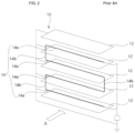
As illustrated in FIGS. 1 and 2 , the electrical dust collecting apparatus described above mainly includes an electrification device 10 and a dust collecting device 20. The electrification device 10 includes a case 11 formed to be hollowed in a direction in which dust is introduced and having a frame shape, electrification plates 12 fixed to the case 11 and formed in parallel with the direction in which the dust is introduced, and a wire 14 provided between the electrification plates 12. In this case, a high voltage is applied to the wire 14 to allow the dust particles to have specific electric charges through a corona discharge phenomenon between the electrification plates 12 and the wire 14. In FIG. 2 , portions of the wire provided between the electrification plates 12 are denoted by reference numeral 14 a, and portions of the wire connecting these portions to each other are denoted by reference numeral 14 b.
The dust collecting device 20 collects the dust particles having the specific electric charges through the discharge in the electrification device 10 as described above by an electrical attractive force using opposite electric charge characteristics.
Particularly, the dust collecting apparatus generates the discharge phenomenon between the electrification plate and the wire to allow the dust particles to have the specific electric charges. In this case, the electrification plate needs to be disposed at an accurate position in order to achieve uniform discharge.
Meanwhile, conventionally, a technology of punching, bending, and assembling one electrification plate has been suggested. However, in a case in which the bent electrification plate is not disposed at an accurate position, it is difficult for the discharge to be effectively achieved, and an abnormal discharge phenomenon between the electrification plate and the wire may occur.
Therefore, a technology for an electrical dust collecting apparatus that may be easily manufactured and may achieve uniform and stable electrification has been demanded.
RELATED ART DOCUMENT Patent Document
(Patent Document 1) Korean Patent Publication No. 10-0495627 (entitled “Electronic Dust Collecting Apparatus using Urethane Filter” and published on Jun. 27, 2005)
SUMMARY
An embodiment of the present invention is directed to providing an electrification device and an electrical dust collecting apparatus including the same capable of having uniform electrification by fixing an electrification plate and a wire at accurate positions using a fixing member coupled to a case to support both end portions of the electrification plate and the wire.
Particularly, an embodiment of the present invention is directed to providing an electrification device and an electrical dust collecting apparatus including the same in which a position of an electrification plate may be accurately supported through a fixing member (or a fixing member and a case) and protrusion portions and a single wire may be supported by a wire support portion so that it may be bent and extend between neighboring electrification plates.
Further, an embodiment of the present invention is directed to providing an electrification device and an electrical dust collecting apparatus including the same in which a fixing member may surround and fix both end portions of an electrification plate and perform an insulation role, and a blocking portion may block between the electrification plate and a wire to prevent abnormal electrification between the electrification plate and the wire adjacent to the electrification plate, thereby enabling stable electrification and improving entire electrification efficiency.
In one general aspect, an electrification device 100 for an electrical dust collecting apparatus, applying electric charges to dust particles introduced from the outside includes: a case 110 having a frame shape; electrification plates 120 coupled to the case 110 to electrify electric charges and having a shape of a plate parallel with a direction in which the dust particles move; a wire 140 disposed to be spaced apart from the electrification plates 120 and be in parallel with the electrification plates 120 and having a high voltage applied thereto; and a pair of fixing members 130 coupled to the case 110 and supporting both end portions of the electrification plates 120 and the wire 140.
In addition, concave seating portions 111 may be formed in the case 110 so that both end portions of the electrification plates 120 are seated.
In addition, first reinforcing portions 113 connecting both sides of the case 110 to each other in a direction in which the electrification plates 120 are mounted may be formed integrally with the case 110.
Further, some of the first reinforcing portions 113 may support one sides of the electrification plates 120 in the direction in which the dust particles move.
In addition, second reinforcing portions 114 connecting both sides of the case 110 in a direction perpendicular to the first reinforcing portions 113 to each other may be formed integrally with the case 110.
Further, the case 110 may include first and second protrusion portions 115 and 116 protruding from the second reinforcing portions 114 and supporting both side surfaces of the electrification plates 120.
In addition, the first protrusion portions 115 and the second protrusion portions 116 may be provided in the second reinforcing portions 114 so as to be spaced apart from each other by a predetermined distance in a length direction of the electrification plates 120.
In addition, the case 110 may include concave first groove portions 114 a formed between the first protrusion portions 115 and the second protrusion portions 116 of the second reinforcing portions 114 so that one sides of the electrification plates 120 are inserted.
Further, the case 110 may include second groove portions 113 a formed in the first reinforcing portions 113 together with the first groove portions 114 a of the second reinforcing portions 114 so as to support entirety of one sides of the electrification plates 120 in the length direction of the electrification plates 120.
In addition, a first corresponding portion 112 that is convex or concave may be formed in the case 110, and a second corresponding portion 133 corresponding to the first corresponding portion 112 may be formed in the fixing member 130 and be assembled to the first corresponding portion 112.
In addition, the fixing member 130 may include a pair of first fixing portions 131 formed so as to support both surfaces of the electrification plate 120.
In addition, second and third fixing portions 132 and 116 each supporting both surfaces of the electrification plate 120 may be formed in the fixing member 130 and the case 110, respectively.
Further, a wire support portion 134 supporting the wire 140 may be formed in the fixing member 130.
In addition, the wire support portion 134 may include a first support portion 134 a having a “
Figure US11607695-20230321-P00001
” shape and supporting the wire 140 provided to be spaced apart from the electrification plate 120 and be in parallel with the electrification plate 120 and a second support portion 134 b supporting the wire 140 so that the wire 140 is bent and extends between neighboring electrification plates 120.
In addition, the fixing member 130 may include a blocking portion 135 protruding to block between the electrification plate 120 and the wire 140.
In another general aspect, an electrical dust collecting apparatus 1000 includes: the electrification device 100 as described above; and a dust collecting device 200.
In addition, the dust collecting device 200 may collect the dust particles electrified in the electrification device 100 by an electrical attractive force or may be a filter passing only air therethrough and collecting only the dust particles.
BRIEF DESCRIPTION OF THE DRAWINGS
FIGS. 1 and 2 are, respectively, a plan view and a partial cross-sectional view illustrating a dust collecting device of an electrical dust collecting apparatus according to the related art.
FIG. 3 is a view illustrating an electrical dust collecting apparatus according to the present invention.
FIGS. 4 and 5 are, respectively, a perspective view and a partially enlarged view illustrating an electrification device according to the present invention.
FIGS. 6 and 7 are, respectively, a partial perspective view illustrating and a cross-sectional view taken along line A-A′ of a case of the electrification device according to the present invention (formation regions of first and second reinforcing portions).
FIG. 8 is a partial perspective view illustrating another case of the electrification device according to the present invention.
FIG. 9 is a schematic view illustrating the electrification device according to the present invention.
FIG. 10 is a view illustrating a mounted state of the case and an electrification plate of the electrification device according to the present invention.
FIGS. 11 and 12 are views illustrating forms of the case and a fixing member of the electrification device according to the present invention.
DETAILED DESCRIPTION OF MAIN ELEMENTS
1000:  electrical dust
collecting apparatus
100: electrification device
110: case
111: seating portion
112: first corresponding portion
113: first reinforcing portion  113a: second groove portion
114: second reinforcing portion
 114a: first groove portion
115: first protrusion portion 116: second protrusion
portion
116: third fixing portion
120: electrification plate
130: fixing member
131: first fixing portion 132: second fixing portion
133: second corresponding portion
134: wire support portion
 134a: first support portion  134b: second support portion
135: blocking portion
140: wire
200: dust collecting device
DETAILED DESCRIPTION OF EMBODIMENTS
Hereinafter, an electrification device 100 having the configuration as described above and an electrical dust collecting apparatus 1000 including the same will be described in detail with reference to the accompanying drawings.
FIG. 3 is a view illustrating an electrical dust collecting apparatus 1000 according to the present invention, FIGS. 4 and 5 are, respectively, a perspective view and a partially enlarged view illustrating an electrification device 100 according to the present invention, FIGS. 6 and 7 are, respectively, a partial perspective view illustrating and a cross-sectional view taken along line A-A′ of a case of the electrification device 100 according to the present invention (formation regions of first and second reinforcing portions 113 and 114), FIG. 8 is a partial perspective view illustrating another case 110 of the electrification device 100 according to the present invention, FIG. 9 is a schematic view illustrating the electrification device 100 according to the present invention, FIG. 10 is a view illustrating a mounted state of the case 110 and an electrification plate 120 of the electrification device 100 according to the present invention, and FIGS. 11 and 12 are views illustrating forms of the case 110 and a fixing member 130 of the electrification device 100 according to the present invention.
The electrical dust collecting apparatus 1000 according to the present invention includes an electrification device 100 and a dust collecting device 200. The electrification device 100 applies electric charges to dust particles introduced from the outside to electrify the dust particles through a corona discharge phenomenon, thereby allowing the dust particles to have selected electric charge characteristics. First, the dust collecting device 200 may be formed to be capable of collecting the dust particles passing through the electrification device 100 to have the selected electric charge characteristics by an electrical attractive force. In this case, the dust collecting device 200 may be a filter formed of several materials having electrical properties. In addition, second, the dust collecting device 200 may be a filter passing air therethrough and collecting only the dust particles, such as a non-woven filter. In addition, the electrification device 100 and the dust collecting device 200 may be coupled to each other in a direction in which the dust particles are introduced and electrified.
Hereinafter, the electrification device 100 of the electrical dust collecting apparatus 1000 according to the present invention will be described in more detail.
The electrification device 100 is configured to include a case 110, electrification plates 120, a wire 140, and fixing members 130.
The case 110, which is a basic body forming the electrification device 100, and is formed in a shape of a frame hollowed in a direction in which dust particles are introduced. In this case, the case 110 may include a plurality of first reinforcing portions 113 formed in order to reinforce durability in a direction in which the electrification plates 120 are provided, and further include second reinforcing portions 114 formed in a direction perpendicular to the first reinforcing portions 113. The first reinforcing portions 113 and the second reinforcing portions 114 may be formed within a range in which they do not hinder a flow of air. An example in which the number of first reinforcing portions 113 is fourteen and the number of second reinforcing portions is three is illustrated in FIG. 4 , but the electrical dust collecting apparatus 1000 according to the present invention is not limited thereto.
The electrification plates 120 are coupled to the case 110, have a shape of a plate parallel with a direction in which the dust particles move, and are provided in the plural. The electrification plate 120 is primarily coupled to (seated in) the case 110, and is secondarily and finally coupled to the case 110 by fixing of the fixing member 130 and the case 110.
First, a form in which the electrification plates 120 are seated in the case 110 will be described.
Concave seating portions 111 are formed in the case 110 so that both end portions of the electrification plates 120 are seated (see FIG. 10 ). The seating portions 111 are portions into which both end portions of the electrification plate 120 are inserted.
In addition, in the case 110, the first reinforcing portions 113 may be formed so as to support one sides of the electrification plates 120 in the direction in which the dust particles move. In this case, some or all of the first reinforcing portions 113 may be formed so as to support one sides of the electrification plates 120, and an example of the first reinforcing portions 113 supporting one side of the electrification plate 120 and general first reinforcing portions 113 are alternately formed is illustrated in FIG. 4 .
In addition, in the case 110, first protrusion portions 115 and second protrusion portions 116 may be formed on the second reinforcing portions 114. The first protrusion portions 115 and the second protrusion portions 116, which are portions protruding form the second reinforcing portions 114 and supporting both surfaces of the electrification plates 120, protrude from a region in which the second reinforcing portions 114 are formed in a length direction of the electrification plates 120 to support the electrification plates 120. In this case, the first protrusion portions 115 and the second protrusion portions 116 may be provided so as to be spaced apart from each other by a predetermined distance in the length direction of the electrification plate 120 so that the electrification plate 120 is easily mounted.
In this case, the case 110 may include concave first groove portions 114 a formed between the first protrusion portions 115 and the second protrusion portions 116 of the second reinforcing portions 114 so that one sides of the electrification plates 120 are further inserted (see FIG. 7 ).
In addition, the case 110 may include second groove portions 113 a formed in the first reinforcing portions 113 so that the entirety of one sides of the electrification plates 120 may be inserted, together with the first groove portions 114 a (see FIG. 8 ).
That is, in the electrical dust collecting apparatus 1000 according to the present invention, both ends of the electrification plates 120 are seated in the seating portions 111 in the case 110 of the electrification device 100, predetermined regions of one sides of the electrification plates 120 are inserted into the first groove portions 114 a and the second groove portions 113 a, such that the electrification plates 120 are supported by the first reinforcing portions 113, and both surfaces of the electrification plates 120 are supported by the first protrusion portions 115 and the second protrusion portions 116 of the second reinforcing portions 114, such that the electrification plates 120 may be maintained in a fixed state at accurate positions.
The wire 140, which is a portion lengthily formed between the electrification plates 120, is disposed to be spaced apart from the electrification plates 120 and be in parallel with the electrification plates 120. The wire 140 may be provided in a form in which a single wire 140 is bent in the entirety of the electrification device 100. The wire 140 applies a high voltage to the dust particles introduced into the case 110. In more detail, the dust particles are introduced into regions between the electrification plates 120 and the wire 140 within the case 110, and the wire 140 may be positioned at centers between the plurality of electrification plates 120 to allow uniform electrification to be generated (see FIG. 9 ).
The fixing member 130 is coupled to the case 110 and supports both end portions of the electrification plate 120 and the wire 140. The fixing member 130 is formed of an insulating material, and is coupled to the case 110 to support the electrification plate 120 and the wire 140, thereby allowing the electrification plate 120 and the wire 140 to be fixed at accurate positions. The fixing member 130 may have a form in which a pair of first fixing portions 131 supporting both surfaces of the electrification plate 120 are formed, as illustrated in FIG. 11 . In addition, as illustrated in FIG. 12 , a second fixing portion 132 supporting one side of the electrification plate 120 may be formed in the fixing member 130 and a third fixing portion 116 supporting the other side of the electrification plate 120 may be formed in the case 110, so as to support both surfaces of the electrification plate 120 together with the case 110. That is, the fixing member 130, which is a component supporting predetermined regions of both end portions of the electrification plate 120, allows the electrification plate 120 to be fixed at an accurate position.
In addition, a wire support portion 134 supporting the wire 140 is formed in the fixing member 130. The wire support portion 134 may include a first support portion 134 a and a second support portion 134 b. The first support portion 134 a has a “
Figure US11607695-20230321-P00001
” shape so that the wire 140 is provided to an accurate position between the plurality of electrification plates 120, and the wire 140 is seated in the first support portion 134 a. That is, the wire 140 may be fixed at the accurate position through the first support portion 134 a. The second support portion 134 b is a portion supporting the wire 140 so that the wire 140 is bent and extends between neighboring electrification plates 120, in a region in which the fixing member 130 is formed. Therefore, the single wire 140 is bent, such that the wire 140 may be provided between the plurality of electrification plates 120. The second support portion 134 b may have a form in which it includes a curved portion so as to be able to easily guide the wire 140.
In this case, the fixing member 130 is formed of an insulating material and prevents abnormal electrification between the electrification plate 120 and the wire 140, and particularly, it is preferable that a blocking portion 135 may further protrude between the first and third fixing portions 131 and 116 supporting the electrification plate 120 and the wire support portion 134 supporting the wire 140 to improve stability.
Meanwhile, the fixing member 130 and the case 110 may be coupled to each other in various manners. As an example, a first corresponding portion 112 that is convex or concave may be formed in the case 110, and a second corresponding 133 portion corresponding to the first corresponding portion 112 may be formed in the fixing member 130. In FIGS. 4 and 5 , the first corresponding portion 112 having a convex shape is formed in the case 110 and the second corresponding portion hollowed so that the first corresponding portion 112 is inserted thereinto is formed in the fixing member 130 is illustrated.
The manufacturing of the electrification device of the electrical dust collecting apparatus 1000 according to the present invention will be described. First, the electrification plates 120 are seated so as to be inserted into the seating portions 111, the first groove portions 114 a, the second groove portions 113 a, the first protrusion portions 115, and the second protrusion portions 116. Next, the fixing members 130 are fixed to the case 110, and the wire 140 is then mounted in the seating portions 111 of the case 110.
Therefore, the electrical dust collecting apparatus 1000 according to the present invention has uniform electrification performance by fixing the electrification plates 120 and the wire 140 at the accurate positions using the fixing members 130 coupled to the case 110 to support both end portions of the electrification plates 120 and the wire 140.
Therefore, the electrification device and the electrical dust collecting apparatus including the same according to the present invention may have uniform electrification by fixing an electrification plate and a wire at accurate positions using a fixing member coupled to a case to support both end portions of the electrification plate and the wire.
Particularly, in the electrification device and the electrical dust collecting apparatus including the same, a position of an electrification plate may be accurately supported through a fixing member (or a fixing member and a case) and protrusion portions and a single wire may be supported by a wire support portion so that it may be bent and extend between neighboring electrification plates.
Further, in the electrification device and the electrical dust collecting apparatus including the same, a fixing member may surround and fix both end portions of an electrification plate and perform an insulation role, and a blocking portion may block between the electrification plate and a wire to prevent abnormal electrification between the electrification plate and the wire adjacent to the electrification plate, thereby enabling stable electrification and improving entire electrification efficiency.
The present invention is not limited to the abovementioned exemplary embodiments, but may be variously applied. In addition, the present invention may be variously modified by those skilled in the art to which the present invention pertains without departing from the gist of the present invention claimed in the claims.

Claims (11)

What is claimed is:
1. An electrification device for an electrical dust collecting apparatus, applying electric charges to dust particles introduced from the outside, comprising:
a case having a frame shape;
electrification plates coupled to the case to electrify dust particles and having a shape of a plate parallel with a direction in which the dust particles move;
a wire disposed spaced apart from the electrification plates and in parallel with the electrification plates and having a high voltage applied thereto; and
a fixing member coupled to one surface of the case and supporting the electrification plates and the wire;
wherein the fixing member includes a pair of first fixing portions formed so as to support as to support a front surface and a back surface of each of the electrification plates; and
a wire support portion supporting the wire;
wherein the fixing member further includes a blocking portion protruding to block between the electrification plate and the wire,
wherein the wire support portion includes a first support portion having a “c” shape and supporting the wire provided to be spaced apart from the electrification plates and in parallel with the electrification plates and a second support portion supporting the wire so that the wire is bent and extends between neighboring electrification plates.
2. The electrification device for the electrical dust collecting apparatus of claim 1, wherein concave seating portions are formed in the case so that both end portions of the electrification plates are seated.
3. The electrification device for the electrical dust collecting apparatus of claim 2, wherein first reinforcing portions connecting one side and an other side of the case to each other in a direction in which the electrification plates are mounted; and second reinforcing portions connecting one side and the other side of the case in a direction perpendicular to the first reinforcing portions are formed in the case.
4. The electrification device for the electrical dust collecting apparatus of claim 3, wherein the first reinforcing portions support one side of the electrification plates in a direction in which the dust particles move.
5. The electrification device for the electrical dust collecting apparatus of claim 3, wherein the case includes first protrusion portions protruding from the second reinforcing portions and supporting the front surface of the electrification plates and second protrusion portions protruding from the second reinforcing portions and supporting the back surface of the electrification plates.
6. The electrification device for the electrical dust collecting apparatus of claim 5, wherein the first protrusion portions and the second protrusion portions are provided in the second reinforcing portions so as to be spaced apart from each other by a predetermined distance in a length direction of the electrification plates.
7. The electrification device for the electrical dust collecting apparatus of claim 6, wherein the case includes concave first groove portions formed between the first protrusion portions and the second protrusion portions of the second reinforcing portions so that lower sides of the electrification plates are inserted.
8. The electrification device for the electrical dust collecting apparatus of claim 7, wherein the case includes second groove portions formed in the first reinforcing portions together with the first groove portions of the second reinforcing portions so as to support entirety of the lower sides of the electrification plates in the length direction of the electrification plates.
9. An electrical dust collecting apparatus comprising:
the electrification device of claim 1; and
a dust collecting device.
10. The electrical dust collecting apparatus of claim 9, wherein the dust collecting device collects the dust particles electrified in the electrification device by an electrical attractive force.
11. The electrical dust collecting apparatus of claim 9, wherein the dust collecting device is a filter passing only air therethrough and collecting only the dust particles.
US16/724,665 2019-01-18 2019-12-23 Electrification device and electrical dust collecting apparatus including the same Active 2041-04-22 US11607695B2 (en)

Applications Claiming Priority (2)

Application Number Priority Date Filing Date Title
KR10-2019-0006627 2019-01-18
KR1020190006627A KR102634227B1 (en) 2019-01-18 2019-01-18 Electrification device and electric Dust device having the same

Publications (2)

Publication Number Publication Date
US20200230611A1 US20200230611A1 (en) 2020-07-23
US11607695B2 true US11607695B2 (en) 2023-03-21

Family

ID=71403072

Family Applications (1)

Application Number Title Priority Date Filing Date
US16/724,665 Active 2041-04-22 US11607695B2 (en) 2019-01-18 2019-12-23 Electrification device and electrical dust collecting apparatus including the same

Country Status (4)

Country Link
US (1) US11607695B2 (en)
KR (1) KR102634227B1 (en)
CN (1) CN111450998A (en)
DE (1) DE102020100772A1 (en)

Families Citing this family (1)

* Cited by examiner, † Cited by third party
Publication number Priority date Publication date Assignee Title
KR20230059422A (en) * 2021-10-26 2023-05-03 한온시스템 주식회사 Electrification part and Electric dust collector having the same

Citations (7)

* Cited by examiner, † Cited by third party
Publication number Priority date Publication date Assignee Title
US3997304A (en) * 1975-03-28 1976-12-14 Carrier Corporation Mounting system of ionizing wires of electrostatic precipitator
KR20040007007A (en) 2002-07-16 2004-01-24 삼성전자주식회사 Electronic dust collecting apparatus using urethane filter
CN1735775A (en) 2003-01-07 2006-02-15 Lg电子株式会社 Plasma air dust collector
US20070028775A1 (en) * 2005-08-03 2007-02-08 Valeo Systemes Thermiques S.A.S. Device for ionizing particles carried in an airflow, for ventilation, heating, and/or air-conditioning system in particular
US20150290352A1 (en) 2012-04-23 2015-10-15 Mitsubishi Electric Corporation Corona discharge device and air-conditioning apparatus
CN206778712U (en) 2017-03-17 2017-12-22 浙江菲达环保科技股份有限公司 A kind of wet electrical dust precipitator anode assembly
WO2018143742A2 (en) 2017-02-03 2018-08-09 (주)동일기연 Filtering device

Family Cites Families (9)

* Cited by examiner, † Cited by third party
Publication number Priority date Publication date Assignee Title
SE412012B (en) * 1978-06-22 1980-02-18 Elfi Elektrofilter Ab FIXING AND CONNECTING DEVICE FOR WIRE AND PLATES IN ELECTROSTATIC FILTERS
CN102383175B (en) * 2011-10-26 2014-06-18 首都航天机械公司 Backpressure type electrolytic etching processing device
CN102430477B (en) * 2011-12-28 2014-11-26 艾尼科环保技术(安徽)有限公司 Electrostatic dust remover with movable electrode plate
KR101741516B1 (en) * 2015-05-15 2017-05-30 전주비전대학교산학협력단 Book Binder with perforating hole under and control rotation degree
KR101839557B1 (en) * 2015-10-30 2018-04-26 엘지전자 주식회사 Electric Dust Collection Device and Air Conditioner comprising the same
KR20170051893A (en) * 2015-11-03 2017-05-12 현대자동차주식회사 Electric Dust Collector
KR101963786B1 (en) * 2017-02-03 2019-07-31 (주)동일기연 Filtering apparatus including electrification part
CN107029891B (en) * 2017-06-01 2019-06-18 安徽机电职业技术学院 A kind of cathode of electric dust collector frame
CN207146637U (en) * 2017-09-11 2018-03-27 广东美的制冷设备有限公司 Electrostatic precipitator and air conditioner

Patent Citations (9)

* Cited by examiner, † Cited by third party
Publication number Priority date Publication date Assignee Title
US3997304A (en) * 1975-03-28 1976-12-14 Carrier Corporation Mounting system of ionizing wires of electrostatic precipitator
KR20040007007A (en) 2002-07-16 2004-01-24 삼성전자주식회사 Electronic dust collecting apparatus using urethane filter
CN1735775A (en) 2003-01-07 2006-02-15 Lg电子株式会社 Plasma air dust collector
US20070028775A1 (en) * 2005-08-03 2007-02-08 Valeo Systemes Thermiques S.A.S. Device for ionizing particles carried in an airflow, for ventilation, heating, and/or air-conditioning system in particular
US20150290352A1 (en) 2012-04-23 2015-10-15 Mitsubishi Electric Corporation Corona discharge device and air-conditioning apparatus
US9457118B2 (en) * 2012-04-23 2016-10-04 Mitsubishi Electric Corporation Corona discharge device and air-conditioning apparatus
WO2018143742A2 (en) 2017-02-03 2018-08-09 (주)동일기연 Filtering device
US20200179946A1 (en) * 2017-02-03 2020-06-11 Dong Il Technology Ltd. Filtering device
CN206778712U (en) 2017-03-17 2017-12-22 浙江菲达环保科技股份有限公司 A kind of wet electrical dust precipitator anode assembly

Non-Patent Citations (1)

* Cited by examiner, † Cited by third party
Title
Office Action dated Aug. 3, 2022 by the CIPO in the corresponding Patent Application No. CN 202010052226.1, with English translation.

Also Published As

Publication number Publication date
CN111450998A (en) 2020-07-28
US20200230611A1 (en) 2020-07-23
KR20200089857A (en) 2020-07-28
KR102634227B1 (en) 2024-02-07
DE102020100772A1 (en) 2020-07-23

Similar Documents

Publication Publication Date Title
US11484889B2 (en) Electrification device and electrical dust collecting apparatus including the same
JP5774212B2 (en) Corona discharge device and air conditioner
CN110732411B (en) Charging device for electric dust collection and air conditioner for vehicle comprising same
US20050031946A1 (en) Battery assembly and method of making same
TWI552801B (en) Electrical screening device for structures near high voltage parts of electrostatic precipitators
JP2007038220A (en) Suspended particle ionizing apparatus for air conditioner
US11607695B2 (en) Electrification device and electrical dust collecting apparatus including the same
KR20100122274A (en) Electric precipitator
CN110732410B (en) Charging device for electric dust collection and air conditioner for vehicle comprising same
CA2897143A1 (en) Restraint for group-cell, restraining member for group-cell, and battery
US7090717B2 (en) Air purifier
WO2013054428A1 (en) Apparatus for generating electric field and electric discharge
US20220250088A1 (en) Electric precipitator
US20160312802A1 (en) Piezo fan
JP2015016405A (en) Air cleaning unit
KR102639348B1 (en) Electrification device and electric Dust device having the same
US2714939A (en) Electrostatic precipitators
JPH11207208A (en) Air cleaner
US11878262B2 (en) Filter module
JP6812846B2 (en) Electrostatic precipitator
CN114729757B (en) air conditioner
KR102572534B1 (en) Collector for electric precipitator
JPH02164466A (en) Electric dust collector
KR200295210Y1 (en) Electric dust collector
KR20100125319A (en) Contact spring

Legal Events

Date Code Title Description
FEPP Fee payment procedure

Free format text: ENTITY STATUS SET TO UNDISCOUNTED (ORIGINAL EVENT CODE: BIG.); ENTITY STATUS OF PATENT OWNER: LARGE ENTITY

AS Assignment

Owner name: HANON SYSTEMS, KOREA, REPUBLIC OF

Free format text: ASSIGNMENT OF ASSIGNORS INTEREST;ASSIGNORS:PARK, JI-YONG;KIM, KI HONG;KIM, JAE HO;SIGNING DATES FROM 20191220 TO 20191223;REEL/FRAME:051376/0878

STPP Information on status: patent application and granting procedure in general

Free format text: DOCKETED NEW CASE - READY FOR EXAMINATION

STPP Information on status: patent application and granting procedure in general

Free format text: NON FINAL ACTION MAILED

STPP Information on status: patent application and granting procedure in general

Free format text: RESPONSE TO NON-FINAL OFFICE ACTION ENTERED AND FORWARDED TO EXAMINER

STPP Information on status: patent application and granting procedure in general

Free format text: FINAL REJECTION MAILED

STPP Information on status: patent application and granting procedure in general

Free format text: RESPONSE AFTER FINAL ACTION FORWARDED TO EXAMINER

STCF Information on status: patent grant

Free format text: PATENTED CASE