US11605484B2 - Multilayer seed pattern inductor and manufacturing method thereof - Google Patents
Multilayer seed pattern inductor and manufacturing method thereof Download PDFInfo
- Publication number
- US11605484B2 US11605484B2 US16/803,315 US202016803315A US11605484B2 US 11605484 B2 US11605484 B2 US 11605484B2 US 202016803315 A US202016803315 A US 202016803315A US 11605484 B2 US11605484 B2 US 11605484B2
- Authority
- US
- United States
- Prior art keywords
- seed pattern
- coating layer
- coil conductors
- layer
- spiral
- Prior art date
- Legal status (The legal status is an assumption and is not a legal conclusion. Google has not performed a legal analysis and makes no representation as to the accuracy of the status listed.)
- Active, expires
Links
Images


Classifications
-
- H—ELECTRICITY
- H01—ELECTRIC ELEMENTS
- H01F—MAGNETS; INDUCTANCES; TRANSFORMERS; SELECTION OF MATERIALS FOR THEIR MAGNETIC PROPERTIES
- H01F17/00—Fixed inductances of the signal type
- H01F17/0006—Printed inductances
- H01F17/0013—Printed inductances with stacked layers
-
- H—ELECTRICITY
- H01—ELECTRIC ELEMENTS
- H01F—MAGNETS; INDUCTANCES; TRANSFORMERS; SELECTION OF MATERIALS FOR THEIR MAGNETIC PROPERTIES
- H01F27/00—Details of transformers or inductances, in general
- H01F27/24—Magnetic cores
- H01F27/255—Magnetic cores made from particles
-
- H—ELECTRICITY
- H01—ELECTRIC ELEMENTS
- H01F—MAGNETS; INDUCTANCES; TRANSFORMERS; SELECTION OF MATERIALS FOR THEIR MAGNETIC PROPERTIES
- H01F41/00—Apparatus or processes specially adapted for manufacturing or assembling magnets, inductances or transformers; Apparatus or processes specially adapted for manufacturing materials characterised by their magnetic properties
- H01F41/02—Apparatus or processes specially adapted for manufacturing or assembling magnets, inductances or transformers; Apparatus or processes specially adapted for manufacturing materials characterised by their magnetic properties for manufacturing cores, coils, or magnets
- H01F41/04—Apparatus or processes specially adapted for manufacturing or assembling magnets, inductances or transformers; Apparatus or processes specially adapted for manufacturing materials characterised by their magnetic properties for manufacturing cores, coils, or magnets for manufacturing coils
- H01F41/041—Printed circuit coils
- H01F41/046—Printed circuit coils structurally combined with ferromagnetic material
Definitions
- the present disclosure relates to a multilayer seed pattern inductor and a manufacturing method thereof.
- An inductor, an electronic component, is a representative passive element that is commonly used in electronic circuits together with a resistor and a capacitor to remove noise.
- a thin film type inductor can be manufactured by forming an internal coil part by plating, forming a magnetic body by curing a magnetic powder-resin composite obtained by mixing magnetic powder and a resin with each other, and then forming external electrodes on external surfaces of the magnetic body.
- An aspect of the present disclosure may provide a multilayer seed pattern inductor in which direct current resistance (Rdc) is decreased by increasing a cross-sectional area of an internal coil part, and a manufacturing method thereof.
- Rdc direct current resistance
- a multilayer seed pattern inductor may include an internal coil part embedded in a magnetic body and including connected coil conductors disposed on two opposing surfaces of an insulating substrate.
- Each of the coil conductors may include a seed pattern including at least two layers, a surface coating layer covering the seed pattern, and an upper plating layer formed on an upper surface of the surface coating layer.
- a method of manufacturing a multilayer seed pattern inductor may include forming coil conductors on two opposing surfaces of an insulating substrate to form an internal coil part, and stacking magnetic sheets on upper and lower surfaces of the internal coil part to form a magnetic body.
- the forming of the coil conductors can include forming a seed pattern including at least two layers on the insulating substrate, forming a surface coating layer covering the seed pattern, and forming an upper plating layer on an upper surface of the surface coating layer.
- a method of forming a multilayer coil inductor may include forming a seed pattern having a spiral shape on an insulating substrate, forming a surface coating layer covering the seed pattern, and forming an upper plating layer on an upper surface of the surface coating layer.
- the forming of the seed pattern may include forming a first plating resist on the insulating substrate, forming an opening in the first plating resist by exposure and development, forming a first seed pattern including a conductive metal in the opening in the first plating resist by plating, forming a second plating resist on the first plating resist and the first seed pattern, forming an opening in the second plating resist through exposure and development to expose the first seed pattern, forming a second seed pattern including the conductive metal in the opening in the second plating resist by plating, and removing the first and second plating resists.
- FIG. 1 is a schematic perspective view illustrating a multilayer seed pattern inductor according to an exemplary embodiment
- FIG. 2 is a cross-sectional view taken along line I-I′ of FIG. 1 ;
- FIG. 3 is an enlarged schematic view of one illustrative example of part ‘A’ of FIG. 2 ;
- FIG. 4 is an enlarged schematic view of another illustrative example of part ‘A’ of FIG. 2 ;
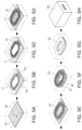
- FIGS. 5 A through 5 H are diagrams illustrating sequential steps of a method of manufacturing a multilayer seed pattern inductor according to an exemplary embodiment
- FIGS. 6 A through 6 F are diagrams illustrating sequential steps of a method for forming a seed pattern according to an exemplary embodiment
- FIG. 7 is a view illustrating a formation method of a surface coating layer according to an exemplary embodiment.
- FIG. 8 is a view illustrating a formation method of an upper plating layer according to an exemplary embodiment.
- first, second, third, etc. may be used herein to describe various members, components, regions, layers and/or sections, these members, components, regions, layers and/or sections should not be limited by these terms. These terms are only used to distinguish one member, component, region, layer or section from another region, layer or section. Thus, a first member, component, region, layer or section discussed below could be termed a second member, component, region, layer or section without departing from the teachings of the exemplary embodiments.
- spatially relative terms such as “above,” “upper,” “below,” and “lower” and the like, may be used herein for ease of description to describe one element's position-based relationship to another element (s) as shown in the figures. It will be understood that the spatially relative terms are based on the particular orientations shown in the figures, and are intended to encompass different orientations of the device in use or operation in addition to the orientation depicted in the figures. For example, if the device in the figures is turned over, elements described as “above,” or “upper” other elements would then be oriented “below,” or “lower” the other elements or features. Thus, the term “above” can encompass both the above and below orientations depending on a particular direction of the figures. The device may be otherwise oriented (rotated 90 degrees or at other orientations) and the spatially relative descriptors used herein may be interpreted accordingly.
- embodiments of the present inventive concepts will be described with reference to schematic views illustrating exemplary embodiments. However, due to manufacturing techniques and/or tolerances, actual manufactured embodiments may differ slightly from the illustrated embodiments. Thus, embodiments of the present inventive concepts should not be construed as being limited to the particular shapes of regions shown herein but should be interpreted as including, for example, a change in shape resulting from the manufacturing processes. The following embodiments may also be constituted by one or a combination thereof.
- FIG. 1 is a schematic perspective view illustrating a multilayer seed pattern inductor according to an exemplary embodiment in the present disclosure.
- a body of the multilayer seed pattern inductor is illustratively shown as being transparent so that an internal coil part is visible.
- a thin film type inductor used in a power line of a power supply circuit is disclosed as an example of a multilayer seed pattern inductor 100 .
- the multilayer seed pattern inductor 100 may include a magnetic body 50 , an internal coil part 40 embedded in the magnetic body 50 , and first and second external electrodes 81 and 82 disposed on external surfaces of the magnetic body 50 to thereby be electrically connected to respective ends of the internal coil part 40 .
- a ‘length’ direction refers to an ‘L’ direction of FIG. 1
- a ‘width’ direction refers to a ‘W’ direction of FIG. 1
- a ‘thickness’ direction refers to a ‘T’ direction of FIG. 1 .
- the magnetic body 50 may form at least a portion of an exterior of the multilayer seed pattern inductor 100 and may be formed of any material that exhibits magnetic properties.
- the magnetic body 50 may be formed of ferrite and/or a magnetic metal powder, or of a material including ferrite and/or the magnetic metal powder.
- the ferrite may be, for example, an Mn—Zn based ferrite, an Ni—Zn based ferrite, an Ni—Zn—Cu based ferrite, an Mn-Mg based ferrite, a Ba based ferrite, an Li based ferrite, or the like.
- the magnetic metal powder may contain any one or more selected from the group consisting of Fe, Si, Cr, Al, and Ni.
- the magnetic metal powder may contain a Fe—Si—B—Cr—based amorphous metal, but is not limited thereto.
- the magnetic metal powder may have a particle diameter of 0.1 ⁇ m to 30 ⁇ m and be dispersed in a thermosetting resin such as an epoxy resin, polyimide, or the like.
- the magnetic body 50 may be formed of the magnetic metal powder and the thermosetting resin that the powder is dispersed in.
- the internal coil part 40 disposed in the magnetic body 50 may be formed by connecting a first coil inductor 41 formed on one surface of an insulating substrate 20 to a second coil conductor 42 formed on the other surface of the insulating substrate 20 that is opposite the one surface.
- the first and second coil conductors 41 and 42 may be formed by an electroplating method. However, a formation method of the first and second coil conductors 41 and 42 is not limited thereto.
- the first and second coil conductors 41 and 42 may be covered with an insulating film (not illustrated) to thereby not directly contact or electrically contact a magnetic material forming the magnetic body 50 .
- the insulating substrate 20 may be, for example, a polypropylene glycol (PPG) substrate, a ferrite substrate, a metal based soft magnetic substrate, or the like.
- PPG polypropylene glycol
- a central portion of the insulating substrate 20 may be penetrated by a through-hole, and the through-hole may be filled with the same magnetic material as the magnetic body 50 , thereby forming a core part 55 .
- inductance (Ls) of the multilayer seed pattern inductor 100 may be improved.
- Each of the first and second coil conductors 41 and 42 may be in a form of a planar coil formed on the same plane of the insulating substrate 20 .
- Each of the first and second coil conductors 41 and 42 may have hole at the center of the coil, and the hole may have substantially the same size as the through-hole penetrating through the insulating substrate 20 .
- the first and second coil conductors 41 and 42 may have a spiral shape, and the first and second coil conductors 41 and 42 formed on one surface and the other surface of the insulating substrate 20 , respectively, may be electrically connected to each other by a via (not illustrated) penetrating through the insulating substrate 20 .
- the first and second coil conductors 41 and 42 are electrically connected in series by the via.
- the first and second coil conductors 41 and 42 and the via may contain or be formed of a metal having excellent electrical conductivity.
- the first and second coil conductors 41 and 42 and the via may be formed of silver (Ag), palladium (Pd), aluminum (Al), nickel (Ni), titanium (Ti), gold (Au), copper (Cu), platinum (Pt), or an alloy thereof, or the like.
- the cross-sectional area of the coil conductor may be increased by forming the internal coil part and increasing a volume of the magnetic material.
- a width of a coil can be increased and/or a thickness of the coil can be increased.
- the risk of the coil failing due to short-circuits between adjacent windings of the coil may be significantly increased.
- efficiency of the coil component maybe decreased, and the constraints outlined above may effectively impose limitations on implementing a high inductance product.
- a coil conductor can be used that has a high aspect ratio (AR) obtained by increasing the thickness of the coil rather than increasing the width of the coil.
- the aspect ratio (AR) of the coil conductor is a value obtained by dividing the thickness of the coil by the width of the coil. As the thickness of the coil is increased to be greater than the width of the coil, the aspect ratio (AR) of the coil may also be increased.
- the plating resist needs to be formed to be relatively thick in order to form the coil to be relatively thick.
- an exposure limit may be reached whereby exposure of a lower portion of the plating resist is not smoothly performed. As such, it may be difficult to increase the thickness of the coil in examples in which the coil conductor is formed using the pattern plating method.
- the plating resist in order to allow a thick plating resist to maintain its shape, the plating resist generally needs to have a width equal to or more than a predetermined width.
- the width of the plating resist directly affects the interval between adjacent coils after removing the plating resist, the interval between the adjacent coils may be increased, such that there is a limitation in improving direct current resistance (Rdc) and inductance (Ls) characteristics.
- a coil conductor capable of having a high aspect ratio (AR), having an increased cross-sectional area, and preventing short-circuits from occurring between adjacent coils while forming an interval between adjacent coils to be narrow, may be implemented.
- the coil conductor may be implemented by forming at least two layers of a seed pattern, forming a surface coating layer covering the seed pattern, and further forming an upper plating layer on an upper surface of the surface coating layer.
- FIG. 2 is a cross-sectional view taken along line I-I′ of FIG. 1 .
- the first and second coil conductors 41 and 42 may each include a first seed pattern 61 a formed on the insulating substrate 20 , a second seed pattern 61 b formed on an upper surface of the first seed pattern 61 a, a surface coating layer 62 covering and fully enclosing the first and second seed patterns 61 a and 61 b, and an upper plating layer 63 formed on an upper surface of the surface coating layer 62 .
- One end portion of the first coil conductor 41 formed on one surface of the insulating substrate 20 may be exposed to one end surface of the magnetic body 50 in the length (L) direction thereof, and one end portion of the second coil conductor 42 formed on the other surface of the insulating substrate 20 may be exposed to the other end surface of the magnetic body 50 in the length (L) direction thereof.
- each of the first and second coil conductors 41 and 42 are not necessarily limited to being exposed as described above, but may each generally be exposed to at least one surface of the magnetic body 50 .
- the first and second external electrodes 81 and 82 may be formed on the external surfaces of the magnetic body 50 to be connected, respectively, to the end portions of first and second coil conductors 41 and 42 exposed to the end surfaces of the magnetic body 50 .
- FIG. 3 is an enlarged schematic view of part ‘A’ of FIG. 2 .
- a seed pattern 61 may include the first seed pattern 61 a and the second seed pattern 61 b formed on the upper surface of the first seed pattern 61 a.
- the surface coating layer 62 may cover (and, optionally, fully enclose) the seed pattern 61
- the upper plating layer 63 may be further formed on the upper surface of the surface coating layer 62 .
- the seed pattern 61 may be formed by a pattern plating method of forming a plating resist pattern using an exposure and development method on the insulation substrate 20 and filling an opening by plating.
- the seed pattern 61 maybe formed of at least two layers including the first and second seed patterns 61 a and 61 b.
- the number of layers of the seed pattern 61 is not limited thereto.
- the seed pattern 61 maybe formed of three layers or more.
- the seed pattern 61 may be formed to have an overall thickness t SP of 100 ⁇ m or more.
- the exposure limitation (which depends on the thickness of the plating resist) may be overcome by the layering of the multiple seed patterns ( 61 a, 61 b ), and the overall thickness t SP of the seed pattern 61 may be implemented to be 100 ⁇ m or more by forming the seed pattern 61 to have a structure composed of at least two layers.
- the seed pattern 61 is formed to have an overall thickness t SP of 100 ⁇ m or more, a thickness of the coil conductors 41 and 42 (e.g., a dimension of the coil conductors 41 and 42 in the thickness direction ‘T’) may be increased, and the coil conductors 41 and 42 having a high aspect ratio (AR) may be implemented.
- a cross-sectional shape of the seed pattern 61 in the thickness (T) direction may be a rectangle.
- the seed pattern 61 may be formed by the pattern plating as described above, and thus, the cross-sectional shape thereof may be rectangular (or substantially rectangular, as shown in FIG. 3 ).
- Each of the first and second coil conductors 41 and 42 may include a thin film conductor layer 25 disposed on a lower seed pattern surface 61 (e.g., disposed between the substrate 20 and the seed pattern 61 ).
- the thin film conductor layer 25 may be formed by performing an electroless plating method or sputtering method on the insulating substrate 20 and performing etching.
- the seed pattern 61 may be formed by performing electroplating on the thin film conductor layer 25 used as a seed layer.
- the surface coating layer 62 covering the seed pattern 61 may be formed by performing electroplating on the seed pattern 61 used as a seed layer.
- the surface coating layer 62 covering the seed pattern 61 may be formed, thereby solving a problem that it is difficult to decrease the interval between adjacent coils of the coil conductors 41 and 42 due to a limitation in decreasing the width of the plating resist at the time of forming only the seed pattern using the pattern plating method.
- the cross-sectional area of the coil conductor may be further increased by the surface coating layer 62 , thereby improving direct current resistance (Rdc) and inductance (Ls) characteristics.
- a growth degree W P1 in the width direction and a growth degree T P1 in the thickness direction may be similar to each other.
- the surface coating layer 62 covering the seed pattern 61 may be formed of an isotropic plating layer of which the growth degree W P1 in the width direction and the growth degree T P1 in the thickness direction may be similar to each other. Further, the coil conductor may have a uniform thickness and a difference in thickness between adjacent coils may be decreased, whereby direct current resistance (Rdc) distribution may be decreased.
- Rdc direct current resistance
- the surface coating layer 62 may be formed of the isotropic plating layer, such that the first and second coil conductors 41 and 42 may not be bent but be straightly formed, thereby preventing short-circuits between adjacent coils and preventing defects in which an insulating film is not formed in portions of the first and second coil conductors 41 and 42 .
- the surface coating layer 62 is not limited thereto. That is, the surface coating layer 62 may be formed of at least two or more layers.
- the upper plating layer 63 formed on the upper surface of the surface coating layer 62 may be formed by performing electroplating.
- the cross-sectional area of the coil conductor may be further increased by further forming the upper plating layer 63 on the surface coating layer 62 , whereby direct current resistance (Rdc) and inductance (Ls) characteristics may be further improved.
- Rdc direct current resistance
- Ls inductance
- growth in the width direction may be suppressed, and a growth degree T P2 in the thickness direction may be significantly high.
- the upper plating layer 63 formed on the surface coating layer 62 may be formed of an anisotropic plating layer of which the growth in the width direction is suppressed and the growth degree T P2 in the thickness direction is significantly high, thereby further increasing the cross-sectional area of the coil conductor while preventing short-circuits between adjacent coils.
- the upper plating layer 63 may be formed on the upper surface of the surface coating layer 62 , and may not cover all side surfaces of the surface coating layer 62 .
- An aspect ratio (AR) of the first and second coil conductors 41 and 42 may be 3.0 or more.
- the AR may be measured as a ratio of a total thickness (e.g., a maximum thickness equal to the sum of t sp , T P1 , and T P2 , or an average thickness) to a total width (e.g., a maximum width, or an average width) of one winding of the coil conductors 41 and 42 .
- FIG. 4 is an enlarged schematic view of another embodiment of part ‘A’ of FIG. 2 .
- an upper plating layer 63 may include a first upper plating layer 63 a formed on the upper surface of the surface coating layer 62 and a second upper plating layer 63 b formed on an upper surface of the first upper plating layer 63 a.
- the first and second upper plating layers 63 a and 63 b may be anisotropic plating layers having growth in the width direction that is suppressed and having a growth degree (T P2 ) in the thickness direction the is significantly high, similarly to the above-mentioned embodiment illustrated in FIG. 3 .
- the upper plating layer 63 may thus be formed of two anisotropic plating layers 63 a and 63 b.
- the cross-sectional area of the coil conductor may be further increased by forming the upper plating layer 63 (e.g., the anisotropic plating layer) to be composed of at least two layers 63 a and 63 b, whereby direct current resistance (Rdc) and inductance (Ls) characteristics may be improved.
- the upper plating layer 63 e.g., the anisotropic plating layer
- Rdc direct current resistance
- Ls inductance
- the upper plating layer 63 is not limited thereto. That is, the upper plating layer 63 may more generally be formed of at least two or more layers.
- FIGS. 5 A through 5 H are diagrams illustrating sequential steps of a method of manufacturing a multilayer seed pattern inductor according to an exemplary embodiment in the present disclosure.
- an insulating substrate 20 may be prepared, and a via hole 45 ′ may be formed in the insulating substrate 20 .
- the via hole 45 ′ may be formed using a mechanical drill or a laser drill, but the formation method of the via hole 45 ′ is not limited thereto.
- the laser drill may be, for example, a CO 2 laser drill or YAG laser drill.
- a thin film conductor layer 25′ may be entirely formed on upper and lower surfaces of the insulating substrate 20 , and a plating resist 71 having an opening for forming a seed pattern may be formed.
- plating resist 71 a general photosensitive resist film, a dry film resist, or the like, may be used, but the plating resist 71 is not limited thereto.
- the opening for forming a seed pattern may be formed by an exposure and development method.
- the opening for forming a seed pattern may be filled with a conductive metal by plating, thereby forming a seed pattern 61 .
- the opening for forming a seed pattern may be filled with the conductive metal by electroplating using the thin film conductor layer 25 ′ as a seed layer, such that the seed pattern 61 may be formed, and the via hole 45 ′ maybe filled with the conductive metal by electroplating, thereby forming a via (not illustrated).
- the seed pattern 61 may be formed of at least two layers, such that coil conductors 41 and 42 may have a high aspect ratio (AR).
- AR aspect ratio
- the plating resist 71 may be removed, and the thin film conductor layer 25 ′ may be etched, such that a thin film conductor layer 25 may only remain below a lower seed pattern surface 61 .
- a surface coating layer 62 covering the seed pattern 61 may be formed, and an upper plating layer 63 may be formed on an upper surface of the surface coating layer 62 .
- the surface coating layer 62 and the upper plating layer 63 may be formed by electroplating.
- portions of the insulating substrate 20 other than regions of the insulating substrate 20 on which are disposed the first and second coil conductors 41 and 42 each including the seed pattern 61 , the surface coating layer 62 , and the upper plating layer 63 , maybe removed.
- a central portion of the insulating substrate 20 may be removed, and thus a core part hole 55 ′ may be formed.
- the insulating substrate 20 may be removed by performing mechanical drilling, laser drilling, sand blasting, punching, or the like.
- an insulating film 30 covering each of the first and second coil conductors 41 and 42 may be formed.
- the insulating film 30 may be formed by a method known in the art such as a screen printing method, an exposure and development method of a photo resist (PR), a spray application method, or the like.
- the insulating film 30 may be formed so as to extend into crevices between adjacent windings of the first and second coil conductors 41 and 42 .
- a magnetic body 50 may be formed by stacking magnetic sheets on upper and lower surfaces of the first and second coil conductors 41 and 42 , and compressing and curing the stacked magnetic sheets.
- the core part hole 55 ′ may be filled with a magnetic material, thereby forming a core part 55 .
- first and second external electrodes 81 and 82 may be formed on external surfaces of the magnetic body 50 to be respectively connected to end portions of the first and second coil conductors 41 and 42 exposed to end surfaces of the magnetic body 50 .
- FIGS. 6 A through 6 F are diagrams illustrating sequential steps of a method for forming the seed pattern according to an exemplary embodiment in the present disclosure.
- a first plating resist 71 a having an opening 71 a ′ for forming a first seed pattern may be formed on an insulating substrate 20 on which a thin film conductor layer 25 ′ is formed to cover an entirety of the surface of the insulating substrate 20 .
- the opening 71 a ′ for forming a first seed pattern may be formed by an exposure and development method.
- a thickness of the first plating resist 71 a may be 40 ⁇ m to 60 ⁇ m.
- a first seed pattern 61 a may be formed by filling the opening 71 a ′ for forming a first seed pattern with a conductive metal using a plating method.
- a second plating resist 71 b having an opening 71 b ′ for forming a second seed pattern may be formed on the first plating resist 71 a.
- the opening 71 b ′ for forming a second seed pattern exposing the first seed pattern 61 a may be formed by an exposure and development method.
- a thickness of the second plating resist 71 b may be 40 ⁇ m to 60 ⁇ m.
- a second seed pattern 61 b may be formed on an upper surface of the first seed pattern 61 a by filling the opening 71 b ′ for forming a second seed pattern with a conductive metal using a plating method.
- the first and second plating resists 71 a and 71 b may be removed.
- the thin film conductor layer 25 ′ may be etched, such that a thin film conductor layer 25 may remain only below a lower surface of the first seed pattern 61 a.
- a seed pattern 61 formed as described above may have a structure composed of two layers.
- a cross-sectional shape of the seed pattern 61 in the thickness (T) direction may be a rectangle, and an overall thickness t SP of the seed pattern 61 may be 100 ⁇ m or more.
- the formation method of the seed pattern is not limited thereto. That is, a seed pattern having a structure composed of at least two or more layers, including at least one internal interface between adjacent layers may be formed by repeatedly performing the methods of FIGS. 6 C and 6 D described above.
- a formation method of a seed pattern having a structure composed of at least two layers is not necessarily limited to the formation method of FIGS. 6 A through 6 F , but the seed pattern having a structure composed of at least two layers may also be formed by performing plating at least two times or more after forming a plating resist to be thicker.
- FIG. 7 is a view illustrating a formation method of the surface coating layer 62 according to an exemplary embodiment in the present disclosure.
- the surface coating layer 62 covering the seed pattern 61 may be formed by performing electroplating on the seed pattern 61 .
- the surface coating layer 62 maybe formed of an isotropic plating layer of which a growth degree W P1 in the width direction and a growth degree T P1 in the thickness direction are similar to each other as illustrated in FIG. 7 by adjusting a current density, a concentration of a plating solution, a plating rate, or the like, at the time of electroplating.
- the surface coating layer 62 covering the seed pattern 61 may be formed of the isotropic plating layer of which the growth degree W P1 in the width direction and the growth degree T P1 in the thickness direction are similar to each other, and thus the coil conductor may have a uniform thickness.
- the method of forming the surface coating layer 62 may decrease a difference in thickness between adjacent coils, whereby direct current resistance (Rdc) distribution may be decreased.
- the surface coating layer 62 may be formed of the isotropic plating layer, such that the first and second coil conductors 41 and 42 may not be bent but be straightly formed, thereby preventing short-circuits between adjacent coils and preventing defects in which an insulating film 30 is not formed in portions of the first and second coil conductors 41 and 42 .
- the thickness W P1 may be selected so as to ensure that the surface coating layer 62 of one winding does not contact the surface coating layer 62 of an adjacent winding of the coil conductors 41 and 42 , and such that an air gap remains between the adjacent windings.
- FIG. 8 is a view illustrating a formation method of an upper plating layer according to an exemplary embodiment in the present disclosure.
- an upper plating layer 63 may be further formed by performing electroplating on the surface coating layer 62 .
- the upper plating layer 63 may be formed of an anisotropic plating layer of which growth in the width direction is suppressed, and a growth degree T P2 in the thickness direction is significantly high as illustrated in FIG. 8 by adjusting a current density, a concentration of a plating solution, a plating rate, or the like, at the time of electroplating.
- the upper plating layer 63 may be formed of two layers by forming a first upper plating layer 63 a on an upper surface of the surface coating layer 62 and forming a second upper plating layer 63 b on an upper surface of the first upper plating layer 63 a.
- the cross-sectional area of the coil conductor may be further increased by forming the upper plating layer 63 , the anisotropic plating layer, to be composed of at least two or more layers as described above, whereby direct current resistance (Rdc) and inductance (Ls) characteristics may be improved.
- Rdc direct current resistance
- Ls inductance
- the cross-sectional area of the internal coil part maybe increased, and direct current resistance (Rdc) characteristics may be improved.
Landscapes
- Engineering & Computer Science (AREA)
- Power Engineering (AREA)
- Microelectronics & Electronic Packaging (AREA)
- Manufacturing & Machinery (AREA)
- Coils Or Transformers For Communication (AREA)
- Manufacturing Cores, Coils, And Magnets (AREA)
Abstract
Description
Claims (19)
Priority Applications (1)
| Application Number | Priority Date | Filing Date | Title |
|---|---|---|---|
| US16/803,315 US11605484B2 (en) | 2015-05-11 | 2020-02-27 | Multilayer seed pattern inductor and manufacturing method thereof |
Applications Claiming Priority (4)
| Application Number | Priority Date | Filing Date | Title |
|---|---|---|---|
| KR10-2015-0065320 | 2015-05-11 | ||
| KR1020150065320A KR102118490B1 (en) | 2015-05-11 | 2015-05-11 | Multiple layer seed pattern inductor and manufacturing method thereof |
| US15/051,110 US10614943B2 (en) | 2015-05-11 | 2016-02-23 | Multilayer seed pattern inductor and manufacturing method thereof |
| US16/803,315 US11605484B2 (en) | 2015-05-11 | 2020-02-27 | Multilayer seed pattern inductor and manufacturing method thereof |
Related Parent Applications (1)
| Application Number | Title | Priority Date | Filing Date |
|---|---|---|---|
| US15/051,110 Continuation US10614943B2 (en) | 2015-05-11 | 2016-02-23 | Multilayer seed pattern inductor and manufacturing method thereof |
Publications (2)
| Publication Number | Publication Date |
|---|---|
| US20200194158A1 US20200194158A1 (en) | 2020-06-18 |
| US11605484B2 true US11605484B2 (en) | 2023-03-14 |
Family
ID=57277773
Family Applications (2)
| Application Number | Title | Priority Date | Filing Date |
|---|---|---|---|
| US15/051,110 Active US10614943B2 (en) | 2015-05-11 | 2016-02-23 | Multilayer seed pattern inductor and manufacturing method thereof |
| US16/803,315 Active 2036-07-06 US11605484B2 (en) | 2015-05-11 | 2020-02-27 | Multilayer seed pattern inductor and manufacturing method thereof |
Family Applications Before (1)
| Application Number | Title | Priority Date | Filing Date |
|---|---|---|---|
| US15/051,110 Active US10614943B2 (en) | 2015-05-11 | 2016-02-23 | Multilayer seed pattern inductor and manufacturing method thereof |
Country Status (4)
| Country | Link |
|---|---|
| US (2) | US10614943B2 (en) |
| JP (2) | JP6214704B2 (en) |
| KR (1) | KR102118490B1 (en) |
| CN (2) | CN110060836B (en) |
Families Citing this family (28)
| Publication number | Priority date | Publication date | Assignee | Title |
|---|---|---|---|---|
| JP6447369B2 (en) | 2015-05-29 | 2019-01-09 | Tdk株式会社 | Coil parts |
| KR20170112522A (en) * | 2016-03-31 | 2017-10-12 | 주식회사 모다이노칩 | Coil pattern and method of forming the same, and chip device having the coil pattern |
| KR101892822B1 (en) * | 2016-12-02 | 2018-08-28 | 삼성전기주식회사 | Coil component and manufacturing method for the same |
| KR102680004B1 (en) * | 2016-12-13 | 2024-07-02 | 삼성전기주식회사 | Inductor |
| KR101901700B1 (en) * | 2016-12-21 | 2018-09-27 | 삼성전기 주식회사 | Inductor |
| KR101862503B1 (en) | 2017-01-06 | 2018-05-29 | 삼성전기주식회사 | Inductor and method for manufacturing the same |
| KR20180133153A (en) * | 2017-06-05 | 2018-12-13 | 삼성전기주식회사 | Coil component and method for manufacturing the same |
| KR101983190B1 (en) | 2017-06-23 | 2019-09-10 | 삼성전기주식회사 | Thin film type inductor |
| KR101963287B1 (en) * | 2017-06-28 | 2019-03-28 | 삼성전기주식회사 | Coil component and method for manufacturing the same |
| US10892086B2 (en) | 2017-09-26 | 2021-01-12 | Samsung Electro-Mechanics Co., Ltd. | Coil electronic component |
| KR102061510B1 (en) * | 2017-10-25 | 2020-01-02 | 삼성전기주식회사 | Inductor |
| US10930425B2 (en) | 2017-10-25 | 2021-02-23 | Samsung Electro-Mechanics Co., Ltd. | Inductor |
| KR102052819B1 (en) | 2018-04-10 | 2019-12-09 | 삼성전기주식회사 | Manufacturing method of chip electronic component |
| JP7084807B2 (en) * | 2018-07-10 | 2022-06-15 | オークマ株式会社 | Sensor board for electromagnetic induction type position sensor and manufacturing method of sensor board |
| KR102109636B1 (en) * | 2018-07-19 | 2020-05-12 | 삼성전기주식회사 | Chip inductor and method for manufacturing the same |
| IT201800009401A1 (en) * | 2018-10-12 | 2020-04-12 | St Microelectronics Srl | METHOD OF MANUFACTURING A PROTECTIVE LAYER FOR METALLIC STRUCTURES WITH HIGH ASPECT-RATIO, AND MEMS COMPONENT |
| KR102025709B1 (en) * | 2018-11-26 | 2019-09-26 | 삼성전기주식회사 | Coil component |
| KR20200069803A (en) | 2018-12-07 | 2020-06-17 | 삼성전기주식회사 | Coil electronic component |
| KR102680007B1 (en) * | 2018-12-10 | 2024-07-02 | 삼성전기주식회사 | Coil electronic component |
| KR102609159B1 (en) * | 2019-03-06 | 2023-12-05 | 삼성전기주식회사 | Coil component |
| JP7472490B2 (en) * | 2019-12-24 | 2024-04-23 | Tdk株式会社 | Coil device |
| JP7391705B2 (en) * | 2020-02-17 | 2023-12-05 | 日東電工株式会社 | laminated sheet |
| KR102381269B1 (en) * | 2020-04-27 | 2022-03-30 | 삼성전기주식회사 | Coil component |
| KR102867002B1 (en) * | 2020-07-15 | 2025-10-01 | 삼성전기주식회사 | Coil component |
| KR102899090B1 (en) * | 2020-11-27 | 2025-12-11 | 삼성전기주식회사 | Coil component |
| KR102921393B1 (en) * | 2020-12-02 | 2026-02-02 | 삼성전기주식회사 | Coil component |
| KR20220093510A (en) | 2020-12-28 | 2022-07-05 | 삼성전기주식회사 | Coil component |
| KR20230014444A (en) * | 2021-07-21 | 2023-01-30 | 쓰리엠 이노베이티브 프로퍼티즈 캄파니 | Coil, electrical system including the same and method of making coil |
Citations (56)
| Publication number | Priority date | Publication date | Assignee | Title |
|---|---|---|---|---|
| US5059278A (en) | 1990-09-28 | 1991-10-22 | Seagate Technology | Selective chemical removal of coil seed-layer in thin film head magnetic transducer |
| JPH10241983A (en) | 1997-02-26 | 1998-09-11 | Toshiba Corp | Planar inductor element and manufacturing method thereof |
| US6008102A (en) | 1998-04-09 | 1999-12-28 | Motorola, Inc. | Method of forming a three-dimensional integrated inductor |
| US6114925A (en) | 1998-06-18 | 2000-09-05 | Industrial Technology Research Institute | Miniaturized multilayer ceramic filter with high impedance lines connected to parallel coupled lines |
| US6191916B1 (en) * | 1998-03-30 | 2001-02-20 | Tdk Corporation | Thin film magnetic head and method of manufacturing the same |
| US6195872B1 (en) * | 1998-03-12 | 2001-03-06 | Tdk Corporation | Method of manufacturing a thin film magnetic head |
| JP2001267166A (en) | 2000-03-17 | 2001-09-28 | Tdk Corp | Method for manufacturing plane coil, plane coil and transformer |
| JP2002280219A (en) | 2001-03-16 | 2002-09-27 | Sony Corp | Inductor and / or circuit wiring near the inductor and method for manufacturing the same |
| US6495019B1 (en) | 2000-04-19 | 2002-12-17 | Agere Systems Inc. | Device comprising micromagnetic components for power applications and process for forming device |
| US6507456B1 (en) * | 2000-08-30 | 2003-01-14 | International Business Machines Corporation | Dual coil and lead connections fabricated by image transfer and selective etch |
| US6560864B1 (en) | 2001-11-14 | 2003-05-13 | Headway Technologies, Inc. | Process for manufacturing a flat coil |
| US20030151849A1 (en) | 2002-02-08 | 2003-08-14 | Headway Technologies, Inc. | Wiring pattern and method of manufacturing the same and thin film magnetic head and method of manufacturing the same |
| US6621660B2 (en) * | 2001-01-16 | 2003-09-16 | International Business Machines Corporation | Thin film magnetic head |
| US6678942B1 (en) * | 1998-03-30 | 2004-01-20 | Tdk Corporation | Thin film magnetic head and method of manufacturing the same |
| US20040164835A1 (en) | 2003-02-21 | 2004-08-26 | Tdk Corporation | High density inductor and method for producing same |
| US20040189106A1 (en) | 2003-03-14 | 2004-09-30 | Shih-Chia Chang | Microactuator having a ferromagnetic substrate |
| JP2004319570A (en) | 2003-04-11 | 2004-11-11 | Matsushita Electric Ind Co Ltd | Manufacturing method of planar coil |
| US6861937B1 (en) * | 2002-06-25 | 2005-03-01 | Western Digital (Fremont), Inc. | Double winding twin coil for thin-film head writer |
| JP2005109097A (en) | 2003-09-30 | 2005-04-21 | Murata Mfg Co Ltd | Inductor and manufacturing method thereof |
| US20050157432A1 (en) | 2004-01-16 | 2005-07-21 | Richard Hsiao | Magnetic head having short pole yoke length and method for fabrication thereof |
| US20050243465A1 (en) * | 2004-04-30 | 2005-11-03 | Hitachi Global Storage Technologies | High aspect ratio co-planar structure fabrication consisting of different materials |
| US7023299B2 (en) | 2003-11-28 | 2006-04-04 | Tdk Corporation | Thin-film common mode filter and thin-film common mode filter array |
| US20060091103A1 (en) | 2004-10-29 | 2006-05-04 | Hitachi Global Storage Technologies Netherlands, B.V | Write head fabrication by inverting order of process steps |
| CN1838349A (en) | 2005-03-23 | 2006-09-27 | 胜美达集团株式会社 | inductor |
| US20060214759A1 (en) | 2005-03-23 | 2006-09-28 | Sumida Corporation | Inductor |
| JP2006278479A (en) | 2005-03-28 | 2006-10-12 | Tdk Corp | Coil component |
| US7216419B2 (en) * | 2000-08-04 | 2007-05-15 | Sony Corporation | Method of manufacturing a high-frequency coil device |
| US20070247268A1 (en) | 2006-03-17 | 2007-10-25 | Yoichi Oya | Inductor element and method for production thereof, and semiconductor module with inductor element |
| US7480980B2 (en) | 2005-01-07 | 2009-01-27 | Samsung Electro-Mechanics Co., Ltd. | Planar magnetic inductor and method for manufacturing the same |
| US7631418B2 (en) | 2004-02-19 | 2009-12-15 | Headway Technologies, Inc. | Process to form an ABS through aggressive stitching |
| US20100259353A1 (en) | 2009-04-10 | 2010-10-14 | Toko, Inc. | Surface-Mount Inductor and Method of Producing the Same |
| US20130241684A1 (en) | 2012-03-15 | 2013-09-19 | Samsung Electro-Mechanics Co., Ltd. | Method for manufacturing common mode filter and common mode filter |
| US20130249664A1 (en) | 2012-03-26 | 2013-09-26 | Tdk Corporation | Planar coil element and method for producing the same |
| US20130300524A1 (en) * | 2012-05-14 | 2013-11-14 | General Equipment and Manufacturing Company, Inc. d/b/a TopWorx, Inc. | Magnetic switch actuators |
| US8601673B2 (en) | 2010-11-25 | 2013-12-10 | Cyntec Co., Ltd. | Method of producing an inductor with a high inductance |
| CN103695972A (en) | 2012-09-27 | 2014-04-02 | Tdk株式会社 | Anisotropic plating method and thin film coil |
| US8717136B2 (en) | 2012-01-10 | 2014-05-06 | International Business Machines Corporation | Inductor with laminated yoke |
| JP2014080674A (en) | 2012-09-27 | 2014-05-08 | Tdk Corp | Anisotropic plating method and thin film coil |
| US20150035640A1 (en) | 2013-08-02 | 2015-02-05 | Cyntec Co., Ltd. | Method of manufacturing multi-layer coil and multi-layer coil device |
| US20150091688A1 (en) | 2013-09-27 | 2015-04-02 | Samsung Electro-Mechanics Co., Ltd. | Coil sheet and method of manufacturing the same |
| US20150255208A1 (en) | 2014-03-10 | 2015-09-10 | Samsung Electro-Mechanics Co., Ltd. | Chip electronic component and manufacturing method thereof |
| CN104934187A (en) | 2014-03-18 | 2015-09-23 | 三星电机株式会社 | Chip electronic component and manufacturing method thereof |
| US20150340149A1 (en) | 2014-05-21 | 2015-11-26 | Samsung Electro-Mechanics Co., Ltd. | Chip electronic component and board for mounting thereof |
| US9236171B2 (en) * | 2010-10-21 | 2016-01-12 | Tdk Corporation | Coil component and method for producing same |
| US20160163444A1 (en) | 2014-09-22 | 2016-06-09 | Samsung Electro-Mechanics Co., Ltd. | Multilayer seed pattern inductor, manufacturing method thereof, and board having the same |
| US20160276094A1 (en) * | 2015-03-16 | 2016-09-22 | Samsung Electro-Mechanics Co., Ltd. | Inductor and method of manufacturing the same |
| US20170032882A1 (en) * | 2015-07-31 | 2017-02-02 | Samsung Electro-Mechanics Co., Ltd. | Coil component and method of manufacturing the same |
| US9697855B1 (en) | 2016-09-06 | 2017-07-04 | Headway Technologies, Inc. | Perpendicular magnetic recording (PMR) write head with multiple layer trailing shield |
| US20170345556A1 (en) * | 2016-05-25 | 2017-11-30 | Samsung Electro-Mechanics Co., Ltd. | Coil electronic component and method for manufacturing the same |
| US20190013141A1 (en) | 2017-07-05 | 2019-01-10 | Samsung Electro-Mechanics Co., Ltd. | Thin film-type inductor |
| US20190035528A1 (en) | 2017-07-25 | 2019-01-31 | Samsung Electro-Mechanics Co., Ltd. | Inductor |
| US10636554B2 (en) * | 2016-12-13 | 2020-04-28 | Samsung Electro-Mechanics Co., Ltd. | Inductor |
| US10902991B2 (en) * | 2017-12-11 | 2021-01-26 | Samsung Electro-Mechanics Co., Ltd. | Coil component |
| US11056274B2 (en) * | 2017-09-29 | 2021-07-06 | Samsung Electro-Mechanics Co., Ltd. | Thin film type inductor |
| US11083092B2 (en) * | 2015-03-13 | 2021-08-03 | Sumitomo Electric Printed Circuits, Inc. | Planar coil element and method for producing planar coil element |
| US11087916B2 (en) * | 2018-03-20 | 2021-08-10 | Samsung Electro-Mechanics Co., Ltd. | Inductor and method of manufacturing the same |
-
2015
- 2015-05-11 KR KR1020150065320A patent/KR102118490B1/en active Active
-
2016
- 2016-02-23 US US15/051,110 patent/US10614943B2/en active Active
- 2016-03-10 CN CN201910354071.4A patent/CN110060836B/en active Active
- 2016-03-10 CN CN201610136015.XA patent/CN106158242B/en active Active
- 2016-03-29 JP JP2016065414A patent/JP6214704B2/en active Active
-
2017
- 2017-09-19 JP JP2017179601A patent/JP6562363B2/en active Active
-
2020
- 2020-02-27 US US16/803,315 patent/US11605484B2/en active Active
Patent Citations (73)
| Publication number | Priority date | Publication date | Assignee | Title |
|---|---|---|---|---|
| US5059278A (en) | 1990-09-28 | 1991-10-22 | Seagate Technology | Selective chemical removal of coil seed-layer in thin film head magnetic transducer |
| JPH10241983A (en) | 1997-02-26 | 1998-09-11 | Toshiba Corp | Planar inductor element and manufacturing method thereof |
| US6195872B1 (en) * | 1998-03-12 | 2001-03-06 | Tdk Corporation | Method of manufacturing a thin film magnetic head |
| US6191916B1 (en) * | 1998-03-30 | 2001-02-20 | Tdk Corporation | Thin film magnetic head and method of manufacturing the same |
| US6678942B1 (en) * | 1998-03-30 | 2004-01-20 | Tdk Corporation | Thin film magnetic head and method of manufacturing the same |
| US6008102A (en) | 1998-04-09 | 1999-12-28 | Motorola, Inc. | Method of forming a three-dimensional integrated inductor |
| US6114925A (en) | 1998-06-18 | 2000-09-05 | Industrial Technology Research Institute | Miniaturized multilayer ceramic filter with high impedance lines connected to parallel coupled lines |
| JP2001267166A (en) | 2000-03-17 | 2001-09-28 | Tdk Corp | Method for manufacturing plane coil, plane coil and transformer |
| US6495019B1 (en) | 2000-04-19 | 2002-12-17 | Agere Systems Inc. | Device comprising micromagnetic components for power applications and process for forming device |
| US7216419B2 (en) * | 2000-08-04 | 2007-05-15 | Sony Corporation | Method of manufacturing a high-frequency coil device |
| US6507456B1 (en) * | 2000-08-30 | 2003-01-14 | International Business Machines Corporation | Dual coil and lead connections fabricated by image transfer and selective etch |
| US6621660B2 (en) * | 2001-01-16 | 2003-09-16 | International Business Machines Corporation | Thin film magnetic head |
| JP2002280219A (en) | 2001-03-16 | 2002-09-27 | Sony Corp | Inductor and / or circuit wiring near the inductor and method for manufacturing the same |
| US20030088970A1 (en) | 2001-11-14 | 2003-05-15 | Headway Technologies, Inc. | A process for manufacturing a flat coil |
| US6560864B1 (en) | 2001-11-14 | 2003-05-13 | Headway Technologies, Inc. | Process for manufacturing a flat coil |
| US20060012916A1 (en) * | 2002-02-08 | 2006-01-19 | Headway Technologies, Inc. | Wiring pattern and method of manufacturing the same and thin film magnetic head and method of manufacturing the same |
| US20030151849A1 (en) | 2002-02-08 | 2003-08-14 | Headway Technologies, Inc. | Wiring pattern and method of manufacturing the same and thin film magnetic head and method of manufacturing the same |
| US6861937B1 (en) * | 2002-06-25 | 2005-03-01 | Western Digital (Fremont), Inc. | Double winding twin coil for thin-film head writer |
| US20040164835A1 (en) | 2003-02-21 | 2004-08-26 | Tdk Corporation | High density inductor and method for producing same |
| JP2004253684A (en) | 2003-02-21 | 2004-09-09 | Tdk Corp | High density inductor and method of manufacturing the same |
| CN1258777C (en) | 2003-02-21 | 2006-06-07 | Tdk株式会社 | High density inductor and method for producing same |
| US7176773B2 (en) | 2003-02-21 | 2007-02-13 | Tdk Corporation | High density inductor and method for producing same |
| US20040189106A1 (en) | 2003-03-14 | 2004-09-30 | Shih-Chia Chang | Microactuator having a ferromagnetic substrate |
| US6809436B2 (en) | 2003-03-14 | 2004-10-26 | Delphi Technologies, Inc. | Microactuator having a ferromagnetic substrate |
| JP2004319570A (en) | 2003-04-11 | 2004-11-11 | Matsushita Electric Ind Co Ltd | Manufacturing method of planar coil |
| JP2005109097A (en) | 2003-09-30 | 2005-04-21 | Murata Mfg Co Ltd | Inductor and manufacturing method thereof |
| US7023299B2 (en) | 2003-11-28 | 2006-04-04 | Tdk Corporation | Thin-film common mode filter and thin-film common mode filter array |
| US20050157432A1 (en) | 2004-01-16 | 2005-07-21 | Richard Hsiao | Magnetic head having short pole yoke length and method for fabrication thereof |
| US7751146B2 (en) | 2004-02-19 | 2010-07-06 | Headway Technologies, Inc. | Abs through aggressive stitching |
| US7631418B2 (en) | 2004-02-19 | 2009-12-15 | Headway Technologies, Inc. | Process to form an ABS through aggressive stitching |
| US7280313B2 (en) * | 2004-04-30 | 2007-10-09 | Hitachi Global Storage Technologies Netherlands B.V. | High aspect ratio co-planar structure fabrication consisting of different materials |
| US20050243465A1 (en) * | 2004-04-30 | 2005-11-03 | Hitachi Global Storage Technologies | High aspect ratio co-planar structure fabrication consisting of different materials |
| US20060091103A1 (en) | 2004-10-29 | 2006-05-04 | Hitachi Global Storage Technologies Netherlands, B.V | Write head fabrication by inverting order of process steps |
| US7480980B2 (en) | 2005-01-07 | 2009-01-27 | Samsung Electro-Mechanics Co., Ltd. | Planar magnetic inductor and method for manufacturing the same |
| US20060214759A1 (en) | 2005-03-23 | 2006-09-28 | Sumida Corporation | Inductor |
| CN1838349A (en) | 2005-03-23 | 2006-09-27 | 胜美达集团株式会社 | inductor |
| JP2006278479A (en) | 2005-03-28 | 2006-10-12 | Tdk Corp | Coil component |
| US20070247268A1 (en) | 2006-03-17 | 2007-10-25 | Yoichi Oya | Inductor element and method for production thereof, and semiconductor module with inductor element |
| KR20100113029A (en) | 2009-04-10 | 2010-10-20 | 도꼬가부시끼가이샤 | A surface-mount inductor and a method of producing the same |
| US20100259353A1 (en) | 2009-04-10 | 2010-10-14 | Toko, Inc. | Surface-Mount Inductor and Method of Producing the Same |
| US9236171B2 (en) * | 2010-10-21 | 2016-01-12 | Tdk Corporation | Coil component and method for producing same |
| US8601673B2 (en) | 2010-11-25 | 2013-12-10 | Cyntec Co., Ltd. | Method of producing an inductor with a high inductance |
| US8717136B2 (en) | 2012-01-10 | 2014-05-06 | International Business Machines Corporation | Inductor with laminated yoke |
| US20130241684A1 (en) | 2012-03-15 | 2013-09-19 | Samsung Electro-Mechanics Co., Ltd. | Method for manufacturing common mode filter and common mode filter |
| US20130249664A1 (en) | 2012-03-26 | 2013-09-26 | Tdk Corporation | Planar coil element and method for producing the same |
| CN103366920A (en) | 2012-03-26 | 2013-10-23 | Tdk株式会社 | Planar coil element and method for producing the same |
| US20130300524A1 (en) * | 2012-05-14 | 2013-11-14 | General Equipment and Manufacturing Company, Inc. d/b/a TopWorx, Inc. | Magnetic switch actuators |
| CN103695972A (en) | 2012-09-27 | 2014-04-02 | Tdk株式会社 | Anisotropic plating method and thin film coil |
| JP2014080674A (en) | 2012-09-27 | 2014-05-08 | Tdk Corp | Anisotropic plating method and thin film coil |
| US20150035640A1 (en) | 2013-08-02 | 2015-02-05 | Cyntec Co., Ltd. | Method of manufacturing multi-layer coil and multi-layer coil device |
| CN104347262A (en) | 2013-08-02 | 2015-02-11 | 乾坤科技股份有限公司 | Method for manufacturing multilayer coil and magnetic device |
| US20150091688A1 (en) | 2013-09-27 | 2015-04-02 | Samsung Electro-Mechanics Co., Ltd. | Coil sheet and method of manufacturing the same |
| US20150255208A1 (en) | 2014-03-10 | 2015-09-10 | Samsung Electro-Mechanics Co., Ltd. | Chip electronic component and manufacturing method thereof |
| CN104934187A (en) | 2014-03-18 | 2015-09-23 | 三星电机株式会社 | Chip electronic component and manufacturing method thereof |
| US20150270053A1 (en) | 2014-03-18 | 2015-09-24 | Samsung Electro-Mechanics Co., Ltd. | Chip electronic component and manufacturing method thereof |
| US10801121B2 (en) * | 2014-03-18 | 2020-10-13 | Samsung Electro-Mechanics Co., Ltd. | Chip electronic component and manufacturing method thereof |
| US9945042B2 (en) | 2014-03-18 | 2018-04-17 | Samsung Electro-Mechanics Co., Ltd. | Chip electronic component and manufacturing method thereof |
| US20150340149A1 (en) | 2014-05-21 | 2015-11-26 | Samsung Electro-Mechanics Co., Ltd. | Chip electronic component and board for mounting thereof |
| US20160163444A1 (en) | 2014-09-22 | 2016-06-09 | Samsung Electro-Mechanics Co., Ltd. | Multilayer seed pattern inductor, manufacturing method thereof, and board having the same |
| US10388447B2 (en) | 2014-09-22 | 2019-08-20 | Samsung Electro-Mechanics Co., Ltd. | Multilayer seed pattern inductor, manufacturing method thereof, and board having the same |
| US11083092B2 (en) * | 2015-03-13 | 2021-08-03 | Sumitomo Electric Printed Circuits, Inc. | Planar coil element and method for producing planar coil element |
| US10304620B2 (en) * | 2015-03-16 | 2019-05-28 | Samsung Electro-Mechanics Co., Ltd. | Thin film type inductor and method of manufacturing the same |
| US20160276094A1 (en) * | 2015-03-16 | 2016-09-22 | Samsung Electro-Mechanics Co., Ltd. | Inductor and method of manufacturing the same |
| US20170032882A1 (en) * | 2015-07-31 | 2017-02-02 | Samsung Electro-Mechanics Co., Ltd. | Coil component and method of manufacturing the same |
| US9911530B2 (en) | 2015-07-31 | 2018-03-06 | Samsung Electro-Mechanics Co., Ltd. | Coil component and method of manufacturing the same |
| US20170345556A1 (en) * | 2016-05-25 | 2017-11-30 | Samsung Electro-Mechanics Co., Ltd. | Coil electronic component and method for manufacturing the same |
| US9697855B1 (en) | 2016-09-06 | 2017-07-04 | Headway Technologies, Inc. | Perpendicular magnetic recording (PMR) write head with multiple layer trailing shield |
| US10636554B2 (en) * | 2016-12-13 | 2020-04-28 | Samsung Electro-Mechanics Co., Ltd. | Inductor |
| US20190013141A1 (en) | 2017-07-05 | 2019-01-10 | Samsung Electro-Mechanics Co., Ltd. | Thin film-type inductor |
| US20190035528A1 (en) | 2017-07-25 | 2019-01-31 | Samsung Electro-Mechanics Co., Ltd. | Inductor |
| US11056274B2 (en) * | 2017-09-29 | 2021-07-06 | Samsung Electro-Mechanics Co., Ltd. | Thin film type inductor |
| US10902991B2 (en) * | 2017-12-11 | 2021-01-26 | Samsung Electro-Mechanics Co., Ltd. | Coil component |
| US11087916B2 (en) * | 2018-03-20 | 2021-08-10 | Samsung Electro-Mechanics Co., Ltd. | Inductor and method of manufacturing the same |
Non-Patent Citations (10)
| Title |
|---|
| Final Office Action issued in corresponding U.S. Appl. No. 15/051,110 dated Aug. 7, 2019. |
| Final Office Action issued in corresponding U.S. Appl. No. 15/051,110 dated Jun. 1, 2018. |
| First Office Action issued in Chinese Patent Application No. 201610136015.X dated Jul. 28, 2017, with English translation. |
| Notice of Allowance issued in corresponding U.S. Appl. No. 15/051,110 dated Nov. 27, 2019. |
| Office Action issued in Chinese Patent Application No. 201610136015.X dated Mar. 7, 2018, with English translation. |
| Office Action issued in corresponding Chinese Patent Application No. 201910354071.4 dated Sep. 3, 2020, with English translation. |
| Office Action issued in corresponding U.S. Appl. No. 15/051,110 dated Dec. 28, 2018. |
| Office Action issued in corresponding U.S. Appl. No. 15/051,110 dated Oct. 27, 2017. |
| Office Action issued in Japanese Patent Application No. 2016-065414 dated Jan. 31, 2017, with English translation. |
| US 9,978,509 B2, 05/2018, Yoon (withdrawn) |
Also Published As
| Publication number | Publication date |
|---|---|
| JP6562363B2 (en) | 2019-08-21 |
| CN110060836A (en) | 2019-07-26 |
| US20200194158A1 (en) | 2020-06-18 |
| CN106158242A (en) | 2016-11-23 |
| CN106158242B (en) | 2019-05-28 |
| KR20160132593A (en) | 2016-11-21 |
| US20160336105A1 (en) | 2016-11-17 |
| CN110060836B (en) | 2022-03-18 |
| JP2017216485A (en) | 2017-12-07 |
| JP2016213443A (en) | 2016-12-15 |
| US10614943B2 (en) | 2020-04-07 |
| KR102118490B1 (en) | 2020-06-03 |
| JP6214704B2 (en) | 2017-10-18 |
Similar Documents
| Publication | Publication Date | Title |
|---|---|---|
| US11605484B2 (en) | Multilayer seed pattern inductor and manufacturing method thereof | |
| US12308150B2 (en) | Coil electronic component and method of manufacturing the same | |
| US12278039B2 (en) | Coil electronic component and method of manufacturing same | |
| US10801121B2 (en) | Chip electronic component and manufacturing method thereof | |
| US10388447B2 (en) | Multilayer seed pattern inductor, manufacturing method thereof, and board having the same | |
| US9976224B2 (en) | Chip electronic component and manufacturing method thereof | |
| US11562851B2 (en) | Electronic component, and method of manufacturing thereof | |
| US10347419B2 (en) | Coil electronic component and method for manufacturing the same | |
| US10515752B2 (en) | Thin film inductor and manufacturing method thereof | |
| KR101762039B1 (en) | Coil component | |
| CN110993253B (en) | Coil electronic component | |
| KR102016490B1 (en) | Coil Component | |
| US10141099B2 (en) | Electronic component and manufacturing method thereof | |
| US20160293319A1 (en) | Coil electronic component and method of manufacturing the same | |
| KR20170073554A (en) | Coil component |
Legal Events
| Date | Code | Title | Description |
|---|---|---|---|
| FEPP | Fee payment procedure |
Free format text: ENTITY STATUS SET TO UNDISCOUNTED (ORIGINAL EVENT CODE: BIG.); ENTITY STATUS OF PATENT OWNER: LARGE ENTITY |
|
| AS | Assignment |
Owner name: SAMSUNG ELECTRO-MECHANICS CO., LTD., KOREA, REPUBLIC OF Free format text: ASSIGNMENT OF ASSIGNORS INTEREST;ASSIGNORS:CHOI, WOON CHUL;PARK, MYUNG JUN;BANG, HYE MIN;AND OTHERS;REEL/FRAME:051958/0129 Effective date: 20160125 |
|
| STPP | Information on status: patent application and granting procedure in general |
Free format text: DOCKETED NEW CASE - READY FOR EXAMINATION |
|
| STPP | Information on status: patent application and granting procedure in general |
Free format text: NON FINAL ACTION MAILED |
|
| STPP | Information on status: patent application and granting procedure in general |
Free format text: RESPONSE TO NON-FINAL OFFICE ACTION ENTERED AND FORWARDED TO EXAMINER |
|
| STPP | Information on status: patent application and granting procedure in general |
Free format text: FINAL REJECTION MAILED |
|
| STPP | Information on status: patent application and granting procedure in general |
Free format text: RESPONSE AFTER FINAL ACTION FORWARDED TO EXAMINER |
|
| STPP | Information on status: patent application and granting procedure in general |
Free format text: DOCKETED NEW CASE - READY FOR EXAMINATION |
|
| STPP | Information on status: patent application and granting procedure in general |
Free format text: NON FINAL ACTION MAILED |
|
| STPP | Information on status: patent application and granting procedure in general |
Free format text: RESPONSE TO NON-FINAL OFFICE ACTION ENTERED AND FORWARDED TO EXAMINER |
|
| STPP | Information on status: patent application and granting procedure in general |
Free format text: NOTICE OF ALLOWANCE MAILED -- APPLICATION RECEIVED IN OFFICE OF PUBLICATIONS |
|
| STCF | Information on status: patent grant |
Free format text: PATENTED CASE |