US11597546B2 - Method for actuating the band driving device of a strapping machine and corresponding strapping machine - Google Patents
Method for actuating the band driving device of a strapping machine and corresponding strapping machine Download PDFInfo
- Publication number
- US11597546B2 US11597546B2 US16/400,409 US201916400409A US11597546B2 US 11597546 B2 US11597546 B2 US 11597546B2 US 201916400409 A US201916400409 A US 201916400409A US 11597546 B2 US11597546 B2 US 11597546B2
- Authority
- US
- United States
- Prior art keywords
- strapping band
- strapping
- band
- drive roller
- shooting
- Prior art date
- Legal status (The legal status is an assumption and is not a legal conclusion. Google has not performed a legal analysis and makes no representation as to the accuracy of the status listed.)
- Active, expires
Links
- 238000000034 method Methods 0.000 title claims abstract description 23
- 238000003466 welding Methods 0.000 claims description 11
- 230000007246 mechanism Effects 0.000 abstract description 21
- 230000032258 transport Effects 0.000 abstract description 3
- 230000003213 activating effect Effects 0.000 abstract description 2
- 230000008901 benefit Effects 0.000 description 3
- 230000008569 process Effects 0.000 description 3
- 238000003860 storage Methods 0.000 description 2
- 230000004913 activation Effects 0.000 description 1
- 238000010924 continuous production Methods 0.000 description 1
- 230000001419 dependent effect Effects 0.000 description 1
- 238000001514 detection method Methods 0.000 description 1
- 238000005516 engineering process Methods 0.000 description 1
- 238000004519 manufacturing process Methods 0.000 description 1
- 238000003825 pressing Methods 0.000 description 1
Images


Classifications
-
- B—PERFORMING OPERATIONS; TRANSPORTING
- B65—CONVEYING; PACKING; STORING; HANDLING THIN OR FILAMENTARY MATERIAL
- B65B—MACHINES, APPARATUS OR DEVICES FOR, OR METHODS OF, PACKAGING ARTICLES OR MATERIALS; UNPACKING
- B65B13/00—Bundling articles
- B65B13/18—Details of, or auxiliary devices used in, bundling machines or bundling tools
-
- B—PERFORMING OPERATIONS; TRANSPORTING
- B65—CONVEYING; PACKING; STORING; HANDLING THIN OR FILAMENTARY MATERIAL
- B65B—MACHINES, APPARATUS OR DEVICES FOR, OR METHODS OF, PACKAGING ARTICLES OR MATERIALS; UNPACKING
- B65B57/00—Automatic control, checking, warning, or safety devices
- B65B57/02—Automatic control, checking, warning, or safety devices responsive to absence, presence, abnormal feed, or misplacement of binding or wrapping material, containers, or packages
- B65B57/04—Automatic control, checking, warning, or safety devices responsive to absence, presence, abnormal feed, or misplacement of binding or wrapping material, containers, or packages and operating to control, or to stop, the feed of such material, containers, or packages
-
- B—PERFORMING OPERATIONS; TRANSPORTING
- B65—CONVEYING; PACKING; STORING; HANDLING THIN OR FILAMENTARY MATERIAL
- B65B—MACHINES, APPARATUS OR DEVICES FOR, OR METHODS OF, PACKAGING ARTICLES OR MATERIALS; UNPACKING
- B65B2210/00—Specific aspects of the packaging machine
- B65B2210/12—Means for automatically detecting and removing jammed straps in strapping machines, e.g. jam clearing devices
Definitions
- the present invention concerns a method for actuating a belt drive mechanism of a strapping machine during a loss of a strapping band in its shooting and retrieval unit, where the strapping machine includes a shooting and retrieval unit with at least a first pair of rollers, between which the band can be driven through by at least one of the rollers in and against the shooting direction of the band, a detector for detecting a leading end of the band at an end of the shooting trajectory, and a back tensioning unit arranged behind the shooting and retrieval unit in regard to the shooting direction with a second pair of rollers, between which the band can be tensioned by at least one of the rollers against the shooting direction around an item being strapped in the strapping machine, as well as a strapping machine with a correspondingly controlled band drive mechanism.
- a strapping machine is known, for example, from DE 196 02 579 A1.
- a band drive unit placed underneath the work bench.
- This comprises a combined shooting and retrieval unit for shooting the strapping band into the band guide frame and retrieving the strapping band from the band guide frame until the strapping band bears against the object being strapped.
- a back-tensioning mechanism is often present for tightening the strapping band about the object, being dependent on the stack height.
- the shooting and retrieval unit has at least one pair of rollers, between the gap of which the strapping band is led through by one of the rollers in the shooting and retrieval direction.
- the back-tensioning unit has another pair of rollers, between the gap of which the strapping band is likewise fed and can be clamped around the item being strapped in the machine by at least one of the rollers in the retrieval direction.
- guide channel sections are provided to guide the strapping band through the band drive mechanism, which lead the strapping band brought up from a supply roll or a temporary storage device to the back-tensioning mechanism, between the latter and the shooting and retrieval unit, and from the latter in the direction of the band frame on the work bench.
- the guide channel sections are formed by cheeks which guide the strapping band on either of its flat sides, being configured as webs or side surfaces of larger prismatic bodies.
- a typical problem in the operation of such a strapping machine sometimes occurs due to a faulty handling of the strapping band.
- the leading end of the band cannot reach the welding head due to obstacles in the band guide frame and therefore the detector situated here, for example, in the form of an end switch, is not activated to detect the leading end of the band at the end of its shooting trajectory in the band guide frame.
- the control system of the strapping machine recognizes this and it then arranges for a retrieval of the strapping band, usually until it emerges backward from the pair of drive rollers of the band drive mechanism opposite the shooting direction.
- This fault situation is normally monitored by a sensing mechanism, which detects the condition when the strapping band emerges from the shooting and retrieval unit opposite the shooting direction.
- EP 1 489 005 A2 a corresponding method is indicated for actuating a band drive mechanism that can eliminate the described fault situation without manual intervention in substantially less time.
- the back-tensioning mechanism can be reversed in its drive direction so that when a fault is detected—that is, a band loss in the shooting and retrieval unit—the strapping band is transported back almost automatically to the shooting and retrieval unit.
- a drawback with this control method is the fact that the fault situation and the driving of the band must be detected by means of a suitable sensor, e.g., an incremental encoder on the pressing roller of the shooting and retrieval unit. This signal is then further processed in the control program and incorporated into the control sequence. This requires additional expense for control technology and apparatus.
- a suitable sensor e.g., an incremental encoder on the pressing roller of the shooting and retrieval unit.
- the problem to which the invention is directed is to provide a simplified yet reliable actuation method for the band drive mechanism of a strapping machine to eliminate the above described fault situation.
- the method of the invention it is possible to eliminate the separate detector in the area of the shooting and retrieval unit, since it is no longer necessary to actively detect the presence of the strapping band in the pair of rollers there. Instead, the timing control of the retrieval of the strapping band with a defined retrieval speed assures the reliable emergence of the strapping band from the pair of driving rollers. Since the back tensioning unit is opened and thus inactive during the retrieval of the strapping band with the aid of the shooting and retrieval unit, the strapping band also stops as soon as it has left the shooting and retrieval unit. This occurs regardless of whether the latter is still being driven. Thus, the strapping band is available with certainty for reintroducing into the shooting and retrieval unit with the aid of the back tensioning unit, which runs in its driving direction opposite the tensioning direction.
- the described fault situation is reliably corrected without manual intervention in the band drive mechanism by means of a simplified design for the drive engineering.
- FIG. 1 a schematic side view of a strapping machine
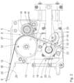
- FIGS. 2 and 3 are schematic side views of the band drive mechanism of this strapping machine indifferent positions of the strapping band.
- the strapping machine has a machine frame 1 mounted on rollers, on which is arranged a work bench 2 .
- the work bench 2 has conveyor belts (not shown), by means of which the objects 4 being strapped, such as a stack of newspapers in FIG. 1 , is transported into the strapping position on the work bench 2 .
- a turntable can also be integrated in the work bench 2 , as is found in EP 0 445 429 B1.
- a vertically upright band guide frame 6 On the work bench 2 is arranged a vertically upright band guide frame 6 , by means of which the strapping band 7 can be led as a loose loop around the object 4 on the work bench 2 .
- the strapping band 7 stored on a supply roll not otherwise depicted at the side of the machine frame 1 is shot by the band drive mechanism 5 shown only schematically in FIG. 1 underneath the work bench 2 through the welding head 3 of the strapping machine into the band guide frame 6 forming the shooting trajectory and led around it until it again arrives at the welding head 3 .
- the detector arranged there at the end of the shooting trajectory in the form of an end switch 16 detects the proper arrival of the strapping band 7 .
- the end of the band is fixed there and then the strapping band 7 is retrieved with the aid of the band drive mechanism 5 , whereupon it emerges from the band guide frame 6 and lies around the object 4 as a still un -tensioned loop.
- the band is tensioned and thus lies firmly about the object 4 .
- the band layers overlapping in the welding head 3 are heat welded, for example, and the resulting product is separated from the supplied strapping band.
- the object 4 is now strapped and can be transported away.
- FIG. 2 will explain the layout of the band drive mechanism 5 .
- the basic subassemblies are, first, the shooting and retrieval unit 8 and, secondly, the back tensioning unit 9 , which perform the above mentioned band manipulations according to their designation.
- Guide channel sections 10 , 11 , 12 are provided to form a defined transport path for the strapping band 7 through the band drive mechanism 5 .
- a first guide channel section 10 leads the strapping band 7 from the supply roll or interim storage (neither being shown) to the back tensioning unit 9 .
- a second guide channel section 11 connects the back tensioning unit 9 and the shooting and retrieval unit 8 .
- a last guide channel section 12 goes from the shooting and retrieval unit 8 in the direction of the welding head 3 and to the point of entry of the strapping band 7 into the band guide frame 6 .
- the shooting and retrieval unit 8 has a drive roller pair 13 with a roller 14 driven by a motor (not shown) and a non-driven pressure roller 15 .
- the roller 14 of the drive roller pair 13 is set turning in the proper direction via the actuation of the drive motor by a control unit (not shown) and the strapping band 7 is taken around in the band guide frame 6 until its leading end 40 with detection by the end switch 16 comes to lie in the region of the welding head 3 and is fixed there.
- the drive roller pair 13 is activated in the opposite direction and in this way the strapping band 7 is retrieved, as described above, until it is laid basically with no tension about the object 4 being strapped.
- the back tensioning unit 9 has a tension roller pair 17 with interconnected rollers 18 , 19 , which then applies a large tractive force with the aid of its drive motor (not shown) for the back tensioning of the strapping band 7 about the object 4 being strapped.
- the guide channel sections 10 , 11 are formed by web-like cheeks 20 , 21 jointly led away across the rollers 18 , 19 , which are fixed by projecting support feet 22 , 23 in a manner to be explained below in the band drive mechanism 5 .
- the rollers 18 , 19 reach through recesses in the cheeks 20 , 21 , not otherwise shown in the drawing.
- the guide channel section 12 is likewise formed by cheeks 24 , 25 on either side, the one cheek 24 being formed by the side surface of a prismatic body 26 that is roughly T-shaped in top view.
- the other cheek 25 is formed to be curved in a curved section corresponding to the outer circumference of the roller 14 by a strapping angle for the strapping band 7 and then continues in a straight section. It is formed as a side surface on a corresponding elongated prismatic body 27 .
- the triggering event is the fact that the end switch 16 does not respond in the time defined for the shooting of the strapping band 7 in the machine control unit, of say 0.2 seconds. This is a signal that the strapping band 7 has not reached the welding head 3 with its leading end 40 .
- the shooting and retrieval unit 8 is activated so that the strapping band 7 is transported back against the shooting direction E with a substantially lower retrieval speed than for the shooting process.
- the retrieval time is defined so that the strapping band 7 is pulled with certainty completely out of the shooting path and the shooting and retrieval unit 8 . In this way, the strapping band 7 stops with its leading end 40 between the latter and the back tensioning unit 9 .
- the retrieval time can also be defined variably by a kind of self-learning system, in that the retrieval time is determined by deriving the required time from the previous shooting in direct proportionality to the reduced retrieval speed.
- the control system of the strapping machine then activates the back tensioning unit 9 against its normal back tensioning direction, which is opposite the shooting direction E.
- the roller 18 of the tension roller pair 17 is set moving counterclockwise, so that the strapping band 7 is again transported in the shooting direction E from the position shown in FIG. 3 upward in the roller gap of the drive roller pair 13 of the shooting and retrieval unit 8 .
- This takes up the leading end 40 of the strapping band 7 once again.
- the drive roller 14 of the shooting and retrieval unit 8 the strapping band 7 is again shot into the band guide frame 6 .
- the drive of the back tensioning unit 9 can be deactivated once more.
Landscapes
- Engineering & Computer Science (AREA)
- Mechanical Engineering (AREA)
- Basic Packing Technique (AREA)
Abstract
Description
-
- polling the detector for detecting the leading end of the band as to a proper shooting of the strapping band in the shooting direction up till the end of the shooting trajectory,
- for an improper shooting of the strapping band, activating the shooting and retrieval unit to retrieve the strapping band with a definite retrieval speed for a defined retrieval time so that the strapping band emerges from the shooting and retrieval unit opposite the shooting direction, and
- actuating the drive of the back-tensioning unit so that the back-tensioning unit transports the strapping band back into the shooting and retrieval unit in the shooting direction.
Claims (19)
Priority Applications (1)
| Application Number | Priority Date | Filing Date | Title |
|---|---|---|---|
| US16/400,409 US11597546B2 (en) | 2011-05-11 | 2019-05-01 | Method for actuating the band driving device of a strapping machine and corresponding strapping machine |
Applications Claiming Priority (5)
| Application Number | Priority Date | Filing Date | Title |
|---|---|---|---|
| DE102011075629.9 | 2011-05-11 | ||
| DE102011075629.9A DE102011075629B4 (en) | 2011-05-11 | 2011-05-11 | Method for controlling the tape drive device of a strapping machine and corresponding strapping machine |
| PCT/EP2012/058027 WO2012152626A2 (en) | 2011-05-11 | 2012-05-02 | Method for actuating the band driving device of a strapping machine and corresponding strapping machine |
| US201314117027A | 2013-12-05 | 2013-12-05 | |
| US16/400,409 US11597546B2 (en) | 2011-05-11 | 2019-05-01 | Method for actuating the band driving device of a strapping machine and corresponding strapping machine |
Related Parent Applications (2)
| Application Number | Title | Priority Date | Filing Date |
|---|---|---|---|
| PCT/EP2012/058027 Continuation WO2012152626A2 (en) | 2011-05-11 | 2012-05-02 | Method for actuating the band driving device of a strapping machine and corresponding strapping machine |
| US14/117,027 Continuation US10322830B2 (en) | 2011-05-11 | 2012-05-02 | Method for actuating the band driving device of a strapping machine and corresponding strapping machine |
Publications (2)
| Publication Number | Publication Date |
|---|---|
| US20190256232A1 US20190256232A1 (en) | 2019-08-22 |
| US11597546B2 true US11597546B2 (en) | 2023-03-07 |
Family
ID=46044691
Family Applications (2)
| Application Number | Title | Priority Date | Filing Date |
|---|---|---|---|
| US14/117,027 Active 2035-12-31 US10322830B2 (en) | 2011-05-11 | 2012-05-02 | Method for actuating the band driving device of a strapping machine and corresponding strapping machine |
| US16/400,409 Active 2035-01-07 US11597546B2 (en) | 2011-05-11 | 2019-05-01 | Method for actuating the band driving device of a strapping machine and corresponding strapping machine |
Family Applications Before (1)
| Application Number | Title | Priority Date | Filing Date |
|---|---|---|---|
| US14/117,027 Active 2035-12-31 US10322830B2 (en) | 2011-05-11 | 2012-05-02 | Method for actuating the band driving device of a strapping machine and corresponding strapping machine |
Country Status (5)
| Country | Link |
|---|---|
| US (2) | US10322830B2 (en) |
| EP (1) | EP2707288B1 (en) |
| DE (1) | DE102011075629B4 (en) |
| PL (1) | PL2707288T3 (en) |
| WO (1) | WO2012152626A2 (en) |
Cited By (2)
| Publication number | Priority date | Publication date | Assignee | Title |
|---|---|---|---|---|
| US12240645B2 (en) | 2020-11-17 | 2025-03-04 | Signode Industrial Group Llc | Strap-feeding assembly with strap-size-adjustment features |
| US12492026B2 (en) | 2020-12-23 | 2025-12-09 | Signode Industrial Group Llc | Strap-tensioning assembly with self-energizing transitioning wheel, and strap-size-adjustment features |
Families Citing this family (14)
| Publication number | Priority date | Publication date | Assignee | Title |
|---|---|---|---|---|
| CH705743A2 (en) | 2011-11-14 | 2013-05-15 | Illinois Tool Works | Strapper. |
| CH709219A2 (en) | 2014-02-10 | 2015-08-14 | Orgapack Gmbh | Strap application of a strapping device for strapping goods with a strapping band. |
| DE102014225870A1 (en) | 2014-12-15 | 2016-06-16 | Krones Aktiengesellschaft | Strapping head and method of handling a strapping band |
| DE102014225880A1 (en) | 2014-12-15 | 2016-06-16 | Krones Aktiengesellschaft | Strapping head and method of handling a strapping band |
| USD864688S1 (en) * | 2017-03-28 | 2019-10-29 | Signode Industrial Group Llc | Strapping device |
| EP3398866A1 (en) | 2017-05-05 | 2018-11-07 | Sund Birsta AB | Feeding and tensioning unit for use in a strapping machine or wire binding machine |
| EP3670366B1 (en) * | 2018-12-21 | 2021-06-16 | Sund Birsta AB | Binding machine and method for testing the strength of a joint formed on a closed loop of an elongated binding element |
| DE102019109475A1 (en) | 2019-04-10 | 2020-10-15 | Wilhelm B a h m ü l l e r Maschinenbau Präzisionswerkzeuge GmbH | Strap strapping machine for strapping a material with a strap |
| CN110356652B (en) * | 2019-07-04 | 2024-04-19 | 苏州大喆智能科技有限公司 | Detection, stacking, bundling and conveying all-in-one machine for objects |
| CA192340S (en) * | 2019-07-22 | 2021-12-30 | Ergopack Deutschland Gmbh | Packaging machine |
| DE102019215010B4 (en) | 2019-09-30 | 2021-12-09 | Signode Industrial Group Llc | Welding head for a strapping machine and counter pressure plate that can be used in it |
| USD983245S1 (en) * | 2021-09-24 | 2023-04-11 | Dongguan Jingduan Packaging Technology Co. Ltd | Pallet strapping machine |
| DE202022102045U1 (en) * | 2022-04-14 | 2023-07-19 | Hellermanntyton Gmbh | Automatic bundling tool device, ABT, for bundling a bundle with a one-piece binder with quality monitoring |
| WO2026006078A1 (en) * | 2024-06-25 | 2026-01-02 | Signode Industrial Group Llc | Strapping machine with retraction validation |
Citations (69)
| Publication number | Priority date | Publication date | Assignee | Title |
|---|---|---|---|---|
| JPS4814577B1 (en) | 1969-06-14 | 1973-05-08 | ||
| JPH01213109A (en) | 1988-02-08 | 1989-08-25 | Nichiro Kogyo Kk | Automatic band feed trouble correcting method in arch type automatic packing machine |
| US4912912A (en) | 1987-05-30 | 1990-04-03 | Strapack Corporation | Control apparatus in strapping machine |
| US5079899A (en) * | 1990-12-19 | 1992-01-14 | Strapack Corporation | Band reel replacing and band loading method and apparatus |
| US5083412A (en) | 1990-02-09 | 1992-01-28 | Strapack Corporation | Method of removing idle strapping band for strapping machine |
| US5111634A (en) | 1990-03-08 | 1992-05-12 | Smb Schwede Maschinenbau | Packaging station for a packaging machine, in which a stack of goods is hooped with a packaging tape |
| US5287802A (en) * | 1992-12-14 | 1994-02-22 | Signode Corporation | Strap severing and ejecting mechanism for strapping machine |
| US5299407A (en) | 1991-11-26 | 1994-04-05 | Signode Bernpak Gmbh | Process and device for avoiding strapping-caused downtime on machine for strapping packages |
| US5333438A (en) | 1992-11-06 | 1994-08-02 | Signode Corporation | Dual coil power strapping machine |
| US5379576A (en) | 1992-06-10 | 1995-01-10 | Strapack Corporation | Band feeding and tightening apparatus for packing machine |
| US5560187A (en) * | 1993-12-28 | 1996-10-01 | Kioritz Corporation | Strapping machine |
| DE19602579A1 (en) | 1996-01-25 | 1997-07-31 | Smb Schwede Maschinenbau Gmbh | Strap tensioner for strapping machine, e.g. for tying up stacks of magazines or cardboard boxes |
| DE29822344U1 (en) | 1998-12-03 | 1999-03-18 | GIN DAH ENTERPRISES CORP., Tu-Cheng, Taipeh | Belt guide device for an automatic packaging device |
| US6032440A (en) | 1997-07-16 | 2000-03-07 | Mashinenfabrik Gerd Mosca Gmbh | Tensioning device for hoop-casing machines |
| US6041698A (en) | 1999-03-17 | 2000-03-28 | Tekpak Corporation | Guide band packaging machine |
| US6334563B1 (en) | 1999-05-05 | 2002-01-01 | Smb Schwede Maschinenbau Gmbh | Retensioning device for strapping machines |
| US6401764B1 (en) | 2000-03-27 | 2002-06-11 | Illinois Tool Works Inc. | Gripper for strapping machine |
| US6405917B1 (en) | 1999-08-11 | 2002-06-18 | Smb Schwee Maschinenbau Gmbh | Welding head for a looping machine |
| US20020089110A1 (en) * | 2000-12-22 | 2002-07-11 | Packaging Progressions, Inc | Paper jam detector for automatic food processing line |
| US6463848B1 (en) | 2000-05-08 | 2002-10-15 | Illinois Tool Works Inc. | Strapper with improved winding and cutting assembly |
| US6478065B1 (en) | 2000-06-26 | 2002-11-12 | Illinois Tool Works Inc. | Strapping machine with improved access doors |
| US20030010225A1 (en) | 2001-07-12 | 2003-01-16 | Pearson Timothy B. | Strapping machine with easy access and feed guides |
| US6532722B2 (en) | 2001-07-18 | 2003-03-18 | Illinois Tool Works | Strapping machine weld head with vibrating anvil |
| US6543341B2 (en) * | 2001-07-12 | 2003-04-08 | Illinois Tool Works, Inc. | Strapping machine with strapping head sensor |
| US6571531B2 (en) * | 2001-04-02 | 2003-06-03 | Illinois Tool Works, Inc. | Strap detector assembly |
| US6575086B2 (en) * | 2001-07-12 | 2003-06-10 | Illinois Tool Works, Inc. | Strapping machine strapping head with pivoting anvil |
| US6584892B2 (en) | 2001-07-12 | 2003-07-01 | Illinois Tool Works, Inc. | Strapping machine with modular heads |
| US6607158B1 (en) | 1999-07-26 | 2003-08-19 | Illinois Tool Works, Inc. | Unwinding apparatus |
| US6629398B2 (en) | 2001-07-12 | 2003-10-07 | Illinois Tool Works, Inc. | Strapping machine with improved refeed |
| US6708606B1 (en) | 2002-10-31 | 2004-03-23 | Illinois Tool Works, Inc. | Strapper with improved winder |
| US20040060259A1 (en) | 2002-10-01 | 2004-04-01 | Strapack Corporation | Band refeeding method in banding packing machine and banding packing machine having refeeding mechanism |
| WO2004039676A1 (en) | 2002-10-31 | 2004-05-13 | Endra B.V. | Device for applying at least two straps around a packet |
| US6820402B1 (en) | 2003-06-20 | 2004-11-23 | Illinois Tool Works, Inc. | Strapping machine with pivoting dispenser loading |
| EP1489009A1 (en) | 2003-06-17 | 2004-12-22 | Illinois Tool Works Inc. | Improved strap chute opening device for a strapping machine |
| EP1489005A2 (en) | 2003-06-20 | 2004-12-22 | Illinois Tool Works Inc. | Strapping machine with strap feeding and tensionning system with automatic refeed |
| US6848241B2 (en) | 2003-05-02 | 2005-02-01 | Illinois Tool Works, Inc. | Anvil and vibrator pad support for strapping machine |
| US6857252B2 (en) | 2003-06-20 | 2005-02-22 | Illinois Tool Works, Inc. | Strapping machine with strap path access guide |
| US6871584B2 (en) | 2003-05-28 | 2005-03-29 | Illinois Tool Works, Inc. | Strapping machine with self cleaning feed limit switch components |
| US6904841B2 (en) | 2003-06-17 | 2005-06-14 | Illinois Tool Works, Inc. | Strapping machine with adjustable height work surface |
| US6911799B2 (en) | 2003-04-25 | 2005-06-28 | Illinois Tool Works, Inc. | Strapping machine weld motor control system |
| US6923113B2 (en) | 2002-11-27 | 2005-08-02 | Illinois Tool Works, Inc. | Strapping machine with paddle formed strap path |
| US6935227B2 (en) | 2003-05-30 | 2005-08-30 | Illinois Tool Works, Inc. | Single pin gripper assembly for strapping machine head |
| US6945164B2 (en) | 2003-06-17 | 2005-09-20 | Illinois Tool Works, Inc. | Strapping machine with pivoting weld blade |
| US6955119B2 (en) | 2003-06-17 | 2005-10-18 | Illinois Tool Works, Inc. | Strapping machine with pivotal work surfaces having integral conveyors |
| US6962109B2 (en) | 2003-06-17 | 2005-11-08 | Illinois Tool Works, Inc. | Strapping machine with automatic chute opening system |
| US7007597B1 (en) | 2004-09-27 | 2006-03-07 | Illinois Tool Works, Inc. | Vibrator assembly for strapping machine weld head |
| US7121193B2 (en) | 2005-02-04 | 2006-10-17 | Illinois Tool Works Inc. | Flexible strap feed guide for overhead strapper |
| US7234394B1 (en) | 2006-04-03 | 2007-06-26 | Illinois Tool Works Inc. | Chute corner with spring loaded chute liner |
| US7237478B1 (en) | 2006-08-02 | 2007-07-03 | Illinois Tool Works Inc. | Asymmetrical strap chute and release system |
| US7270055B1 (en) | 2006-11-10 | 2007-09-18 | Illnois Tool Works, Inc. | Centrifugal boost wheel for strapping machine |
| US7377213B1 (en) | 2007-09-07 | 2008-05-27 | Illinois Tool Works Inc. | Strapping machine with improved tension, seal and feed arrangement |
| JP4095817B2 (en) | 2002-03-26 | 2008-06-04 | シグノード株式会社 | Bundling device |
| US7383765B2 (en) | 2006-05-03 | 2008-06-10 | Illinois Tool Works Inc. | Strapping machine |
| US7395754B1 (en) | 2007-12-19 | 2008-07-08 | Illinois Tool Works Inc. | Quick access guide with integrated strap chute opener |
| US7428867B1 (en) | 2007-09-07 | 2008-09-30 | Illinois Tool Works Inc. | Self-energizing gripper for strapping machine |
| US7428865B1 (en) | 2007-09-24 | 2008-09-30 | Illinois Tool Works Inc. | Press-type strapping machine |
| US7454877B2 (en) | 2006-09-26 | 2008-11-25 | Illinois Tool Works Inc. | Tension control system and method for tensioning a strapping material around a load in a strapping machine |
| JP4366208B2 (en) | 2004-02-18 | 2009-11-18 | シグノード株式会社 | Bundling device |
| JP4405220B2 (en) | 2003-09-26 | 2010-01-27 | シグノード株式会社 | Bundling device for slit coil |
| US7681496B2 (en) | 2005-12-28 | 2010-03-23 | Illinois Tool Works Inc. | Method and device for strapping goods |
| US7798060B2 (en) | 2007-10-24 | 2010-09-21 | Illinois Tool Works Inc. | Modular strap dispenser with feed motor |
| US7861649B2 (en) | 2008-12-19 | 2011-01-04 | Illinois Tool Works Inc. | Self-adjusting stripper pin for strapping machine strap chute |
| JP4627598B2 (en) | 2001-02-05 | 2011-02-09 | シグノード株式会社 | Bundling device |
| JP4814577B2 (en) | 2005-08-17 | 2011-11-16 | シグノード株式会社 | Bundling device |
| US8516780B2 (en) | 2001-09-20 | 2013-08-27 | Endra B.V. | Method and device for strapping one or more packets with a band with label means |
| JP5298088B2 (en) | 2010-08-19 | 2013-09-25 | シグノード株式会社 | Bundling device |
| US8607695B2 (en) | 2009-12-23 | 2013-12-17 | Smb Schwede Maschinenbnau Gmbh | Strap driving device for a strapping machine |
| US8904925B2 (en) | 2010-06-22 | 2014-12-09 | Illinois Tool Works Inc. | Modular strapping head with heat blade |
| US9296501B2 (en) * | 2010-07-22 | 2016-03-29 | Signode Industrial Group Llc | Modular strap feeder with motor for indexing and gripping |
-
2011
- 2011-05-11 DE DE102011075629.9A patent/DE102011075629B4/en active Active
-
2012
- 2012-05-02 US US14/117,027 patent/US10322830B2/en active Active
- 2012-05-02 EP EP12719363.9A patent/EP2707288B1/en active Active
- 2012-05-02 PL PL12719363T patent/PL2707288T3/en unknown
- 2012-05-02 WO PCT/EP2012/058027 patent/WO2012152626A2/en not_active Ceased
-
2019
- 2019-05-01 US US16/400,409 patent/US11597546B2/en active Active
Patent Citations (76)
| Publication number | Priority date | Publication date | Assignee | Title |
|---|---|---|---|---|
| JPS4814577B1 (en) | 1969-06-14 | 1973-05-08 | ||
| US4912912A (en) | 1987-05-30 | 1990-04-03 | Strapack Corporation | Control apparatus in strapping machine |
| JPH01213109A (en) | 1988-02-08 | 1989-08-25 | Nichiro Kogyo Kk | Automatic band feed trouble correcting method in arch type automatic packing machine |
| US5083412A (en) | 1990-02-09 | 1992-01-28 | Strapack Corporation | Method of removing idle strapping band for strapping machine |
| US5111634A (en) | 1990-03-08 | 1992-05-12 | Smb Schwede Maschinenbau | Packaging station for a packaging machine, in which a stack of goods is hooped with a packaging tape |
| US5079899A (en) * | 1990-12-19 | 1992-01-14 | Strapack Corporation | Band reel replacing and band loading method and apparatus |
| US5299407A (en) | 1991-11-26 | 1994-04-05 | Signode Bernpak Gmbh | Process and device for avoiding strapping-caused downtime on machine for strapping packages |
| US5379576A (en) | 1992-06-10 | 1995-01-10 | Strapack Corporation | Band feeding and tightening apparatus for packing machine |
| US5333438A (en) | 1992-11-06 | 1994-08-02 | Signode Corporation | Dual coil power strapping machine |
| US5287802A (en) * | 1992-12-14 | 1994-02-22 | Signode Corporation | Strap severing and ejecting mechanism for strapping machine |
| US5560187A (en) * | 1993-12-28 | 1996-10-01 | Kioritz Corporation | Strapping machine |
| US5791238A (en) | 1996-01-25 | 1998-08-11 | Smb Schwede Maschinenbau Gmbh | Looping strap tensioning device |
| DE19602579A1 (en) | 1996-01-25 | 1997-07-31 | Smb Schwede Maschinenbau Gmbh | Strap tensioner for strapping machine, e.g. for tying up stacks of magazines or cardboard boxes |
| US6032440A (en) | 1997-07-16 | 2000-03-07 | Mashinenfabrik Gerd Mosca Gmbh | Tensioning device for hoop-casing machines |
| DE29822344U1 (en) | 1998-12-03 | 1999-03-18 | GIN DAH ENTERPRISES CORP., Tu-Cheng, Taipeh | Belt guide device for an automatic packaging device |
| US6173557B1 (en) | 1998-12-03 | 2001-01-16 | Gin Dan Enterprises Corp. | Tape-leading mechanism for an automatic packer |
| US6041698A (en) | 1999-03-17 | 2000-03-28 | Tekpak Corporation | Guide band packaging machine |
| US6334563B1 (en) | 1999-05-05 | 2002-01-01 | Smb Schwede Maschinenbau Gmbh | Retensioning device for strapping machines |
| US6607158B1 (en) | 1999-07-26 | 2003-08-19 | Illinois Tool Works, Inc. | Unwinding apparatus |
| US6405917B1 (en) | 1999-08-11 | 2002-06-18 | Smb Schwee Maschinenbau Gmbh | Welding head for a looping machine |
| US6401764B1 (en) | 2000-03-27 | 2002-06-11 | Illinois Tool Works Inc. | Gripper for strapping machine |
| US6463848B1 (en) | 2000-05-08 | 2002-10-15 | Illinois Tool Works Inc. | Strapper with improved winding and cutting assembly |
| US6478065B1 (en) | 2000-06-26 | 2002-11-12 | Illinois Tool Works Inc. | Strapping machine with improved access doors |
| US20020089110A1 (en) * | 2000-12-22 | 2002-07-11 | Packaging Progressions, Inc | Paper jam detector for automatic food processing line |
| JP4627598B2 (en) | 2001-02-05 | 2011-02-09 | シグノード株式会社 | Bundling device |
| US6571531B2 (en) * | 2001-04-02 | 2003-06-03 | Illinois Tool Works, Inc. | Strap detector assembly |
| US6543341B2 (en) * | 2001-07-12 | 2003-04-08 | Illinois Tool Works, Inc. | Strapping machine with strapping head sensor |
| US6584892B2 (en) | 2001-07-12 | 2003-07-01 | Illinois Tool Works, Inc. | Strapping machine with modular heads |
| US6629398B2 (en) | 2001-07-12 | 2003-10-07 | Illinois Tool Works, Inc. | Strapping machine with improved refeed |
| US20030010225A1 (en) | 2001-07-12 | 2003-01-16 | Pearson Timothy B. | Strapping machine with easy access and feed guides |
| US6575086B2 (en) * | 2001-07-12 | 2003-06-10 | Illinois Tool Works, Inc. | Strapping machine strapping head with pivoting anvil |
| US6745677B2 (en) | 2001-07-12 | 2004-06-08 | Illinois Tool Works, Inc. | Strapping machine with easy access and feed guides |
| US6532722B2 (en) | 2001-07-18 | 2003-03-18 | Illinois Tool Works | Strapping machine weld head with vibrating anvil |
| US8516780B2 (en) | 2001-09-20 | 2013-08-27 | Endra B.V. | Method and device for strapping one or more packets with a band with label means |
| JP4095817B2 (en) | 2002-03-26 | 2008-06-04 | シグノード株式会社 | Bundling device |
| US20040060259A1 (en) | 2002-10-01 | 2004-04-01 | Strapack Corporation | Band refeeding method in banding packing machine and banding packing machine having refeeding mechanism |
| DE60318160T2 (en) | 2002-10-01 | 2008-12-04 | Strapack Corp. | Method for re-feeding strapping bands and strapping machine |
| US6848239B2 (en) * | 2002-10-01 | 2005-02-01 | Strapack Corporation | Band refeeding method in banding packing machine and banding packing machine having refeeding mechanism |
| WO2004039676A1 (en) | 2002-10-31 | 2004-05-13 | Endra B.V. | Device for applying at least two straps around a packet |
| US6708606B1 (en) | 2002-10-31 | 2004-03-23 | Illinois Tool Works, Inc. | Strapper with improved winder |
| US6923113B2 (en) | 2002-11-27 | 2005-08-02 | Illinois Tool Works, Inc. | Strapping machine with paddle formed strap path |
| US6911799B2 (en) | 2003-04-25 | 2005-06-28 | Illinois Tool Works, Inc. | Strapping machine weld motor control system |
| US6848241B2 (en) | 2003-05-02 | 2005-02-01 | Illinois Tool Works, Inc. | Anvil and vibrator pad support for strapping machine |
| US6871584B2 (en) | 2003-05-28 | 2005-03-29 | Illinois Tool Works, Inc. | Strapping machine with self cleaning feed limit switch components |
| US6935227B2 (en) | 2003-05-30 | 2005-08-30 | Illinois Tool Works, Inc. | Single pin gripper assembly for strapping machine head |
| US6904841B2 (en) | 2003-06-17 | 2005-06-14 | Illinois Tool Works, Inc. | Strapping machine with adjustable height work surface |
| EP1489009A1 (en) | 2003-06-17 | 2004-12-22 | Illinois Tool Works Inc. | Improved strap chute opening device for a strapping machine |
| US6945164B2 (en) | 2003-06-17 | 2005-09-20 | Illinois Tool Works, Inc. | Strapping machine with pivoting weld blade |
| US6955119B2 (en) | 2003-06-17 | 2005-10-18 | Illinois Tool Works, Inc. | Strapping machine with pivotal work surfaces having integral conveyors |
| US6962109B2 (en) | 2003-06-17 | 2005-11-08 | Illinois Tool Works, Inc. | Strapping machine with automatic chute opening system |
| EP1489005A2 (en) | 2003-06-20 | 2004-12-22 | Illinois Tool Works Inc. | Strapping machine with strap feeding and tensionning system with automatic refeed |
| US6857252B2 (en) | 2003-06-20 | 2005-02-22 | Illinois Tool Works, Inc. | Strapping machine with strap path access guide |
| US6820402B1 (en) | 2003-06-20 | 2004-11-23 | Illinois Tool Works, Inc. | Strapping machine with pivoting dispenser loading |
| US20040255552A1 (en) * | 2003-06-20 | 2004-12-23 | Illinois Tool Works, Inc. | Strapping machine with strap feeding and tensioning system with automatic refeed |
| US6981353B2 (en) | 2003-06-20 | 2006-01-03 | Illinois Tool Works, Inc. | Strapping machine with strap feeding and tensioning system with automatic refeed |
| JP4405220B2 (en) | 2003-09-26 | 2010-01-27 | シグノード株式会社 | Bundling device for slit coil |
| JP4366208B2 (en) | 2004-02-18 | 2009-11-18 | シグノード株式会社 | Bundling device |
| US7007597B1 (en) | 2004-09-27 | 2006-03-07 | Illinois Tool Works, Inc. | Vibrator assembly for strapping machine weld head |
| US7121193B2 (en) | 2005-02-04 | 2006-10-17 | Illinois Tool Works Inc. | Flexible strap feed guide for overhead strapper |
| JP4814577B2 (en) | 2005-08-17 | 2011-11-16 | シグノード株式会社 | Bundling device |
| US7681496B2 (en) | 2005-12-28 | 2010-03-23 | Illinois Tool Works Inc. | Method and device for strapping goods |
| US7234394B1 (en) | 2006-04-03 | 2007-06-26 | Illinois Tool Works Inc. | Chute corner with spring loaded chute liner |
| US7383765B2 (en) | 2006-05-03 | 2008-06-10 | Illinois Tool Works Inc. | Strapping machine |
| US7237478B1 (en) | 2006-08-02 | 2007-07-03 | Illinois Tool Works Inc. | Asymmetrical strap chute and release system |
| US7454877B2 (en) | 2006-09-26 | 2008-11-25 | Illinois Tool Works Inc. | Tension control system and method for tensioning a strapping material around a load in a strapping machine |
| US7270055B1 (en) | 2006-11-10 | 2007-09-18 | Illnois Tool Works, Inc. | Centrifugal boost wheel for strapping machine |
| US7377213B1 (en) | 2007-09-07 | 2008-05-27 | Illinois Tool Works Inc. | Strapping machine with improved tension, seal and feed arrangement |
| US7428867B1 (en) | 2007-09-07 | 2008-09-30 | Illinois Tool Works Inc. | Self-energizing gripper for strapping machine |
| US7428865B1 (en) | 2007-09-24 | 2008-09-30 | Illinois Tool Works Inc. | Press-type strapping machine |
| US7798060B2 (en) | 2007-10-24 | 2010-09-21 | Illinois Tool Works Inc. | Modular strap dispenser with feed motor |
| US7395754B1 (en) | 2007-12-19 | 2008-07-08 | Illinois Tool Works Inc. | Quick access guide with integrated strap chute opener |
| US7861649B2 (en) | 2008-12-19 | 2011-01-04 | Illinois Tool Works Inc. | Self-adjusting stripper pin for strapping machine strap chute |
| US8607695B2 (en) | 2009-12-23 | 2013-12-17 | Smb Schwede Maschinenbnau Gmbh | Strap driving device for a strapping machine |
| US8904925B2 (en) | 2010-06-22 | 2014-12-09 | Illinois Tool Works Inc. | Modular strapping head with heat blade |
| US9296501B2 (en) * | 2010-07-22 | 2016-03-29 | Signode Industrial Group Llc | Modular strap feeder with motor for indexing and gripping |
| JP5298088B2 (en) | 2010-08-19 | 2013-09-25 | シグノード株式会社 | Bundling device |
Non-Patent Citations (5)
| Title |
|---|
| "Annotated Applicant Admitted Prior Art (AAPA), excerpt of pp. 1-4 of the specification", in Non-Final Office Action in U.S. Appl. No. 14/117,027, dated Nov. 3, 2017. |
| "First Office Action", from corresponding European Patent Application No. EP 12719363.9 (with English translation), dated Oct. 14, 2016. |
| "Office Action", from corresponding German Patent Application No. DE 102011075629.9 (with English translation), dated Dec. 2, 2011. |
| "Second Office Action", from corresponding European Patent Application No. EP 12719363.9 (with English translation), dated Nov. 23, 2017. |
| European Patent Office, as International Searching Authority, International Search Report and Written Opinion (in German with English Translation) dated Nov. 19, 2012 in Application No. PCT/EP2012/058027 (13 pages). |
Cited By (2)
| Publication number | Priority date | Publication date | Assignee | Title |
|---|---|---|---|---|
| US12240645B2 (en) | 2020-11-17 | 2025-03-04 | Signode Industrial Group Llc | Strap-feeding assembly with strap-size-adjustment features |
| US12492026B2 (en) | 2020-12-23 | 2025-12-09 | Signode Industrial Group Llc | Strap-tensioning assembly with self-energizing transitioning wheel, and strap-size-adjustment features |
Also Published As
| Publication number | Publication date |
|---|---|
| WO2012152626A3 (en) | 2013-01-10 |
| DE102011075629B4 (en) | 2016-09-15 |
| US20190256232A1 (en) | 2019-08-22 |
| EP2707288B1 (en) | 2019-04-17 |
| EP2707288A2 (en) | 2014-03-19 |
| WO2012152626A2 (en) | 2012-11-15 |
| US20140083310A1 (en) | 2014-03-27 |
| DE102011075629A1 (en) | 2012-11-15 |
| PL2707288T3 (en) | 2019-12-31 |
| US10322830B2 (en) | 2019-06-18 |
Similar Documents
| Publication | Publication Date | Title |
|---|---|---|
| US11597546B2 (en) | Method for actuating the band driving device of a strapping machine and corresponding strapping machine | |
| US5299407A (en) | Process and device for avoiding strapping-caused downtime on machine for strapping packages | |
| US5079899A (en) | Band reel replacing and band loading method and apparatus | |
| JP5846725B2 (en) | Intermittent film transport device | |
| EP2325087B1 (en) | Back-to-back bundle strapping machine | |
| US7540125B2 (en) | Bursting apparatus and method | |
| CN105691689A (en) | Strapping head and method of handling a strapping band | |
| US20080211168A1 (en) | Apparatus and method for separating flat articles | |
| EP1405791B1 (en) | Band refeeding method and banding machine | |
| EP3795517B1 (en) | Rubber sheet member supply device and method | |
| CN104787413B (en) | Equipment for supplying label sleeves | |
| JPH0725526A (en) | Strip material-replacing method for manufacturing machine | |
| TW201628957A (en) | Tension controller and conveyer | |
| JP2019517942A (en) | Apparatus and method for converting a sheet into a continuous strip | |
| NL2019239B1 (en) | Tape sealer for winding adhesive tape around an object | |
| JP4485220B2 (en) | Automatic film feeder for deep drawing packaging machine | |
| EP3556228B2 (en) | Machine and method for processing a web of material for the tobacco industry | |
| US6607158B1 (en) | Unwinding apparatus | |
| US7401777B2 (en) | Apparatus for supplying a shingled or overlapping sheet stream | |
| US11827395B2 (en) | Automatic-strap-feeding system for feeding strap into a strapping machine | |
| JP2021062936A (en) | Tape applicator | |
| US20250234962A1 (en) | Intelligent digital shoelace end wrapping machine | |
| JP2504516B2 (en) | Direct material following supply device | |
| JPH09183419A (en) | Film switching and sending device in stretch film packing machine | |
| KR101951944B1 (en) | Paper supply apparatus |
Legal Events
| Date | Code | Title | Description |
|---|---|---|---|
| AS | Assignment |
Owner name: SMB SCHWEDE MASCHINEBAU GMBH, GERMANY Free format text: ASSIGNMENT OF ASSIGNORS INTEREST;ASSIGNORS:HOEHN, JUERGEN;WITZGALL, JOCHEN;SCHOEDEL, JUERGEN;SIGNING DATES FROM 20131112 TO 20131121;REEL/FRAME:049053/0828 |
|
| FEPP | Fee payment procedure |
Free format text: ENTITY STATUS SET TO UNDISCOUNTED (ORIGINAL EVENT CODE: BIG.); ENTITY STATUS OF PATENT OWNER: LARGE ENTITY |
|
| STPP | Information on status: patent application and granting procedure in general |
Free format text: NON FINAL ACTION MAILED |
|
| STPP | Information on status: patent application and granting procedure in general |
Free format text: RESPONSE TO NON-FINAL OFFICE ACTION ENTERED AND FORWARDED TO EXAMINER |
|
| STPP | Information on status: patent application and granting procedure in general |
Free format text: NOTICE OF ALLOWANCE MAILED -- APPLICATION RECEIVED IN OFFICE OF PUBLICATIONS |
|
| AS | Assignment |
Owner name: SIGNODE PACKAGING SYSTEMS GMBH, GERMANY Free format text: CHANGE OF NAME;ASSIGNOR:SPG PACKAGING SYSTEMS GMBH;REEL/FRAME:062543/0001 Effective date: 20210728 Owner name: SPG PACKAGING SYSTEMS GMBH, GERMANY Free format text: MERGER;ASSIGNOR:SMB SCHWEDE MASCHINENBAU GMBH;REEL/FRAME:062542/0663 Effective date: 20210101 |
|
| STCF | Information on status: patent grant |
Free format text: PATENTED CASE |