US11568698B2 - Media storage bin and method - Google Patents
Media storage bin and method Download PDFInfo
- Publication number
- US11568698B2 US11568698B2 US17/147,076 US202117147076A US11568698B2 US 11568698 B2 US11568698 B2 US 11568698B2 US 202117147076 A US202117147076 A US 202117147076A US 11568698 B2 US11568698 B2 US 11568698B2
- Authority
- US
- United States
- Prior art keywords
- base plate
- motor
- move
- guide member
- storage bin
- Prior art date
- Legal status (The legal status is an assumption and is not a legal conclusion. Google has not performed a legal analysis and makes no representation as to the accuracy of the status listed.)
- Active, expires
Links
- 238000000034 method Methods 0.000 title claims description 7
- 238000003780 insertion Methods 0.000 claims description 5
- 230000037431 insertion Effects 0.000 claims description 5
- 238000007906 compression Methods 0.000 description 6
- 230000006835 compression Effects 0.000 description 4
- 238000010586 diagram Methods 0.000 description 2
- 230000001010 compromised effect Effects 0.000 description 1
- 238000012986 modification Methods 0.000 description 1
- 230000004048 modification Effects 0.000 description 1
Images


Classifications
-
- B—PERFORMING OPERATIONS; TRANSPORTING
- B65—CONVEYING; PACKING; STORING; HANDLING THIN OR FILAMENTARY MATERIAL
- B65H—HANDLING THIN OR FILAMENTARY MATERIAL, e.g. SHEETS, WEBS, CABLES
- B65H31/00—Pile receivers
- B65H31/04—Pile receivers with movable end support arranged to recede as pile accumulates
- B65H31/08—Pile receivers with movable end support arranged to recede as pile accumulates the articles being piled one above another
- B65H31/10—Pile receivers with movable end support arranged to recede as pile accumulates the articles being piled one above another and applied at the top of the pile
-
- G—PHYSICS
- G07—CHECKING-DEVICES
- G07D—HANDLING OF COINS OR VALUABLE PAPERS, e.g. TESTING, SORTING BY DENOMINATIONS, COUNTING, DISPENSING, CHANGING OR DEPOSITING
- G07D11/00—Devices accepting coins; Devices accepting, dispensing, sorting or counting valuable papers
- G07D11/10—Mechanical details
- G07D11/16—Handling of valuable papers
- G07D11/175—Flattening, e.g. straightening out folds
-
- B—PERFORMING OPERATIONS; TRANSPORTING
- B65—CONVEYING; PACKING; STORING; HANDLING THIN OR FILAMENTARY MATERIAL
- B65H—HANDLING THIN OR FILAMENTARY MATERIAL, e.g. SHEETS, WEBS, CABLES
- B65H29/00—Delivering or advancing articles from machines; Advancing articles to or into piles
- B65H29/52—Stationary guides or smoothers
-
- B—PERFORMING OPERATIONS; TRANSPORTING
- B65—CONVEYING; PACKING; STORING; HANDLING THIN OR FILAMENTARY MATERIAL
- B65H—HANDLING THIN OR FILAMENTARY MATERIAL, e.g. SHEETS, WEBS, CABLES
- B65H31/00—Pile receivers
- B65H31/04—Pile receivers with movable end support arranged to recede as pile accumulates
- B65H31/12—Devices relieving the weight of the pile or permitting or effecting movement of the pile end support during piling
- B65H31/18—Positively-acting mechanical devices
-
- B—PERFORMING OPERATIONS; TRANSPORTING
- B65—CONVEYING; PACKING; STORING; HANDLING THIN OR FILAMENTARY MATERIAL
- B65H—HANDLING THIN OR FILAMENTARY MATERIAL, e.g. SHEETS, WEBS, CABLES
- B65H31/00—Pile receivers
- B65H31/26—Auxiliary devices for retaining articles in the pile
-
- B—PERFORMING OPERATIONS; TRANSPORTING
- B65—CONVEYING; PACKING; STORING; HANDLING THIN OR FILAMENTARY MATERIAL
- B65H—HANDLING THIN OR FILAMENTARY MATERIAL, e.g. SHEETS, WEBS, CABLES
- B65H43/00—Use of control, checking, or safety devices, e.g. automatic devices comprising an element for sensing a variable
- B65H43/06—Use of control, checking, or safety devices, e.g. automatic devices comprising an element for sensing a variable detecting, or responding to, completion of pile
-
- B—PERFORMING OPERATIONS; TRANSPORTING
- B65—CONVEYING; PACKING; STORING; HANDLING THIN OR FILAMENTARY MATERIAL
- B65H—HANDLING THIN OR FILAMENTARY MATERIAL, e.g. SHEETS, WEBS, CABLES
- B65H5/00—Feeding articles separated from piles; Feeding articles to machines
- B65H5/36—Article guides or smoothers, e.g. movable in operation
-
- G—PHYSICS
- G07—CHECKING-DEVICES
- G07D—HANDLING OF COINS OR VALUABLE PAPERS, e.g. TESTING, SORTING BY DENOMINATIONS, COUNTING, DISPENSING, CHANGING OR DEPOSITING
- G07D11/00—Devices accepting coins; Devices accepting, dispensing, sorting or counting valuable papers
- G07D11/20—Controlling or monitoring the operation of devices; Data handling
- G07D11/22—Means for sensing or detection
-
- B—PERFORMING OPERATIONS; TRANSPORTING
- B65—CONVEYING; PACKING; STORING; HANDLING THIN OR FILAMENTARY MATERIAL
- B65H—HANDLING THIN OR FILAMENTARY MATERIAL, e.g. SHEETS, WEBS, CABLES
- B65H2301/00—Handling processes for sheets or webs
- B65H2301/40—Type of handling process
- B65H2301/42—Piling, depiling, handling piles
- B65H2301/422—Handling piles, sets or stacks of articles
- B65H2301/4223—Pressing piles
-
- B—PERFORMING OPERATIONS; TRANSPORTING
- B65—CONVEYING; PACKING; STORING; HANDLING THIN OR FILAMENTARY MATERIAL
- B65H—HANDLING THIN OR FILAMENTARY MATERIAL, e.g. SHEETS, WEBS, CABLES
- B65H2301/00—Handling processes for sheets or webs
- B65H2301/50—Auxiliary process performed during handling process
- B65H2301/51—Modifying a characteristic of handled material
- B65H2301/512—Changing form of handled material
- B65H2301/5123—Compressing, i.e. diminishing thickness
- B65H2301/51232—Compressing, i.e. diminishing thickness for flattening
-
- B—PERFORMING OPERATIONS; TRANSPORTING
- B65—CONVEYING; PACKING; STORING; HANDLING THIN OR FILAMENTARY MATERIAL
- B65H—HANDLING THIN OR FILAMENTARY MATERIAL, e.g. SHEETS, WEBS, CABLES
- B65H2404/00—Parts for transporting or guiding the handled material
- B65H2404/60—Other elements in face contact with handled material
- B65H2404/63—Oscillating, pivoting around an axis parallel to face of material, e.g. diverting means
-
- B—PERFORMING OPERATIONS; TRANSPORTING
- B65—CONVEYING; PACKING; STORING; HANDLING THIN OR FILAMENTARY MATERIAL
- B65H—HANDLING THIN OR FILAMENTARY MATERIAL, e.g. SHEETS, WEBS, CABLES
- B65H2404/00—Parts for transporting or guiding the handled material
- B65H2404/60—Other elements in face contact with handled material
- B65H2404/64—Other elements in face contact with handled material reciprocating perpendicularly to face of material, e.g. pushing means
-
- B—PERFORMING OPERATIONS; TRANSPORTING
- B65—CONVEYING; PACKING; STORING; HANDLING THIN OR FILAMENTARY MATERIAL
- B65H—HANDLING THIN OR FILAMENTARY MATERIAL, e.g. SHEETS, WEBS, CABLES
- B65H2701/00—Handled material; Storage means
- B65H2701/10—Handled articles or webs
- B65H2701/18—Form of handled article or web
- B65H2701/182—Piled package
-
- B—PERFORMING OPERATIONS; TRANSPORTING
- B65—CONVEYING; PACKING; STORING; HANDLING THIN OR FILAMENTARY MATERIAL
- B65H—HANDLING THIN OR FILAMENTARY MATERIAL, e.g. SHEETS, WEBS, CABLES
- B65H2701/00—Handled material; Storage means
- B65H2701/10—Handled articles or webs
- B65H2701/19—Specific article or web
- B65H2701/1912—Banknotes, bills and cheques or the like
Definitions
- This disclosure relates generally to a media storage bin and method for a self-service terminal and more particularly to a media storage bin that is adapted to increase its internal capacity by compressing media loaded therein.
- Self-service terminals such as automatic teller machines, may include one or more bins for receiving media items. These media items may include, for example, checks or cash (banknotes) for deposit. When the deposited media items are in good condition, the media items stack neatly in the bin and allow the full bin capacity to be consistently reached. However, when the deposited media items are not in good condition, i.e., worn or with heavy creases or folds, the media items can deform, e.g., folding or curling in a manner that would require more horizontal space than a non-deformed media item, upon insertion into the bin and stacked onto a previously inserted media item. This causes the deformed media item (or items) to take up too much bin volume and significantly reduces the capacity of the bin—requiring, inter alia, more frequent service visits to empty the bin.
- FIG. 1 is a side view of a media storage bin according to the present disclosure
- FIG. 2 is a block diagram of a motor control system for the media storage bin of FIG. 1 ;
- FIG. 3 is a flowchart showing the operation of the media storage bin of FIG. 1 ;
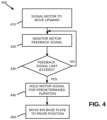
- FIG. 4 is a flowchart showing the compression cycle step of FIG. 3 .
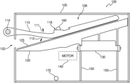
- a media storage bin 100 for use with a self-service terminal is formed by an enclosure 105 that has an internal cavity 108 .
- Media storage bin 100 receives media items 125 (e.g., checks or banknotes) via a slot 122 after such items are deposited into the self-service terminal by a customer.
- Media storage bin 100 has a guide member 110 for directing the inserted media items 125 downward onto a base plate 120 .
- Guide member 110 includes a hinge 114 that is mounted at a first end to a structural member (not shown) mounted outside of enclosure 105 via apertures in a wall of the enclosure 105 .
- Guide member 110 has a second free end extending at least partially across a width of enclosure 105 .
- hinge 114 may be mounted inside enclosure 105 to a structural member extending from the wall of enclosure 105 .
- guide member 110 freely rotates (pivots) upward as shown by arrow 111 or downward as shown by arrow 112 around a central axis of hinge 114 .
- Guide member 110 includes a flag portion 118 which interacts with an upper sensor 160 mounted on an inner wall of enclosure 105 .
- Upper sensor 160 is preferably a reflective sensor which provides an output signal when it detects a change in light at its input, and signals when guide member 110 reaches an upper limit of travel within the enclosure 105 , i.e., when flag portion 118 moves in front of upper sensor 160 as guide member 110 rotates upward as shown by arrow 111 .
- the base plate 120 is within the internal cavity 108 and is arranged to hold a stack of media items 125 (e.g., checks or banknotes) inserted into media storage bin 100 via the slot 122 on a top surface thereof.
- Base plate 120 is coupled to a cross-member 130 .
- Cross-member 130 is coupled to a motor 140 positioned outside the enclosure 105 via slots 150 in a wall of enclosure 105 so that cross-member 130 and base plate 120 can be controllably moved up and down vertically within enclosure 105 , as discussed below with respect to FIGS. 2 and 3 .
- a lower sensor 170 mounted on an inner wall of enclosure 105 detects when base plate 120 has reached its lowest point of travel within enclosure 105 .
- Lower sensor 170 is preferably a reflective sensor which provides an output signal when it detects a change in light at its input, and activates when base plate 120 moves in front of lower sensor 170 as base plate 120 moves downward and reaches it lower limit of travel. The lower sensor 170 thereby provides a signal that indicates when media storage bin 100 is full of media items 125 .
- a controller 210 is coupled to drive the motor 140 via a motor driver 220 .
- Motor 140 may provide a feedback signal directly to the controller 210 .
- This feedback signal preferably consists of a signal proportional to the current applied to motor 140 via motor driver 220 .
- an additional (or alternative) feedback signal may be provided to controller 210 via a motor encoder 230 coupled to motor 240 .
- Upper sensor 160 and lower sensor 170 are also coupled to controller 210 .
- Upper sensor 160 provides a signal used by controller 210 to detect when the guide member 110 has reached its highest level.
- Lower sensor 170 provides a signal used by controller 210 to detect when the base plate 120 has reached its lowest level (indicating that media storage bin 100 is full). Controller 210 is programmed to perform a compression cycle (as discussed below) in order to compress the stack of media items in media storage bin 100 . During the compression cycle, controller 210 causes motor 140 to move base plate 120 upwards in order to compress deformed (folded or otherwise compromised) media items 125 in the stack of media items in the media storage bin 100 .
- step 310 the controller 210 provides a control signal to motor encoder 230 to cause the motor 140 to move the base plate 120 upward against the guide member 110 until the guide member 110 reaches a predetermined home position, i.e., a point where the flag portion 118 is just below upper sensor 160 .
- the home position ensures that adequate spacing is provided for media times to slide under guide member 110 and onto the top of the stack of media items on base plate 120 .
- Guide member 110 is held in the home position during rest periods when the associated self-service terminal is not in use.
- each media item 125 is sequentially are driven into the media storage bin 100 via slot 122 and sequentially stacks under guide member 110 .
- guide member 110 will be lifted upwards (since motor 140 holds base plate 120 in a fixed position) by the growing stack of media items until flag portion 118 blocks the upper sensor 160 . So after each media item 125 is inserted, at step 330 the controller 210 checks to see if the upper sensor 160 has activated (meaning that the guide member 110 has blocked upper sensor 160 ).
- step 340 the controller 210 provides a signal to motor driver 220 to cause the motor 140 to move base plate 120 downward by a fixed predetermined amount. Step 340 is skipped if the upper sensor was not found to be blocked at step 330 .
- step 350 a compression cycle is performed, as discussed below with respect to FIG. 4 .
- controller 210 checks lower sensor 170 to determine if the lower sensor 170 is active. If lower sensor 170 is active, processing moves to step 370 where controller 210 sets a bin full flag indicating that media storage bin 100 is full. If lower sensor 170 is not active, processing reverts to step 380 to wait for the next transaction.
- the controller 210 first causes motor 140 to move upward at a steady state at step 410 .
- a feedback signal is monitored at step 420 .
- the feedback signal may be, for example, a signal proportional to the current applied to motor 140 via motor driver 220 or a signal from the motor encoder 230 providing an indication of the rate of movement of motor 240 .
- the feedback signal may be the motor PID/PWM gain.
- the monitored feedback signal is compared to a predetermined threshold.
- This threshold may be a maximum current allowed (e.g., a current which will ensure the motor will not overdrive or otherwise become damaged) when the feedback signal is proportional to the current applied or a motor speed level showing that the motor speed has slowed or stalled from the expected speed when the feedback signal is from motor encoder 230 .
- the threshold may also be a predetermined PID/PWM gain when PID motor drivers are used.
- processing loops back to step 420 .
- processing moves to an optional step 440 where the motor signal applied by controller 210 is held steady or slightly reduced for a short predetermined period of time in order to further aid in compressing the media items.
- controller 210 stops the compression process and provides a signal to motor 140 to return the base plate 120 to the prior position in order to prepare to receive the next media item.
Abstract
Description
Claims (13)
Priority Applications (1)
| Application Number | Priority Date | Filing Date | Title |
|---|---|---|---|
| US17/147,076 US11568698B2 (en) | 2021-01-12 | 2021-01-12 | Media storage bin and method |
Applications Claiming Priority (1)
| Application Number | Priority Date | Filing Date | Title |
|---|---|---|---|
| US17/147,076 US11568698B2 (en) | 2021-01-12 | 2021-01-12 | Media storage bin and method |
Publications (2)
| Publication Number | Publication Date |
|---|---|
| US20220222998A1 US20220222998A1 (en) | 2022-07-14 |
| US11568698B2 true US11568698B2 (en) | 2023-01-31 |
Family
ID=82322064
Family Applications (1)
| Application Number | Title | Priority Date | Filing Date |
|---|---|---|---|
| US17/147,076 Active 2041-08-07 US11568698B2 (en) | 2021-01-12 | 2021-01-12 | Media storage bin and method |
Country Status (1)
| Country | Link |
|---|---|
| US (1) | US11568698B2 (en) |
Citations (7)
| Publication number | Priority date | Publication date | Assignee | Title |
|---|---|---|---|---|
| US4989520A (en) | 1989-06-30 | 1991-02-05 | Ncr Corporation | Container for holding a stack of articles |
| JPH0494373A (en) * | 1990-08-10 | 1992-03-26 | Hitachi Ltd | Paper sheet piling method and its device |
| US6378770B1 (en) | 1997-05-30 | 2002-04-30 | Ncr Corporation | Automated teller machines and method of replenishing the same |
| US6540136B1 (en) | 1999-01-15 | 2003-04-01 | Ncr Corporation | Replenishment arrangements for automated teller machines |
| US9067753B2 (en) * | 2012-04-27 | 2015-06-30 | Canon Kabushiki Kaisha | Sheet stacking apparatus and image forming apparatus |
| US9248991B2 (en) | 2010-12-22 | 2016-02-02 | Ncr Corporation | Media transport module |
| US20190012869A1 (en) * | 2017-07-07 | 2019-01-10 | Wincor Nixdorf International Gmbh | Cash box having a storage area for storing notes of value |
-
2021
- 2021-01-12 US US17/147,076 patent/US11568698B2/en active Active
Patent Citations (7)
| Publication number | Priority date | Publication date | Assignee | Title |
|---|---|---|---|---|
| US4989520A (en) | 1989-06-30 | 1991-02-05 | Ncr Corporation | Container for holding a stack of articles |
| JPH0494373A (en) * | 1990-08-10 | 1992-03-26 | Hitachi Ltd | Paper sheet piling method and its device |
| US6378770B1 (en) | 1997-05-30 | 2002-04-30 | Ncr Corporation | Automated teller machines and method of replenishing the same |
| US6540136B1 (en) | 1999-01-15 | 2003-04-01 | Ncr Corporation | Replenishment arrangements for automated teller machines |
| US9248991B2 (en) | 2010-12-22 | 2016-02-02 | Ncr Corporation | Media transport module |
| US9067753B2 (en) * | 2012-04-27 | 2015-06-30 | Canon Kabushiki Kaisha | Sheet stacking apparatus and image forming apparatus |
| US20190012869A1 (en) * | 2017-07-07 | 2019-01-10 | Wincor Nixdorf International Gmbh | Cash box having a storage area for storing notes of value |
Also Published As
| Publication number | Publication date |
|---|---|
| US20220222998A1 (en) | 2022-07-14 |
Similar Documents
| Publication | Publication Date | Title |
|---|---|---|
| US4765607A (en) | Stacker apparatus | |
| US6896255B1 (en) | Sheet extracting device with a cassette for receiving a stack of sheets | |
| US11568698B2 (en) | Media storage bin and method | |
| US6981698B2 (en) | Automatic dispensing machine of substantially flat goods | |
| KR100520043B1 (en) | Sheet container | |
| CN212356051U (en) | Vibration flat plate bobbin yarn conveying device | |
| CN208027461U (en) | Cash box and financial self-service equipment | |
| JP3638219B2 (en) | Sheet feeding device | |
| JP2569209Y2 (en) | Vending machine product delivery device | |
| JP2004357832A (en) | Gift delivery device in gift put-out machine | |
| JP2002251656A (en) | Commodity storing and delivering device for automatic vending machine | |
| JP4544546B1 (en) | Bookbinding system | |
| CN210527767U (en) | Book pressing mechanism and certificate making equipment | |
| EP4227231A1 (en) | Sheet storage apparatus | |
| JPH0415722Y2 (en) | ||
| JPH01226094A (en) | Commodity sending device for automatic vending machine | |
| JP3172277B2 (en) | Product attitude control device for vending machines | |
| JPH1196330A (en) | Remaining medium amount detecting method | |
| JPS60247797A (en) | Sheet paper handler | |
| JP2940409B2 (en) | Stacker device and character reading device using the stacker device | |
| KR100925652B1 (en) | Method for controlling paper media in atm | |
| JPH0816899A (en) | Elevator for automatic vending machine | |
| JPS61178366A (en) | Paper containing device | |
| JPH0111395Y2 (en) | ||
| JP2003261236A (en) | Automatic delivering device of sheet-like article |
Legal Events
| Date | Code | Title | Description |
|---|---|---|---|
| FEPP | Fee payment procedure |
Free format text: ENTITY STATUS SET TO UNDISCOUNTED (ORIGINAL EVENT CODE: BIG.); ENTITY STATUS OF PATENT OWNER: LARGE ENTITY |
|
| STPP | Information on status: patent application and granting procedure in general |
Free format text: DOCKETED NEW CASE - READY FOR EXAMINATION |
|
| STPP | Information on status: patent application and granting procedure in general |
Free format text: NON FINAL ACTION MAILED |
|
| STPP | Information on status: patent application and granting procedure in general |
Free format text: NOTICE OF ALLOWANCE MAILED -- APPLICATION RECEIVED IN OFFICE OF PUBLICATIONS |
|
| STPP | Information on status: patent application and granting procedure in general |
Free format text: PUBLICATIONS -- ISSUE FEE PAYMENT RECEIVED |
|
| STCF | Information on status: patent grant |
Free format text: PATENTED CASE |
|
| AS | Assignment |
Owner name: CITIBANK, N.A., NEW YORK Free format text: SECURITY INTEREST;ASSIGNOR:NCR ATLEOS CORPORATION;REEL/FRAME:065331/0297 Effective date: 20230927 |
|
| AS | Assignment |
Owner name: BANK OF AMERICA, N.A., AS ADMINISTRATIVE AGENT, NORTH CAROLINA Free format text: SECURITY INTEREST;ASSIGNORS:NCR ATLEOS CORPORATION;CARDTRONICS USA, LLC;REEL/FRAME:065346/0367 Effective date: 20231016 |
|
| AS | Assignment |
Owner name: CITIBANK, N.A., NEW YORK Free format text: CORRECTIVE ASSIGNMENT TO CORRECT THE DOCUMENT DATE AND REMOVE THE OATH/DECLARATION (37 CFR 1.63) PREVIOUSLY RECORDED AT REEL: 065331 FRAME: 0297. ASSIGNOR(S) HEREBY CONFIRMS THE SECURITY INTEREST;ASSIGNOR:NCR ATLEOS CORPORATION;REEL/FRAME:065627/0332 Effective date: 20231016 |