US11533821B2 - Pallet interface for data center and rack information handling systems - Google Patents
Pallet interface for data center and rack information handling systems Download PDFInfo
- Publication number
- US11533821B2 US11533821B2 US16/685,964 US201916685964A US11533821B2 US 11533821 B2 US11533821 B2 US 11533821B2 US 201916685964 A US201916685964 A US 201916685964A US 11533821 B2 US11533821 B2 US 11533821B2
- Authority
- US
- United States
- Prior art keywords
- loading platform
- raised floor
- rihs
- pallet
- edge
- Prior art date
- Legal status (The legal status is an assumption and is not a legal conclusion. Google has not performed a legal analysis and makes no representation as to the accuracy of the status listed.)
- Active, expires
Links
Images


Classifications
-
- B—PERFORMING OPERATIONS; TRANSPORTING
- B65—CONVEYING; PACKING; STORING; HANDLING THIN OR FILAMENTARY MATERIAL
- B65D—CONTAINERS FOR STORAGE OR TRANSPORT OF ARTICLES OR MATERIALS, e.g. BAGS, BARRELS, BOTTLES, BOXES, CANS, CARTONS, CRATES, DRUMS, JARS, TANKS, HOPPERS, FORWARDING CONTAINERS; ACCESSORIES, CLOSURES, OR FITTINGS THEREFOR; PACKAGING ELEMENTS; PACKAGES
- B65D19/00—Pallets or like platforms, with or without side walls, for supporting loads to be lifted or lowered
- B65D19/0004—Rigid pallets without side walls
- B65D19/0053—Rigid pallets without side walls the load supporting surface being made of more than one element
- B65D19/0055—Rigid pallets without side walls the load supporting surface being made of more than one element forming a continuous plane contact surface
- B65D19/0067—Rigid pallets without side walls the load supporting surface being made of more than one element forming a continuous plane contact surface the base surface being made of more than one element
- B65D19/0071—Rigid pallets without side walls the load supporting surface being made of more than one element forming a continuous plane contact surface the base surface being made of more than one element forming discontinuous or non-planar contact surfaces
- B65D19/0073—Rigid pallets without side walls the load supporting surface being made of more than one element forming a continuous plane contact surface the base surface being made of more than one element forming discontinuous or non-planar contact surfaces and each contact surface having a stringer-like shape
-
- B—PERFORMING OPERATIONS; TRANSPORTING
- B65—CONVEYING; PACKING; STORING; HANDLING THIN OR FILAMENTARY MATERIAL
- B65D—CONTAINERS FOR STORAGE OR TRANSPORT OF ARTICLES OR MATERIALS, e.g. BAGS, BARRELS, BOTTLES, BOXES, CANS, CARTONS, CRATES, DRUMS, JARS, TANKS, HOPPERS, FORWARDING CONTAINERS; ACCESSORIES, CLOSURES, OR FITTINGS THEREFOR; PACKAGING ELEMENTS; PACKAGES
- B65D19/00—Pallets or like platforms, with or without side walls, for supporting loads to be lifted or lowered
- B65D19/0004—Rigid pallets without side walls
-
- H—ELECTRICITY
- H05—ELECTRIC TECHNIQUES NOT OTHERWISE PROVIDED FOR
- H05K—PRINTED CIRCUITS; CASINGS OR CONSTRUCTIONAL DETAILS OF ELECTRIC APPARATUS; MANUFACTURE OF ASSEMBLAGES OF ELECTRICAL COMPONENTS
- H05K7/00—Constructional details common to different types of electric apparatus
- H05K7/14—Mounting supporting structure in casing or on frame or rack
- H05K7/1485—Servers; Data center rooms, e.g. 19-inch computer racks
- H05K7/1488—Cabinets therefor, e.g. chassis or racks or mechanical interfaces between blades and support structures
- H05K7/1495—Cabinets therefor, e.g. chassis or racks or mechanical interfaces between blades and support structures providing data protection in case of earthquakes, floods, storms, nuclear explosions, intrusions, fire
-
- H—ELECTRICITY
- H05—ELECTRIC TECHNIQUES NOT OTHERWISE PROVIDED FOR
- H05K—PRINTED CIRCUITS; CASINGS OR CONSTRUCTIONAL DETAILS OF ELECTRIC APPARATUS; MANUFACTURE OF ASSEMBLAGES OF ELECTRICAL COMPONENTS
- H05K7/00—Constructional details common to different types of electric apparatus
- H05K7/14—Mounting supporting structure in casing or on frame or rack
- H05K7/1485—Servers; Data center rooms, e.g. 19-inch computer racks
- H05K7/1497—Rooms for data centers; Shipping containers therefor
-
- H—ELECTRICITY
- H05—ELECTRIC TECHNIQUES NOT OTHERWISE PROVIDED FOR
- H05K—PRINTED CIRCUITS; CASINGS OR CONSTRUCTIONAL DETAILS OF ELECTRIC APPARATUS; MANUFACTURE OF ASSEMBLAGES OF ELECTRICAL COMPONENTS
- H05K7/00—Constructional details common to different types of electric apparatus
- H05K7/14—Mounting supporting structure in casing or on frame or rack
- H05K7/1485—Servers; Data center rooms, e.g. 19-inch computer racks
- H05K7/1498—Resource management, Optimisation arrangements, e.g. configuration, identification, tracking, physical location
-
- H—ELECTRICITY
- H05—ELECTRIC TECHNIQUES NOT OTHERWISE PROVIDED FOR
- H05K—PRINTED CIRCUITS; CASINGS OR CONSTRUCTIONAL DETAILS OF ELECTRIC APPARATUS; MANUFACTURE OF ASSEMBLAGES OF ELECTRICAL COMPONENTS
- H05K7/00—Constructional details common to different types of electric apparatus
- H05K7/18—Construction of rack or frame
- H05K7/186—Construction of rack or frame for supporting telecommunication equipment
-
- B—PERFORMING OPERATIONS; TRANSPORTING
- B65—CONVEYING; PACKING; STORING; HANDLING THIN OR FILAMENTARY MATERIAL
- B65D—CONTAINERS FOR STORAGE OR TRANSPORT OF ARTICLES OR MATERIALS, e.g. BAGS, BARRELS, BOTTLES, BOXES, CANS, CARTONS, CRATES, DRUMS, JARS, TANKS, HOPPERS, FORWARDING CONTAINERS; ACCESSORIES, CLOSURES, OR FITTINGS THEREFOR; PACKAGING ELEMENTS; PACKAGES
- B65D2519/00—Pallets or like platforms, with or without side walls, for supporting loads to be lifted or lowered
- B65D2519/00004—Details relating to pallets
- B65D2519/00258—Overall construction
- B65D2519/00263—Overall construction of the pallet
- B65D2519/00273—Overall construction of the pallet made of more than one piece
-
- B—PERFORMING OPERATIONS; TRANSPORTING
- B65—CONVEYING; PACKING; STORING; HANDLING THIN OR FILAMENTARY MATERIAL
- B65D—CONTAINERS FOR STORAGE OR TRANSPORT OF ARTICLES OR MATERIALS, e.g. BAGS, BARRELS, BOTTLES, BOXES, CANS, CARTONS, CRATES, DRUMS, JARS, TANKS, HOPPERS, FORWARDING CONTAINERS; ACCESSORIES, CLOSURES, OR FITTINGS THEREFOR; PACKAGING ELEMENTS; PACKAGES
- B65D2519/00—Pallets or like platforms, with or without side walls, for supporting loads to be lifted or lowered
- B65D2519/00004—Details relating to pallets
- B65D2519/00258—Overall construction
- B65D2519/00283—Overall construction of the load supporting surface
- B65D2519/00293—Overall construction of the load supporting surface made of more than one piece
-
- B—PERFORMING OPERATIONS; TRANSPORTING
- B65—CONVEYING; PACKING; STORING; HANDLING THIN OR FILAMENTARY MATERIAL
- B65D—CONTAINERS FOR STORAGE OR TRANSPORT OF ARTICLES OR MATERIALS, e.g. BAGS, BARRELS, BOTTLES, BOXES, CANS, CARTONS, CRATES, DRUMS, JARS, TANKS, HOPPERS, FORWARDING CONTAINERS; ACCESSORIES, CLOSURES, OR FITTINGS THEREFOR; PACKAGING ELEMENTS; PACKAGES
- B65D2519/00—Pallets or like platforms, with or without side walls, for supporting loads to be lifted or lowered
- B65D2519/00004—Details relating to pallets
- B65D2519/00258—Overall construction
- B65D2519/00313—Overall construction of the base surface
- B65D2519/00323—Overall construction of the base surface made of more than one piece
-
- B—PERFORMING OPERATIONS; TRANSPORTING
- B65—CONVEYING; PACKING; STORING; HANDLING THIN OR FILAMENTARY MATERIAL
- B65D—CONTAINERS FOR STORAGE OR TRANSPORT OF ARTICLES OR MATERIALS, e.g. BAGS, BARRELS, BOTTLES, BOXES, CANS, CARTONS, CRATES, DRUMS, JARS, TANKS, HOPPERS, FORWARDING CONTAINERS; ACCESSORIES, CLOSURES, OR FITTINGS THEREFOR; PACKAGING ELEMENTS; PACKAGES
- B65D2519/00—Pallets or like platforms, with or without side walls, for supporting loads to be lifted or lowered
- B65D2519/00004—Details relating to pallets
- B65D2519/00258—Overall construction
- B65D2519/00313—Overall construction of the base surface
- B65D2519/00328—Overall construction of the base surface shape of the contact surface of the base
- B65D2519/00333—Overall construction of the base surface shape of the contact surface of the base contact surface having a stringer-like shape
-
- B—PERFORMING OPERATIONS; TRANSPORTING
- B65—CONVEYING; PACKING; STORING; HANDLING THIN OR FILAMENTARY MATERIAL
- B65D—CONTAINERS FOR STORAGE OR TRANSPORT OF ARTICLES OR MATERIALS, e.g. BAGS, BARRELS, BOTTLES, BOXES, CANS, CARTONS, CRATES, DRUMS, JARS, TANKS, HOPPERS, FORWARDING CONTAINERS; ACCESSORIES, CLOSURES, OR FITTINGS THEREFOR; PACKAGING ELEMENTS; PACKAGES
- B65D2519/00—Pallets or like platforms, with or without side walls, for supporting loads to be lifted or lowered
- B65D2519/00004—Details relating to pallets
- B65D2519/00736—Details
- B65D2519/0081—Elements or devices for locating articles
- B65D2519/00815—Elements or devices for locating articles on the pallet
-
- B—PERFORMING OPERATIONS; TRANSPORTING
- B65—CONVEYING; PACKING; STORING; HANDLING THIN OR FILAMENTARY MATERIAL
- B65D—CONTAINERS FOR STORAGE OR TRANSPORT OF ARTICLES OR MATERIALS, e.g. BAGS, BARRELS, BOTTLES, BOXES, CANS, CARTONS, CRATES, DRUMS, JARS, TANKS, HOPPERS, FORWARDING CONTAINERS; ACCESSORIES, CLOSURES, OR FITTINGS THEREFOR; PACKAGING ELEMENTS; PACKAGES
- B65D2585/00—Containers, packaging elements or packages specially adapted for particular articles or materials
- B65D2585/68—Containers, packaging elements or packages specially adapted for particular articles or materials for machines, engines, or vehicles in assembled or dismantled form
- B65D2585/6802—Containers, packaging elements or packages specially adapted for particular articles or materials for machines, engines, or vehicles in assembled or dismantled form specific machines, engines or vehicles
- B65D2585/6835—Containers, packaging elements or packages specially adapted for particular articles or materials for machines, engines, or vehicles in assembled or dismantled form specific machines, engines or vehicles audio-visual devices
- B65D2585/6837—Containers, packaging elements or packages specially adapted for particular articles or materials for machines, engines, or vehicles in assembled or dismantled form specific machines, engines or vehicles audio-visual devices tv or computers
Definitions
- the present disclosure generally relates to data centers that enclose rack information handling systems (RIHSs) and in particular to data centers having pallet interface infrastructure to remove and replace RIHSs.
- RIHSs rack information handling systems
- An information handling system generally processes, compiles, stores, and/or communicates information or data for business, personal, or other purposes, thereby allowing users to take advantage of the value of the information.
- information handling systems may also vary regarding what information is handled, how the information is handled, how much information is processed, stored, or communicated, and how quickly and efficiently the information may be processed, stored, or communicated.
- the variations in information handling systems allow for information handling systems to be general or be configured for a specific user or specific use, such as financial transaction processing, airline reservations, enterprise data storage, or global communications.
- information handling systems may include a variety of hardware and software components that may be configured to process, store, and communicate information and may include one or more computer systems, data storage systems, and networking systems.
- RIHS rack information handling system
- MDC modular data center
- RIHSs can have a significant vertical height and weight for increased density of information handling systems in the enclosure. Transporting RIHSs to an enclosure such as a building of a data center or volumetric container of an MDC can be difficult due to the vertical height and weight.
- Each RIHS can range in weight from as little as 700 lbs. to over 3800 lbs.
- a rack shock pallet is the primary protection for the information technology (IT) hardware in the rack. Moving a palletized RIHS between the enclosure of the data center or volumetric container of the MDC and a transport vehicle can be difficult due to the different surface levels.
- the present disclosure provides a data center configuration, a rack information handling system (RIHS) delivery kit, and a method for removing an RIHS from and delivering an RIHS to a data center.
- RIHS rack information handling system
- a data center includes an enclosure having a raised floor and a lateral opening.
- the lateral opening has a bottom edge that is aligned with the raised floor in order to transfer a RIHS through the lateral opening for a selected one of: (i) removing the RIHSs from the raised floor; and (ii) delivering the RIHS to the raised floor.
- the data center includes a pallet interface coupled to or integrated into an exterior edge of the data center aligned with the raised floor and vertically presented to abut and engage a lateral edge of a roll-off rack shock pallet that supports the RIHS during transport.
- an RIHS delivery kit includes a docking alignment plate attachable to a raised floor of an enclosure of a data center.
- the enclosure has a raised floor and a lateral opening having a bottom edge that is aligned with the raised floor.
- An RIHS is transferred through the lateral opening for a selected one of: (i) removing the RIHSs from the raised floor; and (ii) delivering the RIHS to the raised floor.
- the docking alignment plate is horizontally alignable with the lateral opening of the enclosure.
- the docking alignment plate is coupled to or integrated into an exterior edge of the raised floor.
- a loading platform of the RIHS delivery kit has a first edge engagement to the docking plate to align an upper surface of the loading platform with the raised floor of the enclosure, the loading platform having a second edge that comprises a pallet interface that is vertically presented to abut and engage a lateral edge of a roll-off rack shock pallet that supports the RIHS during transport.
- a method is provided for removing an RIHS from and delivering an RIHS to a data center. The method includes horizontally aligning a docking alignment plate with a lateral opening to an enclosure of the data center having a raised floor.
- the lateral opening has a bottom edge that is aligned with the raised floor in order to transfer an RIHS through the lateral opening for a selected one of: (i) removing the RIHS from the raised floor; and (ii) delivering the RIHS to the raised floor.
- the method includes attaching the docking alignment plate to an exterior edge of the raised floor beneath the lateral opening.
- the method includes engaging a first edge of a loading platform to the docking alignment plate that aligns an upper surface of the loading platform to the raised floor.
- the method includes engaging a lateral edge of a roll-off rack shock pallet to an exterior facing second edge of the loading platform.
- the method includes translating an RIHS between the roll-off rack shock pallet and the loading platform.
- FIG. 1 is a three-dimensional representation of an example data center having a pallet interface and a palletized rack information handling system (RIHS), according to one or more embodiments;
- RIHS palletized rack information handling system
- FIG. 2 is a three-dimensional representation of the example data center having the pallet interface engaged to a rack shock pallet to receive RIHS, according to one or more embodiments;
- FIG. 3 is a three-dimensional representation of a modular data center (MDC) having the pallet interface attached to a loading platform, according to one or more embodiments;
- MDC modular data center
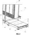
- FIG. 4 is an enlarged three-dimensional representation of the loading platform engaged to the MDC of FIG. 3 , according to one or more embodiments;
- FIG. 5 is an enlarged three-dimensional representation of a transition plate positioned between a proximal edge of the loading platform and the MDC of FIG. 3 , according to one or more embodiments;
- FIG. 6 is an enlarged three-dimensional representation of a docking alignment plate attached to a raised floor of the MDC of FIG. 3 , according to one or more embodiments;
- FIG. 7 is an enlarged three-dimensional representation of the rack shock pallet engaged to the pallet interface on a distal edge of the loading platform of FIG. 3 , according to one or more embodiments;
- FIG. 8 is an enlarged three-dimensional representation of an underside of the rack shock pallet engaged to the pallet interface, according to one or more embodiments
- FIG. 9 is a three-dimensional representation of the MDC of FIG. 3 with a pallet jack of an RIHS delivery kit on the loading platform, according to one or more embodiments;
- FIG. 10 is a three-dimensional representation of the MDC of FIG. 3 with the pallet jack engaged to the RIHS, according to one or more embodiments;
- FIG. 11 is a perspective view of a first RIHS moved to a loading platform attached to a MDC, according to one or more embodiments;
- FIG. 12 is a perspective view of rack shock pallet engaged to the loading platform, according to one or more embodiments.
- FIGS. 13 A and 13 B ( FIG. 13 ) is a flow chart of a method for removing an RIHS from and delivering an RIHS to a data center, according to one or more embodiments.
- the illustrative embodiments provide a data center, a rack information handling system (RIHS) delivery kit, and a method for removing an RIHS from and delivering an RIHS to a data center.
- the RIHS delivery kit mitigates differences in surface level between a transport vehicle and the data center. Loading and unloading of roll-off rack shock pallets onto a surface that is horizontally aligned ensures stable positioning of the RIHS during transfer.
- a data center includes an enclosure having a raised floor and a lateral opening.
- the lateral opening has a bottom edge that is aligned with the raised floor in order to transfer a RIHS through the lateral opening for a selected one of: (i) removing the RIHSs from the raised floor; and (ii) delivering the RIHS to the raised floor.
- the data center includes a pallet interface coupled to or integrated into an exterior edge of the data center aligned with the raised floor and vertically presented to abut and engage a lateral edge of a roll-off rack shock pallet that supports the RIHS during transport.
- the pallet interface facilitates correctly aligning a rack shock pallet level with the edge of the raised floor of the data center so that the RIHS can be readily moved onto or off of the pallet, especially if the rack shock pallet is configured for roll-off of the RIHS.
- a forklift which moves the rack shock pallet to the data center, causes the rack shock pallet to engage the pallet interface aligning the pallet without having to place the pallet itself on a dock or the raised floor. The forklift supports the engaged rack shock pallet during either unloading of the RIHS from the pallet or loading the RIHS onto the pallet.
- an RIHS delivery kit is temporarily used at the data center to deliver or remove RIHSs through a particular lateral opening.
- an RIHS delivery kit includes a docking alignment plate and a loading dock/platform that has the pallet interface.
- the loading platform interposes between the raised floor of the data center and the pallet interface of the loading dock.
- the loading platform provides workspace for intermediate placement of the RIHS when transitioning from pallet to pallet jack.
- the pallet interface facilitates engagement of the rack shock pallet, and the docking alignment plate facilitates engagement of the loading platform to the data center.
- the docking alignment plate is attachable to a raised floor of an enclosure of a data center.
- the enclosure has a raised floor and a lateral opening having a bottom edge that is aligned with the raised floor in order to transfer an RIHS through the lateral opening for a selected one of: (i) removing the RIHS from the raised floor; and (ii) delivering the RIHS to the raised floor.
- the docking alignment plate is horizontally alignable with the lateral opening of the enclosure.
- the RIHS delivery kit includes a loading platform having a first edge engagement to the docking alignment plate to align an upper surface of the loading platform with the raised floor of the enclosure.
- the loading platform has a second edge that comprises a pallet interface that is vertically presented to abut and engage a lateral edge of a roll-off rack shock pallet that supports the RIHS during transport.
- a method for removing an RIHS from and delivering an RIHS to a data center.
- the method includes horizontally aligning a docking alignment plate with a lateral opening to an enclosure of the data center having a raised floor.
- the lateral opening has a bottom edge that is aligned with the raised floor in order to transfer an RIHS through the lateral opening for a selected one of: (i) removing the RIHS from the raised floor; and (ii) delivering the RIHS to the raised floor.
- the method includes attaching the docking alignment plate to an exterior edge of the raised floor beneath the lateral opening.
- the method includes engaging a first edge of a loading platform to the docking alignment plate that aligns an upper surface of the loading platform to the raised floor.
- the method includes engaging a lateral edge of a roll-off rack shock pallet to an exterior facing second edge of the loading platform.
- the method includes translating an RIHS between the roll-off rack shock pallet and the loading platform.
- the floor of the data center is raised at least to a height of a rack shock pallet and is not level with the surrounding surface.
- the floor of the data center can be raised to any height that can be accommodated by a forklift vehicle.
- references within the specification to “one embodiment,” “an embodiment,” “embodiments”, or “one or more embodiments” are intended to indicate that a particular feature, structure, or characteristic described in connection with the embodiment is included in at least one embodiment of the present disclosure.
- the appearance of such phrases in various places within the specification are not necessarily all referring to the same embodiment, nor are separate or alternative embodiments mutually exclusive of other embodiments.
- various features are described which may be exhibited by some embodiments and not by others.
- various requirements are described which may be requirements for some embodiments but not other embodiments.
- FIG. 1 depicts a three-dimensional representation of example data center 100 , within which one or more of the described features of the various embodiments of the disclosure can be implemented.
- Data center 100 includes enclosure 102 having raised floor 104 and lateral opening 106 having bottom edge 108 that is horizontally aligned with the raised floor 104 .
- enclosure 102 is a building that is assembled at a fixed location.
- enclosure 102 is a volumetric container of a modular data center (MDC).
- Pallet interface 110 is coupled to raised floor 104 and vertically presented below lateral opening 106 . As depicted in FIG. 2 , pallet interface 110 is intended to abut and engage lateral edge 112 of rack shock pallet 114 .
- alignment of rack shock pallet 114 with raised floor 104 means linear alignment and close proximity of abutting edges of rack shock pallet 114 with raised floor 104 .
- alignment of rack shock pallet 114 with raised floor 104 additionally means that a geometric plane of raised floor 104 is in alignment with a geometric plane of top surface of rack shock pallet 114 .
- the geometric planes of rack shock pallet 114 with raised floor 104 are both horizontal and at the same vertical height for alignment.
- pallet shock pallet 114 supports rack information handling system (RIHS) 116 during transport.
- Pallet interface 110 enables transfer of RIHS 116 through lateral opening 106 for a selected one of: (i) removing RIHS 116 from raised floor 104 and (ii) delivering RIHS 116 to raised floor 104 .
- an information handling system such as RIHS 116 , may include any instrumentality or aggregate of instrumentalities operable to compute, classify, process, transmit, receive, retrieve, originate, switch, store, display, manifest, detect, record, reproduce, handle, or utilize any form of information, intelligence, or data for business, scientific, control, or other purposes.
- an information handling system may be a handheld device, personal computer, a server, a network storage device, or any other suitable device and may vary in size, shape, performance, functionality, and price.
- the information handling system may include random access memory (RAM), one or more processing resources such as a central processing unit (CPU) or hardware or software control logic, ROM, and/or other types of nonvolatile memory.
- Additional components of the information handling system may include one or more disk drives, one or more network ports for communicating with external devices as well as various input and output (I/O) devices, such as a keyboard, a mouse, and a video display.
- the information handling system may also include one or more buses operable to transmit communications between the various hardware components.
- pallet interface 110 includes top guide(s) 118 extending from top edge 120 of mounting plate 122 of pallet interface 110 .
- Top guide(s) 118 are positioned to contact top surface 124 of rack shock pallet 114 .
- Bottom guide(s) 126 extend from bottom edge 128 of mounting plate 122 to provide surface-to-surface contact with downward surface 130 of rack shock pallet 114 .
- pallet interface 110 has fastener holes 133 through which fasteners 135 are engaged to data center 100 .
- pallet interface 110 ( FIG. 1 ) comprises metal that is welded to a metal frame of data center 100 .
- FIG. 2 depicts a three-dimensional representation of example data center 100 having pallet interface 110 engaged to rack shock pallet 114 .
- Top guide(s) 118 and bottom guide(s) 126 receive and align rack shock pallet 114 .
- RIHS 116 is rolled through lateral opening 106 into enclosure 102 of data center 100 using castors 132 .
- RIHS 116 is slid or lifted off of rack shock pallet 114 by a pallet jack that is used on raised floor 104 .
- FIG. 3 depicts a three-dimensional representation of example modular data center (MDC) 300 having, as an enclosure, elongated volumetric container 302 , such as an information technology (IT) pre-assembled component (ITPAC) container that is transportable as a modular data center (MDC).
- MDC modular data center
- Raised floor 104 is shaped to receive a first in, first out (FIFO) longitudinal row of RIHSs 116 through lateral opening 106 .
- Pallet interface 110 is attached to loading platform 305 , which is temporarily mounted to raised floor 104 .
- Loading platform 305 provides a loading surface 307 that is aligned with raised floor 104 .
- alignment of with raised floor 104 means linear alignment and close proximity of abutting edges of loading surface 307 with raised floor 104 of MDC 300 .
- Placement of pallet interface 110 provides the linear alignment.
- Loading surface 307 of loading platform 305 can provide a work area, such as for engaging a pallet jack 309 .
- pallet interface 110 is attached to distal, outward edge 311 of loading platform 305 .
- FIG. 4 is an enlarged, three-dimensional representation of loading platform 305 engaged to raised floor 104 of volumetric container 302 .
- Transition plate 413 is inserted in lateral opening 106 between raised floor 104 and loading platform 305 to provide a smooth rolling surface.
- Height adjustable supports 415 are extendable downward from loading platform 305 to rest on ground surface 417 in order to level loading surface 307 of loading platform 305 relative to raised floor 104 .
- alignment of loading surface 307 and rack shock pallet 114 with raised floor 104 additionally means that a geometric plane of raised floor 104 is in alignment with a geometric plane of loading surface 307 .
- the geometric planes of loading surface 307 with raised floor 104 are both horizontal and at the same vertical height for alignment.
- FIG. 5 is an enlarged three-dimensional representation of transition plate 413 positioned between a proximal edge of loading platform 305 and MDC 300 .
- Transition plate 413 covers a gap between raised floor 104 and loading platform 305 that would interfere with a pallet jack.
- Fastener holes 514 aligns fasteners to both MDC 300 and loading platform 305 , securing loading platform 305 .
- FIG. 6 is an enlarged three-dimensional representation of docking alignment plate 617 attached to an exterior edge of volumetric container 302 . Extending horizontally from docking alignment plate 617 are lower outboard male engagement members 619 a, b and upper inboard male engagement members 621 a, b .
- FIG. 7 there is illustrated an enlarged three-dimensional representation of an underside of loading platform 305 .
- Loading platform 305 incudes lower outboard female engagement members 723 a, b and upper inboard female engagement member 725 a, b that respectively engage in a complementary way to lower outboard male engagement members 619 a, b and upper inboard male engagement member 621 a, b of docking alignment plate 617 .
- alignment of rack shock pallet 114 , with loading platform 305 means linear alignment and close proximity of abutting edges of rack shock pallet 114 with loading platform 305 . This linear alignment is provided by placement of pallet interface 110 on loading platform 305 .
- alignment of rack shock pallet 114 with loading platform 305 additionally means that a geometric plane of loading platform 305 is in alignment with a geometric plane of top surface 124 of rack shock pallet 114 .
- the geometric planes of rack shock pallet 114 with loading platform 305 are both horizontal and at the same vertical height for alignment.
- FIG. 9 is a three-dimensional representation of MDC 300 with pallet jack 927 that is sized to pass through lateral opening 106 .
- RIHS delivery kit 929 includes pallet jack 927 that is selected or customized for moving on loading platform 305 and through lateral opening 106 .
- RIHS delivery kit 929 also includes loading platform 305 , pallet interface 110 , and docking alignment plate 617 ( FIG. 6 ).
- MDC 300 is prepared for transfer of RIHSs by attaching components of RIHS delivery kit 929 , which can be reused at other locations, reducing the cost of the MDC 300 .
- removal of loading platform 305 reduces the footprint of MDC 300 .
- Pallet jack 927 is no wider than lateral opening 106 . In one or more embodiments, pallet jack 927 is no wider than lateral opening RIHS 116 and is able to maneuver on the width provided by loading platform 305 .
- FIG. 11 is a perspective view of RIHS 116 moved from enclosure 302 onto loading platform 305 .
- Pallet jack 927 is placed aside on loading platform 305 .
- Forklift 1231 is provided for used with RIHS delivery kit 929 to facilitate transfer of RIHSs 116 from MDC 300 .
- FIG. 12 there is illustrated a perspective view of rack shock pallet 114 engaged to loading platform 305 .
- Forklift 1231 supports and positions rack shock pallet 114 in preparation for receiving the weight of RIHS 116 .
- Forklift 1231 then moves RIHS 116 to truck 1233 for taking away.
- New RIHSs 1214 that were delivered by truck 1233 are moved into MDC 300 using a reverse procedure.
- FIGS. 13 A- 13 B present a flow chart of method 1300 for removing RIHS 116 from and delivering an RIHS 116 to data center 100 ( FIG. 1 ).
- the description of method 1300 is provided with general reference to the specific components illustrated within the preceding FIGS. 1 - 12 .
- method 1300 can be implemented using automated assembly equipment or machines that are at least partially controlled by a controller or IHS.
- method 1300 includes horizontally aligning a docking alignment plate with a lateral opening of a data center enclosure having a raised floor.
- the lateral opening has a bottom edge that is aligned with the raised floor in order to transfer an RIHS through the lateral opening for a selected one of: (i) removing the RIHSs from the raised floor; and (ii) delivering the RIHS to the raised floor (block 1302 ).
- Method 1300 includes attaching the docking alignment plate to an exterior edge of the enclosure, beneath the lateral opening (block 1304 ).
- Method 1300 includes engaging male engagement features of the docking alignment plate to female engagement features of the first edge of the loading platform, or vice versa (block 1306 ). That is, in an alternate embodiment, method 1300 includes engaging female engagement features of docking alignment plate to make engagement features or the edge of the loading platform.
- Method 1300 includes adjusting two or more height adjustable supports extendable downward from the loading platform in order to horizontally level the loading platform (block 1308 ).
- Method 1300 includes positioning a transition plate in the opening between the raised floor and an upper surface of the loading platform to provide a level sliding surface (block 1310 ).
- method 1300 includes supporting the roll-off rack shock pallet with a forklift engaged to the roll-off rack shock pallet on a side of the roll-off rack shock pallet opposite to the loading platform (block 1312 ).
- Method 1300 includes horizontally moving the roll-off rack shock pallet between at least one top guide and at least one bottom guide of the pallet interface (block 1314 ).
- the at least one top guide extends from a top edge of the pallet interface to contact a top surface of the roll-off rack shock pallet.
- the at least one bottom guide contacts a downward surface of the roll-off rack shock pallet.
- Method 1300 includes abutting a lateral edge of a roll-off rack shock pallet to the pallet interface attached to a second edge of the loading platform to complete the engagement to the at least one top guide and the at least one bottom guide (block 1316 ).
- Method 1300 includes translating an RIHS between the roll-off rack shock pallet and the loading platform (block 1318 ).
- Method 1300 includes transferring the RIHS through the lateral opening using a pallet jack sized for the lateral opening (block 1320 ). Then method 1300 ends.
- one or more of the methods may be embodied in a computer readable medium containing computer readable code such that a series of functional processes are performed when the computer readable code is executed on a computing device.
- certain steps of the methods are combined, performed simultaneously or in a different order, or perhaps omitted, without deviating from the scope of the disclosure.
- the method blocks are described and illustrated in a particular sequence, use of a specific sequence of functional processes represented by the blocks is not meant to imply any limitations on the disclosure. Changes may be made with regards to the sequence of processes without departing from the scope of the present disclosure. Use of a particular sequence is therefore, not to be taken in a limiting sense, and the scope of the present disclosure is defined only by the appended claims.
- These computer program instructions may be provided to a processor of a general purpose computer, special purpose computer, such as a service processor, or other programmable data processing apparatus to produce a machine, such that the instructions, which execute via the processor of the computer or other programmable data processing apparatus, performs the method for implementing the functions/acts specified in the flowchart and/or block diagram block or blocks.
- One or more of the embodiments of the disclosure described can be implementable, at least in part, using a software-controlled programmable processing device, such as a microprocessor, digital signal processor or other processing device, data processing apparatus or system.
- a computer program for configuring a programmable device, apparatus or system to implement the foregoing described methods is envisaged as an aspect of the present disclosure.
- the computer program may be embodied as source code or undergo compilation for implementation on a processing device, apparatus, or system.
- the computer program is stored on a carrier device in machine or device readable form, for example in solid-state memory, magnetic memory such as disk or tape, optically or magneto-optically readable memory such as compact disk or digital versatile disk, flash memory, etc.
- the processing device, apparatus or system utilizes the program or a part thereof to configure the processing device, apparatus, or system for operation.
- aspects of the present disclosure may be implemented using any combination of software, firmware or hardware. Accordingly, aspects of the present disclosure may take the form of an entirely hardware embodiment or an embodiment combining software (including firmware, resident software, micro-code, etc.) and hardware aspects that may all generally be referred to herein as a “circuit,” “module,” or “system.” Furthermore, aspects of the present disclosure may take the form of a computer program product embodied in one or more computer readable storage device(s) having computer readable program code embodied thereon. Any combination of one or more computer readable storage device(s) may be utilized.
- the computer readable storage device may be, for example, but not limited to, an electronic, magnetic, optical, electromagnetic, infrared, or semiconductor system, apparatus, or device, or any suitable combination of the foregoing. More specific examples (a non-exhaustive list) of the computer readable storage device would include the following: an electrical connection having one or more wires, a portable computer diskette, a hard disk, a random access memory (RAM), a read-only memory (ROM), an erasable programmable read-only memory (EPROM or Flash memory), an optical fiber, a portable compact disc read-only memory (CD-ROM), an optical storage device, a magnetic storage device, or any suitable combination of the foregoing.
- a computer readable storage device may be any tangible medium that can contain, or store a program for use by or in connection with an instruction execution system, apparatus, or device.
Abstract
Description
Claims (20)
Priority Applications (1)
| Application Number | Priority Date | Filing Date | Title |
|---|---|---|---|
| US16/685,964 US11533821B2 (en) | 2019-11-15 | 2019-11-15 | Pallet interface for data center and rack information handling systems |
Applications Claiming Priority (1)
| Application Number | Priority Date | Filing Date | Title |
|---|---|---|---|
| US16/685,964 US11533821B2 (en) | 2019-11-15 | 2019-11-15 | Pallet interface for data center and rack information handling systems |
Publications (2)
| Publication Number | Publication Date |
|---|---|
| US20210153375A1 US20210153375A1 (en) | 2021-05-20 |
| US11533821B2 true US11533821B2 (en) | 2022-12-20 |
Family
ID=75909119
Family Applications (1)
| Application Number | Title | Priority Date | Filing Date |
|---|---|---|---|
| US16/685,964 Active 2041-03-19 US11533821B2 (en) | 2019-11-15 | 2019-11-15 | Pallet interface for data center and rack information handling systems |
Country Status (1)
| Country | Link |
|---|---|
| US (1) | US11533821B2 (en) |
Families Citing this family (1)
| Publication number | Priority date | Publication date | Assignee | Title |
|---|---|---|---|---|
| US11943891B2 (en) * | 2020-05-08 | 2024-03-26 | Gulfstream Aerospace Corporation | Method and apparatus for electronics rack assembly and transportation |
Citations (23)
| Publication number | Priority date | Publication date | Assignee | Title |
|---|---|---|---|---|
| US20080056867A1 (en) | 2006-09-06 | 2008-03-06 | Zuckerman Raymond S | Computer server lift with slideable horizontal surface |
| US20100176076A1 (en) * | 2009-01-15 | 2010-07-15 | Kern Karl C | Decking beam rack apparatus and method |
| US20130321132A1 (en) * | 2012-05-29 | 2013-12-05 | Hon Hai Precision Industry Co., Ltd. | Management system for container data center |
| US20130345887A1 (en) * | 2012-06-20 | 2013-12-26 | Microsoft Corporation | Infrastructure based computer cluster management |
| US20150058542A1 (en) * | 2013-08-23 | 2015-02-26 | International Business Machines Corporation | Updating techniques for memory of a chassis management module |
| US20150181750A1 (en) * | 2013-12-23 | 2015-06-25 | Dell, Inc. | Modularly-expandable mini-rack server system |
| US20160039568A1 (en) * | 2014-08-06 | 2016-02-11 | Telair International Gmbh | Pallet Adapter Kit and Loading Unit With Corresponding Pallet Adapter Kit |
| US9574883B2 (en) * | 2015-03-24 | 2017-02-21 | X Development Llc | Associating semantic location data with automated environment mapping |
| US9701330B2 (en) | 2014-10-31 | 2017-07-11 | Hewlett Packard Enterprise Development Lp | Server rack lift |
| US9795062B1 (en) * | 2016-06-29 | 2017-10-17 | Amazon Technologies, Inc. | Portable data center for data transfer |
| US9843470B1 (en) * | 2013-09-27 | 2017-12-12 | Amazon Technologies, Inc. | Portable data center |
| US10093450B2 (en) | 2016-11-07 | 2018-10-09 | Dell Products, L.P. | Transportation pallet and method for depalletizing load |
| US10118777B1 (en) | 2017-04-28 | 2018-11-06 | Hewlett Packard Enterprise Development Lp | Server rack ramps with linkage-arm hinges |
| US10398061B1 (en) * | 2016-06-29 | 2019-08-27 | Amazon Technologies, Inc. | Portable data center for data transfer |
| US10398055B1 (en) * | 2018-06-27 | 2019-08-27 | Amazon Technologies, Inc. | Portable server assembly system |
| US10440863B1 (en) * | 2018-04-25 | 2019-10-08 | Dell Products, L.P. | System and method to enable large-scale data computation during transportation |
| US20190332822A1 (en) * | 2018-04-25 | 2019-10-31 | Dell Products, L.P. | High capacity, secure access, mobile storage exchange system |
| US10853248B1 (en) * | 2018-02-05 | 2020-12-01 | Amazon Technologies, Inc. | In-rack network for power signals |
| US20210092875A1 (en) * | 2017-10-31 | 2021-03-25 | Envion Ag | Mobile data center and method of operating the same |
| US20210112677A1 (en) * | 2019-10-15 | 2021-04-15 | Dell Products, L.P. | Modular data center power distribution system |
| US20210127523A1 (en) * | 2019-10-23 | 2021-04-29 | Dell Products, L.P. | Isolating information handling system racks from shock and vibration in a modular data center |
| US20210360817A1 (en) * | 2018-12-12 | 2021-11-18 | New H3C Technologies Co., Ltd. | Intelligent Lug |
| US11191181B1 (en) * | 2018-06-27 | 2021-11-30 | Amazon Technologies, Inc. | Custom server assembly |
-
2019
- 2019-11-15 US US16/685,964 patent/US11533821B2/en active Active
Patent Citations (23)
| Publication number | Priority date | Publication date | Assignee | Title |
|---|---|---|---|---|
| US20080056867A1 (en) | 2006-09-06 | 2008-03-06 | Zuckerman Raymond S | Computer server lift with slideable horizontal surface |
| US20100176076A1 (en) * | 2009-01-15 | 2010-07-15 | Kern Karl C | Decking beam rack apparatus and method |
| US20130321132A1 (en) * | 2012-05-29 | 2013-12-05 | Hon Hai Precision Industry Co., Ltd. | Management system for container data center |
| US20130345887A1 (en) * | 2012-06-20 | 2013-12-26 | Microsoft Corporation | Infrastructure based computer cluster management |
| US20150058542A1 (en) * | 2013-08-23 | 2015-02-26 | International Business Machines Corporation | Updating techniques for memory of a chassis management module |
| US9843470B1 (en) * | 2013-09-27 | 2017-12-12 | Amazon Technologies, Inc. | Portable data center |
| US20150181750A1 (en) * | 2013-12-23 | 2015-06-25 | Dell, Inc. | Modularly-expandable mini-rack server system |
| US20160039568A1 (en) * | 2014-08-06 | 2016-02-11 | Telair International Gmbh | Pallet Adapter Kit and Loading Unit With Corresponding Pallet Adapter Kit |
| US9701330B2 (en) | 2014-10-31 | 2017-07-11 | Hewlett Packard Enterprise Development Lp | Server rack lift |
| US9574883B2 (en) * | 2015-03-24 | 2017-02-21 | X Development Llc | Associating semantic location data with automated environment mapping |
| US9795062B1 (en) * | 2016-06-29 | 2017-10-17 | Amazon Technologies, Inc. | Portable data center for data transfer |
| US10398061B1 (en) * | 2016-06-29 | 2019-08-27 | Amazon Technologies, Inc. | Portable data center for data transfer |
| US10093450B2 (en) | 2016-11-07 | 2018-10-09 | Dell Products, L.P. | Transportation pallet and method for depalletizing load |
| US10118777B1 (en) | 2017-04-28 | 2018-11-06 | Hewlett Packard Enterprise Development Lp | Server rack ramps with linkage-arm hinges |
| US20210092875A1 (en) * | 2017-10-31 | 2021-03-25 | Envion Ag | Mobile data center and method of operating the same |
| US10853248B1 (en) * | 2018-02-05 | 2020-12-01 | Amazon Technologies, Inc. | In-rack network for power signals |
| US10440863B1 (en) * | 2018-04-25 | 2019-10-08 | Dell Products, L.P. | System and method to enable large-scale data computation during transportation |
| US20190332822A1 (en) * | 2018-04-25 | 2019-10-31 | Dell Products, L.P. | High capacity, secure access, mobile storage exchange system |
| US10398055B1 (en) * | 2018-06-27 | 2019-08-27 | Amazon Technologies, Inc. | Portable server assembly system |
| US11191181B1 (en) * | 2018-06-27 | 2021-11-30 | Amazon Technologies, Inc. | Custom server assembly |
| US20210360817A1 (en) * | 2018-12-12 | 2021-11-18 | New H3C Technologies Co., Ltd. | Intelligent Lug |
| US20210112677A1 (en) * | 2019-10-15 | 2021-04-15 | Dell Products, L.P. | Modular data center power distribution system |
| US20210127523A1 (en) * | 2019-10-23 | 2021-04-29 | Dell Products, L.P. | Isolating information handling system racks from shock and vibration in a modular data center |
Also Published As
| Publication number | Publication date |
|---|---|
| US20210153375A1 (en) | 2021-05-20 |
Similar Documents
| Publication | Publication Date | Title |
|---|---|---|
| US9758277B2 (en) | Shock pallet with adjustable anti-tip mechanism | |
| US20220332505A1 (en) | Delivery apparatus, system, method, electronic device and computer readable storage medium | |
| ATE478021T1 (en) | MATERIAL HANDLING SYSTEM AND METHOD USING INDEPENDENT MOBILE DRIVE UNITS AND MOVABLE STORAGE CONTAINERS | |
| US11533821B2 (en) | Pallet interface for data center and rack information handling systems | |
| AU2020368945A1 (en) | Merging processing system, method and device | |
| US20230174305A1 (en) | Three-dimensional warehouse handling and dispatching system and method for implementing item picking | |
| WO2022206791A1 (en) | Picking system and method | |
| CN113213340B (en) | Method, system, equipment and storage medium for unloading collection card based on lockhole identification | |
| CN112801582A (en) | Unmanned archive storehouse system | |
| WO2022222801A1 (en) | Warehousing management method and apparatus, warehousing robot, warehousing system, and medium | |
| MX2022005713A (en) | External robotic system for liquid immersion cooling platform. | |
| CN108146956A (en) | Full-automatic warehouse system based on robot technology | |
| CN208796292U (en) | A kind of material Management System | |
| CN207917737U (en) | Robot | |
| US20160016769A1 (en) | Integrated rack lifting apparatus | |
| CN113003086B (en) | Cargo carrying method, cargo carrying equipment and storage medium | |
| CN109720770B (en) | Handling method and device for processed goods, computer equipment and storage medium | |
| CN112001053B (en) | Goods shelf data processing method, device, electronic equipment and readable medium | |
| CN207684282U (en) | Full-automatic warehouse system based on robot technology | |
| CN208021946U (en) | A kind of transport device of SMT charging trays | |
| TW552542B (en) | Control method of carrier transportation and system thereof | |
| WO2022155236A3 (en) | Transport rack and transport rack docking interface | |
| CN212607299U (en) | Connection support and storage logistics system | |
| US20230418294A1 (en) | Intrusive industrial vehicle alignment | |
| CN217375884U (en) | Intelligent material storing and taking equipment |
Legal Events
| Date | Code | Title | Description |
|---|---|---|---|
| AS | Assignment |
Owner name: DELL PRODUCTS, L.P., TEXAS Free format text: ASSIGNMENT OF ASSIGNORS INTEREST;ASSIGNORS:BAILEY, MARK M.;MIDDLETON, ANTHONY P.;SAYLES, JEFFERY T.;REEL/FRAME:051025/0833 Effective date: 20191114 |
|
| FEPP | Fee payment procedure |
Free format text: ENTITY STATUS SET TO UNDISCOUNTED (ORIGINAL EVENT CODE: BIG.); ENTITY STATUS OF PATENT OWNER: LARGE ENTITY |
|
| AS | Assignment |
Owner name: THE BANK OF NEW YORK MELLON TRUST COMPANY, N.A., AS COLLATERAL AGENT, TEXAS Free format text: PATENT SECURITY AGREEMENT (NOTES);ASSIGNORS:DELL PRODUCTS L.P.;EMC IP HOLDING COMPANY LLC;REEL/FRAME:052216/0758 Effective date: 20200324 |
|
| AS | Assignment |
Owner name: CREDIT SUISSE AG, CAYMAN ISLANDS BRANCH, NORTH CAROLINA Free format text: SECURITY AGREEMENT;ASSIGNORS:DELL PRODUCTS L.P.;EMC IP HOLDING COMPANY LLC;REEL/FRAME:052243/0773 Effective date: 20200326 |
|
| AS | Assignment |
Owner name: THE BANK OF NEW YORK MELLON TRUST COMPANY, N.A., TEXAS Free format text: SECURITY AGREEMENT;ASSIGNORS:CREDANT TECHNOLOGIES INC.;DELL INTERNATIONAL L.L.C.;DELL MARKETING L.P.;AND OTHERS;REEL/FRAME:053546/0001 Effective date: 20200409 |
|
| AS | Assignment |
Owner name: THE BANK OF NEW YORK MELLON TRUST COMPANY, N.A., AS COLLATERAL AGENT, TEXAS Free format text: SECURITY INTEREST;ASSIGNORS:DELL PRODUCTS L.P.;EMC CORPORATION;EMC IP HOLDING COMPANY LLC;REEL/FRAME:053311/0169 Effective date: 20200603 |
|
| STPP | Information on status: patent application and granting procedure in general |
Free format text: DOCKETED NEW CASE - READY FOR EXAMINATION |
|
| AS | Assignment |
Owner name: EMC IP HOLDING COMPANY LLC, TEXAS Free format text: RELEASE OF SECURITY INTEREST AF REEL 052243 FRAME 0773;ASSIGNOR:CREDIT SUISSE AG, CAYMAN ISLANDS BRANCH;REEL/FRAME:058001/0152 Effective date: 20211101 Owner name: DELL PRODUCTS L.P., TEXAS Free format text: RELEASE OF SECURITY INTEREST AF REEL 052243 FRAME 0773;ASSIGNOR:CREDIT SUISSE AG, CAYMAN ISLANDS BRANCH;REEL/FRAME:058001/0152 Effective date: 20211101 |
|
| STPP | Information on status: patent application and granting procedure in general |
Free format text: NON FINAL ACTION MAILED |
|
| AS | Assignment |
Owner name: EMC IP HOLDING COMPANY LLC, TEXAS Free format text: RELEASE OF SECURITY INTEREST IN PATENTS PREVIOUSLY RECORDED AT REEL/FRAME (053311/0169);ASSIGNOR:THE BANK OF NEW YORK MELLON TRUST COMPANY, N.A., AS NOTES COLLATERAL AGENT;REEL/FRAME:060438/0742 Effective date: 20220329 Owner name: EMC CORPORATION, MASSACHUSETTS Free format text: RELEASE OF SECURITY INTEREST IN PATENTS PREVIOUSLY RECORDED AT REEL/FRAME (053311/0169);ASSIGNOR:THE BANK OF NEW YORK MELLON TRUST COMPANY, N.A., AS NOTES COLLATERAL AGENT;REEL/FRAME:060438/0742 Effective date: 20220329 Owner name: DELL PRODUCTS L.P., TEXAS Free format text: RELEASE OF SECURITY INTEREST IN PATENTS PREVIOUSLY RECORDED AT REEL/FRAME (053311/0169);ASSIGNOR:THE BANK OF NEW YORK MELLON TRUST COMPANY, N.A., AS NOTES COLLATERAL AGENT;REEL/FRAME:060438/0742 Effective date: 20220329 Owner name: EMC IP HOLDING COMPANY LLC, TEXAS Free format text: RELEASE OF SECURITY INTEREST IN PATENTS PREVIOUSLY RECORDED AT REEL/FRAME (052216/0758);ASSIGNOR:THE BANK OF NEW YORK MELLON TRUST COMPANY, N.A., AS NOTES COLLATERAL AGENT;REEL/FRAME:060438/0680 Effective date: 20220329 Owner name: DELL PRODUCTS L.P., TEXAS Free format text: RELEASE OF SECURITY INTEREST IN PATENTS PREVIOUSLY RECORDED AT REEL/FRAME (052216/0758);ASSIGNOR:THE BANK OF NEW YORK MELLON TRUST COMPANY, N.A., AS NOTES COLLATERAL AGENT;REEL/FRAME:060438/0680 Effective date: 20220329 |
|
| STPP | Information on status: patent application and granting procedure in general |
Free format text: RESPONSE TO NON-FINAL OFFICE ACTION ENTERED AND FORWARDED TO EXAMINER |
|
| STPP | Information on status: patent application and granting procedure in general |
Free format text: NOTICE OF ALLOWANCE MAILED -- APPLICATION RECEIVED IN OFFICE OF PUBLICATIONS |
|
| STPP | Information on status: patent application and granting procedure in general |
Free format text: PUBLICATIONS -- ISSUE FEE PAYMENT VERIFIED |
|
| STCF | Information on status: patent grant |
Free format text: PATENTED CASE |