US11519174B2 - Building structure formed by truss modules and method of forming - Google Patents
Building structure formed by truss modules and method of forming Download PDFInfo
- Publication number
- US11519174B2 US11519174B2 US16/906,435 US202016906435A US11519174B2 US 11519174 B2 US11519174 B2 US 11519174B2 US 202016906435 A US202016906435 A US 202016906435A US 11519174 B2 US11519174 B2 US 11519174B2
- Authority
- US
- United States
- Prior art keywords
- structural truss
- chords
- elongated
- modules
- pair
- Prior art date
- Legal status (The legal status is an assumption and is not a legal conclusion. Google has not performed a legal analysis and makes no representation as to the accuracy of the status listed.)
- Active, expires
Links
Images


Classifications
-
- E—FIXED CONSTRUCTIONS
- E04—BUILDING
- E04C—STRUCTURAL ELEMENTS; BUILDING MATERIALS
- E04C3/00—Structural elongated elements designed for load-supporting
- E04C3/02—Joists; Girders, trusses, or trusslike structures, e.g. prefabricated; Lintels; Transoms; Braces
- E04C3/12—Joists; Girders, trusses, or trusslike structures, e.g. prefabricated; Lintels; Transoms; Braces of wood, e.g. with reinforcements, with tensioning members
- E04C3/16—Joists; Girders, trusses, or trusslike structures, e.g. prefabricated; Lintels; Transoms; Braces of wood, e.g. with reinforcements, with tensioning members with apertured web, e.g. trusses
-
- E—FIXED CONSTRUCTIONS
- E04—BUILDING
- E04B—GENERAL BUILDING CONSTRUCTIONS; WALLS, e.g. PARTITIONS; ROOFS; FLOORS; CEILINGS; INSULATION OR OTHER PROTECTION OF BUILDINGS
- E04B1/00—Constructions in general; Structures which are not restricted either to walls, e.g. partitions, or floors or ceilings or roofs
- E04B1/003—Balconies; Decks
-
- E—FIXED CONSTRUCTIONS
- E04—BUILDING
- E04B—GENERAL BUILDING CONSTRUCTIONS; WALLS, e.g. PARTITIONS; ROOFS; FLOORS; CEILINGS; INSULATION OR OTHER PROTECTION OF BUILDINGS
- E04B2/00—Walls, e.g. partitions, for buildings; Wall construction with regard to insulation; Connections specially adapted to walls
- E04B2/56—Load-bearing walls of framework or pillarwork; Walls incorporating load-bearing elongated members
- E04B2/70—Load-bearing walls of framework or pillarwork; Walls incorporating load-bearing elongated members with elongated members of wood
- E04B2/706—Load-bearing walls of framework or pillarwork; Walls incorporating load-bearing elongated members with elongated members of wood with supporting function
- E04B2/707—Load-bearing walls of framework or pillarwork; Walls incorporating load-bearing elongated members with elongated members of wood with supporting function obturation by means of panels
-
- E—FIXED CONSTRUCTIONS
- E04—BUILDING
- E04B—GENERAL BUILDING CONSTRUCTIONS; WALLS, e.g. PARTITIONS; ROOFS; FLOORS; CEILINGS; INSULATION OR OTHER PROTECTION OF BUILDINGS
- E04B5/00—Floors; Floor construction with regard to insulation; Connections specially adapted therefor
- E04B5/02—Load-carrying floor structures formed substantially of prefabricated units
- E04B5/12—Load-carrying floor structures formed substantially of prefabricated units with wooden beams
-
- E—FIXED CONSTRUCTIONS
- E04—BUILDING
- E04C—STRUCTURAL ELEMENTS; BUILDING MATERIALS
- E04C3/00—Structural elongated elements designed for load-supporting
- E04C3/02—Joists; Girders, trusses, or trusslike structures, e.g. prefabricated; Lintels; Transoms; Braces
- E04C3/29—Joists; Girders, trusses, or trusslike structures, e.g. prefabricated; Lintels; Transoms; Braces built-up from parts of different material, i.e. composite structures
- E04C3/292—Joists; Girders, trusses, or trusslike structures, e.g. prefabricated; Lintels; Transoms; Braces built-up from parts of different material, i.e. composite structures the materials being wood and metal
-
- E—FIXED CONSTRUCTIONS
- E04—BUILDING
- E04B—GENERAL BUILDING CONSTRUCTIONS; WALLS, e.g. PARTITIONS; ROOFS; FLOORS; CEILINGS; INSULATION OR OTHER PROTECTION OF BUILDINGS
- E04B1/00—Constructions in general; Structures which are not restricted either to walls, e.g. partitions, or floors or ceilings or roofs
- E04B1/18—Structures comprising elongated load-supporting parts, e.g. columns, girders, skeletons
- E04B1/26—Structures comprising elongated load-supporting parts, e.g. columns, girders, skeletons the supporting parts consisting of wood
- E04B2001/2696—Shear bracing
-
- E—FIXED CONSTRUCTIONS
- E04—BUILDING
- E04C—STRUCTURAL ELEMENTS; BUILDING MATERIALS
- E04C3/00—Structural elongated elements designed for load-supporting
- E04C3/02—Joists; Girders, trusses, or trusslike structures, e.g. prefabricated; Lintels; Transoms; Braces
- E04C2003/026—Braces
Definitions
- This disclosure relates generally to truss modules employed in building constructions, such as a decking structure for example. More particularly, this disclosure relates to truss modules that are sizable and adaptable for forming a decking structure and a related method of constructing a decking structure.
- FIGS. 1 A, 1 B, 1 C, 1 D, 13 A and 13 B Conventional structural truss modules, to which the present disclosure relates, are exemplified in FIGS. 1 A, 1 B, 1 C, 1 D, 13 A and 13 B .
- the truss modules which may have numerous applications, such as in connection with roofs, floors, headers, walls and other structures, are typically characterized by a pair of equidistantly spaced wood chords which are interconnected by a web principally composed of wood or wood-derived components.
- These conventional structural modules are characterized by the web occupying a significant portion of the space between the chords. This latter characteristic typically presents significant obstacles to the placement of longitudinally extending components, such as utility lines, in a location between the chords.
- the wood components naturally also have the same fire resistant qualities as the chords to which they connect.
- a method of manufacturing a modular building structure is disclosed.
- a plurality of structural truss modules are provided.
- Each one of the structural truss modules includes a spaced pair of generally parallel elongated wood chords and a web connecting the elongated wood chords.
- the web including a plurality of metal support rods each having a pair of opposed threaded sections. The first of the pair of opposed threaded sections engaged to a first one of the elongated wood chords at an angle thereto. The second of the pair of opposed threaded sections engaged to the other one of the elongated wood chords at an angle thereto.
- Each one of the structural truss modules are cut to a predetermined length.
- the structural truss modules are arranged with the wood chords substantially flat and adjacent one another.
- the structural truss modules are substantially evenly spaced in a generally parallel orientation.
- a first member is connected between the spaced pairs of elongated wood chords of the plurality of structural truss modules.
- First ends of the plurality of structural truss modules are configured to connect to a ledger member.
- a method of manufacturing a modular building structure is disclosed.
- a first preassembled structural truss module is provided.
- the first preassembled structural truss module Includes a first elongated support beam, a second elongated support beam, and a web connecting said elongated support beams. Said web including a plurality of rods each having a pair of opposed threaded sections.
- the first elongated support beam is generally parallel to the second elongated support beam.
- the first elongated support beam includes a first surface, a second surface, and a plurality of fastener openings extending between the first surface and the second surface.
- a first one of the opposed threaded sections is threadably engaged with a portion of one of the plurality of openings of the first elongated support beam.
- a second one of the opposed threaded sections is threadably engaged with the second elongated support beam.
- a second preassembled structural truss module is provided.
- the second preassembled structural truss module Includes a first elongated support beam, a second elongated support beam, and a web connecting said elongated support beams. Said web including a plurality of rods each having a pair of opposed threaded sections.
- the first elongated support beam is generally parallel to the second elongated support beam.
- the first elongated support beam includes a first surface, a second surface, and a plurality of fastener openings extending between the first surface and the second surface.
- Each rod includes opposed threaded sections.
- a first one of the opposed threaded sections is threadably engaged with a portion of one of the plurality of openings of the first elongated support beam.
- a second one of the opposed threaded sections is threadably engaged with the second elongated support beam.
- the first preassembled structural truss module is cut at a predetermined length between the plurality of fastener openings.
- the second preassembled structural truss module is cut at a predetermined length between the plurality of fastener openings.
- a first member is secured between the first elongated support beam and the second elongated support beam of the first preassembled structural truss module.
- the first member is secured between the first elongated support beam and the second elongated support beam of the second preassembled structural truss module.
- the first surface of the first elongated support beam of the first preassembled structural truss module is substantially coplanar with the first surface of the first elongated support beam of the second preassembled structural truss module.
- a modular building structure including a plurality of structural truss modules.
- Each one of the structural truss modules includes a spaced pair of elongated wood chords and a web connecting said elongated wood chords.
- Said web including a plurality of metal support rods each having a pair of opposed threaded sections.
- the first of the pair of opposed threaded sections is engaged to a first one of the elongated wood chords at an angle thereto.
- the second of the pair of opposed threaded sections is engaged to the other one of the elongated wood chords at an angle thereto.
- the spaced pair of elongated wood chords are generally parallel to each other.
- Each one of the plurality of structural truss modules is substantially evenly spaced from each other and arranged in a generally parallel orientation.
- a first member extends between the spaced pair of elongated wood chords of the plurality of structural truss modules.
- a second member extends between the spaced pair of elongated wood chords of the plurality of structural truss modules.
- FIG. 1 A is a perspective view of a prior art floor joist constructed of dimensional lumber
- FIG. 1 B is a perspective view of portions of prior art I-joist employed as a floor joist or truss;
- FIG. 1 C is a perspective view of a prior art metal plated open web truss mounted in a pre-construction phase
- FIG. 1 D is a perspective view of a stack of prior art open web trusses
- FIG. 2 is a diagrammatic side elevational view of one embodiment of a roof or floor truss module
- FIG. 3 is a side elevational view, partly in section, of a roof or floor truss module installed at a construction site;
- FIG. 4 is a perspective view of a roof or floor truss module
- FIG. 5 is an enlarged fragmentary view of the roof or floor truss module of FIG. 4 ;
- FIG. 6 is a side elevational view of another roof or floor truss module
- FIG. 7 is an enlarged fragmentary sectional view, partly in schematic, of a roof or floor truss module
- FIG. 8 is an enlarged fragmentary sectional view of a roof or floor truss module
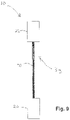
- FIG. 9 is an enlarged end view of a roof or floor truss module
- FIG. 10 is a perspective view illustrating a multiplicity of roof or floor truss modules installed on a pair of parallel support walls;
- FIG. 11 is an enlarged side view of a fastener which may be employed in any of the roof or floor truss modules;
- FIG. 12 is a schematic diagram illustrating the various possible fastener orientations for fasteners employed in various roof truss modules
- FIG. 13 A is a side elevational view, partly in schematic, of a prior art shear wall diagram
- FIG. 13 B is a side elevational view of a prior art wall diagram illustrating non-shear characteristics upon an application of a lateral force
- FIG. 14 is a side elevational view of a shear wall incorporating installed shear panels comprising structural truss modules employing a web of fasteners;
- FIG. 15 is a side elevational view illustrating structural truss modules employed as vertical shear panels in a wall
- FIG. 16 is a perspective view of a wall incorporating shear panels comprising the structural truss modules of FIG. 15 ;
- FIG. 17 is a side elevational view illustrating an installed header comprising a structural truss module with a web of fasteners
- FIG. 18 is a perspective view of the header wall assembly of FIG. 17 ;
- FIGS. 19 A- 19 D are annotated schematic views illustrating a representative manufacturing process for a representative structural truss module
- FIGS. 20 A- 20 D are representative perspective views of structural truss modules with a single web configuration, a double web configuration, a triple web configuration and a quadruple web configuration, respectively;
- FIG. 21 is a perspective view of a modular building structure incorporating features of the present disclosure.
- FIG. 22 is a perspective view of a prior art decking structure
- FIG. 23 is a perspective view of a ledger, carrying beam truss modules, support posts, and footings used in the modular building structure shown in FIG. 21 ;
- FIG. 24 is a perspective view of arranged structural truss modules the modular building structure shown in FIG. 21 ;
- FIG. 25 is a side view of a portion the modular building structure shown in FIG. 21 further illustrating a carrying beam truss module;
- FIG. 26 is a side view of a portion the modular building structure shown in FIG. 21 further illustrating attachment to a ledger;
- FIG. 27 is a side view of the modular building structure with an alternate arrangement for the carrying beam truss module
- FIG. 28 is a perspective view illustrating insertion of a blocking member used in the modular building structure shown in FIG. 21 ;
- FIG. 29 is a perspective view illustrating insertion of a cross bracing blocking member used in the modular building structure shown in FIG. 21 ;
- FIG. 30 is a perspective view illustrating attaching of rim fascia members used in the modular building structure shown in FIG. 21 ;
- FIG. 31 is a front view of one of the rim fascia members (attached to a structural truss module) shown in FIG. 30 ;
- FIG. 32 is a perspective view of a structural truss module having a grooved top chord
- FIG. 33 is a side view of a structural truss module (with illustrated cut lines) used in the modular building structure shown in FIG. 21 ;
- FIG. 34 is a perspective view of delivered materials used in the modular building structure shown in FIG. 21 ;
- FIG. 35 is a block diagram of an exemplary method of the present disclosure.
- FIG. 36 is a block diagram of another exemplary method of the present disclosure.
- FIG. 37 is a block diagram of another exemplary method of the present disclosure.
- FIG. 38 is a perspective view of a preassembled modular deck incorporating features of the present disclosure.
- FIG. 39 is a side view of an alternate embodiment of the modular building structure shown in FIG. 21 illustrating portions of the structural truss module.
- FIG. 40 is a side view of an alternate embodiment of the modular building structure shown in FIG. 21 illustrating the carrying beam truss module between chords of the structural truss module.
- a structural truss module is generally designated by the numeral 10 .
- the structural truss module 10 can be constructed in a wide range of sizes and can provide a number of structural functions in an integrated construction, such as for a roof or floor truss assembly 100 illustrated in FIG. 10 , a reinforced structural shear wall 200 illustrated in FIGS. 15 and 16 and a header structure for a wall 300 illustrated in FIGS. 17 and 18 .
- the structural roof or floor truss module 10 can be selectively configured in a number of standard heights H, such as 71 ⁇ 4, 91 ⁇ 2, 117 ⁇ 8, 14, 16 and 18 inches, and various lengths L as dictated by a given application.
- the structural truss module 10 in accordance with the present disclosure, allows for the ability to custom construct the module having specific dimensions as required.
- the structural truss module 10 functions as a ready replacement for a dimensional lumber-type floor joist as represented in FIG. 1 A , an I-joist such as represented in FIG. 2 B , or an open web roof or floor truss assembly such as represented in FIG. 1 C .
- the features of the structural truss assembly allow for construction of the structural truss module as required and allow for efficiencies over a prior art representative load of stacked roof trusses, such as illustrated in FIG. 1 D , by effectively replacing the latter with a compact load of wood chords and a pallet of fasteners, as will be described below.
- a representative structural truss module 10 suitable for a truss is constructed from a pair of wood chords 20 and 22 which are joined by a web 30 comprising a matrix of metal fasteners 40 .
- the chords may be 2 ⁇ 3, 2 ⁇ 4 or other structural lumber components having a desired length L.
- the fasteners 40 are dimensioned in accordance with the desired height H of the truss.
- the fasteners 40 are preferably identical although identical fasteners are not required.
- the lengths L of the chords are preferably equal although equal lengths for chords 20 and 22 are not required.
- the chords need not be oriented in the 2 ⁇ direction as illustrated, but may essentially assume a 3 ⁇ 2 or 4 ⁇ 2 orientation.
- the fasteners 40 are elongated screws having a head 42 for receiving a high drive torque, a first threaded portion 44 generally adjacent the head, an unthreaded medial portion 45 , a second threaded portion 46 adjacent the distal end, and a tip 48 which facilitates penetration into the wood chords.
- the fasteners 40 are oriented at an angle of approximately 45° to the chord 20 , and are drilled from the bottom chord 20 to the top chord 22 at the pre-determined angle.
- the first threaded portion 44 threadably engages the lower chord 20 and the second threaded portion 46 threadably engages the upper chord 22 .
- the thread tips 48 preferably terminate approximately one inch to one and a half inches below the upper edge of chord 22 .
- a pilot bore 21 is pre-formed in the chord 20 at the given angle for each fastener.
- the fastener matrix comprises a series of fastener pairs 50 .
- the fastener of each pair is oriented so that the central axes of the fasteners essentially intersect at the top edge 24 of chord 22 ( FIG. 7 ).
- the fastener tips 48 never engage. It is desired that the head 42 be seated below the bottom edge 26 of chord 20 approximately at a one inch to a one and a half inch spacing from the edge. For a given chord, the spacing is preferably uniform.
- the fasteners are driven and disposed on the center lines of the chords and generally transversely aligned along the length of the chord.
- one fastener 40 is driven at a vertical angle or 90° angle to the chords.
- a representative manufacturing method for a representative structural truss module 510 is schematically illustrated in FIGS. 19 A- 19 D .
- a jig assembly 500 employs a reference shoulder 502 and a plurality of jigs 504 for securing a first chord 522 at a fixed position.
- a second set of jigs 506 secure a substantially identical second chord 520 at an opposed second position equidistantly spaced from the first chord.
- Multiple guides 508 are disposed in fixed position between the chords to provide the proper entry angle for the fasteners 540 .
- the guides 508 are angularly adjustable and adapted to be fixed at the selected angular position.
- a drill 515 or a series of drills 515 are activatable to drill a pilot bore in the bottom chord 520 at the given angles illustrated. It will be appreciated that some of the pilot bore formations are done sequentially because of the angular relationships of the pilot bores for the truss module 510 .
- a first set of fasteners 540 is installed by a torque driver 517 driving the fasteners through the pilot bores at a first angle, and at a right angle on one end as illustrated so that the fasteners 540 are threadably engaged in the first chord 522 and threadably embedded in the second or bottom chord 520 .
- the driving of the fasteners can be done concurrently.
- the head 542 of each fastener is driven into the chord 520 a pre-established distance from the edge 526 .
- the end fasteners may have a shorter length than the fasteners driven at an angle.
- Fasteners 540 preferably have substantially the same geometry as fasteners 40 .
- a second set of fasteners is then driven through the other pilot bores and the 90° pilot bore so that the head 542 of each fastener is embedded in the second chord and the fasteners threadably engage the first chord.
- the driving of the second set of fasteners 540 may be accomplished concurrently.
- the constructed truss module 510 is then removed from the jigs.
- the finished structural truss module 510 is illustrated in FIG. 19 D .
- the vertically oriented fastener is driven initially through the bottom edge 26 .
- the next fastener in the web array is initially driven through the top edge 24 and the third fastener in the web array is initially driven through the bottom edge 26 .
- the fasteners may be driven from the same edge or non-alternating edges.
- the fasteners may be driven at various angles and orientations relative to the chords, as schematically suggested in FIG. 12 .
- the web is formed by a series of angled quasi-convergent pairs 50 of fasteners.
- FIG. 11 Another suitable fastener 40 ′ is illustrated in FIG. 11 and comprises a drive head 42 which receives a drive torque, a threaded portion 44 ′ adjacent the head and a second threaded portion 46 ′ adjacent the distal end extending to the tip 48 ′.
- a medial portion 45 ′ of substantial extent is not threaded.
- the unthreaded portion 45 ′ extends a greater distance than that of portion 45
- the threaded portions 44 ′ and 46 ′ extend a smaller distance than threaded portions 44 and 46 .
- Other fasteners may be employed.
- the fasteners for a given truss module need not be identical.
- single, double, triple and quadruple representative structural truss module embodiments are shown as 610 A, 610 B, 610 C and 610 D, respectively.
- an array of single fasteners 640 is employed and the fasteners preferably connect the wood chords 620 and 622 along a medial transverse line l of the chords.
- Structural truss module 6106 employs groups 651 , 652 , 653 , 654 . . . of pairs of parallel fasteners 640 which are preferably equidistantly threaded into the chords 620 and 622 at locations which are equidistantly spaced from a longitudinal medial line l through the chords.
- Structural truss module 610 C employs groups 661 , 662 , 663 , 664 . . . of three parallel fasteners 640 .
- a medial set of the fasteners engages the chords 620 and 622 at spaced locations along a medial line l.
- a second set of the fasteners are equidistantly spaced from the medial line and longitudinally offset from the first set, as illustrated.
- structural truss module 610 D employs groups 671 , 672 , 673 , 674 . . . of four fasteners 640 .
- Each of the groups of fasteners preferably engages the chords equidistantly spaced from the medial line l of the chords.
- a given truss module may employ one or more groups of two, three, four or a single fastener in a given truss module to provide the requisite structural strength.
- the illustrated modules 610 A, 610 B, 610 C and 610 D are intended to be representative and typically are longer and have many more fastener groups than depicted.
- the fasteners 640 preferably have a geometry substantially similar to fasteners 40 or 40 ′.
- the structural truss modules 10 , 510 , 610 A and 610 D have a number of features. Each module is relatively open and consequently provides enhanced space for accommodating mechanical and electrical systems.
- the metal fasteners combine to implement a construction which has a high degree of structural integrity.
- the structural truss modules 10 have superior fire damage characteristic by virtue of a favorable anti-burn rate since the web connection, which provides the principal support, is the last structure to be adversely impacted by fire.
- the structural truss modules 10 , 510 , 610 A and 610 D have a very favorable weight and provide enhanced storage capabilities since the components are essentially the chords plus the fasteners, and the various extra weight and storage requirements for the additional wood components characteristic of conventional truss construction are not present.
- the fastener web 30 construction is relatively straightforward and can be accomplished in an efficient custom manner which lends itself to essentially just-in-time construction.
- the fastener web structure provides a conducive structure for attaching the various electrical plumbing and mechanical components by plastic ties and other efficient low cost mounting hardware.
- the disclosed structural truss modules are also greener in the sense that the only wood required for the module is the chords.
- the structural truss modules have favorable cost characteristics because the fastening components are typically less expensive than the conventional wood/lumber support components. In addition, the manufacturing process is less labor intensive.
- the structural truss components can be constructed in various lengths such as, for example, a smaller length for structural truss module 10 a illustrated in FIG. 6 , and in various configurations such as the flat truss 10 b of FIG. 3 as mounted to support walls 60 .
- the structural truss modules 10 also have applicability as reinforcing panels for shear walls 200 .
- the modules are oriented vertically.
- FIGS. 13 A and 13 B illustrate a prior art conventional shear wall which, upon subject to a lateral force, such as wood, tends to rotate.
- the incorporation of the structural truss modules reinforces the wall and tends to make the wall resistant to application of a lateral shear force and consequent rotation as illustrated in FIG. 13 B .
- FIGS. 15 and 16 illustrate an alternative implementation of the structural truss module 10 to construct the shear wall 200 .
- the structural truss module 10 also can be employed as a header over a window or doorway 310 or other structure for wall 300 .
- the module has a horizontal orientation.
- the construction of the module can be custom completed for a given construction application.
- the header provides enhanced support. Due to its openness, the structural truss module 10 header provides improved thermal capabilities by enhancing the insulation and airtightness of the construction as a consequence of inserting insulation materials into the open structure of the module.
- truss modules 610 A- 610 D may also be employed for support walls, shear walls and headers.
- the structure 700 may be a house, building, or any other structure capable of having a deck or platform extend therefrom.
- the modular deck (or modular building structure) 1000 is formed from a plurality of truss modules 810 (best seen in FIG. 24 ) which serve a similar function as joists in a conventional deck configuration.
- the modular deck 1000 (comprising the plurality of truss modules 810 ) provides a replacement configuration for conventional joist and blocking decking arrangements (see FIG. 22 ).
- the joist and blocking arrangements for conventional deck structures generally includes joists which are connected to a ledger by joist hangers, and blocking (between the joists) which is provided by several separate members installed between the joists.
- the conventional joists generally comprise dimensional lumber sizes of 2 ⁇ 6, 2 ⁇ 8, 2 ⁇ 10, or 2 ⁇ 12, and the blocking comprises suitably sized dimensional lumber fitted between the joists.
- the features of the modular deck 1000 allow for faster assembly/construction, increased durability, and other efficiencies over the conventional configurations, as will be described below.
- Each one of the structural truss modules 810 is similar to the structural truss module 10 such that the lower chord 820 , the upper chord 822 , and the fasteners 840 are substantially the same as the lower chord 20 , the upper chord 22 , and the fasteners 40 .
- the structural truss modules 810 are preassembled at a manufacturing facility or other suitable location capable of assembling the structural truss modules as described above.
- modular deck 1000 has been described in connection with the truss module 810 (which is similar to the truss module 10 ), it should be noted that in alternate embodiments the modular deck may comprise any other suitable structural truss module (such as the truss modules 510 , 610 A, 610 B, 610 C, 610 D, for example).
- the modular deck 1000 comprises rim fascia members 1010 , 1010 a , decking members 1012 , outer fascia members 1014 , and blocking members 1016 , 1016 a .
- the modular deck is configured to be attached to a ledger 1018 and is supported by one or more carrying beam truss modules 910 which are attached to support posts 1020 and corresponding footings 1022 .
- each one of the carrying beam truss modules 910 is similar to the ‘double fastener’ structural truss module 610 B such that the lower chord 920 , the upper chord 922 , and the fasteners 940 are substantially the same as the lower chord 620 , the upper chord 622 , and the fasteners 640 .
- the carrying beam truss modules 910 are preassembled at a manufacturing facility or other suitable location capable of assembling the carrying beam modules as described above.
- the carrying beam truss modules 910 are attached to the support posts 1020 which are secured to the footings 1022 . According to some embodiments, the carrying beam truss modules 910 may be temporarily attached to the support posts 1020 during assembly of the deck 1000 such as to allow for spacing of the structural truss modules 810 (with the carrying beam truss modules 910 securely attached [with suitable fasteners, for example] to the support posts 1020 upon completion of assembly).
- the ledger 1018 provides a mounting and support area between the structure 700 and the deck 1000 .
- the carrying beam truss modules 910 provide support for the remainder of the deck at spaced intervals from the ledger 1018 .
- carrying beam truss modules 910 (which are similar to the truss module 610 B) are provided as shown in FIG. 23 , however in other embodiments any suitable type of truss module may be provided (such as truss modules 10 , 510 , 610 A, 610 C, 610 D, for example). Additionally, although FIG. 23 shows two carrying beam truss modules for supporting the deck, any suitable number of carrying beam truss modules (such as one or three, for example) may be provided for supporting the deck.
- the preassembled structural truss modules 810 are arranged in a general parallel fashion and are spaced apart at about 12-24 inches similar to conventional joists (see FIG. 24 ).
- the structural truss modules 810 are substantially perpendicular to the carrying beam truss modules 910 which are suitably spaced from each other.
- the structural truss modules 810 are arranged such that lower chords 920 and upper chords 922 of the carrying beam truss modules 910 extend between the lower chords 820 and the upper chords 822 of the structural truss modules 810 (as best seen in FIGS. 24 and 25 ).
- First ends 812 of the structural truss modules 810 are directly attached to the ledger 1018 such that the leger is received between the bottom chords 820 and the upper chords 822 (best seen in FIG. 26 ). With this configuration, the chords 820 , 822 can be secured to the ledger 1018 by any suitable fastener (without the need for a joist hanger).
- the carrying beam truss modules 910 Support for the remaining length of the structural truss modules 810 extending from the leger 1018 is provided by the carrying beam truss modules 910 .
- FIG. 24 shows the carrying beam truss modules 910 extending between the chords 820 , 822 of the truss modules 810
- alternate embodiments may comprise one or more of carrying beam truss modules 910 below the structural truss modules 810 as shown in FIG. 27 .
- a portion of the bottom surfaces of the lower chords 820 of the structural truss modules 810 rest on a top surface of the upper chord 922 of the carrying beam truss module 910 .
- each blocking member 1016 may be provided between the fasteners 840 such that each blocking member is received between the bottom chords 820 and the upper chords 822 of the structural truss modules 810 . Similar to conventional blocking (as shown in FIG. 22 ), the blocking members 1016 provide additional support to stiffen the deck 1000 .
- each blocking member may be an integral one piece member, suitably sized and shaped to extend in a substantially perpendicular orientation relative to the structural truss modules.
- one or more of the blocking members may be provided at an angled orientation relative to the structural truss modules.
- FIG. 29 shows a blocking member 1016 a extending between the fasteners 840 but angled relative to the structural truss modules 810 .
- the blocking member 1016 a comprises an integral one piece member suitably sized and shaped to extend between the lower chords 820 and the upper chords 822 of the structural truss modules 810 .
- the rim fascia members 1010 , 1010 a extend between the lower chords 820 and the upper chords 822 of the structural truss modules 810 proximate outer edges of the modular deck 1000 .
- One of the rim fascia members 1010 extends between the chords 820 , 822 at second ends 814 of the structural truss modules 810 such that the rim fascia member 1010 is perpendicular to the structural truss modules and opposite the ledger (see FIG. 30 ).
- the other rim fascia members 1010 a extend between the chords 820 , 822 such that the rim fascia members 1010 a are parallel to the structural truss modules 810 and adjacent to the fasteners 840 such that top and bottom sides of the rim fascia members are between the chords (see FIGS. 30 , 31 ).
- the decking members 1012 are attached to the top side of the top chords by screws or by any other suitable fastening method.
- the decking members 1012 are generally arranged to be perpendicular to the structural truss modules 810 , however any suitable arrangement may be provided.
- the decking members 1012 are attached to the top side of the top chords 1022 by a decking bracket or any other suitable complementary hardware or fastener (not shown).
- the top chords 1022 comprise grooves 823 configured to receive portions of the decking bracket (see FIG. 32 ).
- the outer fascia members 1014 are attached over the rim fascia members by screws or any other suitable fastening method.
- the structural truss modules 810 are preassembled and may be provided as a standard size, or may be cut to size (if needed) corresponding to the particular size required for the application (such as deck, for example).
- the preassembly and/or cutting of the structural truss modules may be performed at a manufacturing facility or other suitable location capable of assembling and/or cutting the truss modules as described above.
- the structural truss modules can be delivered to the job site as a standard size and then cut to a custom size at the job site. For example see FIG. 33 which shows various cut lines (shown as dashed vertical lines along a length L) illustrating various locations along the length of the structural truss module where the structural truss module can be cut to the desired size. It should be noted that some embodiments may comprise vertical fasteners at opposite ends of the structural truss modules, however any suitable fastener configuration may be provided.
- FIG. 34 illustrates exemplary delivered materials may be provided to a job site (which includes the decking components shown in FIG. 1 in a compact and delivered configuration).
- the structural truss modules may be already cut to size in a manufacturing facility, in other embodiments the structural truss modules may be a standard length which can be cut to size at the job site.
- the method 1100 includes attaching a ledger to a structure (at block 1102 ). Placing footings at desired locations for suitable support to the modular deck (at block 1104 ). Installing one or more carrying beam truss modules (at block 1106 ). Installing structural truss modules (at block 1108 ). Inserting blocking (at block 1110 ). Inserting cross bracing blocking (at block 1112 ). Installing rim fascia (at block 1114 ). Attaching composite decking (at block 1116 ). Installing composite fascia (at block 1118 ). It should be noted that the illustration of a particular order of the blocks does not necessarily imply that there is a required or preferred order for the blocks and the order and arrangement of the blocks may be varied. Furthermore it may be possible for some blocks to be omitted.
- FIG. 36 illustrates another exemplary method 1200 .
- the method 1200 includes providing a plurality of structural truss modules (at block 1202 ).
- Each one of the structural truss modules comprises a spaced pair of generally parallel elongated wood chords and a web connecting said elongated wood chords, said web comprising a plurality of metal support rods each having a pair of opposed threaded sections, the first of the pair of opposed threaded sections engaged to a first one of the elongated wood chords at an angle thereto, and the second of the pair of opposed threaded sections engaged to the other one of the elongated wood chords at an angle thereto.
- Cutting the structural truss modules to a predetermined length (at block 1204 ).
- the structural truss modules Arranging the structural truss modules with the wood chords substantially flat and adjacent one another (at block 1206 ).
- the structural truss modules are substantially evenly spaced in a generally parallel orientation. Connecting a first member between the spaced pairs of elongated wood chords of the plurality of structural truss modules (at block 1208 ). First ends of the plurality of structural truss modules are configured to connect to a ledger member. It should be noted that the illustration of a particular order of the blocks does not necessarily imply that there is a required or preferred order for the blocks and the order and arrangement of the blocks may be varied. Furthermore it may be possible for some blocks to be omitted. Additionally, various features described below may be included in the method.
- the first member comprises a blocking member.
- the first member comprises a fascia member.
- the first member comprises a carrying beam truss member.
- the method above wherein the method further comprises connecting the ledger member between the spaced pairs of elongated wood chords at the first ends of the plurality of structural truss modules.
- At least one of the plurality of structural truss modules comprises a fascia member between the spaced pair of elongated wood chords, wherein the fascia member is substantially parallel to the spaced pair of elongated wood chords.
- the method above further comprising connecting a blocking member to the plurality of structural truss modules by installing the blocking member between the spaced pairs of elongated wood chords of the plurality of structural truss modules.
- connecting the blocking member to the plurality of structural truss modules further comprises installing the blocking member between adjacent fasteners of the plurality of fasteners.
- connecting the blocking member to the plurality of structural truss modules further comprises installing the blocking member between adjacent angled pilot bores of the elongated wood chords.
- the method above further comprising providing a carrying beam truss module; cutting the carrying beam truss module to a predetermined length; and attaching the carrying beam truss module to the plurality of structural truss modules.
- the carrying beam truss module comprises a spaced pair of elongated wood chords and a web connecting said elongated wood chords, said web comprising a plurality of metal support rods each having a pair of opposed threaded sections, the first of the pair of opposed threaded sections engaged to a first one of the elongated wood chords at an angle thereto, and the second of the pair of opposed threaded sections engaged to the other one of the elongated wood chords at an angle thereto.
- FIG. 37 illustrates another exemplary method 1300 .
- the method 1300 includes providing a first preassembled structural truss module (at block 1302 ).
- the first preassembled structural truss module comprises a first elongated support beam, a second elongated support beam, and a web connecting said elongated support beams, said web comprising a plurality of rods each having a pair of opposed threaded sections, wherein the first elongated support beam is generally parallel to the second elongated support beam, wherein the first elongated support beam comprises a first surface, a second surface, and a plurality of fastener openings extending between the first surface and the second surface, wherein a first one of the opposed threaded sections is threadably engaged with a portion of one of the plurality of openings of the first elongated support beam, wherein a second one of the opposed threaded sections is threadably engaged with the second elongated support beam.
- the second preassembled structural truss module comprises a first elongated support beam, a second elongated support beam, and a web connecting said elongated support beams, said web comprising a plurality of rods each having a pair of opposed threaded sections, wherein the first elongated support beam is generally parallel to the second elongated support beam, wherein the first elongated support beam comprises a first surface, a second surface, and a plurality of fastener openings extending between the first surface and the second surface, wherein each rod comprises opposed threaded sections, wherein a first one of the opposed threaded sections is threadably engaged with a portion of one of the plurality of openings of the first elongated support beam, wherein a second one of the opposed threaded sections is threadably engaged with the second elongated support beam.
- Cutting the first preassembled structural truss module at a predetermined length between the plurality of fastener openings (at block 1306 ).
- Cutting the second preassembled structural truss module at a predetermined length between the plurality of fastener openings (at block 1308 ).
- Securing a first member between the first elongated support beam and the second elongated support beam of the first preassembled structural truss module (at block 1310 ).
- Securing the first member between the first elongated support beam and the second elongated support beam of the second preassembled structural truss module (at block 1312 ).
- the first surface of the first elongated support beam of the first preassembled structural truss module is substantially coplanar with the first surface of the first elongated support beam of the second preassembled structural truss module.
- the method above further comprising: securing a second member between the first elongated support beam and the second elongated support beam of the first preassembled structural truss module; and securing the second member between the first elongated support beam and the second elongated support beam of the second preassembled structural truss module.
- first elongated support beams and the second elongated support beams comprise 2 ⁇ 3 wood chords, 2 ⁇ 4 wood chords, or engineered wood components.
- a modular building structure comprising: a plurality of structural truss modules, wherein each one of the structural truss modules comprises a spaced pair of elongated wood chords and a web connecting said elongated wood chords, said web comprising a plurality of metal support rods each having a pair of opposed threaded sections, the first of the pair of opposed threaded sections engaged to a first one of the elongated wood chords at an angle thereto, and the second of the pair of opposed threaded sections engaged to the other one of the elongated wood chords at an angle thereto, wherein the spaced pair of elongated wood chords are generally parallel to each other, and wherein each one of the plurality of structural truss modules is substantially evenly spaced from each other and arranged in a generally parallel orientation; a first member extending between the spaced pair of elongated wood chords of the plurality of structural truss modules; and a second member extending between the spaced pair of
- the modular deck 1000 can be “pre-assembled” (such that the structural truss modules 810 , one or more blocking members 1016 , rim fascia 1010 , and/or one or more carrying beam truss modules 910 are assembled together as described above) at the manufacturing facility and then attached to the ledger and support posts/footings at the job site.
- FIGS. 39 and 40 there is shown an embodiment having an alternate interface between the carrying beam truss module 910 and the structural truss modules 810 .
- the structural truss modules 810 are still arranged such that lower chords 920 and upper chords 922 of the carrying beam truss modules 910 extend between the lower chords 820 and the upper chords 822 of the structural truss modules 810 , however in this embodiment the structural truss modules 810 each comprise recessed surfaces 819 , 821 which are sized and shaped to receive the carrying beam truss module.
- Each recessed surface 819 , 821 extends in a direction perpendicular to the structural truss module and is sized and shaped to receive the lower and upper chords 920 , 922 of the carrying beam truss module 910 . It should be noted that although FIGS. 39 and 40 illustrate an embodiment where the structural truss module has recessed surfaces configured to receive one carrying beam truss module, alternate embodiments may comprise additional recessed surfaces for any suitable number of carrying beam truss modules.
- the structural truss modules, the carrying beam truss modules, rim fascia members, decking members, outer fascia members, and blocking members may comprise any suitable material.
- these may all be wood, composite, engineered wood components, etc., or any combination thereof.
- the modular deck provides various advantages such as added ease and less labor intensive deck construction and faster assembly times.
Landscapes
- Engineering & Computer Science (AREA)
- Architecture (AREA)
- Civil Engineering (AREA)
- Structural Engineering (AREA)
- Physics & Mathematics (AREA)
- Electromagnetism (AREA)
- Life Sciences & Earth Sciences (AREA)
- Wood Science & Technology (AREA)
- Chemical & Material Sciences (AREA)
- Composite Materials (AREA)
- Joining Of Building Structures In Genera (AREA)
- Rod-Shaped Construction Members (AREA)
Abstract
Description
Claims (17)
Priority Applications (1)
| Application Number | Priority Date | Filing Date | Title |
|---|---|---|---|
| US16/906,435 US11519174B2 (en) | 2015-08-26 | 2020-06-19 | Building structure formed by truss modules and method of forming |
Applications Claiming Priority (3)
| Application Number | Priority Date | Filing Date | Title |
|---|---|---|---|
| US201562210026P | 2015-08-26 | 2015-08-26 | |
| US15/248,069 US11236507B2 (en) | 2015-08-26 | 2016-08-26 | Structural truss module with fastener web and manufacturing method therefor |
| US16/906,435 US11519174B2 (en) | 2015-08-26 | 2020-06-19 | Building structure formed by truss modules and method of forming |
Related Parent Applications (1)
| Application Number | Title | Priority Date | Filing Date |
|---|---|---|---|
| US15/248,069 Continuation-In-Part US11236507B2 (en) | 2015-08-26 | 2016-08-26 | Structural truss module with fastener web and manufacturing method therefor |
Publications (2)
| Publication Number | Publication Date |
|---|---|
| US20200385990A1 US20200385990A1 (en) | 2020-12-10 |
| US11519174B2 true US11519174B2 (en) | 2022-12-06 |
Family
ID=73651265
Family Applications (1)
| Application Number | Title | Priority Date | Filing Date |
|---|---|---|---|
| US16/906,435 Active 2036-11-05 US11519174B2 (en) | 2015-08-26 | 2020-06-19 | Building structure formed by truss modules and method of forming |
Country Status (1)
| Country | Link |
|---|---|
| US (1) | US11519174B2 (en) |
Cited By (1)
| Publication number | Priority date | Publication date | Assignee | Title |
|---|---|---|---|---|
| US20210395993A1 (en) * | 2020-06-19 | 2021-12-23 | Fred A. Wagner, III | Modular decking system |
Families Citing this family (1)
| Publication number | Priority date | Publication date | Assignee | Title |
|---|---|---|---|---|
| EP3908709A1 (en) * | 2019-01-13 | 2021-11-17 | Simpson Strong-Tie Company, Inc. | Ledger connector |
Citations (40)
| Publication number | Priority date | Publication date | Assignee | Title |
|---|---|---|---|---|
| US852665A (en) | 1906-11-12 | 1907-05-07 | Charles H Kellogg | Separator for girders. |
| US1554224A (en) * | 1922-08-04 | 1925-09-22 | Thomas B Mcgrath | Fuselage structure |
| FR865513A (en) | 1940-05-09 | 1941-05-26 | Wood assembly | |
| US2342916A (en) | 1942-10-26 | 1944-02-29 | John F Blaski | Arched wooden rafter |
| US3778946A (en) * | 1970-12-21 | 1973-12-18 | Woodco Ltd | Truss and method of making same |
| US3961455A (en) | 1973-05-29 | 1976-06-08 | Peters Dierk D | Truss support connector |
| US4069635A (en) * | 1977-01-10 | 1978-01-24 | Simpson Manufacturing Co., Inc. | Truss structure with clevis assembly joints |
| US4173857A (en) * | 1977-11-22 | 1979-11-13 | Yoshiharu Kosaka | Double-layered wooden arch truss |
| US4282619A (en) * | 1979-11-16 | 1981-08-11 | Havens Steel Company | Truss structure |
| US4653244A (en) | 1986-01-16 | 1987-03-31 | Farrell Mark A | Fastener element |
| US4819400A (en) | 1985-03-22 | 1989-04-11 | Bjorn Larsson | Beam and method for the production thereof |
| EP0448915A1 (en) | 1990-03-28 | 1991-10-02 | SFS Handels Holding AG | Construction method for an under-roof, under-roof built according to this method, and screw for the execution of the method |
| US5301487A (en) | 1991-03-29 | 1994-04-12 | Wiebe Jacob R | Wooden structural member for use in a building |
| US5644888A (en) * | 1993-01-21 | 1997-07-08 | Ebert Composites Corporation | Heavy construction system using composite members |
| US5746039A (en) | 1996-05-31 | 1998-05-05 | Metaltite Corporation | Truss fastener and truss assembly |
| US5816012A (en) | 1997-03-10 | 1998-10-06 | Alpine Engineered Products, Inc. | Dual threaded fastener and metal component assembly |
| US6074149A (en) | 1999-06-30 | 2000-06-13 | G. Lyle Habermehl | False threadscrew and screwstrip |
| US6243996B1 (en) * | 1998-11-05 | 2001-06-12 | James Oliver | Adjustable truss for mating seam of multi-section manufactured home |
| US6325583B1 (en) | 1997-09-22 | 2001-12-04 | Sfs Industrie Holding Ag | Screw for fixing wooden laths on a roof substructure or a wall foundation |
| US6427403B1 (en) * | 1998-11-03 | 2002-08-06 | Nicholas C. Tambakis | Fiber reinforced plastic (FRP) composite structural system for decks, docks, boardwalks, walkways, spa decks, hot tub decks and gazebos and components therefore and method of making same |
| DE10202497A1 (en) | 2001-01-30 | 2002-10-02 | Thomas Sohm | Plate element used as a ceiling or wall element comprises boards or beams arranged edgewise and connected by wooden dowels |
| US6688059B1 (en) * | 2002-12-06 | 2004-02-10 | Kenneth E. Walker | Protective trim strip for decks |
| US20040226252A1 (en) * | 2003-05-15 | 2004-11-18 | Sheldon Forrest W. | System for enhancing the durability of wood construction |
| US20040255551A1 (en) * | 2003-01-30 | 2004-12-23 | Fuhr John Christopher | Flat deck apparatus and method |
| US20050252152A1 (en) | 2004-05-12 | 2005-11-17 | Belinda Richard L | Steel truss fasteners for multi-positional installation |
| US20060201581A1 (en) | 2005-03-10 | 2006-09-14 | Richard Belinda | Timber fastener and method of manufacturing and employing the same |
| US7150132B2 (en) | 2003-08-12 | 2006-12-19 | Commins Alfred D | Continuous hold-down system |
| US20080245030A1 (en) | 2005-05-19 | 2008-10-09 | Sfs Intec Holding Ag | Building Wall Structure |
| US7695228B2 (en) | 2001-02-15 | 2010-04-13 | Phillips Fastener, Llc | Screw |
| US20100180540A1 (en) * | 2009-01-16 | 2010-07-22 | Mark Shepard | Hybrid Top Chord Bearing Framing System |
| US7832173B2 (en) | 1996-10-01 | 2010-11-16 | Simpson Strong-Tie Company, Inc. | Screw fastener in multiple floor truss and wood-to-wood shear connection |
| EP2256262A1 (en) | 2009-10-22 | 2010-12-01 | Naturbau Gschwend Geschwendbau GmbH | Wood structure module, method for its manufacture and application |
| US8656650B2 (en) | 2009-03-23 | 2014-02-25 | Simpson Strong-Tie Company Inc. | Take-up fastener for resisting uplift loads in light framed construction |
| US8739489B2 (en) * | 2008-01-18 | 2014-06-03 | Sigma Dek Ltd. | Decking system |
| US20140174017A1 (en) * | 2012-12-24 | 2014-06-26 | Whole Trees, LLC | Truss and column structures incorporating natural round timbers and natural branched round timbers |
| US20140338279A1 (en) * | 2013-03-14 | 2014-11-20 | Scott F. Armbrust | Tubular joist structures and assemblies and methods of using |
| US20160194869A1 (en) | 2013-09-06 | 2016-07-07 | Loggo Ip Pty Ltd In Its Capacity As Trustee For Thornton Ip Trust | Composite structural member |
| US9822521B1 (en) * | 2016-07-01 | 2017-11-21 | Chingyao Kuo | Assembly outdoor balcony |
| US20180094435A1 (en) * | 2014-03-14 | 2018-04-05 | Scott F. Armbrust | Tubular joist structures and assemblies and methods of using |
| US20180135316A1 (en) * | 2015-10-06 | 2018-05-17 | Paul Kristen, Inc. | Platform and a kit therefor |
-
2020
- 2020-06-19 US US16/906,435 patent/US11519174B2/en active Active
Patent Citations (45)
| Publication number | Priority date | Publication date | Assignee | Title |
|---|---|---|---|---|
| US852665A (en) | 1906-11-12 | 1907-05-07 | Charles H Kellogg | Separator for girders. |
| US1554224A (en) * | 1922-08-04 | 1925-09-22 | Thomas B Mcgrath | Fuselage structure |
| FR865513A (en) | 1940-05-09 | 1941-05-26 | Wood assembly | |
| US2342916A (en) | 1942-10-26 | 1944-02-29 | John F Blaski | Arched wooden rafter |
| US3778946A (en) * | 1970-12-21 | 1973-12-18 | Woodco Ltd | Truss and method of making same |
| US3961455A (en) | 1973-05-29 | 1976-06-08 | Peters Dierk D | Truss support connector |
| US4069635A (en) * | 1977-01-10 | 1978-01-24 | Simpson Manufacturing Co., Inc. | Truss structure with clevis assembly joints |
| US4173857A (en) * | 1977-11-22 | 1979-11-13 | Yoshiharu Kosaka | Double-layered wooden arch truss |
| US4282619A (en) * | 1979-11-16 | 1981-08-11 | Havens Steel Company | Truss structure |
| US4819400A (en) | 1985-03-22 | 1989-04-11 | Bjorn Larsson | Beam and method for the production thereof |
| US4653244A (en) | 1986-01-16 | 1987-03-31 | Farrell Mark A | Fastener element |
| EP0448915A1 (en) | 1990-03-28 | 1991-10-02 | SFS Handels Holding AG | Construction method for an under-roof, under-roof built according to this method, and screw for the execution of the method |
| US5301487A (en) | 1991-03-29 | 1994-04-12 | Wiebe Jacob R | Wooden structural member for use in a building |
| US5644888A (en) * | 1993-01-21 | 1997-07-08 | Ebert Composites Corporation | Heavy construction system using composite members |
| US5746039A (en) | 1996-05-31 | 1998-05-05 | Metaltite Corporation | Truss fastener and truss assembly |
| US7832173B2 (en) | 1996-10-01 | 2010-11-16 | Simpson Strong-Tie Company, Inc. | Screw fastener in multiple floor truss and wood-to-wood shear connection |
| US5816012A (en) | 1997-03-10 | 1998-10-06 | Alpine Engineered Products, Inc. | Dual threaded fastener and metal component assembly |
| US6325583B1 (en) | 1997-09-22 | 2001-12-04 | Sfs Industrie Holding Ag | Screw for fixing wooden laths on a roof substructure or a wall foundation |
| US6427403B1 (en) * | 1998-11-03 | 2002-08-06 | Nicholas C. Tambakis | Fiber reinforced plastic (FRP) composite structural system for decks, docks, boardwalks, walkways, spa decks, hot tub decks and gazebos and components therefore and method of making same |
| US6243996B1 (en) * | 1998-11-05 | 2001-06-12 | James Oliver | Adjustable truss for mating seam of multi-section manufactured home |
| US6074149A (en) | 1999-06-30 | 2000-06-13 | G. Lyle Habermehl | False threadscrew and screwstrip |
| DE10202497A1 (en) | 2001-01-30 | 2002-10-02 | Thomas Sohm | Plate element used as a ceiling or wall element comprises boards or beams arranged edgewise and connected by wooden dowels |
| US7695228B2 (en) | 2001-02-15 | 2010-04-13 | Phillips Fastener, Llc | Screw |
| US6688059B1 (en) * | 2002-12-06 | 2004-02-10 | Kenneth E. Walker | Protective trim strip for decks |
| US20040255551A1 (en) * | 2003-01-30 | 2004-12-23 | Fuhr John Christopher | Flat deck apparatus and method |
| US20040226252A1 (en) * | 2003-05-15 | 2004-11-18 | Sheldon Forrest W. | System for enhancing the durability of wood construction |
| US7150132B2 (en) | 2003-08-12 | 2006-12-19 | Commins Alfred D | Continuous hold-down system |
| US20050252152A1 (en) | 2004-05-12 | 2005-11-17 | Belinda Richard L | Steel truss fasteners for multi-positional installation |
| US20060201581A1 (en) | 2005-03-10 | 2006-09-14 | Richard Belinda | Timber fastener and method of manufacturing and employing the same |
| US20080245030A1 (en) | 2005-05-19 | 2008-10-09 | Sfs Intec Holding Ag | Building Wall Structure |
| US8739489B2 (en) * | 2008-01-18 | 2014-06-03 | Sigma Dek Ltd. | Decking system |
| US20100180540A1 (en) * | 2009-01-16 | 2010-07-22 | Mark Shepard | Hybrid Top Chord Bearing Framing System |
| US8656650B2 (en) | 2009-03-23 | 2014-02-25 | Simpson Strong-Tie Company Inc. | Take-up fastener for resisting uplift loads in light framed construction |
| EP2256262A1 (en) | 2009-10-22 | 2010-12-01 | Naturbau Gschwend Geschwendbau GmbH | Wood structure module, method for its manufacture and application |
| EP2256262B1 (en) | 2009-10-22 | 2013-05-22 | Naturbau Gschwend Geschwendbau GmbH | Wood structure module, method for its manufacture and application |
| US9038347B2 (en) * | 2012-12-24 | 2015-05-26 | Whole Trees, LLC | Truss and column structures incorporating natural round timbers and natural branched round timbers |
| US20140174017A1 (en) * | 2012-12-24 | 2014-06-26 | Whole Trees, LLC | Truss and column structures incorporating natural round timbers and natural branched round timbers |
| US9499983B2 (en) * | 2012-12-24 | 2016-11-22 | Whole Trees, LLC | Truss and column structures incorporating natural round timbers and natural branched round timbers |
| US20140338279A1 (en) * | 2013-03-14 | 2014-11-20 | Scott F. Armbrust | Tubular joist structures and assemblies and methods of using |
| US9765520B2 (en) * | 2013-03-14 | 2017-09-19 | Scott F. Armbrust | Tubular joist structures and assemblies and methods of using |
| US20160194869A1 (en) | 2013-09-06 | 2016-07-07 | Loggo Ip Pty Ltd In Its Capacity As Trustee For Thornton Ip Trust | Composite structural member |
| US20180094435A1 (en) * | 2014-03-14 | 2018-04-05 | Scott F. Armbrust | Tubular joist structures and assemblies and methods of using |
| US10072416B2 (en) * | 2014-03-14 | 2018-09-11 | Scott F. Armbrust | Tubular joist structures and assemblies and methods of using |
| US20180135316A1 (en) * | 2015-10-06 | 2018-05-17 | Paul Kristen, Inc. | Platform and a kit therefor |
| US9822521B1 (en) * | 2016-07-01 | 2017-11-21 | Chingyao Kuo | Assembly outdoor balcony |
Non-Patent Citations (1)
| Title |
|---|
| EP 0448915 A1 English Translation (Year: 1991). |
Cited By (1)
| Publication number | Priority date | Publication date | Assignee | Title |
|---|---|---|---|---|
| US20210395993A1 (en) * | 2020-06-19 | 2021-12-23 | Fred A. Wagner, III | Modular decking system |
Also Published As
| Publication number | Publication date |
|---|---|
| US20200385990A1 (en) | 2020-12-10 |
Similar Documents
| Publication | Publication Date | Title |
|---|---|---|
| US6003280A (en) | Modular frame building | |
| US6460297B1 (en) | Modular building frame | |
| CA2678586C (en) | Insulated modular building frame | |
| CN102762801B (en) | building frame | |
| US8161697B1 (en) | Studless load bearing panel wall system | |
| CN1231647C (en) | Cellular-core structural panel and building structure incorporating same | |
| JPH11229506A (en) | Partition wall provided with peripheral trimming on structural panel | |
| US10570614B2 (en) | Shear transfer system | |
| US20100005749A1 (en) | Steel building frame system | |
| US11519174B2 (en) | Building structure formed by truss modules and method of forming | |
| JP6687681B2 (en) | Wooden unit type building structure and its construction method | |
| US11732476B2 (en) | Structural truss module with fastener web and manufacturing method therefor | |
| CA2684087A1 (en) | Timber roof truss | |
| CA2227572C (en) | Modular frame building | |
| US10385583B2 (en) | Shear transfer system | |
| JP4260736B2 (en) | Steel house bearing wall structure | |
| US10767366B1 (en) | Building element and method | |
| JPH10306524A (en) | Toughness wall member, toughness wall body structure, and wall body execution method | |
| CA1246828A (en) | Prefabricated building | |
| US20120324827A1 (en) | Bracing system for reinforcing beams | |
| NZ734121A (en) | Flooring system | |
| AU2017208306A1 (en) | Flooring system | |
| GB2338004A (en) | Modular wooden frame for constructing buildings |
Legal Events
| Date | Code | Title | Description |
|---|---|---|---|
| FEPP | Fee payment procedure |
Free format text: ENTITY STATUS SET TO UNDISCOUNTED (ORIGINAL EVENT CODE: BIG.); ENTITY STATUS OF PATENT OWNER: LARGE ENTITY |
|
| AS | Assignment |
Owner name: OMG, INC., MASSACHUSETTS Free format text: ASSIGNMENT OF ASSIGNORS INTEREST;ASSIGNOR:DICAIRE, MARK A.;REEL/FRAME:053427/0001 Effective date: 20200729 |
|
| STPP | Information on status: patent application and granting procedure in general |
Free format text: DOCKETED NEW CASE - READY FOR EXAMINATION |
|
| STPP | Information on status: patent application and granting procedure in general |
Free format text: NON FINAL ACTION MAILED |
|
| AS | Assignment |
Owner name: PNC BANK, NATIONAL ASSOCIATION, PENNSYLVANIA Free format text: SECURITY INTEREST;ASSIGNORS:DUNMORE INTERNATIONAL CORP.;HANDY & HARMAN;HANDYTUBE CORPORATION;AND OTHERS;REEL/FRAME:058600/0571 Effective date: 20211229 |
|
| STPP | Information on status: patent application and granting procedure in general |
Free format text: RESPONSE TO NON-FINAL OFFICE ACTION ENTERED AND FORWARDED TO EXAMINER |
|
| STPP | Information on status: patent application and granting procedure in general |
Free format text: NON FINAL ACTION COUNTED, NOT YET MAILED |
|
| STPP | Information on status: patent application and granting procedure in general |
Free format text: NON FINAL ACTION MAILED |
|
| STPP | Information on status: patent application and granting procedure in general |
Free format text: RESPONSE TO NON-FINAL OFFICE ACTION ENTERED AND FORWARDED TO EXAMINER |
|
| STPP | Information on status: patent application and granting procedure in general |
Free format text: FINAL REJECTION MAILED |
|
| STPP | Information on status: patent application and granting procedure in general |
Free format text: RESPONSE AFTER FINAL ACTION FORWARDED TO EXAMINER |
|
| STPP | Information on status: patent application and granting procedure in general |
Free format text: NOTICE OF ALLOWANCE MAILED -- APPLICATION RECEIVED IN OFFICE OF PUBLICATIONS |
|
| STPP | Information on status: patent application and granting procedure in general |
Free format text: PUBLICATIONS -- ISSUE FEE PAYMENT VERIFIED |
|
| STCF | Information on status: patent grant |
Free format text: PATENTED CASE |
|
| AS | Assignment |
Owner name: OMG, LLC, MASSACHUSETTS Free format text: CONVERSION;ASSIGNOR:OMG, INC.;REEL/FRAME:070069/0413 Effective date: 20250102 |
|
| AS | Assignment |
Owner name: OMG BUILDING PRODUCTS LLC, MASSACHUSETTS Free format text: CHANGE OF NAME;ASSIGNOR:OMG, LLC;REEL/FRAME:070086/0001 Effective date: 20250115 |