US11516932B2 - Foldable display device - Google Patents
Foldable display device Download PDFInfo
- Publication number
- US11516932B2 US11516932B2 US16/879,993 US202016879993A US11516932B2 US 11516932 B2 US11516932 B2 US 11516932B2 US 202016879993 A US202016879993 A US 202016879993A US 11516932 B2 US11516932 B2 US 11516932B2
- Authority
- US
- United States
- Prior art keywords
- rotation axis
- link arm
- slider
- guide line
- display device
- Prior art date
- Legal status (The legal status is an assumption and is not a legal conclusion. Google has not performed a legal analysis and makes no representation as to the accuracy of the status listed.)
- Active, expires
Links
Images


Classifications
-
- G—PHYSICS
- G09—EDUCATION; CRYPTOGRAPHY; DISPLAY; ADVERTISING; SEALS
- G09F—DISPLAYING; ADVERTISING; SIGNS; LABELS OR NAME-PLATES; SEALS
- G09F9/00—Indicating arrangements for variable information in which the information is built-up on a support by selection or combination of individual elements
- G09F9/30—Indicating arrangements for variable information in which the information is built-up on a support by selection or combination of individual elements in which the desired character or characters are formed by combining individual elements
- G09F9/301—Indicating arrangements for variable information in which the information is built-up on a support by selection or combination of individual elements in which the desired character or characters are formed by combining individual elements flexible foldable or roll-able electronic displays, e.g. thin LCD, OLED
-
- H—ELECTRICITY
- H05—ELECTRIC TECHNIQUES NOT OTHERWISE PROVIDED FOR
- H05K—PRINTED CIRCUITS; CASINGS OR CONSTRUCTIONAL DETAILS OF ELECTRIC APPARATUS; MANUFACTURE OF ASSEMBLAGES OF ELECTRICAL COMPONENTS
- H05K5/00—Casings, cabinets or drawers for electric apparatus
- H05K5/02—Details
- H05K5/0217—Mechanical details of casings
- H05K5/0226—Hinges
-
- E—FIXED CONSTRUCTIONS
- E05—LOCKS; KEYS; WINDOW OR DOOR FITTINGS; SAFES
- E05D—HINGES OR SUSPENSION DEVICES FOR DOORS, WINDOWS OR WINGS
- E05D11/00—Additional features or accessories of hinges
- E05D11/0054—Covers, e.g. for protection
-
- E—FIXED CONSTRUCTIONS
- E05—LOCKS; KEYS; WINDOW OR DOOR FITTINGS; SAFES
- E05D—HINGES OR SUSPENSION DEVICES FOR DOORS, WINDOWS OR WINGS
- E05D3/00—Hinges with pins
- E05D3/06—Hinges with pins with two or more pins
- E05D3/12—Hinges with pins with two or more pins with two parallel pins and one arm
- E05D3/122—Gear hinges
-
- E—FIXED CONSTRUCTIONS
- E05—LOCKS; KEYS; WINDOW OR DOOR FITTINGS; SAFES
- E05D—HINGES OR SUSPENSION DEVICES FOR DOORS, WINDOWS OR WINGS
- E05D7/00—Hinges or pivots of special construction
-
- F—MECHANICAL ENGINEERING; LIGHTING; HEATING; WEAPONS; BLASTING
- F16—ENGINEERING ELEMENTS AND UNITS; GENERAL MEASURES FOR PRODUCING AND MAINTAINING EFFECTIVE FUNCTIONING OF MACHINES OR INSTALLATIONS; THERMAL INSULATION IN GENERAL
- F16C—SHAFTS; FLEXIBLE SHAFTS; ELEMENTS OR CRANKSHAFT MECHANISMS; ROTARY BODIES OTHER THAN GEARING ELEMENTS; BEARINGS
- F16C11/00—Pivots; Pivotal connections
- F16C11/04—Pivotal connections
-
- G—PHYSICS
- G06—COMPUTING; CALCULATING OR COUNTING
- G06F—ELECTRIC DIGITAL DATA PROCESSING
- G06F1/00—Details not covered by groups G06F3/00 - G06F13/00 and G06F21/00
- G06F1/16—Constructional details or arrangements
- G06F1/1613—Constructional details or arrangements for portable computers
- G06F1/1633—Constructional details or arrangements of portable computers not specific to the type of enclosures covered by groups G06F1/1615 - G06F1/1626
- G06F1/1637—Details related to the display arrangement, including those related to the mounting of the display in the housing
- G06F1/1641—Details related to the display arrangement, including those related to the mounting of the display in the housing the display being formed by a plurality of foldable display components
-
- H—ELECTRICITY
- H04—ELECTRIC COMMUNICATION TECHNIQUE
- H04M—TELEPHONIC COMMUNICATION
- H04M1/00—Substation equipment, e.g. for use by subscribers
- H04M1/02—Constructional features of telephone sets
- H04M1/0202—Portable telephone sets, e.g. cordless phones, mobile phones or bar type handsets
- H04M1/0206—Portable telephones comprising a plurality of mechanically joined movable body parts, e.g. hinged housings
- H04M1/0208—Portable telephones comprising a plurality of mechanically joined movable body parts, e.g. hinged housings characterized by the relative motions of the body parts
- H04M1/021—Portable telephones comprising a plurality of mechanically joined movable body parts, e.g. hinged housings characterized by the relative motions of the body parts using combined folding and rotation motions
-
- H—ELECTRICITY
- H05—ELECTRIC TECHNIQUES NOT OTHERWISE PROVIDED FOR
- H05K—PRINTED CIRCUITS; CASINGS OR CONSTRUCTIONAL DETAILS OF ELECTRIC APPARATUS; MANUFACTURE OF ASSEMBLAGES OF ELECTRICAL COMPONENTS
- H05K5/00—Casings, cabinets or drawers for electric apparatus
- H05K5/0017—Casings, cabinets or drawers for electric apparatus with operator interface units
-
- E—FIXED CONSTRUCTIONS
- E05—LOCKS; KEYS; WINDOW OR DOOR FITTINGS; SAFES
- E05Y—INDEXING SCHEME RELATING TO HINGES OR OTHER SUSPENSION DEVICES FOR DOORS, WINDOWS OR WINGS AND DEVICES FOR MOVING WINGS INTO OPEN OR CLOSED POSITION, CHECKS FOR WINGS AND WING FITTINGS NOT OTHERWISE PROVIDED FOR, CONCERNED WITH THE FUNCTIONING OF THE WING
- E05Y2201/00—Constructional elements; Accessories therefore
- E05Y2201/40—Motors; Magnets; Springs; Weights; Accessories therefore
- E05Y2201/47—Springs; Spring tensioners
- E05Y2201/474—Compression springs
-
- E—FIXED CONSTRUCTIONS
- E05—LOCKS; KEYS; WINDOW OR DOOR FITTINGS; SAFES
- E05Y—INDEXING SCHEME RELATING TO HINGES OR OTHER SUSPENSION DEVICES FOR DOORS, WINDOWS OR WINGS AND DEVICES FOR MOVING WINGS INTO OPEN OR CLOSED POSITION, CHECKS FOR WINGS AND WING FITTINGS NOT OTHERWISE PROVIDED FOR, CONCERNED WITH THE FUNCTIONING OF THE WING
- E05Y2201/00—Constructional elements; Accessories therefore
- E05Y2201/60—Suspension or transmission members; Accessories therefore
- E05Y2201/622—Suspension or transmission members elements
- E05Y2201/638—Cams; Ramps
-
- E—FIXED CONSTRUCTIONS
- E05—LOCKS; KEYS; WINDOW OR DOOR FITTINGS; SAFES
- E05Y—INDEXING SCHEME RELATING TO HINGES OR OTHER SUSPENSION DEVICES FOR DOORS, WINDOWS OR WINGS AND DEVICES FOR MOVING WINGS INTO OPEN OR CLOSED POSITION, CHECKS FOR WINGS AND WING FITTINGS NOT OTHERWISE PROVIDED FOR, CONCERNED WITH THE FUNCTIONING OF THE WING
- E05Y2900/00—Application of doors, windows, wings or fittings thereof
- E05Y2900/60—Application of doors, windows, wings or fittings thereof for other use
- E05Y2900/606—Application of doors, windows, wings or fittings thereof for other use for electronic devices
Definitions
- Embodiments of the present invention relates to a display device, and more particularly to a flexible display device including a hinge.
- Flexible display devices have been developed that include flexible materials, such as plastics. Flexible display devices are capable of bending, rolling, or folding without hindering the functions of the display device. Flexible display devices include flexible OLED devices, flexible LCD devices, flexible E-paper devices, etc.
- Flexible OLED devices have an advantage of being able to provide a completely flexible display device because they do not require an auxiliary light source, such as a backlight.
- flexible OLED devices are sensitive to environmental contaminants, such as moisture and oxygen, and have a complicated manufacturing and driving method.
- Flexible LCD devices have advantages in that they are less influenced by external environmental contaminants, such as moisture, and have a relatively less complex manufacturing and driving method.
- flexible LCD devices have disadvantages, such as the requirement of an auxiliary light source. Therefore, flexible LCD devices are difficult to realize a completely flexible device.
- Flexible e-paper devices have an advantage of being able to provide a completely flexible function. Additionally, flexible e-paper devices are not sensitive to moisture or oxygen and have a relatively low power consumption. However, flexible e-paper devices have a disadvantage in that it is difficult not only to implement color but also to replay a video due to a slow response speed.
- the foldable display device which can be folded or unfolded in one direction has been developed.
- the foldable display device may include a display panel module having an appearance that is deformed during the folding and unfolding of the device.
- Exemplary embodiments of the present invention has been made in an effort to provide a foldable display device capable of enhancing the quality of an appearance of a display panel module thereof.
- An exemplary embodiment of the present invention provides a foldable display device that includes a hinge, a support plate connected to opposite ends of the hinge and a display panel module disposed on the support plate.
- the hinge includes a rotation axis module having a rotation axis.
- a first slider is connected to the rotation axis and includes a first guide line.
- a second slider is connected to the support plate and includes a second guide line.
- a link arm includes a link arm body.
- the link arm body has a link arm rotation axis disposed at a first end of the link arm body and a link arm pin hole disposed at a second end of the link arm body.
- a link arm pin is configured to extend through the link arm pin hole, the first guide line and the second guide line.
- the first slider may rotate about the rotation axis, and the link arm may rotate about the link arm rotation axis which is not aligned with the rotation axis.
- the link arm body may include a portion that is bent at an end of a portion extending toward the rotation axis, and the link arm rotation axis may be protruded at the bent portion in a direction that is parallel to the rotation axis.
- the first slider may include a first sidewall on which the first guide line is positioned, the first guide line may be a slit that is declined toward the rotation axis from an upper side toward a lower side of the first sidewall, the second slider may include a second sidewall on which the second guide line is positioned, and the second guide line may be a slit that is inclined in a direction toward the rotation axis from an upper side toward a lower side of the first sidewall.
- the rotation axis module may include: a shaft and gear configured to include a connection shaft and a shaft constituting the rotation axis, and a main gear disposed between the connection shaft and the shaft; a rotary cam coupled to the shaft; and a fixed cam engaged with the rotary cam.
- the rotation axis module may further include a spring configured to support the fixed cam to provide connection between the rotary cam and the fixed cam.
- the shaft and gear constituting the rotation axis may form a pair, and the pair of shafts and gears may constitute two rotation axes.
- the rotation axis module may include two pinion gears disposed between the pair of shafts and gears to allow the pair of shafts and gears to rotate together.
- the first slider may further include a rotation axis connector protruding toward the rotation axis to be connected to the connection axis.
- the rotation axis module may further include a gear cover having a through hole that extends through the connection shaft and including a stopper that protrudes from some edges of the through hole in a direction of the rotation axis, and the rotation axis connector may be engaged with the stopper when the first slider is in an unfolded state.
- the foldable display device may further include a foldable plate disposed between the support plate and the display panel module.
- the foldable plate may include: a metal plate disposed on the support plate; and an elastic plate disposed on the metal plate.
- the metal plate may include: a pattern portion configured to correspond to a portion forming a curved surface in a folded state and to include a bar-shaped pattern in a direction that is parallel to the rotation axis; a first support portion configured to correspond to the support plate; and a second support portion configured to correspond to a portion between the two rotation axes of the hinge.
- the elastic plate may include a thermoplastic polyurethane resin.
- the foldable plate may include an adhesive layer configured to adhere the first support portion to the support plate and to adhere the second support portion to the hinge cover covering the hinge.
- the hinge may rotate the support plates at opposite ends thereof to allow display surfaces of the display panel module to face outward.
- An exemplary embodiment of the present invention provides a foldable display device that includes a first slider having a first sidewall and a first guide line formed on the first sidewall.
- the first slider is configured to rotate about a rotation axis.
- a second slider having a second sidewall and a second guide line is formed on the second sidewall.
- the second slider is configured to slide together with the first slider.
- a link arm pin is configured to extend through the first guide line and the second guide line.
- a link arm is configured to be connected at a first end to the link arm pin and to rotate about a link arm rotation axis positioned at a second end. The link arm axis is spaced apart from the rotation axis.
- the first guide line and the second guide line may be slits that are inclined in different directions.
- the link arm pin When the first slider rotates about the rotation axis, the link arm pin may move along the first guide line and the second guide line and the second slider may slide on the first slider.
- the foldable display device may further include: a support plate connected with the second slider; a foldable plate disposed on the support plate; and a display panel module disposed on the foldable plate, and the foldable plate may include a pattern corresponding to a portion forming a curved surface in a folded state and parallel to the rotational axis.
- the rotation and movement of the hinge of the foldable display device may be interlocked, and the deformation of an appearance of the display panel module during folding and unfolding of the foldable display device may be reduced.
- An exemplary embodiment of the present invention provides a hinge for a foldable display device including a rotation axis module having a rotation axis.
- a first slider is connected to the rotation axis.
- the first slider includes a first guide line.
- a second slider includes a second guide line.
- a link arm includes a link arm body having a link arm rotation axis disposed at a first end of the link arm body and a link arm pin hole disposed at a second end of the link arm body.
- a link arm pin is configured to extend through the link arm pin hole, the first guide line and the second guide line.
- the link arm rotation axis is spaced apart from the rotation axis.
- FIG. 1A illustrates a perspective view of a foldable display device in an unfolded state according to an exemplary embodiment of the present inventive concepts.
- FIG. 1B illustrates a perspective view of a foldable display device that is in a folded state according to an exemplary embodiment of the present inventive concepts.
- FIG. 2 illustrates an exploded perspective view of a foldable display device according to an exemplary embodiment of the present inventive concepts.
- FIG. 3 illustrates a perspective view of a hinge according to an exemplary embodiment of the present inventive concepts.
- FIG. 4 illustrates an exploded perspective view of a hinge according to an exemplary embodiment of the present inventive concepts.
- FIG. 5A illustrates a perspective view showing a portion of the hinge according to an exemplary embodiment of the present inventive concepts.
- FIG. 5B illustrates a side view showing a connection state between a first slider and a second slider according to an exemplary embodiment of the present inventive concepts.
- FIG. 6 illustrates an exploded perspective view of a rotation axis module according to an exemplary embodiment of the present inventive concepts.
- FIG. 7A illustrates a perspective view of a rotation axis module according to an exemplary embodiment of the present inventive concepts.
- FIG. 7B illustrates a perspective view of a cam of a rotation axis module according to an exemplary embodiment of the present inventive concepts.
- FIG. 7C illustrates a perspective view showing a connection portion between a rotation axis module and a first slider according to an exemplary embodiment of present inventive concepts.
- FIG. 8 illustrates a cross-sectional view showing a connection state between a main gear and a pinion gear according to an exemplary embodiment of the present inventive concepts.
- FIG. 9A illustrates a perspective view of a rotation axis module according to another exemplary embodiment of the present inventive concepts.
- FIG. 9B illustrates a perspective view of a cam of a rotation axis module according to another exemplary embodiment of the present inventive concepts.
- FIG. 9C illustrates a perspective view showing a connection state between a rotation axis module and a first slider according to another exemplary embodiment of present inventive concepts.
- FIG. 9D illustrates a perspective view showing a connection portion between a rotation axis module and a first slider according to another exemplary embodiment of present inventive concepts.
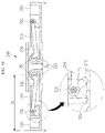
- FIG. 10 illustrates a cross-sectional view taken along line A-A of FIG. 3 showing an unfolded state of a hinge according to an exemplary embodiment of the present inventive concepts.
- FIG. 11 illustrates a cross-sectional view showing a 45-degree folded state of a hinge according to an exemplary embodiment of the present inventive concepts.
- FIG. 12 illustrates a cross-sectional view showing a 90-degree folded state of a hinge according to an exemplary embodiment of the present inventive concepts.
- FIG. 13 illustrates an exploded perspective view of a foldable plate according to an exemplary embodiment of the present inventive concepts.
- FIG. 14 illustrates an exploded perspective view of a folded region of a foldable plate according to an exemplary embodiment of the present inventive concepts.
- FIG. 15 illustrates a cross-sectional view showing a state in which a foldable plate covers a slide gap between a support plate and a hinge cover according to an exemplary embodiment of the present inventive concepts.
- FIG. 16 illustrates a perspective view of a support housing and an enlarged view of a side portion of the support housing according to an exemplary embodiment of the present inventive concepts.
- FIG. 17 illustrates a perspective view of a support housing and an enlarged view of a side portion of the support housing according to according to an exemplary embodiment of the present inventive concepts.
- FIG. 1A illustrates a perspective view of a foldable display device according to an exemplary embodiment of the present invention
- FIG. 1B illustrates a perspective view of a foldable display device that is folded according to an exemplary embodiment of the present invention.
- the display device 10 includes a first display area DA 1 , a second display area DA 2 , and a folded area FA.
- the folded area FA is disposed between the first display area DA 1 and the second display area DA 2 (e.g., in the first direction D 1 ).
- the folded area FA is an area where the foldable display device 10 is folded.
- the folded area FA may include at least one rotation axis for folding the display device 10 .
- the first display area DA 1 and the second display area DA 2 are areas where an image is displayed. An image is also displayed in the folded area FA. One image may be displayed on the first display area DA 1 , the second display area DA 2 , and the folded area FA. Alternatively, separate images may optionally be displayed in the first display area DA 1 , the second display area DA 2 , and/or the folded area FA.
- the foldable display device 10 may be folded by rotating the first display area DA 1 and the second display area DA 2 with respect to the folded area FA.
- the foldable display device 10 may be outwardly folded and a display surface of the first display area DA 1 and a display surface of the second display area DA 2 may face outward in the folded state of the foldable display device 10 .
- a display surface of the first display area DA 1 and a display surface of the second display area DA 2 may face outward in the folded state of the foldable display device 10 .
- a first direction D 1 indicates a direction perpendicular to the rotation axis of the foldable display device 10 .
- the first direction D 1 may extend along the longitudinal direction of the display surface, such as the relatively longer side of a rectangular foldable display device 10 .
- a second direction D 2 indicates a direction parallel to the rotation axis of the foldable display device 10 (referred to as a rotation axis direction) and may extend along the relatively shorter side of a rectangular foldable display device 10 .
- a third direction D 3 indicates a thickness direction of the foldable display device 10 .
- the display surface of the foldable display device 10 may be defined by the first direction D 1 and the second direction D 2 .
- FIG. 2 illustrates an exploded perspective view of a foldable display device according to an exemplary embodiment of the present inventive concepts.
- the foldable display device 10 may include a support housing 100 , a hinge 200 , a foldable plate 300 , and a display panel module 400 .
- the support housing 100 includes a support plate 110 , a hinge cover 120 , and a housing 130 .
- the hinge cover 120 is disposed at a center of the housing 130
- the support plate 110 is disposed at opposite sides of the hinge cover 120 .
- the hinge 200 may be configured to rotate the opposite ends of the support plate 110 about two rotational axes that are parallel to the second direction D 2 and are spaced apart in the first direction D 1 . A specific configuration of the hinge 200 will be described later. Portions of the hinge 200 extend inside the housing 130 , and the hinge cover 120 covers portions of the hinge 200 . The opposite ends of the hinge 200 (e.g., in the first direction D) may be connected to the support plates 110 on opposite sides of the hinge cover 120 , respectively.
- the foldable plate 300 may be affixed (e.g., adhered) to the support housing 100 .
- the foldable plate 300 may be affixed to the support plate 110 and the hinge cover 120 .
- a bottom surface of the foldable plate 300 e.g., in the third direction D 3
- a top surface e.g., in the third direction D 3
- the foldable plate 300 may form a flat surface by covering a step generated when the foldable display device 10 is unfolded.
- the foldable plate 300 may include a metal layer and an elastic layer.
- the display panel module 400 is affixed (e.g., adhered) to the foldable plate 300 .
- a bottom surface of the display panel module 400 e.g., in the third direction D 3
- a top surface e.g., in the third direction D 3
- the display panel module 400 may include a flexible display panel and various functional members.
- the functional members may include a touch panel, an optical member, a protective member, and the like.
- hinge 200 will be described in more detail with reference to FIG. 3 to FIG. 5B .
- FIG. 3 illustrates a perspective view of a hinge according to an exemplary embodiment of the present invention.
- FIG. 4 illustrates an exploded perspective view of a hinge according to an exemplary embodiment of the present invention.
- FIG. 5A illustrates a perspective view showing a portion of the hinge according to an exemplary embodiment of the present invention
- FIG. SB illustrates a side view showing a connection state between a first slider and a second slider according to an exemplary embodiment of the present invention.
- FIG. SB illustrates a side view of a portion indicated by a dotted line mark in FIG. 5A .
- the hinge 200 includes a first slider 210 , a second slider 220 , a rotation axis module 230 , a slider holder 240 , a link arm 250 , a link arm holder 260 , and a rotation axis cover 270 .
- the first slider 210 is disposed at both left and right sides (e.g., in the first direction D 1 ) of the rotation axis module 230 .
- the first slider 210 has a first body that extends longitudinally generally in a direction of the rotation axis (e.g., in the second direction D 2 ).
- opposite sides of the first body of the first slider 210 indicate opposite sides in the direction of the rotation axis.
- the first slider 210 includes a rotation axis connector 211 , a first sidewall 212 , a first guideline 213 , and a first slider holder connector 214 .
- the rotation axis connector 211 is formed to protrude from the opposite sides (e.g., in the second direction D 2 ) of the first body toward the rotation axis (e.g., in the first direction D 1 ) and be connected to the rotation axis module 230 .
- the first sidewall 212 is disposed at opposite sides of the first body and protrudes from the first body in the third direction D 3 .
- the first sidewall 212 may be disposed at lateral edges of the first body in the second direction D 2 and protrudes upwardly in the third direction D 3 .
- the first sidewall 212 may include a surface that is parallel to the first direction D 1 and the third direction D 3 .
- the first sidewall 212 includes a relatively planar top surface (e.g., in the third direction D 3 ) that extends in the first direction D 1 and the second direction D 2 .
- the first sidewall 212 may be a double wall structure connected to a bottom surface or an upper side surface of the first slider 210 .
- the first guide line 213 is disposed at the first sidewall 212 .
- the first guide line 213 may be a slit that extends through the first sidewall 212 .
- the first guide line 213 may be declined toward the rotation axis from an upper side to a lower side of the first sidewall 212 .
- the first guide line 213 may be formed in each of double walls of the first sidewall 212 in a same shape when the first sidewall 212 is viewed in the direction of the rotation axis (e.g., the second direction D 2 ).
- the first slider holder connector 214 includes a hole or an opening through which the slider holder 240 may be inserted.
- the first slider 210 may include a plurality of first slider holder connectors 214 .
- a second slider 220 is disposed at both left and right sides (e.g., in the first direction D 1 ) of the rotation axis module 230 .
- the support plate 110 may be connected to the second slider 220 and the support plate may move depending on an operation of the second slider 220 .
- the second slider 220 has a second body that extends longitudinally generally in the direction of the rotational axis (e.g., in the second direction D 2 ) and is configured to slide with the first slider 210 .
- the second slider 220 includes a second sidewall 222 , a second guide line 223 , and a second slider holder connector 224 .
- the second sidewall 222 is disposed at opposite sides of the second body to protrude from the second body in the third direction D 3 .
- the second sidewall 222 may be disposed at lateral edges of the second body in the second direction D 2 and protrudes upwardly in the third direction D 3 .
- the second sidewall 222 may include a surface that is parallel to the first direction D 1 and the third direction D 3 .
- the second sidewall 222 may be a double wall structure connected by another surface, such as a back wall, that is parallel to the second direction D 2 and the third direction D 3 .
- the second sidewall 222 may be coupled with the first sidewall 212 while being overlapped therewith.
- the double walls of the second sidewall 222 may be configured to receive the double walls of the first sidewall 212 therebetween.
- the second guide line 223 may be a slit that extends through the second sidewall 222 .
- the second guide line 223 may be formed to be inclined in a direction that is towards the rotation axis from a lower side (e.g., in the third direction D 3 ) to an upper side (e.g., in the third direction) of the second sidewall 222 .
- the second guide line 223 may be formed in each of double walls of the second sidewall 222 in a same shape when the second sidewall 222 is viewed in the direction of the rotation axis (e.g., in the second direction D 2 ).
- the first guide line 213 and the second guide line 223 are illustrated as linear slits in the exemplary embodiment shown in FIG. 4 , in other exemplary embodiments at least one of the first guide line 213 and the second guide line 223 may be a curved slit or may have a variety of different shapes and dimensions.
- the second slider holder connector 224 has at least one slit into which the slider holder 240 connected to the first slider may be inserted.
- the second slider holder connector 224 may be a pair of slits that are spaced apart on the second slider holder connector 224 in the second direction D 2 and may be adjacent to the second sidewalls 222 .
- the second slider holder connector 224 may extend in the first direction D 1 from the second body, and may overlap the first slider holder connector 214 .
- the second slider holder connector 224 may serve to guide the second slider 220 to slide in the first direction D 1 .
- the second slider 220 may include at least two second slider holder connectors 224 corresponding to the first slider holder connectors 214 .
- the rotation axis module 230 may include a first rotation axis module 230 a and a second rotation axis module 230 b that are seated on seating portions 271 at opposite sides (e.g., in the second direction D 2 ) of the rotation axis cover 270 .
- Each of the first rotation axis module 230 a and second rotation axis module 230 b includes two connection shafts 231 to which the first sliders 210 at left and right sides thereof are respectively connected.
- the two rotation axis connectors 211 of the first slider 210 at a left side are respectively connected to the connection shaft 231 at a left side of a first rotation axis module 230 a and the connection shaft 231 at a left side of a second rotation axis module 230 b .
- the two rotation axis connectors 211 of the first slider 210 at a right side are respectively connected to the connection shaft 231 at a right side of a first rotation axis module 230 a and the connection shaft 231 at a right side of a second rotation axis module 230 b .
- the first slider 210 and the second slider 220 rotate about the connection shaft 231 of the rotation axis module 230 .
- the rotation axis module 230 interlocks the first slider 210 at the left side and the first slider 210 at the right side to perform folding and unfolding.
- the rotation axis module 230 may enhance a sensation of the folding motion imparted to the user as the foldable display device 10 is folded. A structure of the rotation axis module 230 will be described later.
- the slider holder 240 When the second slider 220 overlaps the first slider 210 on the first slider, the slider holder 240 is coupled to the first slider holder connector 214 through the second slider holder connector 224 . Accordingly, the second slider 220 may slide on the first slider 210 along the second slider holder connector 224 in the first direction D 1 .
- the link arm holder 260 is coupled to end portions of the seating portions 271 at opposite sides (e.g., in the second direction D 2 ) of the rotation axis cover 270 .
- the link arm holder 260 includes two link shaft holders 266 corresponding to the two connection shafts 231 of the rotation axis module 230 .
- the link arm 250 includes a link arm body, a link arm pin 255 , and a link arm rotation axis 256 .
- the link arm body includes a portion extending toward the rotation axis, a hole portion which is configured to receive the link arm pin 255 at a first end (e.g., an end farthest from the link arm rotation axis 256 ) of the extended portion, and a portion bent in a direction of about 90 degrees (e.g., extending in the third direction D 3 ) from a second end (e.g., an end adjacent the link arm rotation axis) of the extended portion.
- the hole portion of the link arm body is positioned to overlap (e.g., in the second direction D 2 ) the first guide line 213 of the first slider 210 and the second guide line 223 of the second slider 220 .
- the link arm pin 255 is coupled to the hole portion of the link arm 250 and extends through the second guide line 223 and the first guide line 213 .
- the link arm rotation axis 256 protrudes in the second direction D 2 from the bent portion of the link arm body to be inserted into the link arm holder 260 attached to the seating portions 271 of the rotational axis cover 270 .
- the link arm 250 rotates about the link arm rotation axis 256 .
- Two link arms 250 a , 250 b may be coupled to the first and second sliders 210 and 220 at the left side, and another two link arms may be coupled to the first and second sliders 210 and 220 at the right side.
- the link arm pin 255 is fixed to the link arm 250 through the second guide line 223 and the first guide line 213 . Since the link arm 250 rotates about the link arm rotation axis 256 , the link arm pin 255 may move along the first guide line 213 in a diagonal downward direction and the second slider 220 may move in a direction toward the first slider 210 as the foldable display device 10 is folded. When the foldable display device 10 is unfolded, the link arm pin 255 may move along the first guide line 213 in a diagonal upward direction, and the second slider 220 may move in a direction away from the first slider 210 . A sliding distance Sd of the second slider 220 is determined depending on an inclination of the first guide line 213 and the second guide line 223 in a diagonal direction.
- FIG. 6 illustrates an exploded perspective view of a rotation axis module according to an exemplary embodiment of the present inventive concepts.
- FIG. 7A illustrates a perspective view of a rotation axis module according to an exemplary embodiment of the present inventive concepts.
- FIG. 7B illustrates a perspective view of a cam of a rotation axis module according to an exemplary embodiment of the present inventive concepts.
- FIG. 7C illustrates a perspective view showing a connection portion between a rotation axis module and a first slider according to an exemplary embodiment of present inventive concepts.
- FIG. 8 illustrates a cross-sectional view showing a connection state between a main gear and a pinion gear according to an exemplary embodiment of the present inventive concepts.
- FIG. 7A illustrates a perspective view of a rotation axis module according to an exemplary embodiment of the present inventive concepts.
- FIG. 7B illustrates a perspective view of a cam of a rotation axis module according to an exemplary embodiment of the present inventive concepts.
- FIG. 9A illustrates a perspective view of a rotation axis module according to another exemplary embodiment of the present inventive concepts.
- FIG. 9B illustrates a perspective view of a cam of a rotation axis module according to another exemplary embodiment of the present inventive concepts.
- FIG. 9C illustrates a perspective view showing a connection state between a rotation axis module and a first slider according to another exemplary embodiment of the present inventive concepts.
- FIG. 9D illustrates a perspective view showing a connection portion between a rotation axis module and a first slider according to another exemplary embodiment of present inventive concepts.
- FIG. 9D illustrates a display portion of FIG. 9C indicated by a dotted line.
- the rotation axis module 230 includes a shaft and gear, a pinion gear 234 , a cam module, a spring 237 , a module housing 238 , and a gear cover 239 .
- the shaft and gear includes a connection shaft 231 , a main gear 232 , and a shaft 233 .
- the connection shaft 231 and the shaft 233 form a single rotation axis.
- the main gear 232 is disposed between the connection shaft 231 and the shaft 233 (e.g., in the second direction D 2 ), and the connection shaft 231 and the shaft 233 serve as a rotation axis of the main gear 232 .
- the rotation axis module 230 includes a pair of shafts and gears (e.g., arranged in the first direction D 1 ), and the pair of shafts and gears serve as two rotation axes of the foldable display device 10 (e.g., a left rotation axis and a right rotation axis in the first direction D 1 ).
- two pinion gears 234 are engaged between two main gears 232 so that the two main gears 232 rotate together.
- the two main gears 232 that are connected by the two pinion gears 234 rotate in opposite directions.
- the cam module includes two rotary cams 235 and one fixed cam 236 .
- the rotary cams 235 are spaced apart in the first direction D 1 and include an engagement hole to be engaged with the shaft 233 , and are configured to rotate together with the shaft 233 .
- the fixed cam 236 includes two cam portions arranged in the first direction D 1 that engage the two rotary cams 235 .
- the fixed cam 236 may include two through-holes for penetrating the two shafts 233 without engaging the shaft.
- the rotary cams 235 or the fixed cam 236 may include a plurality of protrusions 235 - 1 protruding from an edge thereof in a direction of the rotation axis (e.g., in the second direction D 2 ) about the rotation axis, and a plurality of recesses 235 - 2 between the protrusions 235 - 1 .
- the rotary cams 235 or the fixed cam 236 may include three protrusions 235 - 1 and three recesses 235 - 2 .
- Each of the protrusions 235 - 1 is formed as a slip surface having a flat distal end, and the slip surface contacts a surface of the corresponding recess 235 - 2 as an inclined surface.
- an edge length of the slip surface of the protrusion 235 - 1 may be approximately 0.9 mm, and an inclination angle Dg of the inclined surface may be approximately 110 degrees.
- the edge length of the slip surface of the protrusion 235 - 1 may be between 0.6 mm-1.2 mm and the inclined surface may be approximately 95-125 degrees.
- the edge length of the slip surface and a magnitude of the inclination angle Dg are not limited to these exemplary embodiments.
- Two springs 237 may support the fixed cam 236 .
- two springs 237 are configured to exert a biasing force in the second direction D 2 to support the fixed cam 236 .
- the two shafts 233 extending through the fixed cam 236 may be respectively disposed at centers of the coil-shaped springs 237 .
- the springs 237 provide a biasing force or “connection force” against the fixed cam 236 to connect the fixed cam 236 to the rotary cams 235 .
- the number of springs and the configuration of the springs may be modified.
- the rotary cams 235 and the fixed cam 236 are subjected to normal engagement and open engagement. Therefore, the rotary cams 235 and fixed cam 236 help impart a sensation of the folding motion of the foldable display device 10 to the user during a folding operation of the foldable display device 10 .
- the normal engagement of the cam module indicates a state in which the rotary cams 235 are engaged with the fixed cam 236 by allowing the protrusions 235 - 1 to be inserted into the recesses 235 - 2 of the counterpart.
- the open engagement of the cam module indicates a state in which the protrusions 235 - 1 of the rotary cams 235 and the fixed cam 236 face each other such that a space is formed between the recesses 235 - 2 .
- the cam module may be in a normal engagement state when the foldable display device 10 is in a fully folded state, and may be in an open engagement state when it is in a middle state between the fully folded state and the unfolded state.
- the module housing 238 includes a body portion, a first support wall 238 - 1 , and a second support wall 238 - 2 spaced apart in the second direction D 2 .
- the first support wall 238 - 1 protrudes from a first side of the body portion in the third direction D 3 .
- the first support wall 238 - 1 includes two through holes 238 - 12 through which the two shafts 233 extend.
- the second support wall 238 - 2 protrudes from a second side of the body portion in the third direction D 3 to face the first support wall 238 - 1 .
- the two rotation cams 235 , the fixed cam 236 , and the two springs 237 are disposed between the first support wall 238 - 1 and the second support wall 238 - 2 .
- the shaft 233 may extend through the through hole 238 - 12 of the module housing 238 , the engagement hole of the rotary cam 235 , the through hole of the fixed cam 236 , and the center of the spring 237 to be supported by the second support wall 238 - 2 .
- a gear cover 239 includes a body portion and a stopper 239 - 1 .
- the body portion may have a surface shape that extends in the first direction D 1 and the third direction D 3 .
- the body portion of the gear cover 239 may include two through holes that penetrate the two connection shafts 231 .
- the stopper 239 - 1 may include two stoppers 239 - 1 , which protrude in the second direction D 2 from edges of each of the two through holes of the body portion.
- the rotation axis connectors 211 of the first slider 210 are connected to the connection shafts 231 .
- the rotation axis connector 211 has a groove shape which engages with the stopper 239 - 1 when the first slider 210 is in an unfolded state.
- stopper 239 - 1 is configured to prevent the first slider 210 from rotating beyond the unfolded state.
- a rotation axis module 230 ′ may further include a third spring 237 ′ to increase the connection force of the cam module.
- the shaft 233 may extend further through the second support wall 238 - 2 of the module housing 238 .
- the positions of the cam module and the springs 237 and 237 ′ may be opposite to those of the cam module and the spring of FIG. 7A .
- the cam module includes a rotary cam 235 ′ and a fixed cam 236 ′. Positions of the rotary cam 235 ′ and the fixed cam 236 ′ may also be opposite to those of the rotary cam 235 and the fixed cam 236 of FIG. 7A .
- the springs may be positioned adjacent the main gear 232 and the pinion gears 234 in the second direction D 2 and the rotary cams 235 ′ may be adjacent the second support wall 238 - 2 .
- one of the rotation cam 235 ′ and the fixed cam 236 ′ has two protrusions 235 ′- 1 and recesses 235 - 2 ′ between the two protrusions 235 ′- 1 .
- the edge length of the slip surface of each of the protrusions 235 ′- 1 is approximately 1.2 mm, and the inclination angle Dg′ of the inclined surface may be approximately 120 degrees.
- the edge length of the slip surface of the protrusion 235 ′- 1 may be between 0.8 mm-1.6 mm and the inclined surface may be approximately 105-135 degrees.
- the edge length of the slip surface and a magnitude of the inclination angle Dg′ are not limited.
- an additional rotation axis connector 211 ′ may be connected to the shaft 233 that further extends through the second support wall 238 - 2 , and a shaft cover 239 ′ may be connected to an end portion of the shaft 233 .
- the additional rotation axis connector 211 ′ connects the first body of the first slider 210 to the shaft 233 .
- the shaft cover 239 ′ includes a body portion and a stopper 239 ′- 1 .
- the body portion may have a top surface that extends in the first direction D 1 and the second direction D 2 , and may have holes into which the two shafts 233 are inserted (e.g., in the third direction D 3 ).
- the stopper 239 ′- 1 may include two stoppers 239 ′- 1 , which protrude in the second direction D 2 from edges of each of the two holes of the body portion.
- the additional rotation axis connector 211 ′ has a groove shape to engage with the stopper 239 - 1 when the first slider 210 is in the unfolded state.
- FIG. 10 illustrates a cross-sectional view showing an unfolded state of a hinge taken along line A-A′ of FIG. 3 according to an exemplary embodiment of the present inventive concepts.
- FIG. 11 illustrates a cross-sectional view showing a 45-degree folded state of a hinge according to an exemplary embodiment of the present inventive concepts.
- FIG. 12 illustrates a cross-sectional view showing a 90-degree folded state of a hinge according to an exemplary embodiment of the present inventive concepts.
- FIG. 10 to FIG. 12 the operation of the hinge 200 will be described by taking a cross-sectional view taken along line A-A′ of FIG. 3 as an example.
- the link arm rotation axis 256 is disposed at a bent portion of the link arm 250 , and rotation axes Xb of the link arm 250 are not aligned with rotation axes Xa of the sliders 210 and 220 .
- the link arm rotation axes Xb of the link arm 250 may protrude at the bent portion of the link arm away from rotation axes Xa of the sliders 210 and 220 .
- the sliders 210 and 220 rotate about the rotation axes Xa and the link arm 250 rotates about the rotation axis Xb of the link arm 250 .
- the link arm pin 255 is positioned at upper ends (e.g., in the third direction D 3 ) of the first guide line 213 and the second guide line 223 .
- the link arm pin 255 moves along the first guideline 213 of the first slider 210 . Further, the link arm pin 255 moves along the second guide line 223 of the second slider 220 . Accordingly, when the hinge 200 is in a 45-degree folding state, the link arm pin 255 is positioned at a middle portion of the first guide line 213 and at a middle portion of the second guide line 223 . As a result, the second slider 220 moves in a direction toward the first slider 210 .
- a first distance La between the rotation axis Xa when the hinge 200 is in the unfolded state and an outermost part of the second slider 220 is larger than a second distance Lb between the rotation axis Xa when the hinge 200 is in the 45-degree folded state and the outermost part of the second slider 220 .
- FIG. 11 and FIG. 12 illustrate only one of the sliders 210 and 220 folded for comparison with the unfolded state.
- the foldable display device 10 may permit only one of the sliders 210 and 220 to be folded.
- the link arm pin 255 is positioned at lower ends of the first guide line 213 and the second guide line 223 .
- the lower ends of the first guide line 213 and the second guide line 223 are in relation to the third direction D 3 when the foldable device 10 is in an unfolded state.
- the second slider 220 maximally moves in a direction toward the first slider 210 .
- the second distance Lb between the rotation axis Xa when the hinge 200 is in the 45-degree folded state and the outermost part of the second slider 220 is larger than a third distance Lc between the rotation axis Xa when the hinge 200 is in the 90-degree folded state and the outermost part of the second slider 220 .
- FIG. 13 illustrates an exploded perspective view of a foldable plate according to an exemplary embodiment of the present inventive concepts.
- FIG. 14 illustrates an exploded perspective view of a folded region of a foldable plate according to an exemplary embodiment of the present invention.
- FIG. 15 illustrates a cross-sectional view showing a state in which a foldable plate covers a slide gap between a support plate and a hinge cover.
- the foldable plate 300 may include a metal plate 310 , an elastic plate 320 , and an adhesive layer 330 .
- the elastic plate 320 is disposed on the metal plate 310 .
- a bottom portion of the elastic plate 320 e.g., in the third direction D 3
- the adhesive layer 330 is disposed below the metal plate 310 (e.g., in the third direction D 3 ).
- the display panel module 400 is disposed on the elastic plate 320 .
- the display panel module 400 may be affixed (e.g., adhered) to the elastic plate 320 .
- the metal plate 310 includes a pattern portion 311 , a first support portion 312 , and a second support portion 313 .
- the pattern portion 311 corresponds to a portion forming a curved surface when the foldable display device 10 is folded.
- the first support portion 312 may correspond to the support plates 110 at opposite sides of the support housing 100 , and may be adhered to the support plate 110 by the adhesive layer 330 .
- the second support portion 313 may correspond to a portion between the two rotation axes of the hinge 200 , and may be adhered to the hinge cover 120 by the adhesive layer 330 .
- One pattern portion 311 is disposed between the first support portion 312 and the second support portion 313 at the left side (e.g., in the first direction D 1 ), and another pattern portion 311 is disposed between the first support portion 312 and the second support portion 313 at the right side (e.g., in the first direction).
- the pattern portion 311 includes bar-shaped patterns extending in the second direction D 2 .
- the bar-shaped pattern portion 311 may be formed by removing a portion of the metal plate 310 by a mechanical or chemical method at a portion corresponding to the pattern portion 311 in the metal plate 310 .
- a plurality of grooves GV that are mechanically or chemically removed from the metal plate 310 are formed between the bar-shaped patterns.
- the pattern portion 311 may provide flexibility for the foldable plate 300 by the grooves GV extending in the second direction D 2 .
- the metal plate 310 may include stainless steel. However, exemplary embodiments of the present inventive concepts are not limited thereto and the metal plate 310 may include various metals or alloys.
- the elastic plate 320 is disposed between the metal plate 310 and the display panel module 400 .
- the elastic plate 320 may cover a step generated depending on sliding motion of the sliders 210 and 220 , and may provide a flat surface to the display panel module 400 .
- the elastic plate 320 may include a thermoplastic polyurethane resin.
- exemplary embodiments of the present inventive concepts are not limited thereto and the elastic plate 320 may include various other elastic materials.
- a slide gap SG exists between the support plate 110 and the hinge cover 120 as the support plate 110 is connected to the second slider 220 and moves together with the second slider 220 .
- the slide gap SG provides a moving space through which the support plate 110 may slide.
- the slide gap SG is minimized in the folded state, and is maximized in the unfolded state.
- a step is generated by the slide gap SG.
- the foldable plate 300 is configured to cover the step. Since the foldable plate 300 supports the display panel module 400 on the step as a flat surface, the display panel module 400 is not affected by the step.
- FIG. 16 illustrates a perspective view of a support housing and an enlarged view of a side portion of the support housing according to an exemplary embodiment of the present invention.
- FIG. 17 illustrates a perspective view of a support housing and an enlarged view of a side portion of the support housing according to another exemplary embodiment of the present invention.
- the support housing 100 may be formed such that a side surface thereof connecting an upper surface and a lower surface is vertically formed (e.g., extending in the third direction D 3 ).
- a first side surface 100 - 1 and a second side surface 100 - 2 connecting the upper and lower surfaces of the support housing 100 may include curved surfaces.
- the first side surface 100 - 1 may be a side surface that is parallel to the rotation axis (e.g., extends in the second direction D 2 ), and the second side surface 100 - 2 may be a side surface that is perpendicular to the rotation axis (e.g., extends in the first direction D 1 ).
- the first side surface 100 - 1 may include a curved surface facing the side surface at the upper surface (e.g., in the third direction D 3 ), a curved surface facing the side surface at the lower surface (e.g., in the third direction D 3 ), and the side surface vertically connecting ends of the two curved surfaces and extending in the third direction D 3 .
- the second side surface 100 - 2 may include a curved side surface that convexly connects the end of the upper surface and the end of the lower surface.
Abstract
Description
Claims (21)
Applications Claiming Priority (2)
| Application Number | Priority Date | Filing Date | Title |
|---|---|---|---|
| KR1020190060773A KR20200135636A (en) | 2019-05-23 | 2019-05-23 | Foldable display device |
| KR10-2019-0060773 | 2019-05-23 |
Publications (2)
| Publication Number | Publication Date |
|---|---|
| US20200375046A1 US20200375046A1 (en) | 2020-11-26 |
| US11516932B2 true US11516932B2 (en) | 2022-11-29 |
Family
ID=73442288
Family Applications (1)
| Application Number | Title | Priority Date | Filing Date |
|---|---|---|---|
| US16/879,993 Active 2040-08-26 US11516932B2 (en) | 2019-05-23 | 2020-05-21 | Foldable display device |
Country Status (4)
| Country | Link |
|---|---|
| US (1) | US11516932B2 (en) |
| KR (1) | KR20200135636A (en) |
| CN (1) | CN111986568A (en) |
| TW (1) | TW202105341A (en) |
Cited By (5)
| Publication number | Priority date | Publication date | Assignee | Title |
|---|---|---|---|---|
| US20210405711A1 (en) * | 2020-06-30 | 2021-12-30 | Dell Products L.P. | Information handling system variable torque hinge |
| US20220321683A1 (en) * | 2019-12-20 | 2022-10-06 | Huawei Technologies Co., Ltd. | Foldable screen device |
| US20220346258A1 (en) * | 2021-04-25 | 2022-10-27 | Beijing Xiaomi Mobile Software Co., Ltd. | Coupling assembly and display terminal |
| US11681335B1 (en) * | 2022-02-21 | 2023-06-20 | Fositek Corporation | Hinge for a flexible electronic device |
| US11940839B2 (en) | 2021-03-31 | 2024-03-26 | Samsung Electronics Co., Ltd. | Hinge structure including compound gear and foldable electronic device including the same |
Families Citing this family (26)
| Publication number | Priority date | Publication date | Assignee | Title |
|---|---|---|---|---|
| USD934855S1 (en) * | 2019-05-06 | 2021-11-02 | Dell Products L.P. | Portable information handling system |
| US10955880B2 (en) * | 2019-06-28 | 2021-03-23 | Apple Inc. | Folding electronic devices with geared hinges |
| KR20210047389A (en) * | 2019-10-21 | 2021-04-30 | 삼성디스플레이 주식회사 | Display device |
| CN110767091B (en) * | 2019-10-31 | 2021-08-17 | 云谷(固安)科技有限公司 | Folding display device |
| USD957389S1 (en) * | 2019-12-03 | 2022-07-12 | Samsung Electronics Co., Ltd. | Electronic device |
| KR20210086853A (en) * | 2019-12-31 | 2021-07-09 | 삼성디스플레이 주식회사 | Display apparatus |
| KR20210115633A (en) * | 2020-03-15 | 2021-09-27 | (주)에이유플렉스 | Hinge Structure for Infolding type Display Device |
| KR20220006671A (en) * | 2020-07-08 | 2022-01-18 | 삼성디스플레이 주식회사 | Electronic device |
| US11615720B2 (en) * | 2020-08-26 | 2023-03-28 | Samsung Display Co., Ltd. | Display device |
| JP2022085726A (en) * | 2020-11-27 | 2022-06-08 | 株式会社ナチュラレーザ・ワン | Hinge and office machine using this hinge |
| KR20230091123A (en) * | 2020-12-21 | 2023-06-22 | 엘지전자 주식회사 | mobile terminal |
| EP4175265A4 (en) | 2020-12-28 | 2024-01-24 | Samsung Electronics Co Ltd | Hinge structure and foldable electronic device comprising same |
| JP7369217B2 (en) | 2021-01-29 | 2023-10-25 | サムスン エレクトロニクス カンパニー リミテッド | Hinge structures and electronic devices including hinge structures |
| US11385687B1 (en) | 2021-01-29 | 2022-07-12 | Samsung Electronics Co., Ltd. | Hinge structure and electronic device including the same |
| KR20220109722A (en) * | 2021-01-29 | 2022-08-05 | 삼성전자주식회사 | Hinge structure and electronic device including the same |
| JP2024511715A (en) * | 2021-03-01 | 2024-03-15 | リュー、サン キュ | flexible display portable equipment |
| TWI788844B (en) * | 2021-05-13 | 2023-01-01 | 達運精密工業股份有限公司 | Foldable metal back panel |
| CN115643323A (en) * | 2021-07-20 | 2023-01-24 | 深圳市富世达通讯有限公司 | Folding screen device |
| CN113487972B (en) * | 2021-07-22 | 2023-01-20 | 京东方科技集团股份有限公司 | Foldable module and display device |
| CN115076218B (en) * | 2021-08-03 | 2023-04-07 | 华为技术有限公司 | Electronic device and folding device |
| KR20230044644A (en) * | 2021-09-27 | 2023-04-04 | 삼성전자주식회사 | Hinge assembly and electronic device comprising the same |
| CN116368550A (en) * | 2021-09-27 | 2023-06-30 | 京东方科技集团股份有限公司 | Pivotable support device and display device |
| CN114017436B (en) * | 2021-10-26 | 2023-06-27 | 武汉华星光电技术有限公司 | Hinge, flexible display panel and electronic device |
| CN116085378A (en) * | 2021-11-08 | 2023-05-09 | Oppo广东移动通信有限公司 | Folding device and electronic equipment |
| CN114078390B (en) * | 2021-11-15 | 2023-02-28 | 武汉华星光电半导体显示技术有限公司 | Folding display device |
| WO2023163352A1 (en) * | 2022-02-22 | 2023-08-31 | 삼성전자주식회사 | Electronic device comprising foldable display |
Citations (32)
| Publication number | Priority date | Publication date | Assignee | Title |
|---|---|---|---|---|
| US20110289728A1 (en) * | 2010-05-27 | 2011-12-01 | Hon Hai Precision Industry Co., Ltd. | Hinge mechanism |
| US20120042473A1 (en) * | 2010-08-18 | 2012-02-23 | Hon Hai Precision Industry Co., Ltd. | Hinge mechanism |
| US20120096678A1 (en) * | 2010-10-26 | 2012-04-26 | Hon Hai Precision Industry Co., Ltd. | Hinge mechanism |
| KR20140091273A (en) | 2013-01-11 | 2014-07-21 | (주) 프렉코 | Foldable flexible display device |
| KR20140091272A (en) | 2013-01-11 | 2014-07-21 | (주) 프렉코 | Foldable flexible display device |
| KR20140091274A (en) | 2013-01-11 | 2014-07-21 | (주) 프렉코 | Foldable flexible display device |
| US8938855B2 (en) * | 2011-12-14 | 2015-01-27 | Samsung Electronics Co., Ltd. | Gear hinge device for portable apparatus |
| KR20160087972A (en) | 2015-01-14 | 2016-07-25 | 삼성디스플레이 주식회사 | Folderable display device |
| KR20170003801A (en) | 2015-06-30 | 2017-01-10 | 삼성디스플레이 주식회사 | Foldable display apparatus |
| US9677308B1 (en) * | 2016-08-18 | 2017-06-13 | Lianhong Art Co., Ltd. | Hinge having movable shaft |
| KR20170087000A (en) | 2016-01-19 | 2017-07-27 | 박현민 | Hinge Structure for Mobile Device with Flexible Display installed |
| US9848502B1 (en) * | 2017-03-24 | 2017-12-19 | Shin Zu Shing Co., Ltd. | Hinge assembly and foldable display device using the same |
| KR20180029590A (en) | 2016-09-13 | 2018-03-21 | 삼성전자주식회사 | Flexible Display Electronic device |
| KR20180036903A (en) | 2016-09-30 | 2018-04-10 | 엘지디스플레이 주식회사 | Foldable display device |
| KR20180052059A (en) | 2016-11-07 | 2018-05-17 | 박현민 | Hinge Structure for Folderable Display Device with Semi Automatic Pushing Module |
| US10036188B1 (en) * | 2017-06-08 | 2018-07-31 | First Dome Corporation | Hinge and a foldable electronic device with the same |
| KR20180098504A (en) | 2018-08-24 | 2018-09-04 | 삼성디스플레이 주식회사 | Case assembly for foldable display apparatus and foldable display apparatus |
| US10520988B2 (en) * | 2017-10-13 | 2019-12-31 | Fositek Corporation | Bendable display apparatus and supporting device |
| US20200063476A1 (en) * | 2018-08-21 | 2020-02-27 | Compal Electronics, Inc. | Synchronous hinge module |
| US20200267856A1 (en) * | 2019-02-16 | 2020-08-20 | Jarllytec Co., Ltd. | Hinge module for foldable type device |
| US10761573B2 (en) * | 2018-09-27 | 2020-09-01 | Jarllytec Co., Ltd. | Hinge module for a foldable type device |
| US10761574B1 (en) * | 2019-07-09 | 2020-09-01 | Fositek Corporation | Hinge mechanism and flexible electronic device having the same |
| US20200293094A1 (en) * | 2017-12-06 | 2020-09-17 | Hangzhou Amphenol Phoenix Telecom Parts Co., Ltd. | Hinge for mobile terminal having an inwardly bendable flexible screen and mobile terminal having an inwardly bendable flexible screen |
| US10824197B1 (en) * | 2019-09-19 | 2020-11-03 | First Dome Corporation | Folding shaft structure of flexible display screen |
| US10845850B1 (en) * | 2019-04-30 | 2020-11-24 | Samsung Electronics Co., Ltd. | Hinge structure and electronic device including the same |
| US20210165466A1 (en) * | 2019-12-02 | 2021-06-03 | Samsung Electronics Co., Ltd. | Foldable electronic device including hinge assembly |
| US20210271294A1 (en) * | 2019-03-15 | 2021-09-02 | Huawei Technologies Co., Ltd. | Rotating Shaft Mechanism and Mobile Terminal |
| US20210373612A1 (en) * | 2020-05-27 | 2021-12-02 | Samsung Electronics Co., Ltd. | Arm structure, hinge structure including the arm structure, and electronic device including the same |
| US11194365B2 (en) * | 2018-09-06 | 2021-12-07 | Compal Electronics, Inc. | Hinge module and electronic device |
| US20210396056A1 (en) * | 2020-06-18 | 2021-12-23 | Leohab Enterprise Co., Ltd. | Pivot Device Having Components Translatable During Rotation |
| US20210396455A1 (en) * | 2020-06-17 | 2021-12-23 | Lg Electronics Inc. | Refrigerator |
| US20210405711A1 (en) * | 2020-06-30 | 2021-12-30 | Dell Products L.P. | Information handling system variable torque hinge |
Family Cites Families (6)
| Publication number | Priority date | Publication date | Assignee | Title |
|---|---|---|---|---|
| KR102210047B1 (en) * | 2014-03-05 | 2021-02-01 | 엘지디스플레이 주식회사 | Foldable display apparatus |
| KR102244807B1 (en) * | 2014-03-07 | 2021-04-26 | 엘지디스플레이 주식회사 | Foldable display apparatus |
| KR102333557B1 (en) * | 2014-12-30 | 2021-12-01 | 엘지디스플레이 주식회사 | Foldable display apparatus |
| KR101814067B1 (en) * | 2015-11-06 | 2018-01-02 | (주) 프렉코 | Foldable Display Device |
| CN206282175U (en) * | 2016-08-25 | 2017-06-27 | 京东方科技集团股份有限公司 | Collapsible display device and display device |
| KR102392468B1 (en) * | 2017-06-30 | 2022-04-28 | 엘지디스플레이 주식회사 | Foldable display device |
-
2019
- 2019-05-23 KR KR1020190060773A patent/KR20200135636A/en not_active Application Discontinuation
-
2020
- 2020-05-20 CN CN202010428753.8A patent/CN111986568A/en active Pending
- 2020-05-21 US US16/879,993 patent/US11516932B2/en active Active
- 2020-05-22 TW TW109117097A patent/TW202105341A/en unknown
Patent Citations (33)
| Publication number | Priority date | Publication date | Assignee | Title |
|---|---|---|---|---|
| US20110289728A1 (en) * | 2010-05-27 | 2011-12-01 | Hon Hai Precision Industry Co., Ltd. | Hinge mechanism |
| US20120042473A1 (en) * | 2010-08-18 | 2012-02-23 | Hon Hai Precision Industry Co., Ltd. | Hinge mechanism |
| US20120096678A1 (en) * | 2010-10-26 | 2012-04-26 | Hon Hai Precision Industry Co., Ltd. | Hinge mechanism |
| US8938855B2 (en) * | 2011-12-14 | 2015-01-27 | Samsung Electronics Co., Ltd. | Gear hinge device for portable apparatus |
| KR20140091273A (en) | 2013-01-11 | 2014-07-21 | (주) 프렉코 | Foldable flexible display device |
| KR20140091272A (en) | 2013-01-11 | 2014-07-21 | (주) 프렉코 | Foldable flexible display device |
| KR20140091274A (en) | 2013-01-11 | 2014-07-21 | (주) 프렉코 | Foldable flexible display device |
| KR20160087972A (en) | 2015-01-14 | 2016-07-25 | 삼성디스플레이 주식회사 | Folderable display device |
| KR20170003801A (en) | 2015-06-30 | 2017-01-10 | 삼성디스플레이 주식회사 | Foldable display apparatus |
| KR20170087000A (en) | 2016-01-19 | 2017-07-27 | 박현민 | Hinge Structure for Mobile Device with Flexible Display installed |
| KR20170087008A (en) | 2016-01-19 | 2017-07-27 | 박현민 | Hinge Structure for Mobile Device with Flexible Display installed |
| US9677308B1 (en) * | 2016-08-18 | 2017-06-13 | Lianhong Art Co., Ltd. | Hinge having movable shaft |
| KR20180029590A (en) | 2016-09-13 | 2018-03-21 | 삼성전자주식회사 | Flexible Display Electronic device |
| KR20180036903A (en) | 2016-09-30 | 2018-04-10 | 엘지디스플레이 주식회사 | Foldable display device |
| KR20180052059A (en) | 2016-11-07 | 2018-05-17 | 박현민 | Hinge Structure for Folderable Display Device with Semi Automatic Pushing Module |
| US9848502B1 (en) * | 2017-03-24 | 2017-12-19 | Shin Zu Shing Co., Ltd. | Hinge assembly and foldable display device using the same |
| US10036188B1 (en) * | 2017-06-08 | 2018-07-31 | First Dome Corporation | Hinge and a foldable electronic device with the same |
| US10520988B2 (en) * | 2017-10-13 | 2019-12-31 | Fositek Corporation | Bendable display apparatus and supporting device |
| US20200293094A1 (en) * | 2017-12-06 | 2020-09-17 | Hangzhou Amphenol Phoenix Telecom Parts Co., Ltd. | Hinge for mobile terminal having an inwardly bendable flexible screen and mobile terminal having an inwardly bendable flexible screen |
| US20200063476A1 (en) * | 2018-08-21 | 2020-02-27 | Compal Electronics, Inc. | Synchronous hinge module |
| KR20180098504A (en) | 2018-08-24 | 2018-09-04 | 삼성디스플레이 주식회사 | Case assembly for foldable display apparatus and foldable display apparatus |
| US11194365B2 (en) * | 2018-09-06 | 2021-12-07 | Compal Electronics, Inc. | Hinge module and electronic device |
| US10761573B2 (en) * | 2018-09-27 | 2020-09-01 | Jarllytec Co., Ltd. | Hinge module for a foldable type device |
| US20200267856A1 (en) * | 2019-02-16 | 2020-08-20 | Jarllytec Co., Ltd. | Hinge module for foldable type device |
| US20210271294A1 (en) * | 2019-03-15 | 2021-09-02 | Huawei Technologies Co., Ltd. | Rotating Shaft Mechanism and Mobile Terminal |
| US10845850B1 (en) * | 2019-04-30 | 2020-11-24 | Samsung Electronics Co., Ltd. | Hinge structure and electronic device including the same |
| US10761574B1 (en) * | 2019-07-09 | 2020-09-01 | Fositek Corporation | Hinge mechanism and flexible electronic device having the same |
| US10824197B1 (en) * | 2019-09-19 | 2020-11-03 | First Dome Corporation | Folding shaft structure of flexible display screen |
| US20210165466A1 (en) * | 2019-12-02 | 2021-06-03 | Samsung Electronics Co., Ltd. | Foldable electronic device including hinge assembly |
| US20210373612A1 (en) * | 2020-05-27 | 2021-12-02 | Samsung Electronics Co., Ltd. | Arm structure, hinge structure including the arm structure, and electronic device including the same |
| US20210396455A1 (en) * | 2020-06-17 | 2021-12-23 | Lg Electronics Inc. | Refrigerator |
| US20210396056A1 (en) * | 2020-06-18 | 2021-12-23 | Leohab Enterprise Co., Ltd. | Pivot Device Having Components Translatable During Rotation |
| US20210405711A1 (en) * | 2020-06-30 | 2021-12-30 | Dell Products L.P. | Information handling system variable torque hinge |
Cited By (7)
| Publication number | Priority date | Publication date | Assignee | Title |
|---|---|---|---|---|
| US20220321683A1 (en) * | 2019-12-20 | 2022-10-06 | Huawei Technologies Co., Ltd. | Foldable screen device |
| US20210405711A1 (en) * | 2020-06-30 | 2021-12-30 | Dell Products L.P. | Information handling system variable torque hinge |
| US11662779B2 (en) * | 2020-06-30 | 2023-05-30 | Dell Products L.P. | Information handling system variable torque hinge |
| US11940839B2 (en) | 2021-03-31 | 2024-03-26 | Samsung Electronics Co., Ltd. | Hinge structure including compound gear and foldable electronic device including the same |
| US20220346258A1 (en) * | 2021-04-25 | 2022-10-27 | Beijing Xiaomi Mobile Software Co., Ltd. | Coupling assembly and display terminal |
| US11812569B2 (en) * | 2021-04-25 | 2023-11-07 | Beijing Xiaomi Mobile Software Co., Ltd. | Coupling assembly and display terminal |
| US11681335B1 (en) * | 2022-02-21 | 2023-06-20 | Fositek Corporation | Hinge for a flexible electronic device |
Also Published As
| Publication number | Publication date |
|---|---|
| US20200375046A1 (en) | 2020-11-26 |
| CN111986568A (en) | 2020-11-24 |
| TW202105341A (en) | 2021-02-01 |
| KR20200135636A (en) | 2020-12-03 |
Similar Documents
| Publication | Publication Date | Title |
|---|---|---|
| US11516932B2 (en) | Foldable display device | |
| CN109658826B (en) | Flexible screen and electronic equipment | |
| US10185367B2 (en) | Display device | |
| CN114779889B (en) | Hinge module and foldable electronic device including the same | |
| US20200257335A1 (en) | Folding member and display device including the same | |
| KR101013245B1 (en) | Hinge mechanism of foldable device and foldable device having the hinge mechanism | |
| JP2023521480A (en) | Folding devices and electronic devices | |
| KR20160027625A (en) | Foldable display apparatus | |
| JP4212577B2 (en) | Folding device hinge mechanism and folding device provided with this hinge mechanism | |
| EP3894984B1 (en) | Hinge module including detent structure and foldable electronic device including the hinge module | |
| EP2581613A1 (en) | Hinge device | |
| US11693455B2 (en) | Foldable hinge module for portable terminal | |
| KR20200101251A (en) | Structure of Hinge including a detent structure and Foldable Electronic Device including the same | |
| CN114697416A (en) | Folding mechanism and electronic equipment | |
| EP4300927A1 (en) | Hinge device comprising cam structure and electronic device comprising hinge device | |
| US20230217616A1 (en) | Foldable display apparatus | |
| CN109658827B (en) | Electronic device | |
| KR20190065930A (en) | Display apparatus | |
| US20230007797A1 (en) | Hinge, flexible display panel, and electronic device | |
| CN115691317A (en) | Foldable display device | |
| CN116389623A (en) | Foldable display device | |
| CN110767087A (en) | Foldable display device | |
| CN107882862B (en) | Hinge device and display device using the same | |
| KR102298726B1 (en) | Folding hinge module for mobile terminal | |
| US20230353665A1 (en) | Hinge structure and electronic device comprising same |
Legal Events
| Date | Code | Title | Description |
|---|---|---|---|
| AS | Assignment |
Owner name: SAMSUNG DISPLAY CO., LTD., KOREA, REPUBLIC OF Free format text: ASSIGNMENT OF ASSIGNORS INTEREST;ASSIGNORS:SIM, JIN YONG;KIM, CHANG SOO;KIM, SE YONG;AND OTHERS;REEL/FRAME:052722/0521 Effective date: 20191213 Owner name: FINE DNC CO., LTD., KOREA, REPUBLIC OF Free format text: ASSIGNMENT OF ASSIGNORS INTEREST;ASSIGNORS:SIM, JIN YONG;KIM, CHANG SOO;KIM, SE YONG;AND OTHERS;REEL/FRAME:052722/0521 Effective date: 20191213 |
|
| FEPP | Fee payment procedure |
Free format text: ENTITY STATUS SET TO UNDISCOUNTED (ORIGINAL EVENT CODE: BIG.); ENTITY STATUS OF PATENT OWNER: LARGE ENTITY |
|
| STPP | Information on status: patent application and granting procedure in general |
Free format text: APPLICATION DISPATCHED FROM PREEXAM, NOT YET DOCKETED |
|
| STPP | Information on status: patent application and granting procedure in general |
Free format text: DOCKETED NEW CASE - READY FOR EXAMINATION |
|
| STPP | Information on status: patent application and granting procedure in general |
Free format text: NON FINAL ACTION MAILED |
|
| STPP | Information on status: patent application and granting procedure in general |
Free format text: RESPONSE TO NON-FINAL OFFICE ACTION ENTERED AND FORWARDED TO EXAMINER |
|
| STPP | Information on status: patent application and granting procedure in general |
Free format text: NOTICE OF ALLOWANCE MAILED -- APPLICATION RECEIVED IN OFFICE OF PUBLICATIONS |
|
| STPP | Information on status: patent application and granting procedure in general |
Free format text: PUBLICATIONS -- ISSUE FEE PAYMENT VERIFIED |
|
| STCF | Information on status: patent grant |
Free format text: PATENTED CASE |