KR20180098504A - Case assembly for foldable display apparatus and foldable display apparatus - Google Patents
Case assembly for foldable display apparatus and foldable display apparatus Download PDFInfo
- Publication number
- KR20180098504A KR20180098504A KR1020180099430A KR20180099430A KR20180098504A KR 20180098504 A KR20180098504 A KR 20180098504A KR 1020180099430 A KR1020180099430 A KR 1020180099430A KR 20180099430 A KR20180099430 A KR 20180099430A KR 20180098504 A KR20180098504 A KR 20180098504A
- Authority
- KR
- South Korea
- Prior art keywords
- housing
- joint structure
- guide portion
- joint
- folded
- Prior art date
- Legal status (The legal status is an assumption and is not a legal conclusion. Google has not performed a legal analysis and makes no representation as to the accuracy of the status listed.)
- Granted
Links
Images


Classifications
-
- G—PHYSICS
- G09—EDUCATION; CRYPTOGRAPHY; DISPLAY; ADVERTISING; SEALS
- G09F—DISPLAYING; ADVERTISING; SIGNS; LABELS OR NAME-PLATES; SEALS
- G09F9/00—Indicating arrangements for variable information in which the information is built-up on a support by selection or combination of individual elements
- G09F9/30—Indicating arrangements for variable information in which the information is built-up on a support by selection or combination of individual elements in which the desired character or characters are formed by combining individual elements
- G09F9/301—Indicating arrangements for variable information in which the information is built-up on a support by selection or combination of individual elements in which the desired character or characters are formed by combining individual elements flexible foldable or roll-able electronic displays, e.g. thin LCD, OLED
-
- G—PHYSICS
- G06—COMPUTING OR CALCULATING; COUNTING
- G06F—ELECTRIC DIGITAL DATA PROCESSING
- G06F1/00—Details not covered by groups G06F3/00 - G06F13/00 and G06F21/00
- G06F1/16—Constructional details or arrangements
- G06F1/1613—Constructional details or arrangements for portable computers
- G06F1/1615—Constructional details or arrangements for portable computers with several enclosures having relative motions, each enclosure supporting at least one I/O or computing function
- G06F1/1616—Constructional details or arrangements for portable computers with several enclosures having relative motions, each enclosure supporting at least one I/O or computing function with folding flat displays, e.g. laptop computers or notebooks having a clamshell configuration, with body parts pivoting to an open position around an axis parallel to the plane they define in closed position
-
- G—PHYSICS
- G06—COMPUTING OR CALCULATING; COUNTING
- G06F—ELECTRIC DIGITAL DATA PROCESSING
- G06F1/00—Details not covered by groups G06F3/00 - G06F13/00 and G06F21/00
- G06F1/16—Constructional details or arrangements
- G06F1/1613—Constructional details or arrangements for portable computers
- G06F1/1633—Constructional details or arrangements of portable computers not specific to the type of enclosures covered by groups G06F1/1615 - G06F1/1626
- G06F1/1637—Details related to the display arrangement, including those related to the mounting of the display in the housing
- G06F1/1652—Details related to the display arrangement, including those related to the mounting of the display in the housing the display being flexible, e.g. mimicking a sheet of paper, or rollable
-
- G—PHYSICS
- G06—COMPUTING OR CALCULATING; COUNTING
- G06F—ELECTRIC DIGITAL DATA PROCESSING
- G06F1/00—Details not covered by groups G06F3/00 - G06F13/00 and G06F21/00
- G06F1/16—Constructional details or arrangements
- G06F1/1613—Constructional details or arrangements for portable computers
- G06F1/1633—Constructional details or arrangements of portable computers not specific to the type of enclosures covered by groups G06F1/1615 - G06F1/1626
- G06F1/1675—Miscellaneous details related to the relative movement between the different enclosures or enclosure parts
- G06F1/1681—Details related solely to hinges
-
- G—PHYSICS
- G09—EDUCATION; CRYPTOGRAPHY; DISPLAY; ADVERTISING; SEALS
- G09F—DISPLAYING; ADVERTISING; SIGNS; LABELS OR NAME-PLATES; SEALS
- G09F9/00—Indicating arrangements for variable information in which the information is built-up on a support by selection or combination of individual elements
Landscapes
- Engineering & Computer Science (AREA)
- Theoretical Computer Science (AREA)
- Computer Hardware Design (AREA)
- Physics & Mathematics (AREA)
- General Physics & Mathematics (AREA)
- Human Computer Interaction (AREA)
- General Engineering & Computer Science (AREA)
- Mathematical Physics (AREA)
- Devices For Indicating Variable Information By Combining Individual Elements (AREA)
- Telephone Set Structure (AREA)
Abstract
본 발명의 일 실시예는 제1 하우징과, 상기 제1 하우징과 이격되어 배치되는 제2 하우징과, 상기 제1 하우징과 상기 제2 하우징 사이에 배치되고, 서로 연결되는 복수개의 관절을 포함하는 다관절 구조물과, 상기 제1 하우징과 결합되는 슬라이딩 구조물을 포함하고, 상기 슬라이딩 구조물은 상기 제1 하우징이 상기 슬라이딩 구조물에 대하여 상대적으로 이동하는 제1 방향과 반대인 제2 방향으로 상기 제1 하우징에 대하여 상대적으로 이동하도록 상기 제1 하우징과 결합되고, 상기 제2 방향은 상기 다관절 구조물을 향하는 방향 또는 상기 다관절 구조물로부터 멀어지는 방향이고, 상기 제1 하우징은 제1 측 및 상기 제1 측의 반대편인 제2 측을 갖고, 상기 다관절 구조물은 제3 측 및 상기 제3 측의 반대편인 제4 측을 갖고, 상기 제2 하우징은 제5 측 및 상기 제5 측의 반대편인 제6 측을 갖고, 상기 다관절 구조물이 펼쳐졌을 때, 상기 제1 측, 상기 제3 측, 및 상기 제5 측은 같은 편에 위치하고, 상기 제2 측, 상기 제4 측, 및 상기 제6 측은 같은 편에 위치하는 폴더블 표시 장치용 케이스 조립체를 개시한다.An embodiment of the present invention is a portable terminal including a first housing, a second housing disposed apart from the first housing, and a plurality of joints disposed between the first housing and the second housing and connected to each other And a sliding structure coupled to the first housing, wherein the sliding structure is movable relative to the first housing in a second direction opposite to a first direction in which the first housing moves relative to the sliding structure, Wherein the second direction is a direction toward or away from the multi-joint structure, the first housing comprising a first side and a second side opposite the first side, Wherein the multi-joint structure has a third side and a fourth side opposite to the third side, the second housing has a second side that is the fifth side and the second side, The first side, the third side, and the fifth side are on the same side when the multi-joint structure is unfolded, and the second side, the fourth side, And the sixth side are located on the same side.
Description
본 발명의 실시예들은 장치에 관한 것으로서, 더 상세하게는 벤딩 영역의 변형을 방지할 수 있는 폴더블 표시 장치용 케이스 조립체 및 폴더블 표시 장치에 관한 것이다.Embodiments of the present invention relate to an apparatus, and more particularly, to a case assembly for a foldable display apparatus and a display apparatus capable of preventing a bending region from being deformed.
최근 디스플레이 관련 기술의 발달과 함께, 가요성이 있는 플렉서블한 디스플레이 장치 내지 구부러져서 돌돌 말 수 있는 롤러블(rollable) 디스플레이 장치, 디스플레이 패널 자체를 접고 펼 수 있는 폴더블(foldable) 디스플레이 장치들이 연구 및 개발되고 있다. Recently, with the development of display related technologies, flexible flexible display devices or rollable display devices that can be bent and foldable display devices capable of folding and unfolding display panels themselves have been developed and developed, Is being developed.
이러한 디스플레이 패널은 플라스틱 기판을 이용하여 플렉서블, 롤러블, 및 폴더블 하게 구현할 수 있으며, 디스플레이 패널의 두께를 얇게 함으로써 유연성은 더욱 증가될 수 있다. 플렉서블 디스플레이는 평면의 형태로 사용될 수 있을 뿐 아니라, 그 유연성에 의하여 변형된 3차원의 형태로 사용될 수도 있다.Such a display panel can be embodied as a flexible, rollable, and folderable plastic substrate, and flexibility can be further increased by reducing the thickness of the display panel. The flexible display can be used not only in the form of a plane but also in a three-dimensional form modified by its flexibility.
전술한 배경기술은 발명자가 본 발명의 실시예들의 도출을 위해 보유하고 있었거나, 도출 과정에서 습득한 기술 정보로서, 반드시 본 발명의 실시예들의 출원 전에 일반 공중에게 공개된 공지기술이라 할 수는 없다.The background art described above is technical information acquired by the inventor for the derivation of the embodiments of the present invention or obtained in the derivation process and can not necessarily be known technology disclosed to the general public before the application of the embodiments of the present invention none.
그러나 이러한 종래의 폴더블 표시 장치용 케이스 조립체 및 폴더블 표시 장치는, 폴딩 시 폴딩 영역에 위치하는 플렉서블 표시 패널에 좌굴(buckling)이 발생하는 문제점이 있었다.However, such a conventional case assembly for a display device and a display device for a foldable display have a problem that buckling occurs in a flexible display panel positioned in a folding area when the display device is folded.
본 발명의 실시예들은 폴더블 이러한 문제점을 해결할 수 있는 폴더블 표시 장치용 케이스 조립체 및 폴더블 표시 장치를 제공한다.Embodiments of the present invention provide a foldable display device and a case assembly for a foldable display device capable of solving such problems.
본 발명의 일 실시예는 제1 하우징과, 상기 제1 하우징과 이격되어 배치되는 제2 하우징과, 상기 제1 하우징과 상기 제2 하우징 사이에 배치되고, 서로 연결되는 복수개의 관절을 포함하는 다관절 구조물과, 상기 제1 하우징과 결합되는 슬라이딩 구조물을 포함하고, 상기 슬라이딩 구조물은 상기 제1 하우징이 상기 슬라이딩 구조물에 대하여 상대적으로 이동하는 제1 방향과 반대인 제2 방향으로 상기 제1 하우징에 대하여 상대적으로 이동하도록 상기 제1 하우징과 결합되고, 상기 제2 방향은 상기 다관절 구조물을 향하는 방향 또는 상기 다관절 구조물로부터 멀어지는 방향이고, 상기 제1 하우징은 제1 측 및 상기 제1 측의 반대편인 제2 측을 갖고, 상기 다관절 구조물은 제3 측 및 상기 제3 측의 반대편인 제4 측을 갖고, 상기 제2 하우징은 제5 측 및 상기 제5 측의 반대편인 제6 측을 갖고, 상기 다관절 구조물이 펼쳐졌을 때, 상기 제1 측, 상기 제3 측, 및 상기 제5 측은 같은 편에 위치하고, 상기 제2 측, 상기 제4 측, 및 상기 제6 측은 같은 편에 위치하는 폴더블 표시 장치용 케이스 조립체를 개시한다.An embodiment of the present invention is a portable terminal including a first housing, a second housing disposed apart from the first housing, and a plurality of joints disposed between the first housing and the second housing and connected to each other And a sliding structure coupled to the first housing, wherein the sliding structure is movable relative to the first housing in a second direction opposite to a first direction in which the first housing moves relative to the sliding structure, Wherein the second direction is a direction toward or away from the multi-joint structure, the first housing comprising a first side and a second side opposite the first side, Wherein the multi-joint structure has a third side and a fourth side opposite to the third side, the second housing has a second side that is the fifth side and the second side, The first side, the third side, and the fifth side are on the same side when the multi-joint structure is unfolded, and the second side, the fourth side, And the sixth side are located on the same side.
본 실시예에 있어서, 상기 다관절 구조물이 펼쳐진 상태에서, 상기 제2 측, 상기 제4 측 및 상기 제6 측은 평탄할 수 있다. In the present embodiment, the second side, the fourth side and the sixth side may be flat while the multifunctional structure is unfolded.
본 실시예에 있어서, 상기 제2 측 및 상기 제6 측은 서로 반대편에 배치되고 상기 제1 측 및 상기 제5 측은 서로 마주 보게 배치되도록 상기 다관절 구조물이 접히도록 구성되고, 상기 관절의 폭은 상기 제3 측에서 상기 제4 측을 향하는 방향을 따라 증가할 수 있다. In this embodiment, the multi-joint structure is configured to be folded such that the second side and the sixth side are disposed opposite to each other and the first side and the fifth side are disposed to face each other, And may increase along the direction from the third side toward the fourth side.
본 실시예에 있어서, 상기 관절은 사다리꼴 형상의 단면을 갖을 수 있다. In the present embodiment, the joints may have a trapezoidal cross section.
본 실시예에 있어서, 상기 제2 측 및 상기 제6 측은 서로 반대편에 배치되고 상기 제1 측 및 상기 제5 측은 서로 마주 보게 배치되도록 상기 다관절 구조물이 접혔을 때, 상기 다관절 구조물은 반원 형상의 단면을 갖을 수 있다. In this embodiment, when the multi-joint structure is folded such that the second side and the sixth side are disposed opposite to each other and the first side and the fifth side are opposed to each other, the multi- Sectional view of FIG.
본 실시예에 있어서, 상기 제2 측 및 상기 제6 측은 서로 반대편에 배치되고 상기 제1 측 및 상기 제5 측은 서로 마주 보게 배치되도록 상기 다관절 구조물이 접히도록 구성되고, 상기 다관절 구조물이 펼쳐졌을 때, 상기 제4 측이 상기 제3 측보다 평탄할 수 있다. In the present embodiment, the multi-joint structure is configured to be folded such that the second side and the sixth side are disposed opposite to each other and the first side and the fifth side are disposed opposite to each other, The fourth side may be more flat than the third side.
본 실시예에 있어서, 상기 슬라이딩 구조물의 적어도 일부는 경성의 플레이트일 수 있다. In this embodiment, at least a part of the sliding structure may be a hard plate.
본 실시예에 있어서, 상기 슬라이딩 구조물은 제1 가이드부를 갖고, 상기 다관절 구조물은 상기 슬라이딩 구조물의 상기 제1 가이드부와 대응하는 제2 가이드부를 갖고, 상기 다관절 구조물이 펼쳐지거나 접혀지기 위해서, 상기 제1 가이드부 및 상기 제2 가이드부는 상기 슬라이딩 구조물과 상기 다관절 구조물이 서로 가이드 하면서 서로 반대 방향으로 상대적으로 이동할 수 있도록 구성될 수 있다. In the present embodiment, the sliding structure has a first guide portion, and the multi-joint structure has a second guide portion corresponding to the first guide portion of the sliding structure. In order that the multi-joint structure is unfolded or folded, The first guide portion and the second guide portion may be configured to move relative to each other while guiding the sliding structure and the multi-joint structure.
본 실시예에 있어서, 상기 다관절 구조물이 펼쳐졌을 때, 상기 제2 가이드부에 상기 제1 가이드부가 삽입된 상태일 수 있다. In this embodiment, when the multi-joint structure is unfolded, the first guide portion may be inserted into the second guide portion.
본 실시예에 있어서, 상기 다관절 구조물이 접혔을 때, 상기 제2 가이드부에 상기 제1 가이드부가 삽입되지 않은 상태일 수 있다. In the present embodiment, when the multi-joint structure is folded, the first guide portion may not be inserted into the second guide portion.
본 실시예에 있어서, 상기 관절은 상기 다관절 구조물이 펼쳐졌을 때 상기 제1 가이드부가 삽입되는 서브 가이드부를 갖고, 상기 제2 가이드부는 상기 서브 가이드부를 포함할 수 있다. In the present embodiment, the joint includes a sub guide portion into which the first guide portion is inserted when the multi-joint structure is unfolded, and the second guide portion may include the sub guide portion.
본 실시예에 있어서, 상기 서브 가이드부는 사다리꼴 형상의 단면을 갖을 수 있다. In this embodiment, the sub guide portion may have a trapezoidal cross section.
본 실시예에 있어서, 상기 다관절 구조물이 펼쳐졌을 때, 상기 다관절 구조물 및 상기 슬라이딩 구조물은 서로 겹치는 상태일 수 있다. In the present embodiment, when the multi-joint structure is unfolded, the multi-joint structure and the sliding structure may overlap with each other.
본 실시예에 있어서, 상기 제2 측 및 상기 제6 측은 서로 반대편에 배치되고 상기 제1 측 및 상기 제5 측은 서로 마주 보게 배치되도록 상기 다관절 구조물이 접혔을 때, 상기 다관절 구조물 및 상기 슬라이딩 구조물은 서로 겹치지 않은 상태일 수 있다. In the present embodiment, when the multi-joint structure is folded such that the second side and the sixth side are disposed opposite to each other and the first side and the fifth side are opposed to each other, The structures may be in a non-overlapping state.
본 실시예에 있어서, 상기 다관절 구조물이 펼쳐지기 위해서, 상기 슬라이딩 구조물은 상기 다관절 구조물을 향하는 상기 방향으로 상기 제1 하우징에 대하여 상대적으로 이동될 수 있다. In the present embodiment, in order to unfold the articulated structure, the sliding structure can be moved relative to the first housing in the direction toward the articulated structure.
본 실시예에 있어서, 상기 제2 측 및 상기 제6 측은 서로 반대편에 배치되고 상기 제1 측 및 상기 제5 측은 서로 마주 보게 배치되도록 상기 다관절 구조물이 접혀지기 위해서, 상기 슬라이딩 구조물은 상기 다관절 구조물로부터 멀어지는 상기 방향으로 상기 제1 하우징에 대하여 상대적으로 이동될 수 있다. In the present embodiment, in order that the multifunctional structure is folded such that the second side and the sixth side are disposed opposite to each other and the first side and the fifth side are disposed to face each other, And can be moved relative to the first housing in the direction away from the structure.
본 실시예에 있어서, 상기 다관절 구조물은 상기 다관절 구조물의 중심 부분의 우측에 위치하는 제1 부분 및 상기 중심 부분의 좌측에 위치하는 제2 부분을 포함하고, 상기 제1 부분 및 상기 제2 부분은 동시에 접히거나 펴질 수 있다. In this embodiment, the articulated structure includes a first portion located on the right side of the center portion of the multi-joint structure and a second portion located on the left side of the center portion, and the first portion and the second portion The part can be folded or unfolded at the same time.
본 발명의 다른 측면은, 제1 하우징과, 상기 제1 하우징과 이격되어 배치되는 제2 하우징과, 상기 제1 하우징과 상기 제2 하우징 사이에 배치되고, 서로 연결되는 복수개의 관절을 포함하는 다관절 구조물과, 상기 제1 하우징과 결합되는 슬라이딩 구조물을 포함하고, 상기 슬라이딩 구조물은 상기 제1 하우징이 상기 슬라이딩 구조물에 대하여 상대적으로 이동하는 제1 방향과 반대인 제2 방향으로 상기 제1 하우징에 대하여 상대적으로 이동하도록 상기 제1 하우징과 결합되고, 상기 제2 방향은 상기 다관절 구조물을 향하는 방향 또는 상기 다관절 구조물로부터 멀어지는 방향이고, 상기 제1 하우징은 제1 측 및 상기 제1 측의 반대편인 제2 측을 갖고, 상기 다관절 구조물은 제3 측 및 상기 제3 측의 반대편인 제4 측을 갖고, 상기 제2 하우징은 제5 측 및 상기 제5 측의 반대편인 제6 측을 갖고, 상기 다관절 구조물이 펼쳐졌을 때, 상기 제1 측, 상기 제3 측, 및 상기 제5 측은 같은 편에 위치하고, 상기 제2 측, 상기 제4 측, 및 상기 제6 측은 같은 편에 위치하고, 상기 제2 측, 상기 제4 측, 및 상기 제6 측 상에 연속적으로 위치하고, 상기 제2 측, 상기 제4 측, 및 상기 제6 측과 대향하는 제7 측 및 상기 제7 측의 반대편인 제8 측을 갖는 가요성 표시 패널을 더 포함하고, 상기 제2 측 및 상기 제6 측은 서로 반대편에 배치되고 상기 제1 측 및 상기 제5 측은 서로 마주 보게 배치되도록 상기 다관절 구조물이 접혔을 때, 상기 다관절 구조물에 대응하는 상기 제8 측의 일부에는 인장력이 가해지는 폴더블 표시 장치를 개시한다.According to another aspect of the present invention, there is provided a portable terminal including a first housing, a second housing disposed apart from the first housing, and a plurality of joints disposed between the first housing and the second housing and connected to each other And a sliding structure coupled to the first housing, wherein the sliding structure is movable relative to the first housing in a second direction opposite to a first direction in which the first housing moves relative to the sliding structure, Wherein the second direction is a direction toward or away from the multi-joint structure, the first housing comprising a first side and a second side opposite the first side, Wherein the multi-joint structure has a third side and a fourth side opposite to the third side, the second housing has a second side, The first side, the third side, and the fifth side are on the same side when the multi-joint structure is unfolded, and the second side, the fourth side, And the sixth side are located on the same side and are located continuously on the second side, the fourth side, and the sixth side, and the second side, the fourth side, 7 and the eighth side opposite to the seventh side, wherein the second side and the sixth side are disposed opposite to each other, and the first side and the fifth side are opposed to each other And a tensile force is applied to a part of the eighth-side structure corresponding to the multi-joint structure when the multi-joint structure is folded to be disposed.
본 실시예에 있어서, 상기 다관절 구조물이 펼쳐진 상태에서, 상기 제2 측, 상기 제4 측 및 상기 제6 측은 평탄할 수 있다. In the present embodiment, the second side, the fourth side and the sixth side may be flat while the multifunctional structure is unfolded.
본 실시예에 있어서, 상기 제2 측 및 상기 제6 측은 서로 반대편에 배치되고 상기 제1 측 및 상기 제5 측은 서로 마주 보게 배치되도록 상기 다관절 구조물이 접히도록 구성되고, 상기 관절의 폭은 상기 제3 측에서 상기 제4 측을 향하는 방향을 따라 증가할 수 있다. In this embodiment, the multi-joint structure is configured to be folded such that the second side and the sixth side are disposed opposite to each other and the first side and the fifth side are disposed to face each other, And may increase along the direction from the third side toward the fourth side.
본 실시예에 있어서, 상기 관절은 사다리꼴 형상의 단면을 갖을 수 있다. In the present embodiment, the joints may have a trapezoidal cross section.
본 실시예에 있어서, 상기 제2 측 및 상기 제6 측은 서로 반대편에 배치되고 상기 제1 측 및 상기 제5 측은 서로 마주 보게 배치되도록 상기 다관절 구조물이 접혔을 때, 상기 다관절 구조물은 반원 형상의 단면을 갖을 수 있다. In this embodiment, when the multi-joint structure is folded such that the second side and the sixth side are disposed opposite to each other and the first side and the fifth side are opposed to each other, the multi- Sectional view of FIG.
본 실시예에 있어서, 상기 제2 측 및 상기 제6 측은 서로 반대편에 배치되고 상기 제1 측 및 상기 제5 측은 서로 마주 보게 배치되도록 상기 다관절 구조물이 접히도록 구성되고, 상기 다관절 구조물이 펼쳐졌을 때, 상기 제4 측이 상기 제3 측보다 평탄할 수 있다. In the present embodiment, the multi-joint structure is configured to be folded such that the second side and the sixth side are disposed opposite to each other and the first side and the fifth side are disposed opposite to each other, The fourth side may be more flat than the third side.
본 실시예에 있어서, 상기 슬라이딩 구조물의 적어도 일부는 경성의 플레이트일 수 있다. In this embodiment, at least a part of the sliding structure may be a hard plate.
본 실시예에 있어서, 상기 슬라이딩 구조물은 제1 가이드부를 갖고, 상기 다관절 구조물은 상기 슬라이딩 구조물의 상기 제1 가이드부와 대응하는 제2 가이드부를 갖고, 상기 다관절 구조물이 펼쳐지거나 접혀지기 위해서, 상기 제1 가이드부 및 상기 제2 가이드부는 상기 슬라이딩 구조물과 상기 다관절 구조물이 서로 가이드 하면서 서로 반대 방향으로 상대적으로 이동할 수 있도록 구성될 수 있다. In the present embodiment, the sliding structure has a first guide portion, and the multi-joint structure has a second guide portion corresponding to the first guide portion of the sliding structure. In order that the multi-joint structure is unfolded or folded, The first guide portion and the second guide portion may be configured to move relative to each other while guiding the sliding structure and the multi-joint structure.
본 실시예에 있어서, 상기 다관절 구조물이 펼쳐졌을 때, 상기 제2 가이드부에 상기 제1 가이드부가 삽입된 상태일 수 있다. In this embodiment, when the multi-joint structure is unfolded, the first guide portion may be inserted into the second guide portion.
본 실시예에 있어서, 상기 다관절 구조물이 접혔을 때, 상기 제2 가이드부에 상기 제1 가이드부가 삽입되지 않은 상태일 수 있다. In the present embodiment, when the multi-joint structure is folded, the first guide portion may not be inserted into the second guide portion.
본 실시예에 있어서, 상기 관절은 상기 다관절 구조물이 펼쳐졌을 때 상기 제1 가이드부가 삽입되는 서브 가이드부를 갖고, 상기 제2 가이드부는 상기 서브 가이드부를 포함할 수 있다. In the present embodiment, the joint includes a sub guide portion into which the first guide portion is inserted when the multi-joint structure is unfolded, and the second guide portion may include the sub guide portion.
본 실시예에 있어서, 상기 서브 가이드부는 사다리꼴 형상의 단면을 갖을 수 있다. In this embodiment, the sub guide portion may have a trapezoidal cross section.
본 실시예에 있어서, 상기 다관절 구조물이 펼쳐졌을 때, 상기 다관절 구조물 및 상기 슬라이딩 구조물은 서로 겹치는 상태일 수 있다. In the present embodiment, when the multi-joint structure is unfolded, the multi-joint structure and the sliding structure may overlap with each other.
본 실시예에 있어서, 상기 제2 측 및 상기 제6 측은 서로 반대편에 배치되고 상기 제1 측 및 상기 제5 측은 서로 마주 보게 배치되도록 상기 다관절 구조물이 접혔을 때, 상기 다관절 구조물 및 상기 슬라이딩 구조물은 서로 겹치지 않은 상태일 수 있다. In the present embodiment, when the multi-joint structure is folded such that the second side and the sixth side are disposed opposite to each other and the first side and the fifth side are opposed to each other, The structures may be in a non-overlapping state.
본 실시예에 있어서, 상기 다관절 구조물이 펼쳐지기 위해서, 상기 슬라이딩 구조물은 상기 다관절 구조물을 향하는 상기 방향으로 상기 제1 하우징에 대하여 상대적으로 이동될 수 있다. In the present embodiment, in order to unfold the articulated structure, the sliding structure can be moved relative to the first housing in the direction toward the articulated structure.
본 실시예에 있어서, 상기 제2 측 및 상기 제6 측은 서로 반대편에 배치되고 상기 제1 측 및 상기 제5 측은 서로 마주 보게 배치되도록 상기 다관절 구조물이 접혀지기 위해서, 상기 슬라이딩 구조물은 상기 다관절 구조물로부터 멀어지는 상기 방향으로 상기 제1 하우징에 대하여 상대적으로 이동될 수 있다. In the present embodiment, in order that the multifunctional structure is folded such that the second side and the sixth side are disposed opposite to each other and the first side and the fifth side are disposed to face each other, And can be moved relative to the first housing in the direction away from the structure.
본 실시예에 있어서, 상기 다관절 구조물은 상기 다관절 구조물의 중심 부분의 우측에 위치하는 제1 부분 및 상기 중심 부분의 좌측에 위치하는 제2 부분을 포함하고, 상기 제1 부분 및 상기 제2 부분은 동시에 접히거나 펴질 수 있다. In this embodiment, the articulated structure includes a first portion located on the right side of the center portion of the multi-joint structure and a second portion located on the left side of the center portion, and the first portion and the second portion The part can be folded or unfolded at the same time.
본 발명의 또 다른 실시예는, 제1 하우징과, 상기 제1 하우징과 이격되어 배치되는 제2 하우징과, 상기 제1 하우징과 상기 제2 하우징 사이에 배치되고, 서로 연결되는 복수개의 관절을 포함하는 다관절 구조물과, 상기 다관절 구조물에 근접하거나 상기 다관절 구조물로부터 멀어지도록 상기 제1 하우징과 슬라이딩 가능하도록 상기 제1 하우징에 결합하는 슬라이딩 구조물을 포함하는 폴더블 표시 장치용 케이스 조립체를 개시한다.Another embodiment of the present invention is a portable terminal including a first housing, a second housing disposed apart from the first housing, and a plurality of joints disposed between the first housing and the second housing and connected to each other And a sliding structure that engages with the first housing so as to be slidable with respect to the first housing so as to approach the multi-joint structure or away from the multi-joint structure, is disclosed .
전술한 것 외의 다른 측면, 특징, 이점이 이하의 도면, 특허청구범위 및 발명의 상세한 설명으로부터 명확해질 것이다. Other aspects, features, and advantages will become apparent from the following drawings, claims, and detailed description of the invention.
이러한 일반적이고 구체적인 측면이 시스템, 방법, 컴퓨터 프로그램, 또는 어떠한 시스템, 방법, 컴퓨터 프로그램의 조합을 사용하여 실시될 수 있다.These general and specific aspects may be implemented by using a system, method, computer program, or any combination of systems, methods, and computer programs.
상기와 같이 이루어진 본 발명의 일 실시예에 따르면, 폴딩부의 폴딩을 구속하는 힌지 홀더를 이용하여 플렉서블 표시 패널이 한 방향으로만 폴딩할 수 있도록 구성함으로써, 폴딩 시 폴딩 영역에 위치하는 플렉서블 표시 패널에 발생하는 좌굴(buckling) 현상을 방지할 수 있는 폴더블 표시 장치를 구현할 수 있다. 물론 이러한 효과에 본 발명의 범위가 한정되는 것은 아니다.According to an embodiment of the present invention, the flexible display panel can be folded in only one direction by using the hinge holder for restricting the folding of the folding unit. Thus, the flexible display panel A foldable display device capable of preventing a buckling phenomenon occurring can be realized. Of course, the scope of the present invention is not limited to these effects.
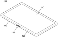
도 1은 본 발명의 일 실시예에 따른 폴더블 표시 장치를 개략적으로 나타내는 단면도이다.
도 2는 도 1의 폴더블 표시 장치의 작동예들을 나타낸 측면도이다.
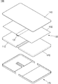
도 3은 도 1의 폴더블 표시 장치를 분해하여 개략적으로 나타낸 사시도이다.
도 4는 도 3의 폴딩부의 일부를 확대하여 나타낸 측면도이다.
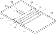
도 5는 도 3의 제1 하우징 및 제2 하우징의 배면을 나타낸 사시도이다.
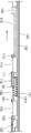
도 6a 및 도 6b는 도 5의 힌지 홀더의 작동예를 나타낸 측면 단면도이다.
도 7a 및 7b는 폴딩부의 작동예들을 나타낸 측면 단면도이다.
도 8은 본 발명의 다른 실시예에 따른 폴더블 표시 장치를 개략적으로 나타내는 측면 단면도이다.FIG. 1 is a cross-sectional view schematically showing a display device according to an embodiment of the present invention.
2 is a side view showing operation examples of the present embodiment of the present invention.
3 is a perspective view schematically showing the disassembled view of the display device of the present invention.
Fig. 4 is an enlarged side view of a part of the folding unit of Fig. 3;
Fig. 5 is a perspective view showing the back surface of the first housing and the second housing of Fig. 3;
6A and 6B are side cross-sectional views illustrating an example of operation of the hinge holder of FIG.
7A and 7B are side sectional views showing examples of operation of the folding portion.
8 is a side cross-sectional view schematically showing a foldable display device according to another embodiment of the present invention.
본 발명은 다양한 변환을 가할 수 있고 여러 가지 실시예를 가질 수 있는 바, 특정 실시예들을 도면에 예시하고 상세한 설명에 상세하게 설명하고자 한다. 본 발명의 효과 및 특징, 그리고 그것들을 달성하는 방법은 도면과 함께 상세하게 후술되어 있는 실시예들을 참조하면 명확해질 것이다. 그러나 본 발명은 이하에서 개시되는 실시예들에 한정되는 것이 아니라 다양한 형태로 구현될 수 있다.BRIEF DESCRIPTION OF THE DRAWINGS The present invention is capable of various modifications and various embodiments, and specific embodiments are illustrated in the drawings and described in detail in the detailed description. The effects and features of the present invention and methods of achieving them will be apparent with reference to the embodiments described in detail below with reference to the drawings. However, the present invention is not limited to the embodiments described below, but may be implemented in various forms.
이하의 실시예에서, 제1, 제2 등의 용어는 한정적인 의미가 아니라 하나의 구성 요소를 다른 구성 요소와 구별하는 목적으로 사용되었다. 또한, 단수의 표현은 문맥상 명백하게 다르게 뜻하지 않는 한, 복수의 표현을 포함한다. 또한, 포함하다 또는 가지다 등의 용어는 명세서상에 기재된 특징, 또는 구성요소가 존재함을 의미하는 것이고, 하나 이상의 다른 특징들 또는 구성요소가 부가될 가능성을 미리 배제하는 것은 아니다.In the following embodiments, the terms first, second, and the like are used for the purpose of distinguishing one element from another element, not the limitative meaning. Also, the singular expressions include plural expressions unless the context clearly dictates otherwise. Also, the terms include, including, etc. mean that there is a feature, or element, recited in the specification and does not preclude the possibility that one or more other features or components may be added.
또한, 도면에서는 설명의 편의를 위하여 구성 요소들이 그 크기가 과장 또는 축소될 수 있다. 예컨대, 도면에서 나타난 각 구성의 크기 및 두께는 설명의 편의를 위해 임의로 나타내었으므로, 본 발명이 반드시 도시된 바에 한정되지 않는다. 또한, 어떤 실시예가 달리 구현 가능한 경우에 특정한 공정 순서는 설명되는 순서와 다르게 수행될 수도 있다. 예를 들어, 연속하여 설명되는 두 공정이 실질적으로 동시에 수행될 수도 있고, 설명되는 순서와 반대의 순서로 진행될 수 있다.Also, in the drawings, for convenience of explanation, the components may be exaggerated or reduced in size. For example, the size and thickness of each component shown in the drawings are arbitrarily shown for convenience of explanation, and thus the present invention is not necessarily limited to those shown in the drawings. Also, if an embodiment is otherwise feasible, the particular process sequence may be performed differently than the sequence described. For example, two processes that are described in succession may be performed substantially concurrently, and may be performed in the reverse order of the order described.
이하, 첨부된 도면을 참조하여 본 발명의 실시예들을 상세히 설명하기로 하며, 도면을 참조하여 설명할 때 동일하거나 대응하는 구성 요소는 동일한 도면부호를 부여하고 이에 대한 중복되는 설명은 생략하기로 한다.Hereinafter, exemplary embodiments of the present invention will be described in detail with reference to the accompanying drawings, wherein like reference numerals refer to like or corresponding components throughout the drawings, and a duplicate description thereof will be omitted .
도 1은 본 발명의 일 실시예에 따른 폴더블 표시 장치를 개략적으로 나타내는 단면도이고, 도 2는 도 1의 폴더블 표시 장치의 작동예들을 나타낸 측면도이다.FIG. 1 is a cross-sectional view schematically showing a folder-type display apparatus according to an embodiment of the present invention, and FIG. 2 is a side view showing operation examples of the folder-type display apparatus of FIG.
도 1 및 도 2를 참조하면, 폴더블 표시 장치(100)는 제1 하우징(110)과, 제2 하우징(120)과, 폴딩부(130)와, 플렉서블 디스플레이(140)를 포함한다.1 and 2, the
제1 하우징(110)과 제2 하우징(120)은 서로 이격되도록 배치되며, 제1 하우징(110)과 제2 하우징(120)이 이격되어 마련되는 공간에는 폴딩부(130)가 설치될 수 있다.The
폴딩부(130)는 제1 하우징(110)과 제2 하우징(120)이 서로 이격된 공간에 설치될 수 있으며, 제1 하우징(110)과 제2 하우징(120)이 서로에 대해 접철 가능하도록 제1 하우징(110)과 제2 하우징(120)을 연결할 수 있다.The
플렉서블 디스플레이(140)는 접혀질 수 있는 디스플레이 패널 및 소자를 포함할 수 있다. 플렉서블 디스플레이(140)의 수축면(140c) 측은 제1 하우징(110)과, 제2 하우징(120) 및 폴딩부(130)에 의해 지지될 수 있으며, 인장면(140t) 측은 시인 가능한 영상을 구현할 수 있다.The
상세히, 플렉서블 디스플레이(140)는 일반적으로 디스플레이 장치에서 처리되는 화상, 예를 들어, 텍스트, 비디오, 사진, 2차원 또는 3차원 이미지, 아이콘 및 커서 등을 표시할 수 있다. 일 예로, 디스플레이 장치가 휴대용 컴퓨터일 경우, 이와 관련된 UI(user interface) 또는 GUI(graphic use interface) 등의 화상을 표시할 수 있다.In particular, the
또한, 플렉서블 디스플레이(140)는 접을 수 있는 플라스택재 또는 금속 호일로 형성되는 유연한 기판, 기판 상에 형성되는 화소부 및 패시베이션막을 포함할 수 있다. 이러한 플렉서블 디스플레이(140)는 유기 발광 표시 장치, 액정 표시 장치, 전기 영동 표시 장치 등일 수 있으나, 본 발명의 실시예들은 이에 한정되는 것은 아니다.In addition, the
본 발명의 실시예에 따른 폴더블 표시 장치(100)는 도 2a에 나타난 바와 같이 언-폴딩(un-folding)된 상태로 유지되거나, 도 2b에 나타난 바와 같이 소정 각도 폴딩(folding)되거나, 도 2c에 나타난 바와 같이 제1 하우징(110)과 제2 하우징(120)이 접철되어 완전히 폴딩된 상태를 유지할 수 있다.The
이와 같은 본 발명의 실시예에 따른 폴더블 표시 장치(100)의 구체적인 구성과 구조에 관하여 이하 도 3 내지 도 7을 참조하여 자세하게 설명하기로 한다.The detailed configuration and structure of the
도 3은 도 1의 폴더블 표시 장치를 분해하여 개략적으로 나타낸 사시도이고, 도 4는 도 3의 폴딩부의 일부를 확대하여 나타낸 측면도이며, 도 5는 도 3의 제1 하우징 및 제2 하우징의 배면을 나타낸 사시도이고, 도 6a 및 도 6b는 도 5의 힌지 홀더의 작동예를 나타낸 측면 단면도이다.FIG. 3 is a perspective view schematically illustrating the foldable display device of FIG. 1, FIG. 4 is an enlarged side view of a part of the folding unit of FIG. 3, and FIG. 5 is a cross- 6A and 6B are side cross-sectional views illustrating an example of operation of the hinge holder of FIG. 5. FIG.
도 3 및 도 4를 참조하면, 폴딩부(130)는 플렉서블 디스플레이(140)의 길이 방향으로 연속적으로 배치되는 복수개의 다관절 부재(131)와, 플렉서블 디스플레이(140)를 지지하는 지지판(132)과, 다관절 부재(131)와 지지판(132)을 연결하는 접착층(133)을 포함할 수 있다.3 and 4, the
다관절 부재(131)는 플라스틱 또는 금속으로 구성될 수 있으며, 소정의 탄성력을 갖도록 구성될 수도 있다. 다만, 다관절 부재(131)는 폴더블 표시 장치(100)의 반복적인 폴딩 및 언폴딩 작동에 대해 내구성을 갖기 위해 충분한 강성을 갖는 물질로 제조되는 것이 바람직하다.The
지지판(132)은 인바 합금(invar alloy)으로 구성될 수 있으나, 본 발명의 실시예들은 이에 한정되지 않는다. 예를 들어, 지지판(132)은 플렉서블 디스플레이(140)의 폴딩 및 언폴딩을 충분히 견딜 수 있는 강성을 갖는 금속 시트(metal sheet)로도 구성될 수 있다.The
상세히, 지지판(132)은 플렉서블 디스플레이(140)의 수축면(140c)을 지지할 수 있으며, 제1 하우징(110), 제2 하우징(120) 및 폴딩부(130)를 모두 덮을 수 있다. 즉, 지지판(132)은 플렉서블 디스플레이(140)의 크기에 대응하도록 구성되어 제1 하우징(110), 제2 하우징(120) 및 폴딩부(130) 상에서 플렉서블 디스플레이(140)가 차지하는 영역에 대응하는 크기를 갖도록 형성될 수 있다.The
접착층(133)은 다관절 부재(131)와 지지판(132) 사이에 개재되어 다관절 부재(131)와 지지판(132)을 접착할 수 있는 소정의 접착력을 갖는 물질로 구성될 수 있다.The
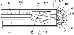
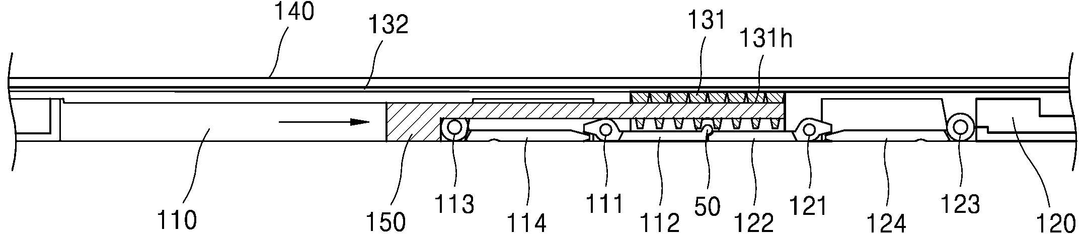
도 5와 도 6a 및 도 6b를 참조하면, 폴더블 표시 장치(100)는 폴딩부(130)의 폴딩을 구속하는 제1 위치(도 6a 참조)와, 폴딩부(130)의 폴딩을 허용하는 제2 위치(도 6b 참조) 사이에서 이동 가능한 힌지 홀더(150)를 포함할 수 있다.5 and 6A and 6B, the
이러한 힌지 홀더(150)는 폴딩부(130)를 향하는 방향으로 선형 운동 가능하도록 제1 하우징(110) 또는 제2 하우징(120)에 설치될 수 있다. 도 5 및 도 6은 힌지 홀더(150)가 제1 하우징(110)에 설치된 모습을 나타내나, 이는 설명의 편의를 위한 것으로, 힌지 홀더(150)는 제2 하우징(120)에도 설치될 수 있다.The
또한, 폴딩부(130)의 다관절 부재(131)는 힌지 홀더(150)를 수용하는 홀딩홀(131h)을 포함할 수 있다.Also, the
즉, 도 6a에 나타난 바와 같이 힌지 홀더(150)가 다관절 부재(131)의 홀딩홀(131h)에 수용될 경우, 폴딩부(130)의 폴딩이 구속되어 폴더블 표시 장치(100)의 폴딩이 구속될 수 있다.6A, when the
한편, 도 6b에 나타난 바와 같이 힌지 홀더(150)가 다관절 부재(131)의 홀딩홀(131h)에서 반출될 경우, 폴딩부(130)의 폴딩이 허용되고, 이에 따라 폴더블 표시 장치(100)의 폴딩이 허용될 수 있다.6B, folding of the
폴더블 표시 장치(100)가 이러한 힌지 홀더(150)와 같은 구성을 포함할 경우, 플렉서블 디스플레이(140)의 언-폴딩 상태를 용이하게 유지시킬 수 있게 되며, 플렉서블 디스플레이(140)가 한 방향으로만 폴딩할 수 있도록 폴딩부(130)를 구속함으로써 플렉서블 디스플레이(140)의 인장면(140t) 측이 수축되거나, 수축면(140c) 측이 인장되어 좌굴(buckling) 현상이 발생하는 것을 방지할 수 있다.It is possible to easily maintain the unfolded state of the
한편, 제1 하우징(110)은 제2 하우징(120)에 인접하는 위치에 형성되는 제1 힌지축(111)에 대해 회동 가능하도록 연결되는 제1 힌지 커버(112)를 포함할 수 있으며, 제2 하우징(120) 또한 제1 하우징(110)에 인접하는 위치에 형성되는 제2 힌지축(121)에 대해 회동 가능하도록 연결되는 제2 힌지 커버(122)를 포함할 수 있다.The
여기서, 제1 힌지 커버(112)와 제2 힌지 커버(122)는 서로에 대해 회동 가능하도록 중첩축(50)을 중심으로 중첩 연결될 수 있다. 여기서, 중첩축(50)은 별도의 부재로 마련될 수도 있으나, 이러한 중첩축(50)은 가상의 축으로써 제1 힌지 커버(112) 및 제2 힌지 커버(122)가 서로 회동 가능하도록 연결될 수도 있다. 폴딩부(130)는 이러한 제1 힌지 커버(112) 및 제2 힌지 커버(122)와 같은 구조로 인해 덮여져 제1 하우징(110) 및 제2 하우징(120)의 내부에 설치될 수 있다.Here, the
또한, 제1 하우징(110)은 제1 힌지축(111)보다 제2 하우징(120)으로부터 멀어지는 방향에 형성되는 제3 힌지축(113)과, 제1 힌지 커버(112)의 회동에 따라 제3 힌지축(113)에 대해 회동 가능하도록 연결되는 제1 하우징 커버(114)를 더 포함할 수 있다.The
제2 하우징(120) 또한 제2 힌지축(121)보다 제1 하우징(110)에서 멀어지는 방향에 형성되는 제4 힌지축(123)과, 제2 힌지 커버(122)의 회동에 따라 제4 힌지축(123)에 대해 회동 가능하도록 연결되는 제2 하우징 커버(124)를 더 포함할 수 있다.The
한편, 도 3을 다시 참조하면, 도 5, 도 6a 및 도 6b에 나타난 제1 하우징(110) 및 제2 하우징(120)의 하측면에 설치되는 모든 구성요소들은 케이스(170)에 의해 덮여질 수 있다.Referring again to FIG. 3, all the components installed on the lower sides of the
도 7a 및 7b는 폴딩부의 작동예들을 나타낸 측면 단면도이다.7A and 7B are side sectional views showing examples of operation of the folding portion.
도 7a는 힌지 홀더(150)가 홀딩홀(131h)에서 반출되어 폴딩부(130)의 폴딩을 허용하는 경우를 나타낸다. 이렇게 폴딩부(130)가 폴딩되면, 제1 힌지 커버(112)와 제2 힌지 커버(122)는 폴딩부(130)의 폴딩에 따라 중첩축(50)을 중심으로 함께 회동하게 된다.7A shows a case in which the
도 7b는 폴딩부(130)가 완전히 폴딩되어 복수개의 다관절 부재(131)가 서로 밀착되는 경우를 나타낸다. 즉, 폴딩부(130)가 완전히 폴딩되면, 제1 하우징(110)과 제2 하우징(120)이 접철되며, 이에 따라 플렉서블 디스플레이(140)의 수축면(140c)은 수축하며, 인장면(140t)은 인장되어 폴더블 표시 장치(100)가 폴딩될 수 있다.7B shows a case where the
도 8은 본 발명의 다른 실시예에 따른 폴더블 표시 장치를 개략적으로 나타내는 측면 단면도이다.8 is a side cross-sectional view schematically showing a foldable display device according to another embodiment of the present invention.
도 8을 참조하면, 제1 하우징(210)은 일단이 제2 하우징(220)에 인접하는 위치에 형성되는 제1 힌지축(211)에 대해 회동 가능하도록 연결되는 힌지 커버(212)를 포함하고, 제2 하우징(220)은 힌지 커버(212)의 타단이 제2 하우징(220)의 길이 방향을 따라 슬라이딩 가능하도록 인도하는 가이드홀(221)을 포함할 수 있다.8, the
또한, 제1 하우징(210)은 제1 힌지축(211)보다 제2 하우징(120)에서 멀어지는 방향에 형성되는 제2 힌지축(213)과, 힌지 커버(212)의 회동에 따라 제2 힌지축(213)에 대해 회동 가능하도록 연결되는 하우징 커버(214)를 더 포함할 수 있다.The
도 8은 전술한 도 7a에 나타난 폴더블 표시 장치(100)에 대한 변형예로, 도시되지는 않았으나 도 8에 나타난 본 발명의 다른 실시예에 관한 폴더블 표시 장치(200)의 경우도 도 7b에 나타난 본 발명의 일 실시예에 관한 폴더블 표시 장치(100)의 경우와 같이 완전히 폴딩될 수 있다.8 is a modification of the above-described
즉, 도 8의 가이드홀(221)에 수용되는 힌지 커버(212)의 타단은 폴딩부(230)의 폴딩에 따라 슬라이딩될 수 있으며, 폴더블 표시 장치(200)가 완전히 폴딩되는 경우에는 가이드홀(221)의 폴딩 위치(221f)에 위치할 수 있으며, 반면 폴더블 표시 장치(200)가 언-폴딩 되는 경우에는 언-폴딩 위치(221u)에 위치할 수 있다.That is, the other end of the
이러한 힌지 커버(212)의 구동에 따라, 제1 하우징(210)과 제2 하우징(210)은 도 7b에 나타나 바와 같이 서로 접철되는 위치와 도 6a 및 도 6b에 나타난 바와 같이 완전히 언-폴딩되는 위치 사이에서 서로 회동 가능하도록 구성될 수 있다.As the
이와 같이 본 발명은 도면에 도시된 일 실시예를 참고로 하여 설명하였으나 이는 예시적인 것에 불과하며 당해 분야에서 통상의 지식을 가진 자라면 이로부터 다양한 변형 및 실시예의 변형이 가능하다는 점을 이해할 것이다. 따라서, 본 발명의 진정한 기술적 보호 범위는 첨부된 특허청구범위의 기술적 사상에 의하여 정해져야 할 것이다.While the present invention has been particularly shown and described with reference to exemplary embodiments thereof, it is to be understood that the invention is not limited to the exemplary embodiments, and that various changes and modifications may be made therein without departing from the scope of the present invention. Accordingly, the true scope of the present invention should be determined by the technical idea of the appended claims.
50: 중첩축 122: 제2 힌지 커버
100: 폴더블 표시 장치 123: 제4 힌지축
110: 제1 하우징 124: 제2 하우징 커버
111: 제1 힌지축 130: 폴딩부
112: 제1 힌지 커버 131: 다관절 부재
113: 제3 힌지축 132: 지지판
114: 제1 하우징 커버 133: 접착층
120: 제2 하우징 140: 플렉서블 디스플레이
121: 제2 힌지축 150: 힌지 홀더50: overlap axis 122: second hinge cover
100: Foldable display device 123: Fourth hinge axis
110: first housing 124: second housing cover
111: first hinge shaft 130: folding part
112: first hinge cover 131: multi-joint member
113: third hinge shaft 132: support plate
114: first housing cover 133: adhesive layer
120: second housing 140: flexible display
121: second hinge shaft 150: hinge holder
Claims (35)
상기 제1 하우징과 이격되어 배치되는 제2 하우징;
상기 제1 하우징과 상기 제2 하우징 사이에 배치되고, 서로 연결되는 복수개의 관절을 포함하는 다관절 구조물; 및
상기 제1 하우징과 결합되는 슬라이딩 구조물을 포함하고,
상기 슬라이딩 구조물은 상기 제1 하우징이 상기 슬라이딩 구조물에 대하여 상대적으로 이동하는 제1 방향과 반대인 제2 방향으로 상기 제1 하우징에 대하여 상대적으로 이동하도록 상기 제1 하우징과 결합되고,
상기 제2 방향은 상기 다관절 구조물을 향하는 방향 또는 상기 다관절 구조물로부터 멀어지는 방향이고,
상기 제1 하우징은 제1 측 및 상기 제1 측의 반대편인 제2 측을 갖고, 상기 다관절 구조물은 제3 측 및 상기 제3 측의 반대편인 제4 측을 갖고, 상기 제2 하우징은 제5 측 및 상기 제5 측의 반대편인 제6 측을 갖고,
상기 다관절 구조물이 펼쳐졌을 때, 상기 제1 측, 상기 제3 측, 및 상기 제5 측은 같은 편에 위치하고, 상기 제2 측, 상기 제4 측, 및 상기 제6 측은 같은 편에 위치하는 폴더블 표시 장치용 케이스 조립체.A first housing;
A second housing disposed apart from the first housing;
A multi-joint structure disposed between the first housing and the second housing and including a plurality of joints connected to each other; And
And a sliding structure coupled to the first housing,
Wherein the sliding structure is coupled with the first housing such that the sliding structure moves relative to the first housing in a second direction opposite to the first direction in which the first housing moves relative to the sliding structure,
Wherein the second direction is a direction toward the multi-joint structure or a direction away from the multi-joint structure,
Wherein said first housing has a first side and a second side opposite said first side, said multifold structure having a third side and a fourth side opposite said third side, 5 and a sixth side opposite to the fifth side,
Wherein the first side, the third side, and the fifth side are located on the same side when the multi-joint structure is unfolded, and the second side, the fourth side, and the sixth side are located on the same side A display assembly for a display device.
상기 다관절 구조물이 펼쳐진 상태에서, 상기 제2 측, 상기 제4 측 및 상기 제6 측은 평탄한 폴더블 표시 장치용 케이스 조립체.The method according to claim 1,
Wherein the second side, the fourth side and the sixth side are flat when the multi-joint structure is unfolded.
상기 제2 측 및 상기 제6 측은 서로 반대편에 배치되고 상기 제1 측 및 상기 제5 측은 서로 마주 보게 배치되도록 상기 다관절 구조물이 접히도록 구성되고,
상기 관절의 폭은 상기 제3 측에서 상기 제4 측을 향하는 방향을 따라 증가하는 폴더블 표시 장치용 케이스 조립체.The method according to claim 1,
The multi-joint structure is configured to be folded so that the second side and the sixth side are disposed opposite to each other and the first side and the fifth side are disposed to face each other,
And the width of the joint increases along a direction from the third side toward the fourth side.
상기 관절은 사다리꼴 형상의 단면을 갖는 폴더블 표시 장치용 케이스 조립체.The method of claim 3,
Wherein the joint has a trapezoidal cross section.
상기 제2 측 및 상기 제6 측은 서로 반대편에 배치되고 상기 제1 측 및 상기 제5 측은 서로 마주 보게 배치되도록 상기 다관절 구조물이 접혔을 때, 상기 다관절 구조물은 반원 형상의 단면을 갖는 폴더블 표시 장치용 케이스 조립체.The method of claim 3,
When the multi-joint structure is folded such that the second side and the sixth side are disposed opposite to each other and the first side and the fifth side are opposed to each other, the multifunctional structure has a semi-circular cross- Display assembly.
상기 제2 측 및 상기 제6 측은 서로 반대편에 배치되고 상기 제1 측 및 상기 제5 측은 서로 마주 보게 배치되도록 상기 다관절 구조물이 접히도록 구성되고,
상기 다관절 구조물이 펼쳐졌을 때, 상기 제4 측이 상기 제3 측보다 평탄한 폴더블 표시 장치용 케이스 조립체.The method according to claim 1,
The multi-joint structure is configured to be folded so that the second side and the sixth side are disposed opposite to each other and the first side and the fifth side are disposed to face each other,
Wherein the fourth side is flatter than the third side when the multi-joint structure is unfolded.
상기 슬라이딩 구조물의 적어도 일부는 경성의 플레이트인 폴더블 표시 장치용 케이스 조립체.The method according to claim 1,
Wherein at least a part of the sliding structure is a rigid plate.
상기 슬라이딩 구조물은 제1 가이드부를 갖고,
상기 다관절 구조물은 상기 슬라이딩 구조물의 상기 제1 가이드부와 대응하는 제2 가이드부를 갖고,
상기 다관절 구조물이 펼쳐지거나 접혀지기 위해서, 상기 제1 가이드부 및 상기 제2 가이드부는 상기 슬라이딩 구조물과 상기 다관절 구조물이 서로 가이드 하면서 서로 반대 방향으로 상대적으로 이동할 수 있도록 구성되는 폴더블 표시 장치용 케이스 조립체.The method according to claim 1,
Wherein the sliding structure has a first guide portion,
Wherein the multi-joint structure has a second guide portion corresponding to the first guide portion of the sliding structure,
Wherein the first guide part and the second guide part are configured to move relative to each other while guiding the sliding structure and the multifunctional structure so that the multifunctional structure is unfolded or folded, Case assembly.
상기 다관절 구조물이 펼쳐졌을 때, 상기 제2 가이드부에 상기 제1 가이드부가 삽입된 상태인 폴더블 표시 장치용 케이스 조립체.9. The method of claim 8,
Wherein when the multi-joint structure is unfolded, the first guide portion is inserted into the second guide portion.
상기 다관절 구조물이 접혔을 때, 상기 제2 가이드부에 상기 제1 가이드부가 삽입되지 않은 상태인 폴더블 표시 장치용 케이스 조립체.10. The method of claim 9,
Wherein when the multi-joint structure is folded, the first guide portion is not inserted into the second guide portion.
상기 관절은 상기 다관절 구조물이 펼쳐졌을 때 상기 제1 가이드부가 삽입되는 서브 가이드부를 갖고,
상기 제2 가이드부는 상기 서브 가이드부를 포함하는 폴더블 표시 장치용 케이스 조립체.10. The method of claim 9,
Wherein the joint has a sub-guide portion into which the first guide portion is inserted when the multi-joint structure is unfolded,
And the second guide portion includes the sub guide portion.
상기 서브 가이드부는 사다리꼴 형상의 단면을 갖는 폴더블 표시 장치용 케이스 조립체.12. The method of claim 11,
Wherein the sub guide portion has a trapezoidal cross section.
상기 다관절 구조물이 펼쳐졌을 때, 상기 다관절 구조물 및 상기 슬라이딩 구조물은 서로 겹치는 상태인 폴더블 표시 장치용 케이스 조립체.The method according to claim 1,
Wherein the multi-joint structure and the sliding structure overlap each other when the multi-joint structure is unfolded.
상기 제2 측 및 상기 제6 측은 서로 반대편에 배치되고 상기 제1 측 및 상기 제5 측은 서로 마주 보게 배치되도록 상기 다관절 구조물이 접혔을 때, 상기 다관절 구조물 및 상기 슬라이딩 구조물은 서로 겹치지 않은 상태인 폴더블 표시 장치용 케이스 조립체.14. The method of claim 13,
When the multi-joint structure is folded such that the second side and the sixth side are disposed opposite to each other and the first side and the fifth side are opposed to each other, the multi-joint structure and the sliding structure are not overlapped with each other Wherein the housing assembly comprises:
상기 다관절 구조물이 펼쳐지기 위해서, 상기 슬라이딩 구조물은 상기 다관절 구조물을 향하는 상기 방향으로 상기 제1 하우징에 대하여 상대적으로 이동되는 폴더블 표시 장치용 케이스 조립체.The method according to claim 1,
Wherein the sliding structure is relatively moved with respect to the first housing in the direction toward the multi-joint structure so that the multi-joint structure is unfolded.
상기 제2 측 및 상기 제6 측은 서로 반대편에 배치되고 상기 제1 측 및 상기 제5 측은 서로 마주 보게 배치되도록 상기 다관절 구조물이 접혀지기 위해서, 상기 슬라이딩 구조물은 상기 다관절 구조물로부터 멀어지는 상기 방향으로 상기 제1 하우징에 대하여 상대적으로 이동되는 폴더블 표시 장치용 케이스 조립체.16. The method of claim 15,
In order for the multifilament structure to be folded so that the second side and the sixth side are disposed opposite to each other and the first side and the fifth side are opposed to each other, the sliding structure is moved in the direction away from the multi- And is moved relative to the first housing.
상기 다관절 구조물은 상기 다관절 구조물의 중심 부분의 우측에 위치하는 제1 부분 및 상기 중심 부분의 좌측에 위치하는 제2 부분을 포함하고,
상기 제1 부분 및 상기 제2 부분은 동시에 접히거나 펴지는 폴더블 표시 장치용 케이스 조립체.The method according to claim 1,
Wherein the multi-joint structure includes a first portion located on the right side of the center portion of the multi-joint structure and a second portion located on the left side of the center portion,
Wherein the first portion and the second portion are folded or unfolded at the same time.
상기 제1 하우징과 이격되어 배치되는 제2 하우징;
상기 제1 하우징과 상기 제2 하우징 사이에 배치되고, 서로 연결되는 복수개의 관절을 포함하는 다관절 구조물; 및
상기 제1 하우징과 결합되는 슬라이딩 구조물을 포함하고,
상기 슬라이딩 구조물은 상기 제1 하우징이 상기 슬라이딩 구조물에 대하여 상대적으로 이동하는 제1 방향과 반대인 제2 방향으로 상기 제1 하우징에 대하여 상대적으로 이동하도록 상기 제1 하우징과 결합되고,
상기 제2 방향은 상기 다관절 구조물을 향하는 방향 또는 상기 다관절 구조물로부터 멀어지는 방향이고,
상기 제1 하우징은 제1 측 및 상기 제1 측의 반대편인 제2 측을 갖고, 상기 다관절 구조물은 제3 측 및 상기 제3 측의 반대편인 제4 측을 갖고, 상기 제2 하우징은 제5 측 및 상기 제5 측의 반대편인 제6 측을 갖고,
상기 다관절 구조물이 펼쳐졌을 때, 상기 제1 측, 상기 제3 측, 및 상기 제5 측은 같은 편에 위치하고, 상기 제2 측, 상기 제4 측, 및 상기 제6 측은 같은 편에 위치하고,
상기 제2 측, 상기 제4 측, 및 상기 제6 측 상에 연속적으로 위치하고, 상기 제2 측, 상기 제4 측, 및 상기 제6 측과 대향하는 제7 측 및 상기 제7 측의 반대편인 제8 측을 갖는 가요성 표시 패널을 더 포함하고,
상기 제2 측 및 상기 제6 측은 서로 반대편에 배치되고 상기 제1 측 및 상기 제5 측은 서로 마주 보게 배치되도록 상기 다관절 구조물이 접혔을 때, 상기 다관절 구조물에 대응하는 상기 제8 측의 일부에는 인장력이 가해지는 폴더블 표시 장치.A first housing;
A second housing disposed apart from the first housing;
A multi-joint structure disposed between the first housing and the second housing and including a plurality of joints connected to each other; And
And a sliding structure coupled to the first housing,
Wherein the sliding structure is coupled with the first housing such that the sliding structure moves relative to the first housing in a second direction opposite to the first direction in which the first housing moves relative to the sliding structure,
Wherein the second direction is a direction toward the multi-joint structure or a direction away from the multi-joint structure,
Wherein said first housing has a first side and a second side opposite said first side, said multifold structure having a third side and a fourth side opposite said third side, 5 and a sixth side opposite to the fifth side,
Wherein the first side, the third side, and the fifth side are located on the same side, and the second side, the fourth side, and the sixth side are on the same side when the multi-joint structure is unfolded,
And a sixth side that is located on the second side, the fourth side, and the sixth side, and which is opposite to the second side, the fourth side, and the sixth side, Further comprising a flexible display panel having an eighth side,
Wherein when the multifunctional structure is folded such that the second side and the sixth side are disposed opposite to each other and the first side and the fifth side are opposed to each other, a portion of the eighth side corresponding to the multifunctional structure And a tensile force is exerted on the movable member.
상기 다관절 구조물이 펼쳐진 상태에서, 상기 제2 측, 상기 제4 측 및 상기 제6 측은 평탄한 폴더블 표시 장치.19. The method of claim 18,
Wherein the second side, the fourth side and the sixth side are flat in a state in which the multi-joint structure is unfolded.
상기 제2 측 및 상기 제6 측은 서로 반대편에 배치되고 상기 제1 측 및 상기 제5 측은 서로 마주 보게 배치되도록 상기 다관절 구조물이 접히도록 구성되고,
상기 관절의 폭은 상기 제3 측에서 상기 제4 측을 향하는 방향을 따라 증가하는 폴더블 표시 장치.19. The method of claim 18,
The multi-joint structure is configured to be folded so that the second side and the sixth side are disposed opposite to each other and the first side and the fifth side are disposed to face each other,
And the width of the joint increases along a direction from the third side toward the fourth side.
상기 관절은 사다리꼴 형상의 단면을 갖는 폴더블 표시 장치.21. The method of claim 20,
Wherein the joints have a trapezoidal cross section.
상기 제2 측 및 상기 제6 측은 서로 반대편에 배치되고 상기 제1 측 및 상기 제5 측은 서로 마주 보게 배치되도록 상기 다관절 구조물이 접혔을 때, 상기 다관절 구조물은 반원 형상의 단면을 갖는 폴더블 표시 장치.21. The method of claim 20,
When the multi-joint structure is folded such that the second side and the sixth side are disposed opposite to each other and the first side and the fifth side are opposed to each other, the multifunctional structure has a semi-circular cross- Display device.
상기 제2 측 및 상기 제6 측은 서로 반대편에 배치되고 상기 제1 측 및 상기 제5 측은 서로 마주 보게 배치되도록 상기 다관절 구조물이 접히도록 구성되고,
상기 다관절 구조물이 펼쳐졌을 때, 상기 제4 측이 상기 제3 측보다 평탄한 폴더블 표시 장치.19. The method of claim 18,
The multi-joint structure is configured to be folded so that the second side and the sixth side are disposed opposite to each other and the first side and the fifth side are disposed to face each other,
Wherein the fourth side is flatter than the third side when the multi-joint structure is unfolded.
상기 슬라이딩 구조물의 적어도 일부는 경성의 플레이트인 폴더블 표시 장치.19. The method of claim 18,
Wherein at least a part of the sliding structure is a rigid plate.
상기 슬라이딩 구조물은 제1 가이드부를 갖고,
상기 다관절 구조물은 상기 슬라이딩 구조물의 상기 제1 가이드부와 대응하는 제2 가이드부를 갖고,
상기 다관절 구조물이 펼쳐지거나 접혀지기 위해서, 상기 제1 가이드부 및 상기 제2 가이드부는 상기 슬라이딩 구조물과 상기 다관절 구조물이 서로 가이드 하면서 서로 반대 방향으로 상대적으로 이동할 수 있도록 구성되는 폴더블 표시 장치.19. The method of claim 18,
Wherein the sliding structure has a first guide portion,
Wherein the multi-joint structure has a second guide portion corresponding to the first guide portion of the sliding structure,
Wherein the first guide part and the second guide part are configured to relatively move in a direction opposite to each other while guiding the sliding structure and the multifunctional structure so that the multifunctional structure is unfolded or folded.
상기 다관절 구조물이 펼쳐졌을 때, 상기 제2 가이드부에 상기 제1 가이드부가 삽입된 상태인 폴더블 표시 장치.26. The method of claim 25,
Wherein when the multi-joint structure is unfolded, the first guide portion is inserted into the second guide portion.
상기 다관절 구조물이 접혔을 때, 상기 제2 가이드부에 상기 제1 가이드부가 삽입되지 않은 상태인 폴더블 표시 장치.27. The method of claim 26,
Wherein when the multi-joint structure is folded, the first guide portion is not inserted into the second guide portion.
상기 관절은 상기 다관절 구조물이 펼쳐졌을 때 상기 제1 가이드부가 삽입되는 서브 가이드부를 갖고,
상기 제2 가이드부는 상기 서브 가이드부를 포함하는 폴더블 표시 장치.27. The method of claim 26,
Wherein the joint has a sub-guide portion into which the first guide portion is inserted when the multi-joint structure is unfolded,
And the second guide portion includes the sub guide portion.
상기 서브 가이드부는 사다리꼴 형상의 단면을 갖는 폴더블 표시 장치.29. The method of claim 28,
And the sub guide portion has a trapezoidal cross section.
상기 다관절 구조물이 펼쳐졌을 때, 상기 다관절 구조물 및 상기 슬라이딩 구조물은 서로 겹치는 상태인 폴더블 표시 장치.19. The method of claim 18,
Wherein when the multi-joint structure is unfolded, the multi-joint structure and the sliding structure overlap each other.
상기 제2 측 및 상기 제6 측은 서로 반대편에 배치되고 상기 제1 측 및 상기 제5 측은 서로 마주 보게 배치되도록 상기 다관절 구조물이 접혔을 때, 상기 다관절 구조물 및 상기 슬라이딩 구조물은 서로 겹치지 않은 상태인 폴더블 표시 장치.31. The method of claim 30,
When the multi-joint structure is folded such that the second side and the sixth side are disposed opposite to each other and the first side and the fifth side are opposed to each other, the multi-joint structure and the sliding structure are not overlapped with each other In-one display device.
상기 다관절 구조물이 펼쳐지기 위해서, 상기 슬라이딩 구조물은 상기 다관절 구조물을 향하는 상기 방향으로 상기 제1 하우징에 대하여 상대적으로 이동되는 폴더블 표시 장치.19. The method of claim 18,
Wherein the sliding structure is relatively moved with respect to the first housing in the direction toward the multi-joint structure so that the multi-joint structure is unfolded.
상기 제2 측 및 상기 제6 측은 서로 반대편에 배치되고 상기 제1 측 및 상기 제5 측은 서로 마주 보게 배치되도록 상기 다관절 구조물이 접혀지기 위해서, 상기 슬라이딩 구조물은 상기 다관절 구조물로부터 멀어지는 상기 방향으로 상기 제1 하우징에 대하여 상대적으로 이동되는 폴더블 표시 장치.33. The method of claim 32,
In order for the multifilament structure to be folded so that the second side and the sixth side are disposed opposite to each other and the first side and the fifth side are opposed to each other, the sliding structure is moved in the direction away from the multi- And is moved relative to the first housing.
상기 다관절 구조물은 상기 다관절 구조물의 중심 부분의 우측에 위치하는 제1 부분 및 상기 중심 부분의 좌측에 위치하는 제2 부분을 포함하고,
상기 제1 부분 및 상기 제2 부분은 동시에 접히거나 펴지는 폴더블 표시 장치.19. The method of claim 18,
Wherein the multi-joint structure includes a first portion located on the right side of the center portion of the multi-joint structure and a second portion located on the left side of the center portion,
Wherein the first portion and the second portion are folded or unfolded at the same time.
상기 제1 하우징과 이격되어 배치되는 제2 하우징;
상기 제1 하우징과 상기 제2 하우징 사이에 배치되고, 서로 연결되는 복수개의 관절을 포함하는 다관절 구조물; 및
상기 다관절 구조물에 근접하거나 상기 다관절 구조물로부터 멀어지도록 상기 제1 하우징과 슬라이딩 가능하도록 상기 제1 하우징에 결합하는 슬라이딩 구조물을 포함하는 폴더블 표시 장치용 케이스 조립체.A first housing;
A second housing disposed apart from the first housing;
A multi-joint structure disposed between the first housing and the second housing and including a plurality of joints connected to each other; And
And a sliding structure that engages with the first housing to be slidable with respect to the first housing such that the sliding structure approaches or is away from the multi-joint structure.
Priority Applications (2)
| Application Number | Priority Date | Filing Date | Title |
|---|---|---|---|
| KR1020180099430A KR101969065B1 (en) | 2018-08-24 | 2018-08-24 | Case assembly for out foldable display apparatus and out foldable display apparatus |
| KR1020190040291A KR102293734B1 (en) | 2018-08-24 | 2019-04-05 | Foldable apparatus |
Applications Claiming Priority (1)
| Application Number | Priority Date | Filing Date | Title |
|---|---|---|---|
| KR1020180099430A KR101969065B1 (en) | 2018-08-24 | 2018-08-24 | Case assembly for out foldable display apparatus and out foldable display apparatus |
Related Parent Applications (1)
| Application Number | Title | Priority Date | Filing Date |
|---|---|---|---|
| KR1020150160452A Division KR102421579B1 (en) | 2015-11-16 | 2015-11-16 | Foldable display apparatus |
Related Child Applications (1)
| Application Number | Title | Priority Date | Filing Date |
|---|---|---|---|
| KR1020190040291A Division KR102293734B1 (en) | 2018-08-24 | 2019-04-05 | Foldable apparatus |
Publications (2)
| Publication Number | Publication Date |
|---|---|
| KR20180098504A true KR20180098504A (en) | 2018-09-04 |
| KR101969065B1 KR101969065B1 (en) | 2019-08-14 |
Family
ID=63598340
Family Applications (1)
| Application Number | Title | Priority Date | Filing Date |
|---|---|---|---|
| KR1020180099430A Active KR101969065B1 (en) | 2018-08-24 | 2018-08-24 | Case assembly for out foldable display apparatus and out foldable display apparatus |
Country Status (1)
| Country | Link |
|---|---|
| KR (1) | KR101969065B1 (en) |
Cited By (6)
| Publication number | Priority date | Publication date | Assignee | Title |
|---|---|---|---|---|
| EP3680749A3 (en) * | 2019-01-08 | 2020-10-21 | Samsung Display Co., Ltd. | Foldable device |
| CN111862804A (en) * | 2019-04-29 | 2020-10-30 | 三星显示有限公司 | Folding member and display device including the same |
| CN111986568A (en) * | 2019-05-23 | 2020-11-24 | 三星显示有限公司 | Foldable display device |
| US11039235B2 (en) | 2019-03-15 | 2021-06-15 | Samsung Display Co., Ltd. | Display device |
| US11169580B2 (en) | 2019-07-29 | 2021-11-09 | Samsung Display Co., Ltd. | Display device |
| US11644864B2 (en) | 2020-08-05 | 2023-05-09 | Samsung Display Co., Ltd. | Display device |
Families Citing this family (2)
| Publication number | Priority date | Publication date | Assignee | Title |
|---|---|---|---|---|
| KR20220080761A (en) | 2020-12-07 | 2022-06-15 | 삼성디스플레이 주식회사 | Display device |
| KR20230071928A (en) | 2021-11-16 | 2023-05-24 | 삼성디스플레이 주식회사 | Display device |
Citations (2)
| Publication number | Priority date | Publication date | Assignee | Title |
|---|---|---|---|---|
| US20030026068A1 (en) * | 2001-07-31 | 2003-02-06 | Wen-Sung Tsai | Portable computing device with foldable display panels |
| KR20140026547A (en) * | 2011-06-03 | 2014-03-05 | 마이크로소프트 코포레이션 | Flexible display flexure assembly |
-
2018
- 2018-08-24 KR KR1020180099430A patent/KR101969065B1/en active Active
Patent Citations (2)
| Publication number | Priority date | Publication date | Assignee | Title |
|---|---|---|---|---|
| US20030026068A1 (en) * | 2001-07-31 | 2003-02-06 | Wen-Sung Tsai | Portable computing device with foldable display panels |
| KR20140026547A (en) * | 2011-06-03 | 2014-03-05 | 마이크로소프트 코포레이션 | Flexible display flexure assembly |
Cited By (14)
| Publication number | Priority date | Publication date | Assignee | Title |
|---|---|---|---|---|
| EP4503582A3 (en) * | 2019-01-08 | 2025-04-23 | Samsung Display Co., Ltd. | Foldable device |
| EP4503582A2 (en) | 2019-01-08 | 2025-02-05 | Samsung Display Co., Ltd. | Foldable device |
| EP3680749A3 (en) * | 2019-01-08 | 2020-10-21 | Samsung Display Co., Ltd. | Foldable device |
| US12164332B2 (en) | 2019-01-08 | 2024-12-10 | Samsung Display Co., Ltd. | Foldable device |
| US11204627B2 (en) | 2019-01-08 | 2021-12-21 | Samsung Display Co., Ltd. | Foldable device |
| US11582543B2 (en) | 2019-03-15 | 2023-02-14 | Samsung Display Co., Ltd. | Display device |
| US11039235B2 (en) | 2019-03-15 | 2021-06-15 | Samsung Display Co., Ltd. | Display device |
| US10908638B2 (en) | 2019-04-29 | 2021-02-02 | Samsung Display Co., Ltd. | Folding member and display device including the same |
| CN111862804B (en) * | 2019-04-29 | 2024-11-15 | 三星显示有限公司 | Folding component and display device including the same |
| CN111862804A (en) * | 2019-04-29 | 2020-10-30 | 三星显示有限公司 | Folding member and display device including the same |
| US11516932B2 (en) | 2019-05-23 | 2022-11-29 | Samsung Display Co., Ltd. | Foldable display device |
| CN111986568A (en) * | 2019-05-23 | 2020-11-24 | 三星显示有限公司 | Foldable display device |
| US11169580B2 (en) | 2019-07-29 | 2021-11-09 | Samsung Display Co., Ltd. | Display device |
| US11644864B2 (en) | 2020-08-05 | 2023-05-09 | Samsung Display Co., Ltd. | Display device |
Also Published As
| Publication number | Publication date |
|---|---|
| KR101969065B1 (en) | 2019-08-14 |
Similar Documents
| Publication | Publication Date | Title |
|---|---|---|
| KR20170057500A (en) | Foldable display apparatus | |
| KR20180098504A (en) | Case assembly for foldable display apparatus and foldable display apparatus | |
| US11119534B2 (en) | Foldable display device | |
| KR102362096B1 (en) | Display device | |
| US11385686B2 (en) | Electronic devices with flexible displays and hinges | |
| CN207115888U (en) | Fold mechanism and terminal | |
| US10487550B2 (en) | Support device for foldable flexible screen and a display device using the same | |
| CN108028029B (en) | flexible device | |
| CN110770814B (en) | Folding mechanism and terminal | |
| US9179559B1 (en) | Foldable display apparatus | |
| KR20160035146A (en) | Foldable display apparatus | |
| US20190200470A1 (en) | Foldable display device | |
| KR20160083318A (en) | Foldable display apparatus | |
| US20220248550A1 (en) | Electronic device | |
| US20200037433A1 (en) | Foldable display device | |
| CN210183377U (en) | Electronic device | |
| US20240023261A1 (en) | Foldable display apparatus | |
| KR20190040156A (en) | Foldable apparatus | |
| CN114724458A (en) | Display device | |
| CN119687346B (en) | Roll-up screen device and electronic equipment | |
| US11029725B2 (en) | Foldable folio | |
| KR20260045979A (en) | Slidable device and display apparatus including the same | |
| CN116964540A (en) | A display component and a foldable device including the display component | |
| CN118262616A (en) | Display device | |
| CN113007207A (en) | Display device |
Legal Events
| Date | Code | Title | Description |
|---|---|---|---|
| A107 | Divisional application of patent | ||
| A201 | Request for examination | ||
| PA0107 | Divisional application |
St.27 status event code: A-0-1-A10-A18-div-PA0107 St.27 status event code: A-0-1-A10-A16-div-PA0107 |
|
| PA0201 | Request for examination |
St.27 status event code: A-1-2-D10-D11-exm-PA0201 |
|
| PG1501 | Laying open of application |
St.27 status event code: A-1-1-Q10-Q12-nap-PG1501 |
|
| A302 | Request for accelerated examination | ||
| PA0302 | Request for accelerated examination |
St.27 status event code: A-1-2-D10-D17-exm-PA0302 St.27 status event code: A-1-2-D10-D16-exm-PA0302 |
|
| D13-X000 | Search requested |
St.27 status event code: A-1-2-D10-D13-srh-X000 |
|
| D14-X000 | Search report completed |
St.27 status event code: A-1-2-D10-D14-srh-X000 |
|
| E902 | Notification of reason for refusal | ||
| PE0902 | Notice of grounds for rejection |
St.27 status event code: A-1-2-D10-D21-exm-PE0902 |
|
| E13-X000 | Pre-grant limitation requested |
St.27 status event code: A-2-3-E10-E13-lim-X000 |
|
| P11-X000 | Amendment of application requested |
St.27 status event code: A-2-2-P10-P11-nap-X000 |
|
| P13-X000 | Application amended |
St.27 status event code: A-2-2-P10-P13-nap-X000 |
|
| R18-X000 | Changes to party contact information recorded |
St.27 status event code: A-3-3-R10-R18-oth-X000 |
|
| E701 | Decision to grant or registration of patent right | ||
| PE0701 | Decision of registration |
St.27 status event code: A-1-2-D10-D22-exm-PE0701 |
|
| PA0107 | Divisional application |
St.27 status event code: A-0-1-A10-A18-div-PA0107 St.27 status event code: A-0-1-A10-A16-div-PA0107 |
|
| GRNT | Written decision to grant | ||
| PR0701 | Registration of establishment |
St.27 status event code: A-2-4-F10-F11-exm-PR0701 |
|
| PR1002 | Payment of registration fee |
St.27 status event code: A-2-2-U10-U11-oth-PR1002 Fee payment year number: 1 |
|
| PG1601 | Publication of registration |
St.27 status event code: A-4-4-Q10-Q13-nap-PG1601 |
|
| PR1001 | Payment of annual fee |
St.27 status event code: A-4-4-U10-U11-oth-PR1001 Fee payment year number: 4 |
|
| PR1001 | Payment of annual fee |
St.27 status event code: A-4-4-U10-U11-oth-PR1001 Fee payment year number: 5 |
|
| PR1001 | Payment of annual fee |
St.27 status event code: A-4-4-U10-U11-oth-PR1001 Fee payment year number: 6 |
|
| PR1001 | Payment of annual fee |
St.27 status event code: A-4-4-U10-U11-oth-PR1001 Fee payment year number: 7 |
|
| PR1001 | Payment of annual fee |
St.27 status event code: A-4-4-U10-U11-oth-PR1001 Fee payment year number: 8 |
|
| U11 | Full renewal or maintenance fee paid |
Free format text: ST27 STATUS EVENT CODE: A-4-4-U10-U11-OTH-PR1001 (AS PROVIDED BY THE NATIONAL OFFICE) Year of fee payment: 8 |