US11515568B2 - Laminated battery and manufacturing method of laminated battery - Google Patents
Laminated battery and manufacturing method of laminated battery Download PDFInfo
- Publication number
- US11515568B2 US11515568B2 US16/711,437 US201916711437A US11515568B2 US 11515568 B2 US11515568 B2 US 11515568B2 US 201916711437 A US201916711437 A US 201916711437A US 11515568 B2 US11515568 B2 US 11515568B2
- Authority
- US
- United States
- Prior art keywords
- positive electrode
- negative electrode
- composite material
- portions
- sheet
- Prior art date
- Legal status (The legal status is an assumption and is not a legal conclusion. Google has not performed a legal analysis and makes no representation as to the accuracy of the status listed.)
- Active, expires
Links
- 238000004519 manufacturing process Methods 0.000 title claims abstract description 48
- 239000002131 composite material Substances 0.000 claims abstract description 237
- 239000007784 solid electrolyte Substances 0.000 claims description 125
- 239000007773 negative electrode material Substances 0.000 claims description 14
- 239000011248 coating agent Substances 0.000 claims description 8
- 238000000576 coating method Methods 0.000 claims description 8
- HBBGRARXTFLTSG-UHFFFAOYSA-N Lithium ion Chemical compound [Li+] HBBGRARXTFLTSG-UHFFFAOYSA-N 0.000 description 17
- 229910001416 lithium ion Inorganic materials 0.000 description 17
- 238000003475 lamination Methods 0.000 description 13
- 238000000034 method Methods 0.000 description 13
- 239000008151 electrolyte solution Substances 0.000 description 10
- WHXSMMKQMYFTQS-UHFFFAOYSA-N Lithium Chemical compound [Li] WHXSMMKQMYFTQS-UHFFFAOYSA-N 0.000 description 9
- 229910052744 lithium Inorganic materials 0.000 description 9
- 239000007787 solid Substances 0.000 description 9
- 239000003792 electrolyte Substances 0.000 description 8
- -1 graphite Chemical class 0.000 description 7
- 150000003839 salts Chemical class 0.000 description 7
- 239000011230 binding agent Substances 0.000 description 6
- 239000011244 liquid electrolyte Substances 0.000 description 6
- 229910003480 inorganic solid Inorganic materials 0.000 description 5
- 238000010030 laminating Methods 0.000 description 5
- 238000000465 moulding Methods 0.000 description 5
- 239000011888 foil Substances 0.000 description 4
- 239000002608 ionic liquid Substances 0.000 description 4
- 239000004745 nonwoven fabric Substances 0.000 description 4
- 239000007774 positive electrode material Substances 0.000 description 4
- 238000003825 pressing Methods 0.000 description 4
- OKTJSMMVPCPJKN-UHFFFAOYSA-N Carbon Chemical compound [C] OKTJSMMVPCPJKN-UHFFFAOYSA-N 0.000 description 3
- 229920003171 Poly (ethylene oxide) Polymers 0.000 description 3
- UCKMPCXJQFINFW-UHFFFAOYSA-N Sulphide Chemical compound [S-2] UCKMPCXJQFINFW-UHFFFAOYSA-N 0.000 description 3
- 238000006073 displacement reaction Methods 0.000 description 3
- 239000000463 material Substances 0.000 description 3
- 229910052751 metal Inorganic materials 0.000 description 3
- 239000002184 metal Substances 0.000 description 3
- 229920000642 polymer Polymers 0.000 description 3
- 239000004743 Polypropylene Substances 0.000 description 2
- 229910052782 aluminium Inorganic materials 0.000 description 2
- 229910052799 carbon Inorganic materials 0.000 description 2
- 229920002678 cellulose Polymers 0.000 description 2
- 239000001913 cellulose Substances 0.000 description 2
- 239000007772 electrode material Substances 0.000 description 2
- 239000006260 foam Substances 0.000 description 2
- 239000011245 gel electrolyte Substances 0.000 description 2
- 229910052759 nickel Inorganic materials 0.000 description 2
- 230000002093 peripheral effect Effects 0.000 description 2
- 229920001155 polypropylene Polymers 0.000 description 2
- 239000000843 powder Substances 0.000 description 2
- 229910052719 titanium Inorganic materials 0.000 description 2
- KMTRUDSVKNLOMY-UHFFFAOYSA-N Ethylene carbonate Chemical compound O=C1OCCO1 KMTRUDSVKNLOMY-UHFFFAOYSA-N 0.000 description 1
- 229910000733 Li alloy Inorganic materials 0.000 description 1
- 229910032387 LiCoO2 Inorganic materials 0.000 description 1
- 229910012919 LiCoO4 Inorganic materials 0.000 description 1
- 229910052493 LiFePO4 Inorganic materials 0.000 description 1
- 229910003005 LiNiO2 Inorganic materials 0.000 description 1
- 229910001290 LiPF6 Inorganic materials 0.000 description 1
- 229910002097 Lithium manganese(III,IV) oxide Inorganic materials 0.000 description 1
- 239000004698 Polyethylene Substances 0.000 description 1
- XUIMIQQOPSSXEZ-UHFFFAOYSA-N Silicon Chemical compound [Si] XUIMIQQOPSSXEZ-UHFFFAOYSA-N 0.000 description 1
- NINIDFKCEFEMDL-UHFFFAOYSA-N Sulfur Chemical compound [S] NINIDFKCEFEMDL-UHFFFAOYSA-N 0.000 description 1
- 239000000654 additive Substances 0.000 description 1
- 230000000996 additive effect Effects 0.000 description 1
- XAGFODPZIPBFFR-UHFFFAOYSA-N aluminium Chemical compound [Al] XAGFODPZIPBFFR-UHFFFAOYSA-N 0.000 description 1
- 239000003575 carbonaceous material Substances 0.000 description 1
- 229910052804 chromium Inorganic materials 0.000 description 1
- 238000007796 conventional method Methods 0.000 description 1
- 229920001577 copolymer Polymers 0.000 description 1
- 229910052802 copper Inorganic materials 0.000 description 1
- 238000005336 cracking Methods 0.000 description 1
- 238000005520 cutting process Methods 0.000 description 1
- 230000006866 deterioration Effects 0.000 description 1
- IEJIGPNLZYLLBP-UHFFFAOYSA-N dimethyl carbonate Chemical compound COC(=O)OC IEJIGPNLZYLLBP-UHFFFAOYSA-N 0.000 description 1
- 238000001035 drying Methods 0.000 description 1
- 238000007714 electro crystallization reaction Methods 0.000 description 1
- JBTWLSYIZRCDFO-UHFFFAOYSA-N ethyl methyl carbonate Chemical compound CCOC(=O)OC JBTWLSYIZRCDFO-UHFFFAOYSA-N 0.000 description 1
- 239000011521 glass Substances 0.000 description 1
- 229910052737 gold Inorganic materials 0.000 description 1
- 229910002804 graphite Inorganic materials 0.000 description 1
- 239000010439 graphite Substances 0.000 description 1
- 229910052742 iron Inorganic materials 0.000 description 1
- 239000007788 liquid Substances 0.000 description 1
- 239000001989 lithium alloy Substances 0.000 description 1
- MHCFAGZWMAWTNR-UHFFFAOYSA-M lithium perchlorate Chemical compound [Li+].[O-]Cl(=O)(=O)=O MHCFAGZWMAWTNR-UHFFFAOYSA-M 0.000 description 1
- 229910001486 lithium perchlorate Inorganic materials 0.000 description 1
- GLNWILHOFOBOFD-UHFFFAOYSA-N lithium sulfide Chemical compound [Li+].[Li+].[S-2] GLNWILHOFOBOFD-UHFFFAOYSA-N 0.000 description 1
- 229910001496 lithium tetrafluoroborate Inorganic materials 0.000 description 1
- 239000007769 metal material Substances 0.000 description 1
- 229910044991 metal oxide Inorganic materials 0.000 description 1
- 150000004706 metal oxides Chemical class 0.000 description 1
- 229910052976 metal sulfide Inorganic materials 0.000 description 1
- 239000000203 mixture Substances 0.000 description 1
- 150000004767 nitrides Chemical class 0.000 description 1
- 239000003960 organic solvent Substances 0.000 description 1
- 229910052697 platinum Inorganic materials 0.000 description 1
- 229920001707 polybutylene terephthalate Polymers 0.000 description 1
- 229920000573 polyethylene Polymers 0.000 description 1
- 229920000139 polyethylene terephthalate Polymers 0.000 description 1
- 239000005020 polyethylene terephthalate Substances 0.000 description 1
- RUOJZAUFBMNUDX-UHFFFAOYSA-N propylene carbonate Chemical compound CC1COC(=O)O1 RUOJZAUFBMNUDX-UHFFFAOYSA-N 0.000 description 1
- 238000005096 rolling process Methods 0.000 description 1
- 229910052710 silicon Inorganic materials 0.000 description 1
- 239000010703 silicon Substances 0.000 description 1
- LIVNPJMFVYWSIS-UHFFFAOYSA-N silicon monoxide Chemical class [Si-]#[O+] LIVNPJMFVYWSIS-UHFFFAOYSA-N 0.000 description 1
- 229910052814 silicon oxide Inorganic materials 0.000 description 1
- 239000002904 solvent Substances 0.000 description 1
- 239000000126 substance Substances 0.000 description 1
- 229910052717 sulfur Inorganic materials 0.000 description 1
- 239000011593 sulfur Substances 0.000 description 1
- 238000003466 welding Methods 0.000 description 1
- 229910052725 zinc Inorganic materials 0.000 description 1
Images


Classifications
-
- H—ELECTRICITY
- H01—ELECTRIC ELEMENTS
- H01M—PROCESSES OR MEANS, e.g. BATTERIES, FOR THE DIRECT CONVERSION OF CHEMICAL ENERGY INTO ELECTRICAL ENERGY
- H01M10/00—Secondary cells; Manufacture thereof
- H01M10/05—Accumulators with non-aqueous electrolyte
- H01M10/058—Construction or manufacture
- H01M10/0585—Construction or manufacture of accumulators having only flat construction elements, i.e. flat positive electrodes, flat negative electrodes and flat separators
-
- H—ELECTRICITY
- H01—ELECTRIC ELEMENTS
- H01M—PROCESSES OR MEANS, e.g. BATTERIES, FOR THE DIRECT CONVERSION OF CHEMICAL ENERGY INTO ELECTRICAL ENERGY
- H01M10/00—Secondary cells; Manufacture thereof
- H01M10/04—Construction or manufacture in general
- H01M10/0459—Cells or batteries with folded separator between plate-like electrodes
-
- H—ELECTRICITY
- H01—ELECTRIC ELEMENTS
- H01M—PROCESSES OR MEANS, e.g. BATTERIES, FOR THE DIRECT CONVERSION OF CHEMICAL ENERGY INTO ELECTRICAL ENERGY
- H01M10/00—Secondary cells; Manufacture thereof
- H01M10/05—Accumulators with non-aqueous electrolyte
- H01M10/058—Construction or manufacture
- H01M10/0583—Construction or manufacture of accumulators with folded construction elements except wound ones, i.e. folded positive or negative electrodes or separators, e.g. with "Z"-shaped electrodes or separators
-
- H—ELECTRICITY
- H01—ELECTRIC ELEMENTS
- H01M—PROCESSES OR MEANS, e.g. BATTERIES, FOR THE DIRECT CONVERSION OF CHEMICAL ENERGY INTO ELECTRICAL ENERGY
- H01M10/00—Secondary cells; Manufacture thereof
- H01M10/05—Accumulators with non-aqueous electrolyte
- H01M10/052—Li-accumulators
-
- H—ELECTRICITY
- H01—ELECTRIC ELEMENTS
- H01M—PROCESSES OR MEANS, e.g. BATTERIES, FOR THE DIRECT CONVERSION OF CHEMICAL ENERGY INTO ELECTRICAL ENERGY
- H01M10/00—Secondary cells; Manufacture thereof
- H01M10/05—Accumulators with non-aqueous electrolyte
- H01M10/052—Li-accumulators
- H01M10/0525—Rocking-chair batteries, i.e. batteries with lithium insertion or intercalation in both electrodes; Lithium-ion batteries
-
- H—ELECTRICITY
- H01—ELECTRIC ELEMENTS
- H01M—PROCESSES OR MEANS, e.g. BATTERIES, FOR THE DIRECT CONVERSION OF CHEMICAL ENERGY INTO ELECTRICAL ENERGY
- H01M4/00—Electrodes
- H01M4/02—Electrodes composed of, or comprising, active material
- H01M4/13—Electrodes for accumulators with non-aqueous electrolyte, e.g. for lithium-accumulators; Processes of manufacture thereof
- H01M4/139—Processes of manufacture
-
- H—ELECTRICITY
- H01—ELECTRIC ELEMENTS
- H01M—PROCESSES OR MEANS, e.g. BATTERIES, FOR THE DIRECT CONVERSION OF CHEMICAL ENERGY INTO ELECTRICAL ENERGY
- H01M50/00—Constructional details or processes of manufacture of the non-active parts of electrochemical cells other than fuel cells, e.g. hybrid cells
- H01M50/50—Current conducting connections for cells or batteries
- H01M50/531—Electrode connections inside a battery casing
- H01M50/538—Connection of several leads or tabs of wound or folded electrode stacks
-
- H—ELECTRICITY
- H01—ELECTRIC ELEMENTS
- H01M—PROCESSES OR MEANS, e.g. BATTERIES, FOR THE DIRECT CONVERSION OF CHEMICAL ENERGY INTO ELECTRICAL ENERGY
- H01M4/00—Electrodes
- H01M4/02—Electrodes composed of, or comprising, active material
- H01M2004/021—Physical characteristics, e.g. porosity, surface area
-
- H—ELECTRICITY
- H01—ELECTRIC ELEMENTS
- H01M—PROCESSES OR MEANS, e.g. BATTERIES, FOR THE DIRECT CONVERSION OF CHEMICAL ENERGY INTO ELECTRICAL ENERGY
- H01M50/00—Constructional details or processes of manufacture of the non-active parts of electrochemical cells other than fuel cells, e.g. hybrid cells
- H01M50/50—Current conducting connections for cells or batteries
- H01M50/531—Electrode connections inside a battery casing
- H01M50/533—Electrode connections inside a battery casing characterised by the shape of the leads or tabs
-
- H—ELECTRICITY
- H01—ELECTRIC ELEMENTS
- H01M—PROCESSES OR MEANS, e.g. BATTERIES, FOR THE DIRECT CONVERSION OF CHEMICAL ENERGY INTO ELECTRICAL ENERGY
- H01M50/00—Constructional details or processes of manufacture of the non-active parts of electrochemical cells other than fuel cells, e.g. hybrid cells
- H01M50/50—Current conducting connections for cells or batteries
- H01M50/531—Electrode connections inside a battery casing
- H01M50/534—Electrode connections inside a battery casing characterised by the material of the leads or tabs
-
- Y—GENERAL TAGGING OF NEW TECHNOLOGICAL DEVELOPMENTS; GENERAL TAGGING OF CROSS-SECTIONAL TECHNOLOGIES SPANNING OVER SEVERAL SECTIONS OF THE IPC; TECHNICAL SUBJECTS COVERED BY FORMER USPC CROSS-REFERENCE ART COLLECTIONS [XRACs] AND DIGESTS
- Y02—TECHNOLOGIES OR APPLICATIONS FOR MITIGATION OR ADAPTATION AGAINST CLIMATE CHANGE
- Y02E—REDUCTION OF GREENHOUSE GAS [GHG] EMISSIONS, RELATED TO ENERGY GENERATION, TRANSMISSION OR DISTRIBUTION
- Y02E60/00—Enabling technologies; Technologies with a potential or indirect contribution to GHG emissions mitigation
- Y02E60/10—Energy storage using batteries
-
- Y—GENERAL TAGGING OF NEW TECHNOLOGICAL DEVELOPMENTS; GENERAL TAGGING OF CROSS-SECTIONAL TECHNOLOGIES SPANNING OVER SEVERAL SECTIONS OF THE IPC; TECHNICAL SUBJECTS COVERED BY FORMER USPC CROSS-REFERENCE ART COLLECTIONS [XRACs] AND DIGESTS
- Y02—TECHNOLOGIES OR APPLICATIONS FOR MITIGATION OR ADAPTATION AGAINST CLIMATE CHANGE
- Y02P—CLIMATE CHANGE MITIGATION TECHNOLOGIES IN THE PRODUCTION OR PROCESSING OF GOODS
- Y02P70/00—Climate change mitigation technologies in the production process for final industrial or consumer products
- Y02P70/50—Manufacturing or production processes characterised by the final manufactured product
Definitions
- the disclosure relates to a laminated battery and a manufacturing method of the laminated battery. More specifically, the disclosure relates to a laminated battery that can realize a laminated structure in which electrode composite material portions are not displaced, can simplify the manufacturing process, and has improved production yield, and to a manufacturing method thereof.
- a lithium ion secondary battery has a structure in which a separator is present between a positive electrode and a negative electrode and which is filled with a liquid electrolyte (electrolyte solution).
- the lithium ion solid battery has a structure in which a solid electrolyte layer is disposed between a positive electrode layer and a negative electrode layer.
- the positive electrode layer and the negative electrode layer are formed by carrying an electrode composite material including an electrode active material powder and a solid electrolyte powder on a metal foil or the like serving as a current collector.
- a lithium ion solid battery is manufactured, for example, by the following method: coating an electrode composite material on both surfaces of a current collector foil to manufacture an electrode sheet; disposing a solid electrolyte on the upper surface of the electrode composite material of the electrode sheet to form a laminate; cutting out the laminate in any shape; producing a positive electrode sheet and a negative electrode sheet of desired sizes; alternately laminating the positive electrode sheet and the negative electrode sheet; and then performing press molding (see Patent Document 2).
- each electrode composite material portion containing the electrode active material may not match and may be displaced.
- the electrode composite material portions are likely to be displaced by tab welding.
- the displacement of the electrode composite material portions in the laminate serving as the solid battery causes the deterioration of the yield of the battery, and the decrease of durability or safety. For this reason, when a solid battery is produced according to the conventional method, the management for improving the position accuracy of the electrode composite material portions has been necessary, and the process has been complicated.
- the disclosure has been made in view of the above-mentioned background, and an object thereof is to provide a laminated battery that can realize a laminated structure in which electrode composite material portions are not displaced, can simplify the manufacturing process, and has improved production yield, and to provide a manufacturing method thereof.
- the inventors have intensively studied a method for laminating electrode sheets in a battery. Then, it has been found that the above problems can be solved by a method of respectively producing a positive electrode structure and a negative electrode structure in comb shapes with electrode composite material layers positioned in advance and fitting them, and the disclosure has been completed.
- the disclosure provides a laminated battery including a positive electrode sheet and a negative electrode sheet, wherein the positive electrode sheet alternately has positive electrode composite material coated portions and positive electrode composite material uncoated portions on at least one surface of a positive electrode current collector, wherein in the positive electrode composite material coated portions, a positive electrode composite material is laminated, and in the positive electrode composite material uncoated portions, the positive electrode composite material is not laminated, and the positive electrode sheet is folded in a manner of mountain folds and valley folds alternated to form a comb-shaped positive electrode structure having a plurality of positive electrode portion laminates in which the adjacent positive electrode composite material coated portions are disposed on both outer layers, a plurality of positive electrode opening portions formed between the adjacent positive electrode portion laminates, and positive electrode portion laminate connecting portions for connecting the adjacent positive electrode portion laminates; the negative electrode sheet is folded in a manner of mountain folds and valley folds alternated to form a comb-shaped negative electrode structure having a plurality of negative electrode portion laminates, a plurality of negative electrode opening portions formed between
- the positive electrode composite material uncoated portions may be disposed in the positive electrode portion laminate connecting portions.
- the negative electrode sheet may be a sheet made of a negative electrode active material.
- the negative electrode sheet may alternately have negative electrode composite material coated portions and negative electrode composite material uncoated portions on at least one surface of a negative electrode current collector, wherein in the negative electrode composite material coated portions, a negative electrode composite material is laminated, and in the negative electrode composite material uncoated portions, the negative electrode composite material is not laminated; in the negative electrode portion laminates, the adjacent negative electrode composite material coated portions may be disposed on both outer layers; and the negative electrode composite material uncoated portions may be disposed in the negative electrode portion laminate connecting portions.
- the area of the negative electrode composite material coated portions may be greater than or equal to the area of the positive electrode composite material coated portions.
- a positive electrode tab may be connected to the positive electrode portion laminate connecting portions, and a negative electrode tab may be connected to the negative electrode portion laminate connecting portions.
- At least one of the positive electrode sheet and the negative electrode sheet may have a solid electrolyte layer on a surface.
- At least one of a solid electrolyte sheet and a separator may be disposed between the positive electrode structure and the negative electrode structure.
- An outermost layer of the laminated battery may be the solid electrolyte sheet or the separator, and the negative electrode portion laminates may be disposed on an inner side thereof.
- the solid electrolyte sheet may be a sheet made of a solid electrolyte.
- the disclosure further provides a manufacturing method of a laminated battery including a positive electrode sheet and a negative electrode sheet, the manufacturing method including: a positive electrode sheet forming step of forming a positive electrode sheet alternately having positive electrode composite material coated portions and positive electrode composite material uncoated portions on at least one surface of a positive electrode current collector, wherein in the positive electrode composite material coated portions, a positive electrode composite material is laminated by discontinuously coating the positive electrode composite material, and in the positive electrode composite material uncoated portions, the positive electrode composite material is not laminated; a positive electrode structure forming step of folding the positive electrode sheet in a manner of mountain folds and valley folds alternated to form a comb-shaped positive electrode structure including a plurality of positive electrode portion laminates in which the adjacent positive electrode composite material coated portions are disposed on both outer layers, a plurality of positive electrode opening portions formed between the adjacent positive electrode portion laminates, and positive electrode portion laminate connecting portions for connecting the adjacent positive electrode portion laminates; a negative electrode structure forming step of folding the negative electrode sheet so that mountain folds
- the positive electrode composite material uncoated portions may be disposed in the positive electrode portion laminate connecting portions.
- the negative electrode sheet may be a sheet made of a negative electrode active material.
- the negative electrode sheet may have negative electrode composite material coated portions and negative electrode composite material uncoated portions on a negative electrode current collector, wherein in the negative electrode composite material coated portions, a negative electrode composite material is laminated, and in the negative electrode composite material uncoated portions, the negative electrode composite material is not laminated; and in the negative electrode structure forming step, the negative electrode composite material uncoated portions may be disposed in the negative electrode portion laminate connecting portions.
- the area of the negative electrode composite material coated portions may be greater than or equal to the area of the positive electrode composite material coated portions.
- At least one of the positive electrode sheet and the negative electrode sheet may have a solid electrolyte layer on a surface.
- At least one of a solid electrolyte sheet and a separator is disposed between the positive electrode portion laminates and the negative electrode portion laminates.
- an outer periphery of the battery laminate is covered with at least one of the solid electrolyte sheet and the separator.
- the solid electrolyte sheet may be a sheet made of a solid electrolyte.
- fitting may be performed so that the negative electrode structure is disposed on both outer layers of the battery laminate.
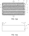
- FIG. 1( a ) and FIG. 1( b ) are a top view and a side view of a laminated battery according to an embodiment of the disclosure.
- FIG. 2 is a view showing the positive electrode sheet which is a component of the laminated battery according to an embodiment of the disclosure.
- FIG. 3 is a view showing the negative electrode sheet which is a component of the laminated battery according to an embodiment of the disclosure.
- FIG. 4 is a view showing the solid electrolyte sheet which is a component of the laminated battery according to an embodiment of the disclosure.
- FIG. 5( a ) and FIG. 5( b ) are a view showing a manufacturing process of the laminated battery of the disclosure.
- FIG. 6( a ) and FIG. 6( b ) are respectively a view showing an example of the disposition relationship between the positive electrode structure and the solid electrolyte sheet.
- the laminated battery of the disclosure can realize a laminated structure in which the electrode composite material portions are not displaced, the manufacturing process can be simplified. Moreover, even in the case where a sufficient lamination press pressure and confining pressure are applied, buckling, short circuits, and even drop-off of the electrode composite material can be suppressed, and as a result, the production yield can be improved.
- the laminated battery that can improve the adhesion of the laminated interfaces, has improved energy density and power density, and also has a long life can be realized.
- a laminated battery of the disclosure includes a positive electrode sheet and a negative electrode sheet.
- the positive electrode sheet alternately has positive electrode composite material coated portions and positive electrode composite material uncoated portions on at least one surface of a positive electrode current collector, wherein in the positive electrode composite material coated portions, a positive electrode composite material is laminated, and in the positive electrode composite material uncoated portions, the positive electrode composite material is not laminated; the positive electrode sheet is folded in a manner of mountain folds and valley folds alternated to form a comb-shaped positive electrode structure having a plurality of positive electrode portion laminates in which the adjacent positive electrode composite material coated portions are disposed on both outer layers, a plurality of positive electrode opening portions formed between the adjacent positive electrode portion laminates, and positive electrode portion laminate connecting portions for connecting the adjacent positive electrode portion laminates.
- the negative electrode sheet is folded in a manner of mountain folds and valley folds alternated to form a comb-shaped negative electrode structure having a plurality of negative electrode portion laminates, a plurality of negative electrode opening portions formed between the adjacent negative electrode portion laminates, and negative electrode portion laminate connecting portions for connecting the adjacent negative electrode portion laminates.
- the negative electrode portion laminates of the negative electrode structure are inserted into the positive electrode opening portions of the positive electrode structure, and the positive electrode portion laminates of the positive electrode structure are inserted into the negative electrode opening portions of the negative electrode structure to form a laminate in which the positive electrode structure and the negative electrode structure are fitted.
- the type of the laminated battery of the disclosure is not particularly limited. It may be a liquid battery including a liquid electrolyte or a solid battery including a solid or gel electrolyte. Further, in the case where it is a battery including a solid or gel electrolyte, the electrolyte may be organic or inorganic.
- FIG. 1( a ) is a top view of a laminated battery 10 of the disclosure
- FIG. 1( b ) is a side view thereof.
- the laminated battery 10 shown in FIG. 1 includes a positive electrode sheet 1 , a negative electrode sheet 4 , and a solid electrolyte sheet 7 as its components.
- the positive electrode sheet 1 has, on a positive electrode current collector, positive electrode composite material coated portions 2 in which positive electrode composite material layers are laminated, and positive electrode composite material uncoated portions 3 without the positive electrode composite material layers. Then, the positive electrode sheet 1 is folded so that mountain folds and valley folds alternate to form a comb-shaped positive electrode structure having a plurality of positive electrode portion laminates in which the adjacent positive electrode composite material coated portions 2 are disposed on both outer layers, a plurality of positive electrode opening portions formed between the adjacent positive electrode portion laminates, and positive electrode portion laminate connecting portions for connecting the adjacent positive electrode portion laminates. In addition, the positive electrode composite material uncoated portions 3 are disposed in the positive electrode portion laminate connecting portions.
- FIG. 5( a ) shows a comb-shaped positive electrode structure configuring the laminated battery 10 .
- the positive electrode structure of FIG. 5( a ) is in a comb shape in which the positive electrode sheet 1 is folded so that mountain folds and valley folds alternate and which has the plurality of positive electrode portion laminates in which the adjacent positive electrode composite material coated portions 2 are disposed on both outer layers, the plurality of positive electrode opening portions formed between the adjacent positive electrode portion laminates, and the positive electrode portion laminate connecting portions for connecting the adjacent positive electrode portion laminates.
- the positive electrode composite material uncoated portions 3 of the positive electrode sheet 1 are disposed in the positive electrode portion laminate connecting portions (indicated by b in FIG. 5( a ) ) and mountain fold portions (indicated by a in FIG. 5( a ) ) of the positive electrode portion laminates.
- the negative electrode sheet 4 has, on a negative electrode current collector, negative electrode composite material coated portions 5 in which negative electrode composite material layers are laminated, and negative electrode composite material uncoated portions 6 without the negative electrode composite material layers. Then, the negative electrode sheet 4 is folded so that mountain folds and valley folds alternate to form a comb-shaped negative electrode structure having the plurality of negative electrode portion laminates in which the adjacent negative electrode composite material coated portions 5 are disposed on both outer layers, the plurality of negative electrode opening portions formed between the adjacent negative electrode portion laminates, and the negative electrode portion laminate connecting portions for connecting the adjacent negative electrode portion laminates. In addition, the negative electrode composite material uncoated portions 6 are disposed in the negative electrode portion laminate connecting portions.
- FIG. 5( b ) shows the comb-shaped negative electrode structure configuring the laminated battery 10 .
- the negative electrode structure of FIG. 5( b ) is in a comb shape in which the negative electrode sheet 4 is folded so that mountain folds and valley folds alternate and which has the plurality of negative electrode portion laminates in which the adjacent negative electrode composite material coated portions 5 are disposed on both outer layers, the plurality of negative electrode opening portions formed between the adjacent negative electrode portion laminates, and the negative electrode portion laminate connecting portions for connecting the adjacent negative electrode portion laminates. Further, the negative electrode composite material uncoated portions 6 of the negative electrode sheet 4 are disposed in the negative electrode portion laminate connecting portions and mountain fold portions of the negative electrode portion laminates.
- the negative electrode portion laminates of the negative electrode structure ( FIG. 5( b ) ) are inserted into the positive electrode opening portions of the positive electrode structure ( FIG. 5( a ) ), and the positive electrode portion laminates of the positive electrode structure are inserted into the negative electrode opening portions of the negative electrode structure, and the solid electrolyte sheet 7 is disposed in a zigzag shape at the boundary between the positive electrode portion laminates and the negative electrode portion laminates.
- the laminated battery of the disclosure is characterized in that the positive electrode structure and the negative electrode structure in comb shapes are respectively produced with the electrode composite material layers positioned in advance, and these are fitted to form a laminate serving as a battery.
- the manufacturing process can be simplified, and at the same time, the laminated structure in which the electrode composite material portions are not displaced can be realized, and the production yield can be improved.
- the arrows shown in FIG. 1 are the directions of the lamination press applied to the laminated battery 10 .
- a solid battery requires press molding at a high surface pressure in a state in which a laminate serving as the battery is formed.
- the required pressing is applied from the arrow directions which are the lamination directions of the positive electrode portion laminates and the negative electrode portion laminates.
- the outermost layer of the laminated battery of the disclosure is a solid electrolyte sheet, and that the negative electrode portion laminates are disposed on the inner side of the solid electrolyte sheet.
- the outermost layer is the solid electrolyte sheet 7 ; specifically, the battery laminate, which is a fitting body of the positive electrode structure and the negative electrode structure, is covered with end portions of the solid electrolyte sheet 7 inserted in a zigzag shape. Further, the negative electrode portion laminates are disposed on the inner side of the solid electrolyte sheet 7 serving as the outermost layer of the laminated battery 10 .
- the positive electrode sheet which is a component of the laminated battery of the disclosure, is a configuration in which the positive electrode composite material layers are laminated on at least one surface of the positive electrode current collector.
- the positive electrode composite material layers of the positive electrode sheet used in the disclosure are characterized in that they are not formed on the entire surface of the positive electrode current collector but are formed discontinuously.
- the positive electrode sheet which is a component of the laminated battery of the disclosure, has, on the positive electrode current collector, the positive electrode composite material coated portions in which the positive electrode composite material is laminated and the positive electrode composite material uncoated portions in which the positive electrode composite material is not laminated.
- the positive electrode sheet may be any configuration as long as the positive electrode composite material layers are laminated on at least one surface of the positive electrode current collector, and depending on the type of the positive electrode current collector, the positive electrode composite material layers may be laminated on both surfaces of the positive electrode current collector.
- FIG. 2 is a view showing an embodiment of the positive electrode sheet which is a component of the laminated battery of the disclosure.
- the positive electrode sheet 1 has, on the positive electrode current collector, the positive electrode composite material coated portions 2 in which the positive electrode composite material is laminated, and the positive electrode composite material uncoated portions 3 in which the positive electrode composite material is not laminated; and the positive electrode composite material coated portions 2 and the positive electrode composite material uncoated portions 3 are alternately formed.
- the positive electrode current collector configuring the positive electrode sheet which is a component of the laminated battery of the disclosure, is not particularly limited, and a positive electrode current collector known as a positive electrode current collector of a lithium ion secondary battery can be applied.
- the material of the positive electrode current collector may be, for example, metal materials such as SUS, Ni, Cr, Au, Pt, Al, Fe, Ti, Zn, Cu and the like.
- the shape of the positive electrode current collector may be, for example, a foil shape, a plate shape, a mesh shape, a non-woven fabric shape, a foam shape or the like.
- carbon and the like may be disposed on the surface of the positive electrode current collector, and the surface may be roughened.
- the thickness thereof is not particularly limited either, and can be appropriately selected according to the needs.
- the electrode composite material to be laminated on the positive electrode current collector is not particularly limited, and a known composite material that can be used when a battery is produced can be applied.
- the positive electrode composite material contains at least a positive electrode active material, and may further contain a solid electrolyte, a conductive assistant, a binder and the like.
- the positive electrode active material is not particularly limited as long as it can store and release lithium ions, and may be, for example, LiCoO 2 , LiCoO 4 , LiMn 2 O 4 , LiNiO 2 , LiFePO 4 , lithium sulfide, sulfur or the like.
- the positive electrode sheet which is a component of the laminated battery of the disclosure
- the positive electrode composite material layers are discontinuously formed on the positive electrode current collector.
- the positive electrode sheet has the positive electrode composite material coated portions in which the positive electrode composite material is laminated, and the positive electrode composite material uncoated portions in which the positive electrode composite material is not laminated.
- the positive electrode sheet is folded so that mountain folds and valley folds alternate, so that the positive electrode composite material coated portions are laminated, to form the plurality of positive electrode portion laminates in which the adjacent positive electrode composite material coated portions are disposed on both outer layers, so as to form the positive electrode structure.
- the positive electrode structure has the plurality of positive electrode opening portions formed between the adjacent positive electrode portion laminates and the positive electrode portion laminate connecting portions for connecting the adjacent positive electrode portion laminates, and that the positive electrode composite material uncoated portions are disposed in the positive electrode portion laminate connecting portions.
- the positive electrode composite material is not present in the positive electrode portion laminate connecting portions and the positive electrode opening portions. For this reason, for example, even in a case where the negative electrode composite material layers are disposed in the peripheral region of the positive electrode portion laminate connecting portions at the end portions of the battery laminate, the function of a battery is not exhibited.
- the positive electrode composite material coated portions 2 and the positive electrode composite material uncoated portions 3 are alternately formed, and a and b in the figure show the distances between each of the positive electrode composite material coated portions 2 .
- FIG. 5( a ) shows the comb-shaped positive electrode structure configuring the laminated battery 10 shown in FIG. 1 and formed from the positive electrode sheet 1 shown in FIG. 2 .
- the positive electrode structure of FIG. 5( a ) is a structure in a comb shape in which the positive electrode sheet 1 is folded so that mountain folds and valley folds alternate and which has the plurality of positive electrode portion laminates in which the adjacent positive electrode composite material coated portions 2 are disposed on both outer layers, the plurality of positive electrode opening portions formed between the adjacent positive electrode portion laminates, and the positive electrode portion laminate connecting portions for connecting the adjacent positive electrode portion laminates.
- the positive electrode composite material uncoated portions 3 of the positive electrode sheet 1 are disposed in the positive electrode portion laminate connecting portions (indicated by b in FIG. 5( a ) ) and the mountain fold portions (indicated by a in FIG. 5( a ) ) of the positive electrode portion laminates.
- the positive electrode composite material uncoated portions in the positive electrode sheet are disposed at one of the two ends (a and b in FIG. 5( a ) ) of the positive electrode structure by every other one, and form the positive electrode portion laminate connecting portions (b in FIG. 5( a ) ) by every other one.
- the size of the positive electrode composite material coated portions and the distances between each of the positive electrode composite material coated portions can be appropriately set according to the size and the like of the battery to be configured.
- the distances between the positive electrode composite material uncoated portions serving as the positive electrode portion laminate connecting portions can be appropriately set depending on the thickness of the negative electrode structure or the like to be fitted with the positive electrode structure. That is, a battery laminate having a desired thickness and a desired size can be formed by making the distances between the positive electrode composite material coated portions different from each other by every other one (a and b in FIG. 2 ).
- the positive electrode sheet used in the disclosure may have a solid electrolyte layer on the surface.
- the solid electrolyte layer may be disposed so as to cover at least the positive electrode composite material coated portions.
- any capable of lithium ion conduction between the positive electrode and the negative electrode may be used as a solid electrolyte disposed on the positive electrode composite material coated portions, and may be, for example, oxide electrolytes, sulfide electrolytes, inorganic solid electrolytes such as lithium-containing salts, polymer-based solid electrolytes such as polyethylene oxide, gel-based solid electrolytes containing lithium-containing salts or lithium ion conductive ionic liquids, or the like.
- the solid electrolyte may include a binder and the like according to the needs.
- the negative electrode sheet which is a component of the laminated battery of the disclosure, is not particularly limited as long as it has a function of performing current collection of a negative electrode active material layer.
- a negative electrode active material is not particularly limited as long as it can store and release lithium ions, and may be, for example, metallic lithium, lithium alloys, metal oxides, metal sulfides, metal nitrides, silicon oxides, silicon, carbon materials such as graphite, or the like.
- the negative electrode sheet used in the laminated battery of the disclosure is a sheet made of the negative electrode active material itself.
- the laminated battery of the disclosure can be manufactured without considering the disposition of the negative electrode composite material.
- the negative electrode sheet is the sheet made of the negative electrode active material itself
- the negative electrode active material is present at the end portions of the obtained laminated battery; however, since the positive electrode active material is not present in the peripheral region of the positive electrode portion laminate connecting portions and the positive electrode opening portions, which are the end portions of the formed battery laminate, the end portions do not exhibit the function as a battery.
- the negative electrode sheet used in the laminated battery of the disclosure may be a configuration in which the negative electrode composite material layers are formed on at least one surface of the negative electrode current collector.
- the negative electrode composite material layers may be formed on the entire surface of the negative electrode current collector or may be formed discontinuously as in the case of the positive electrode sheet.
- the negative electrode composite material layers are formed on the negative electrode current collector, it may be any configuration as long as the negative electrode composite material layers are laminated on at least one surface and, depending on the type of the negative electrode current collector, may be laminated on both surfaces of the negative electrode current collector.
- the negative electrode composite material layers are discontinuously formed on the negative electrode current collector, it is preferable to alternately have the negative electrode composite material coated portions in which the negative electrode composite material is laminated, and the negative electrode composite material uncoated portions in which the negative electrode composite material is not laminated. Then, when the negative electrode structure formed from the negative electrode sheet is fitted with the positive electrode structure, it is preferable to adjust so that the negative electrode composite material coated portions are laminated and disposed on the positive electrode composite material coated portions, and that the negative electrode composite material uncoated portions are disposed in the negative electrode portion laminate connecting portions.
- the negative electrode composite material coated portions 5 and the negative electrode composite material uncoated portions 6 are alternately formed.
- FIG. 5( b ) shows the comb-shaped negative electrode structure configuring the laminated battery 10 shown in FIG. 1 and formed from the negative electrode sheet 4 shown in FIG. 3 .
- the negative electrode structure of FIG. 5( b ) is a structure in a comb shape in which the negative electrode sheet 4 is folded so that mountain folds and valley folds alternate and which has the plurality of negative electrode portion laminates in which the adjacent negative electrode composite material coated portions 5 are disposed on both outer layers, the plurality of negative electrode opening portions formed between the adjacent negative electrode portion laminates, and the negative electrode portion laminate connecting portions for connecting the adjacent negative electrode portion laminates. Further, the negative electrode composite material uncoated portions 6 of the negative electrode sheet 4 are disposed in the negative electrode portion laminate connecting portions and the mountain fold portions of the negative electrode portion laminates.
- the negative electrode composite material uncoated portions in the negative electrode sheet are disposed at one of the two ends of the negative electrode structure by every other one, and form the negative electrode portion laminate connecting portions by every other one.
- the size of the negative electrode composite material coated portions and the distances between each of the negative electrode composite material coated portions can be appropriately set according to the size and the like of the battery to be configured.
- the distances between the negative electrode composite material uncoated portions serving as the negative electrode portion laminate connecting portions can be appropriately set depending on the thickness of the positive electrode structure or the like to be fitted with the negative electrode structure. That is, a battery laminate having a desired thickness and a desired size can be formed by making the distances between the negative electrode composite material coated portions different from each other by every other one.
- the negative electrode current collector is not particularly limited, and a known negative electrode current collector can be applied.
- the material of the negative electrode current collector may be, for example, Cu, SUS, Ni, Ti or the like, and the shape of the negative electrode current collector may be, for example, a foil shape, a plate shape, a mesh shape, a non-woven fabric shape, a foam shape or the like.
- carbon and the like may be disposed on the surface of the negative electrode current collector, and the surface may be roughened.
- the thickness of the negative electrode current collector is not particularly limited either, and can be appropriately selected according to the needs.
- the negative electrode composite material is not particularly limited, and a known composite material that can be used when a battery is produced can be applied.
- the negative electrode composite material contains at least the negative electrode active material, and may further contain a solid electrolyte, a conductive assistant, a binder and the like according to the needs.
- the area of the negative electrode composite material coated portions is greater than or equal to the area of the positive electrode composite material coated portions of the positive electrode sheet.
- the positive electrode composite material coated portions are smaller than the negative electrode composite material coated portions, by the press after laminating and disposing these to form the battery laminate, the positive electrode composite material coated portions are buried in the inner side of the negative electrode composite material coated portions, and cracking may occur at the end portions of the negative electrode composite material coated portions.
- electrocrystallization can be avoided by setting the area of the negative electrode composite material coated portions to be equal to or greater than the area of the positive electrode composite material coated portions of the positive electrode sheet.
- the area of the negative electrode composite material coated portions and the area of the positive electrode composite material coated portions are equal. If the areas are equal, the pressure of the lamination press can be uniformly applied, and the resistance value can be reduced.
- the negative electrode sheet used in the disclosure may have a solid electrolyte layer on the surface.
- the solid electrolyte layer may be disposed so as to cover at least the negative electrode composite material coated portions.
- the solid electrolyte layer may be laminated on the entire negative electrode sheet.
- the solid electrolyte may be the same as or different from the above-described one used in the positive electrode sheet. Anything capable of lithium ion conduction between the positive electrode and the negative electrode may be used, and may be, for example, oxide electrolytes, sulfide electrolytes, inorganic solid electrolytes such as lithium-containing salts, polymer-based solid electrolytes such as polyethylene oxide, gel-based solid electrolytes containing lithium-containing salts or lithium ion conductive ionic liquids, or the like.
- the solid electrolyte may include a binder and the like according to the needs.
- a solid electrolyte sheet may be used as an optional component.
- the solid electrolyte sheet is disposed between the positive electrode portion laminates and the negative electrode portion laminates.
- the laminated battery of the disclosure can be configured without using the solid electrolyte sheet.
- the solid electrolyte sheet used in the disclosure is not particularly limited, and may be, for example, a dense sheet comprising an inorganic solid electrolyte and a binder, a composite sheet made by embedding a solid electrolyte in a porous sheet such as a non-woven fabric configured by polypropylene, cellulose, glass and the like, or an organic solid electrolyte sheet, or the like.
- the solid electrolyte used in the solid electrolyte sheet may be, for example, oxide electrolytes, sulfide electrolytes, inorganic solid electrolytes such as lithium-containing salts, polymer-based solid electrolytes such as polyethylene oxide, gel-based solid electrolytes containing lithium-containing salts or lithium ion conductive ionic liquids, or the like.
- the solid electrolyte may include a binder and the like according to the needs.
- the composition ratio of each substance contained in the solid electrolyte is not particularly limited as long as the battery can operate properly.
- the disposition of the solid electrolyte sheet may be, for example, an aspect in which it is disposed in a zigzag shape at the boundary between the positive electrode portion laminates and the negative electrode portion laminates.
- FIG. 4 shows the solid electrolyte sheet 7 which configures the laminated battery 10 shown in FIG. 1 .
- the negative electrode portion laminates of the negative electrode structure are inserted into the positive electrode opening portions of the positive electrode structure, and the positive electrode portion laminates of the positive electrode structure are inserted into the negative electrode opening portions of the negative electrode structure, and the solid electrolyte sheet 7 is disposed in a zigzag shape at the boundary between the positive electrode portion laminates and the negative electrode portion laminates.
- FIG. 6 shows an example of the disposition relationship between the positive electrode structure and the solid electrolyte sheet.
- FIG. 6( a ) is a view showing the disposition relationship between the positive electrode structure and the solid electrolyte sheet 7 which is an embodiment for obtaining the laminated battery 10 shown in FIG. 1 .
- the solid electrolyte sheet 7 is disposed in zigzag shape along the front and back surfaces of the positive electrode portion laminates of the positive electrode structure.
- the laminated battery 10 shown in FIG. 1 can be formed, for example, by inserting and fitting the positive electrode portion laminates into the negative electrode opening portions of the negative electrode structure in a state where the solid electrolyte sheet 7 is disposed on the positive electrode portion laminates as shown in FIG. 6( a ) .
- the laminated battery of the disclosure for the purpose of improving the safety, it is preferable that a solid electrolyte sheet having a sufficient length is used, and the outer periphery of the laminated battery is covered with the end portions of the solid electrolyte sheet so that the outermost layer is the solid electrolyte sheet. In addition, it is preferable to dispose the negative electrode portion laminates on the inner side of the solid electrolyte sheet.
- the outermost layer of the laminated battery 10 shown in FIG. 1 is the solid electrolyte sheet 7 ; specifically, the battery laminate, which is a fitting body of the positive electrode structure and the negative electrode structure, is covered with the end portions of the solid electrolyte sheet 7 inserted in a zigzag shape. Further, the negative electrode portion laminates are disposed on the inner side of the solid electrolyte sheet 7 serving as the outermost layer of the laminated battery 10 .
- solid electrolyte sheet includes, for example, an aspect in which a bag having opening portions is formed by the solid electrolyte sheet, and at least one of the positive electrode portion laminates and the negative electrode portion laminates is inserted from the opening portions, and the solid electrolyte sheet is disposed to cover the front and back surfaces of the portion laminates, and the solid electrolyte sheet is not disposed on the portion laminate connecting portions.
- FIG. 6( b ) shows an embodiment in which the solid electrolyte sheet is disposed in a bag shape.
- the positive electrode portion laminates are inserted from the opening portions of the bag formed by the solid electrolyte sheet 7 , and the solid electrolyte sheet 7 is disposed along the front and back surfaces of the positive electrode portion laminates. Further, the solid electrolyte sheet 7 is not disposed on the positive electrode portion laminate connecting portions.
- the laminated battery can be formed by inserting and fitting the positive electrode portion laminates into the negative electrode opening portions of the negative electrode structure in a state where the solid electrolyte sheet 7 is disposed on the positive electrode portion laminates as shown in FIG. 6( b ) .
- a separator may be used as an optional component.
- the separator is disposed between the positive electrode portion laminates and the negative electrode portion laminates.
- the separator used in the laminated battery of the disclosure is not particularly limited as long as it can be impregnated with an electrolyte solution and the like, and a separator known as a separator of a lithium ion secondary battery can be applied.
- a separator known as a separator of a lithium ion secondary battery can be applied.
- a porous sheet such as a non-woven fabric, a porous film and the like may be used.
- the material of the separator is not particularly limited either, and may be, for example, polypropylene, polyethylene, polyethylene terephthalate, polybutylene terephthalate, ethylene-propylene copolymer, cellulose, or the like.
- basis weight and thickness of the separator are not particularly limited either, and may be appropriately set according to the required performance and the like of the laminated battery.
- the laminated battery of the disclosure is a battery including a liquid electrolyte
- an electrolyte solution is used.
- the electrolyte solution used in the laminated battery of the disclosure is not particularly limited, and a known electrolyte solution used in a lithium ion secondary battery can be applied.
- ethylene carbonate, dimethyl carbonate, ethyl methyl carbonate, propylene carbonate or the like may be used, or a composite material thereof may be used as a solvent which configures the electrolyte solution.
- lithium-containing salts such as LiPF 6 , LiBF 4 , LiClO 4 and the like, or lithium-containing ionic liquids, such as LiTFSi and the like, may be used, or a composite material thereof may be used as an electrolyte which configures the electrolyte solution.
- the electrolyte solution may contain an additive and the like according to the needs.
- the laminated battery of the disclosure may optionally include other configurations for achieving the function as a battery.
- a positive electrode tab is connected to the positive electrode portion laminate connecting portions of the laminated battery of the disclosure, and that a negative electrode tab is connected to the negative electrode portion laminate connecting portions.
- a positive electrode tab is connected to the positive electrode portion laminate connecting portions of the laminated battery of the disclosure, and that a negative electrode tab is connected to the negative electrode portion laminate connecting portions.
- the package form of the laminated battery of the disclosure is not particularly limited.
- it may be enclosed in a metal can to form a can cell, or may be enclosed in a laminate sheet of aluminum or the like to form a laminate cell.
- the manufacturing method of the laminated battery of the disclosure is not particularly limited, and may be, for example, a method including a positive electrode sheet forming step, a positive electrode structure forming step, a negative electrode structure forming step, and a fitting step.
- the positive electrode sheet forming step is a step of forming the positive electrode sheet alternately having the positive electrode composite material coated portions and the positive electrode composite material uncoated portions on at least one surface of the positive electrode current collector, wherein in the positive electrode composite material coated portions, the positive electrode composite material is laminated by discontinuously coating the positive electrode composite material, and in the positive electrode composite material uncoated portions, the positive electrode composite material is not laminated.
- a method of discontinuously coating the positive electrode composite material is not particularly limited.
- it may be a method of forming a positive electrode composite material containing a positive electrode active material, coating the positive electrode composite material on the positive electrode current collector by discontinuous coating, and then performing drying and rolling.
- the solid electrolyte layer may be formed at least on the positive electrode composite material coated portions.
- the forming method of the solid electrolyte layer is not particularly limited, and a known method can be applied.
- the positive electrode structure forming step is a step of folding the positive electrode sheet obtained in the positive electrode sheet forming step so that mountain folds and valley folds alternate to form the comb-shaped positive electrode structure including the plurality of positive electrode portion laminates in which the adjacent positive electrode composite material coated portions are disposed on both outer layers, the plurality of positive electrode opening portions formed between the adjacent positive electrode portion laminates, and the positive electrode portion laminate connecting portions for connecting the adjacent positive electrode portion laminates.
- the means of folding the positive electrode sheet so that mountain folds and valley folds alternate and the method of forming the plurality of positive electrode portion laminates in which the adjacent positive electrode composite material coated portions are disposed on both outer layers are not particularly limited, as long as the positive electrode structure having the positive electrode portion laminates, the positive electrode opening portions, and the positive electrode portion laminate connecting portions can be formed.
- the positive electrode composite material uncoated portions are disposed in the positive electrode portion laminate connecting portions.
- the negative electrode structure forming step is a step of folding the negative electrode sheet so that mountain folds and valley folds alternate to form the comb-shaped negative electrode structure including the plurality of negative electrode portion laminates, the plurality of negative electrode opening portions formed between the adjacent negative electrode portion laminates, and the negative electrode portion laminate connecting portions for connecting the adjacent negative electrode portion laminates.
- the means of folding the negative electrode sheet so that mountain folds and valley folds alternate and the method of forming the plurality of negative electrode portion laminates are not particularly limited, as long as the negative electrode structure having the negative electrode portion laminates, the negative electrode opening portions, and the negative electrode portion laminate connecting portions can be formed.
- the negative electrode sheet may be configured by the sheet made of the negative electrode active material itself, or may be configured by the negative electrode composite material layers formed on at least one surface of the negative electrode current collector. In the case where it is configured by the negative electrode composite material layers formed on the negative electrode current collector, it is preferable that the area of the negative electrode composite material coated portions is greater than or equal to the area of the positive electrode composite material coated portions.
- the negative electrode composite material uncoated portions are disposed in the negative electrode portion laminate connecting portions.
- the plurality of negative electrode portion laminates it is preferable to form so that lamination displacement between the adjacent negative electrode composite material coated portions does not occur.
- a negative electrode sheet having a solid electrolyte layer on the surface may be used as the negative electrode sheet.
- the solid electrolyte layer may be disposed at least on the surface of the negative electrode composite material coated portions.
- the solid electrolyte layer may be laminated on the entire negative electrode sheet.
- the forming method of the solid electrolyte layer is not particularly limited, and a known method can be applied.
- the fitting step is a step of inserting the negative electrode portion laminates of the negative electrode structure obtained in the negative electrode structure forming step into the positive electrode opening portions of the positive electrode structure obtained in the positive electrode structure forming step, inserting the positive electrode portion laminates of the positive electrode structure into the negative electrode opening portions of the negative electrode structure, and fitting the positive electrode structure and the negative electrode structure to form the battery laminate.
- At least one of the solid electrolyte sheet and the separator may be disposed between the positive electrode portion laminates and the negative electrode portion laminates to form the battery laminate.
- the solid electrolyte sheet and the separator in order to improve the safety of the obtained battery, in the fitting step, it is desirable to dispose so that the outermost layer of the battery is the solid electrolyte sheet or the separator. For this reason, it is preferable to use the solid electrolyte sheet or the separator having a sufficient length to cover the outer periphery of the laminated battery with its end portions. In addition, it is preferable to dispose the negative electrode portion laminates on the inner side of the solid electrolyte sheet or the separator.
- the manufacturing method of the laminated battery of the disclosure is characterized in respectively producing the positive electrode structure and the negative electrode structure in comb shapes with the electrode composite material layers positioned in advance, and fitting these to form the laminate serving as a battery.
- the manufacturing process can be simplified, and at the same time, the laminated structure in which the electrode composite material portions are not displaced can be realized, and the production yield can be improved.
- the fitting step it is preferable to adjust so that the negative electrode composite material coated portions are laminated and disposed on the positive electrode composite material coated portions.
- FIG. 5 shows a schematic view of the fitting step.
- FIG. 5( a ) shows the comb-shaped positive electrode structure
- FIG. 5( b ) shows the comb-shaped negative electrode structure.
- the battery laminate is formed by inserting the negative electrode portion laminates of the negative electrode structure of FIG. 5( b ) into the positive electrode opening portions of the positive electrode structure of FIG. 5( a ) , inserting the positive electrode portion laminates of the positive electrode structure of FIG. 5( a ) into the negative electrode opening portions of the negative electrode structure of FIG. 5( b ) , and fitting the positive electrode structure and the negative electrode structure.
- the fitting step in the case where one solid electrolyte sheet is used, in the fitting step, it may be, for example, an aspect in which the solid electrolyte sheet is disposed in a zigzag shape at the boundary between the positive electrode portion laminates and the negative electrode portion laminates.
- FIG. 6( a ) shows an embodiment of the positive electrode structure and the solid electrolyte sheet for obtaining the laminated battery 10 shown in FIG. 1 .
- the solid electrolyte sheet 7 is disposed in zigzag shape along the front and back surfaces of the positive electrode portion laminates of the positive electrode structure.
- the battery laminate is formed by using the positive electrode structure in which the solid electrolyte sheet 7 is disposed on the positive electrode portion laminates as shown in FIG. 6( a ) , and inserting and fitting the positive electrode portion laminates into the negative electrode opening portions of the negative electrode structure.
- a fitting step for example, it may be an example of using an electrode structure in a state in which a bag having opening portions is formed by the solid electrolyte sheet, and at least one of the positive electrode portion laminates and the negative electrode portion laminates is inserted from the opening portions, and the solid electrolyte sheet is disposed to cover the front and back surfaces of the electrode portion laminates, and the solid electrolyte sheet is not disposed on the electrode portion laminate connecting portions.
- FIG. 6( b ) a fitting step in the case of using the electrode structure which has disposed the solid electrolyte sheet in a bag shape is described.
- the positive electrode portion laminates are inserted from the opening portions of the bag formed by the solid electrolyte sheet 7 , and the solid electrolyte sheet 7 is disposed along the front and back surfaces of the positive electrode portion laminates. Further, the solid electrolyte sheet 7 is not disposed on the positive electrode portion laminate connecting portions.
- the battery laminate is formed by using the positive electrode structure which has disposed the solid electrolyte sheet 7 as shown in FIG. 6( b ) , and inserting and fitting the positive electrode portion laminates into the negative electrode opening portions of the negative electrode structure.
- a pressing step which applies a pressure to the lamination directions of the obtained battery laminate may be further performed.
- a solid battery requires press molding at a high surface pressure in a state in which a laminate serving as the battery is formed.
- FIG. 1 shows the directions of the lamination press to be applied to the laminated battery 10 as the arrows.
- the required pressing is applied from the arrow directions, which are the lamination directions of the positive electrode portion laminates and the negative electrode portion laminates, to sandwich the battery laminate.
Landscapes
- Chemical & Material Sciences (AREA)
- Engineering & Computer Science (AREA)
- Chemical Kinetics & Catalysis (AREA)
- Electrochemistry (AREA)
- General Chemical & Material Sciences (AREA)
- Manufacturing & Machinery (AREA)
- Materials Engineering (AREA)
- Secondary Cells (AREA)
- Battery Electrode And Active Subsutance (AREA)
- Connection Of Batteries Or Terminals (AREA)
Abstract
Description
- [Patent Document 1] Japanese Laid-open No. 2000-106154
- [Patent Document 2] Japanese Laid-open No. 2015-118870
Claims (16)
Applications Claiming Priority (3)
| Application Number | Priority Date | Filing Date | Title |
|---|---|---|---|
| JPJP2018-233431 | 2018-12-13 | ||
| JP2018-233431 | 2018-12-13 | ||
| JP2018233431A JP7041048B2 (en) | 2018-12-13 | 2018-12-13 | Manufacturing method of laminated battery and laminated battery |
Publications (2)
| Publication Number | Publication Date |
|---|---|
| US20200194839A1 US20200194839A1 (en) | 2020-06-18 |
| US11515568B2 true US11515568B2 (en) | 2022-11-29 |
Family
ID=71070982
Family Applications (1)
| Application Number | Title | Priority Date | Filing Date |
|---|---|---|---|
| US16/711,437 Active 2040-07-21 US11515568B2 (en) | 2018-12-13 | 2019-12-12 | Laminated battery and manufacturing method of laminated battery |
Country Status (3)
| Country | Link |
|---|---|
| US (1) | US11515568B2 (en) |
| JP (1) | JP7041048B2 (en) |
| CN (1) | CN111326707B (en) |
Families Citing this family (5)
| Publication number | Priority date | Publication date | Assignee | Title |
|---|---|---|---|---|
| CN111863982A (en) * | 2020-07-31 | 2020-10-30 | 广东凯金新能源科技股份有限公司 | A kind of porous carbon negative electrode battery sheet and preparation method thereof |
| JP7611729B2 (en) * | 2021-02-26 | 2025-01-10 | 本田技研工業株式会社 | Pouch Cell |
| EP4152434A1 (en) * | 2021-09-17 | 2023-03-22 | VARTA Microbattery GmbH | Energy storage element |
| US20240258650A1 (en) * | 2021-12-06 | 2024-08-01 | Lg Energy Solution, Ltd. | Electrode Assembly, Manufacturing Method Thereof And Battery Cell Including The Same |
| CN117712461A (en) * | 2022-09-06 | 2024-03-15 | 通用汽车环球科技运作有限责任公司 | Sulfide-based solid state battery pack manufactured by high-speed zigzag stacking |
Citations (14)
| Publication number | Priority date | Publication date | Assignee | Title |
|---|---|---|---|---|
| JPS5650066A (en) | 1979-09-28 | 1981-05-07 | Yuasa Battery Co Ltd | Manufacture of conductive grid for storage battery |
| JPH031455A (en) | 1989-05-30 | 1991-01-08 | Shin Kobe Electric Mach Co Ltd | Sealed square alkaline storage battery |
| JP2000082495A (en) | 1998-09-04 | 2000-03-21 | Sony Corp | Solid electrolyte battery |
| JP2000106154A (en) | 1998-09-28 | 2000-04-11 | Matsushita Electric Ind Co Ltd | All-solid-state battery and its manufacturing method |
| US20030082446A1 (en) * | 2000-10-20 | 2003-05-01 | Yet-Ming Chiang | Reticulated and controlled porosity battery structures |
| CN1776939A (en) | 2004-11-18 | 2006-05-24 | 索尼株式会社 | Battery |
| CN101461087A (en) | 2006-05-23 | 2009-06-17 | Iom技术公司 | All-solid-state secondary battery |
| CN102473903A (en) | 2009-07-14 | 2012-05-23 | 川崎重工业株式会社 | Fiber electrode, fiber battery and manufacturing method thereof, fiber electrode and fiber battery manufacturing equipment |
| CN202396078U (en) | 2010-09-01 | 2012-08-22 | 日产自动车株式会社 | Wiring substrate, cell stack and ambipolar secondary cell |
| US20120288747A1 (en) * | 2010-01-29 | 2012-11-15 | Jsr Corporation | Electrochemical device |
| JP2013219057A (en) | 2006-05-15 | 2013-10-24 | Lg Chem Ltd | Electrolyte assembly for secondary battery with novel lamination structure |
| CN104584274A (en) | 2012-09-05 | 2015-04-29 | 罗伯特·博世有限公司 | Electrical energy storage cell, electrical energy storage module and method for producing an electrical energy storage cell |
| JP2015118870A (en) | 2013-12-19 | 2015-06-25 | トヨタ自動車株式会社 | Manufacturing method of all solid state battery |
| US20170222244A1 (en) * | 2016-02-03 | 2017-08-03 | Samsung Electronics Co., Ltd. | Solid electrolyte and lithium battery comprising the solid electrolyte |
Family Cites Families (1)
| Publication number | Priority date | Publication date | Assignee | Title |
|---|---|---|---|---|
| JPS5650066U (en) * | 1979-09-25 | 1981-05-02 |
-
2018
- 2018-12-13 JP JP2018233431A patent/JP7041048B2/en active Active
-
2019
- 2019-09-29 CN CN201910934454.9A patent/CN111326707B/en active Active
- 2019-12-12 US US16/711,437 patent/US11515568B2/en active Active
Patent Citations (16)
| Publication number | Priority date | Publication date | Assignee | Title |
|---|---|---|---|---|
| JPS5650066A (en) | 1979-09-28 | 1981-05-07 | Yuasa Battery Co Ltd | Manufacture of conductive grid for storage battery |
| JPH031455A (en) | 1989-05-30 | 1991-01-08 | Shin Kobe Electric Mach Co Ltd | Sealed square alkaline storage battery |
| JP2000082495A (en) | 1998-09-04 | 2000-03-21 | Sony Corp | Solid electrolyte battery |
| JP2000106154A (en) | 1998-09-28 | 2000-04-11 | Matsushita Electric Ind Co Ltd | All-solid-state battery and its manufacturing method |
| US20030082446A1 (en) * | 2000-10-20 | 2003-05-01 | Yet-Ming Chiang | Reticulated and controlled porosity battery structures |
| CN1776939A (en) | 2004-11-18 | 2006-05-24 | 索尼株式会社 | Battery |
| JP2006147300A (en) | 2004-11-18 | 2006-06-08 | Sony Corp | battery |
| JP2013219057A (en) | 2006-05-15 | 2013-10-24 | Lg Chem Ltd | Electrolyte assembly for secondary battery with novel lamination structure |
| CN101461087A (en) | 2006-05-23 | 2009-06-17 | Iom技术公司 | All-solid-state secondary battery |
| CN102473903A (en) | 2009-07-14 | 2012-05-23 | 川崎重工业株式会社 | Fiber electrode, fiber battery and manufacturing method thereof, fiber electrode and fiber battery manufacturing equipment |
| US20120288747A1 (en) * | 2010-01-29 | 2012-11-15 | Jsr Corporation | Electrochemical device |
| CN202396078U (en) | 2010-09-01 | 2012-08-22 | 日产自动车株式会社 | Wiring substrate, cell stack and ambipolar secondary cell |
| CN104584274A (en) | 2012-09-05 | 2015-04-29 | 罗伯特·博世有限公司 | Electrical energy storage cell, electrical energy storage module and method for producing an electrical energy storage cell |
| JP2015118870A (en) | 2013-12-19 | 2015-06-25 | トヨタ自動車株式会社 | Manufacturing method of all solid state battery |
| US20170222244A1 (en) * | 2016-02-03 | 2017-08-03 | Samsung Electronics Co., Ltd. | Solid electrolyte and lithium battery comprising the solid electrolyte |
| CN107039680A (en) | 2016-02-03 | 2017-08-11 | 三星电子株式会社 | Solid electrolyte and lithium battery including said solid electrolyte |
Non-Patent Citations (2)
| Title |
|---|
| "Office Action of China Counterpart Application" with English translation thereof, dated Aug. 22, 2022, p. 1-p. 21. |
| "Office Action of Japan Counterpart Application" with English translation thereof, dated Oct. 5, 2021, p. 1-p. 8. |
Also Published As
| Publication number | Publication date |
|---|---|
| CN111326707B (en) | 2023-05-05 |
| CN111326707A (en) | 2020-06-23 |
| JP2020095871A (en) | 2020-06-18 |
| US20200194839A1 (en) | 2020-06-18 |
| JP7041048B2 (en) | 2022-03-23 |
Similar Documents
| Publication | Publication Date | Title |
|---|---|---|
| US11515568B2 (en) | Laminated battery and manufacturing method of laminated battery | |
| JP6567491B2 (en) | Electrochemical cell having folded electrodes and separator, battery comprising the cell, and method of forming the same | |
| US11545699B2 (en) | Solid state battery and solid state battery manufacturing method | |
| EP3252862A1 (en) | Secondary battery | |
| JP3758629B2 (en) | Laminate sheet and laminate battery using the same | |
| CN115986329A (en) | Electrode assembly, cylindrical battery cell, battery pack including same, and automobile | |
| KR101543055B1 (en) | Stack and Folding-Typed Electrode Assembly Having Improved Safety Property and Method for preparation of the same | |
| US9431680B2 (en) | Electric storage device, electric storage system, and manufacturing method thereof | |
| JP7253399B2 (en) | secondary battery | |
| JP2012212506A (en) | Laminate type battery | |
| KR101487092B1 (en) | Pouch for secondary battery and secondary battery using the same | |
| US20200203776A1 (en) | Wound battery and manufacturing method of wound battery | |
| US12542298B2 (en) | Electrode assembly and method for manufacturing the same | |
| JP2011198742A (en) | Laminated type battery | |
| JP7505700B2 (en) | Electrode assembly and manufacturing method thereof | |
| JP2010244865A (en) | Laminated battery | |
| JP2011129446A (en) | Laminated type battery | |
| KR101709391B1 (en) | Nonaqueous electrolyte secondary battery | |
| JP2011181310A (en) | Lamination-type unit cell | |
| JP6376441B2 (en) | Power storage device and method for manufacturing power storage device | |
| JP2011108538A (en) | Laminate battery | |
| JP2005129393A (en) | Secondary battery | |
| KR20160140507A (en) | Electrode assembly with directional thickness and Lithium secondary battery comprising the same | |
| KR102848105B1 (en) | Method for manufacturing an electrode assembly | |
| US20240297348A1 (en) | Solid battery and method for manufacturing solid battery |
Legal Events
| Date | Code | Title | Description |
|---|---|---|---|
| FEPP | Fee payment procedure |
Free format text: ENTITY STATUS SET TO UNDISCOUNTED (ORIGINAL EVENT CODE: BIG.); ENTITY STATUS OF PATENT OWNER: LARGE ENTITY |
|
| AS | Assignment |
Owner name: HONDA MOTOR CO.,LTD., JAPAN Free format text: ASSIGNMENT OF ASSIGNORS INTEREST;ASSIGNORS:SHIMIZU, WATARU;OHTA, MASAHIRO;SUKIGARA, TORU;SIGNING DATES FROM 20191212 TO 20191213;REEL/FRAME:051747/0203 |
|
| STPP | Information on status: patent application and granting procedure in general |
Free format text: DOCKETED NEW CASE - READY FOR EXAMINATION |
|
| STPP | Information on status: patent application and granting procedure in general |
Free format text: NON FINAL ACTION MAILED |
|
| STPP | Information on status: patent application and granting procedure in general |
Free format text: RESPONSE TO NON-FINAL OFFICE ACTION ENTERED AND FORWARDED TO EXAMINER |
|
| STPP | Information on status: patent application and granting procedure in general |
Free format text: NOTICE OF ALLOWANCE MAILED -- APPLICATION RECEIVED IN OFFICE OF PUBLICATIONS |
|
| STPP | Information on status: patent application and granting procedure in general |
Free format text: AWAITING TC RESP., ISSUE FEE NOT PAID |
|
| STPP | Information on status: patent application and granting procedure in general |
Free format text: NOTICE OF ALLOWANCE MAILED -- APPLICATION RECEIVED IN OFFICE OF PUBLICATIONS |
|
| STPP | Information on status: patent application and granting procedure in general |
Free format text: PUBLICATIONS -- ISSUE FEE PAYMENT VERIFIED |
|
| STCF | Information on status: patent grant |
Free format text: PATENTED CASE |