US11484960B2 - Dual wire welding or additive manufacturing contact tip and diffuser - Google Patents

Dual wire welding or additive manufacturing contact tip and diffuser Download PDF

Info

Publication number
US11484960B2
US11484960B2 US16/658,681 US201916658681A US11484960B2 US 11484960 B2 US11484960 B2 US 11484960B2 US 201916658681 A US201916658681 A US 201916658681A US 11484960 B2 US11484960 B2 US 11484960B2
Authority
US
United States
Prior art keywords
contact tip
welding
bore
wire electrode
diameter
Prior art date
Legal status (The legal status is an assumption and is not a legal conclusion. Google has not performed a legal analysis and makes no representation as to the accuracy of the status listed.)
Active, expires
Application number
US16/658,681
Other versions
US20200047275A1 (en
Inventor
Alexander J. Stergios
Steven R. Peters
Bruce J. Chantry
Matthew A. Weeks
Current Assignee (The listed assignees may be inaccurate. Google has not performed a legal analysis and makes no representation or warranty as to the accuracy of the list.)
Lincoln Global Inc
Original Assignee
Lincoln Global Inc
Priority date (The priority date is an assumption and is not a legal conclusion. Google has not performed a legal analysis and makes no representation as to the accuracy of the date listed.)
Filing date
Publication date
Priority claimed from US15/671,295 external-priority patent/US10792752B2/en
Application filed by Lincoln Global Inc filed Critical Lincoln Global Inc
Priority to US16/658,681 priority Critical patent/US11484960B2/en
Publication of US20200047275A1 publication Critical patent/US20200047275A1/en
Assigned to LINCOLN GLOBAL, INC. reassignment LINCOLN GLOBAL, INC. ASSIGNMENT OF ASSIGNORS INTEREST (SEE DOCUMENT FOR DETAILS). Assignors: WEEKS, Matthew A., CHANTRY, BRUCE J., PETERS, STEVEN R., STERGIOS, ALEXANDER J.
Application granted granted Critical
Publication of US11484960B2 publication Critical patent/US11484960B2/en
Active legal-status Critical Current
Adjusted expiration legal-status Critical

Links

Images

Classifications

    • BPERFORMING OPERATIONS; TRANSPORTING
    • B23MACHINE TOOLS; METAL-WORKING NOT OTHERWISE PROVIDED FOR
    • B23KSOLDERING OR UNSOLDERING; WELDING; CLADDING OR PLATING BY SOLDERING OR WELDING; CUTTING BY APPLYING HEAT LOCALLY, e.g. FLAME CUTTING; WORKING BY LASER BEAM
    • B23K9/00Arc welding or cutting
    • B23K9/24Features related to electrodes
    • B23K9/26Accessories for electrodes, e.g. ignition tips
    • BPERFORMING OPERATIONS; TRANSPORTING
    • B23MACHINE TOOLS; METAL-WORKING NOT OTHERWISE PROVIDED FOR
    • B23KSOLDERING OR UNSOLDERING; WELDING; CLADDING OR PLATING BY SOLDERING OR WELDING; CUTTING BY APPLYING HEAT LOCALLY, e.g. FLAME CUTTING; WORKING BY LASER BEAM
    • B23K9/00Arc welding or cutting
    • B23K9/12Automatic feeding or moving of electrodes or work for spot or seam welding or cutting
    • B23K9/122Devices for guiding electrodes, e.g. guide tubes
    • B23K9/123Serving also as contacting devices supplying welding current to an electrode
    • BPERFORMING OPERATIONS; TRANSPORTING
    • B23MACHINE TOOLS; METAL-WORKING NOT OTHERWISE PROVIDED FOR
    • B23KSOLDERING OR UNSOLDERING; WELDING; CLADDING OR PLATING BY SOLDERING OR WELDING; CUTTING BY APPLYING HEAT LOCALLY, e.g. FLAME CUTTING; WORKING BY LASER BEAM
    • B23K35/00Rods, electrodes, materials, or media, for use in soldering, welding, or cutting
    • B23K35/02Rods, electrodes, materials, or media, for use in soldering, welding, or cutting characterised by mechanical features, e.g. shape
    • B23K35/0255Rods, electrodes, materials, or media, for use in soldering, welding, or cutting characterised by mechanical features, e.g. shape for use in welding
    • B23K35/0261Rods, electrodes, wires
    • BPERFORMING OPERATIONS; TRANSPORTING
    • B23MACHINE TOOLS; METAL-WORKING NOT OTHERWISE PROVIDED FOR
    • B23KSOLDERING OR UNSOLDERING; WELDING; CLADDING OR PLATING BY SOLDERING OR WELDING; CUTTING BY APPLYING HEAT LOCALLY, e.g. FLAME CUTTING; WORKING BY LASER BEAM
    • B23K9/00Arc welding or cutting
    • B23K9/04Welding for other purposes than joining, e.g. built-up welding
    • BPERFORMING OPERATIONS; TRANSPORTING
    • B23MACHINE TOOLS; METAL-WORKING NOT OTHERWISE PROVIDED FOR
    • B23KSOLDERING OR UNSOLDERING; WELDING; CLADDING OR PLATING BY SOLDERING OR WELDING; CUTTING BY APPLYING HEAT LOCALLY, e.g. FLAME CUTTING; WORKING BY LASER BEAM
    • B23K9/00Arc welding or cutting
    • B23K9/06Arrangements or circuits for starting the arc, e.g. by generating ignition voltage, or for stabilising the arc
    • B23K9/073Stabilising the arc
    • B23K9/0732Stabilising of the arc current
    • BPERFORMING OPERATIONS; TRANSPORTING
    • B23MACHINE TOOLS; METAL-WORKING NOT OTHERWISE PROVIDED FOR
    • B23KSOLDERING OR UNSOLDERING; WELDING; CLADDING OR PLATING BY SOLDERING OR WELDING; CUTTING BY APPLYING HEAT LOCALLY, e.g. FLAME CUTTING; WORKING BY LASER BEAM
    • B23K9/00Arc welding or cutting
    • B23K9/12Automatic feeding or moving of electrodes or work for spot or seam welding or cutting
    • B23K9/124Circuits or methods for feeding welding wire
    • B23K9/125Feeding of electrodes
    • BPERFORMING OPERATIONS; TRANSPORTING
    • B23MACHINE TOOLS; METAL-WORKING NOT OTHERWISE PROVIDED FOR
    • B23KSOLDERING OR UNSOLDERING; WELDING; CLADDING OR PLATING BY SOLDERING OR WELDING; CUTTING BY APPLYING HEAT LOCALLY, e.g. FLAME CUTTING; WORKING BY LASER BEAM
    • B23K9/00Arc welding or cutting
    • B23K9/16Arc welding or cutting making use of shielding gas
    • B23K9/173Arc welding or cutting making use of shielding gas and of a consumable electrode
    • B23K9/1735Arc welding or cutting making use of shielding gas and of a consumable electrode making use of several electrodes
    • BPERFORMING OPERATIONS; TRANSPORTING
    • B33ADDITIVE MANUFACTURING TECHNOLOGY
    • B33YADDITIVE MANUFACTURING, i.e. MANUFACTURING OF THREE-DIMENSIONAL [3-D] OBJECTS BY ADDITIVE DEPOSITION, ADDITIVE AGGLOMERATION OR ADDITIVE LAYERING, e.g. BY 3-D PRINTING, STEREOLITHOGRAPHY OR SELECTIVE LASER SINTERING
    • B33Y10/00Processes of additive manufacturing
    • BPERFORMING OPERATIONS; TRANSPORTING
    • B33ADDITIVE MANUFACTURING TECHNOLOGY
    • B33YADDITIVE MANUFACTURING, i.e. MANUFACTURING OF THREE-DIMENSIONAL [3-D] OBJECTS BY ADDITIVE DEPOSITION, ADDITIVE AGGLOMERATION OR ADDITIVE LAYERING, e.g. BY 3-D PRINTING, STEREOLITHOGRAPHY OR SELECTIVE LASER SINTERING
    • B33Y30/00Apparatus for additive manufacturing; Details thereof or accessories therefor

Definitions

  • Devices, systems, and methods consistent with the invention relate to material deposition with a dual wire configuration.
  • a welding or additive manufacturing contact tip includes an electrically-conductive body extending from a proximal end of the body to a distal end of the body.
  • the body forms a first bore terminating at a first exit orifice at a distal end face of the body, and a second bore terminating at a second exit orifice at the distal end face of the body.
  • the first and second exit orifices are separated from each other by a distance configured to facilitate formation of a bridge droplet between a first wire electrode delivered through the first bore and a second wire electrode delivered through the second bore during a deposition operation.
  • a welding or additive manufacturing contact tip includes an electrically-conductive body extending from a proximal end of the body to a distal end of the body.
  • the body forms a first bore through the body that extends from a first entrance orifice at the proximal end of the body to a first exit orifice at the distal end of the body, and a second bore through the body extending from a second entrance orifice at the proximal end of the body to a second exit orifice at the distal end of the body.
  • the first and second exit orifices are separated from each other by a distance configured to facilitate formation of a bridge droplet between a first wire electrode delivered through the first bore and a second wire electrode delivered through the second bore during a deposition operation.
  • the bridge droplet couples the first wire electrode to the second wire electrode prior to contacting a molten puddle created by the deposition operation.
  • a welding or additive manufacturing contact tip includes an electrically-conductive body extending from a proximal end of the body to a distal end of the body.
  • the body forms a first channel terminating at a distal end face of the body, and a second channel terminating at the distal end face of the body.
  • the first channel and the second channel are separated from each other by a distance configured to facilitate formation of a bridge droplet between a first wire electrode delivered through the first channel and a second wire electrode delivered through the second channel during a deposition operation.
  • the bridge droplet couples the first wire electrode to the second wire electrode prior to contacting a molten puddle created by the deposition operation.
  • FIG. 1 illustrates a diagrammatical representation of an exemplary embodiment of a welding system of the present invention
  • FIG. 2 illustrates a diagrammatical representation of an exemplary contact tip assembly in an embodiment of the present invention
  • FIGS. 3A to 3C illustrate diagrammatical representations of a welding operation in an exemplary embodiment of the present invention
  • FIGS. 4A to 4B illustrate diagrammatical representations current and magnetic field interactions in exemplary embodiments of the present invention
  • FIG. 5A illustrates a diagrammatical representation of an exemplary weld bead with a single wire
  • FIG. 5B illustrates a diagrammatical representation of an exemplary weld bead with an embodiment of the invention
  • FIG. 6 illustrates a diagrammatical representation of an exemplary weld process flow chart for an embodiment of the present invention
  • FIG. 7 illustrates a diagrammatical representation of an alternative embodiment of a contact tip assembly for use with embodiments of the present invention
  • FIG. 8 illustrates a diagrammatical representation of an exemplary weld current waveform for embodiments of the present invention
  • FIG. 9 illustrates a diagrammatical representation of a further exemplary weld current waveform for embodiments of the present invention.
  • FIG. 10 illustrates a diagrammatical representation of an additional exemplary weld current waveform for embodiments of the present invention
  • FIG. 11 shows a portion of a welding torch
  • FIG. 12 is a perspective view of a contact tip and diffuser
  • FIG. 13 is a perspective view of a contact tip
  • FIG. 14 is a perspective view of a contact tip
  • FIG. 15 is a perspective view of a diffuser
  • FIG. 16 is a perspective view of a diffuser
  • FIG. 17 is a perspective view of a contact tip and bias spring
  • FIG. 18 shows a perspective view of a contact tip, bias spring and diffuser
  • FIG. 19 shows a portion of a welding torch
  • FIG. 20 is a perspective view of a contact tip and diffuser
  • FIG. 21 is a perspective view of a contact tip
  • FIG. 22 is a perspective view of a contact tip and diffuser
  • FIG. 23 is a perspective view of a contact tip and diffuser
  • FIG. 24 is a perspective view of a diffuser.
  • each of the expressions “at least one of A, B and C”, “at least one of A, B, or C”, “one or more of A, B, and C”, “one or more of A, B, or C” and “A, B, and/or C” means A alone, B alone, C alone, A and B together, A and C together, B and C together, or A, B and C together.
  • embodiments of the present invention discussed herein are discussed in the context of GMAW type welding, other embodiments of the invention are not limited thereto.
  • embodiments can be utilized in SAW and FCAW type welding operations, as well as other similar types of welding operations.
  • the electrodes described herein are solid electrodes, again, embodiments of the present invention are not limited to the use of solid electrodes as cored electrodes (either flux or metal cored) can also be used without departing from the spirit or scope of the present invention.
  • embodiments of the present invention can also be used in manual, semi-automatic and robotic welding operations. Because such systems are well known, they will not be described in detail herein.
  • FIG. 1 depicts an exemplary embodiment of a welding system 100 in accordance with an exemplary embodiment of the present invention.
  • the welding system 100 contains a welding power source 109 which is coupled to both a welding torch 111 (having a contact tip assembly—not shown) and a wire feeder 105 .
  • the power source 109 can be any known type of welding power source capable of delivering the current and welding waveforms described herein, for example, pulse spray, STT and/or short arc type welding waveforms. Because the construction, design and operation of such power supplies are well known, they need not be described in detail herein. It is also noted that welding power can be supplied by more than one power supply at the same time—again the operation of such systems are known.
  • the power source 109 can also include a controller 120 which is coupled to a user interface to allow a user to input control or welding parameters for the welding operation.
  • the controller 120 can have a processor, CPU, memory etc. to be used to control the operation of the welding process as described herein.
  • the torch 111 which can be constructed similar to known manual, semi-automatic or robotic welding torches can be coupled to any known or used welding gun and can be of a straight or gooseneck type as described above.
  • the wire feeder 105 draws the electrodes E 1 and E 2 from electrode sources 101 and 103 , respectively, which can be of any known type, such as reels, spools, containers or the like.
  • the wire feeder 105 is of a known construction and employs feed rolls 107 to draw the electrodes E 1 and E 2 and push the electrodes to the torch 111 .
  • the feed rolls 107 and wire feeder 105 are configured for a single electrode operation.
  • Embodiments of the present invention, using a dual wire configuration, can be utilized with a wire feeder 105 and rollers 107 only designed for a single wire feeding operation.
  • rollers 107 can be configured for a single 0.045 inch diameter electrode, but will suitable drive two electrodes of a 0.030 inch diameter without modification to the wire feeder 105 or the rollers 107 .
  • the wire feeder 105 can be designed to provide separate sets of rollers for feeding the electrodes E 1 /E 2 respectively, or have rollers configured for feeding two or more electrodes simultaneously (e.g., via trapezoidal-shaped wire receiving grooves around the rollers that can accommodate two electrodes). In other embodiments, two separate wire feeders can also be used. As shown, the wire feeder(s) 105 is in communication with the power source 109 consistent with known configurations of welding operations.
  • the electrodes E 1 and E 2 are passed through a liner 113 to deliver the electrodes E 1 and E 2 to the torch 111 .
  • the liner 113 is appropriately sized to allow for the passage of the electrodes E 1 and E 2 to the torch 111 .
  • a standard 0.0625 inch diameter liner 113 (which is typically used for a single 0.0625 inch diameter electrode) can be used with no modification.
  • embodiments of the present invention can use electrodes of a different diameter. That is, embodiments of the present invention can use an electrode of a first, larger, diameter and an electrode of a second, smaller, diameter. In such an embodiment, it is possible to more conveniently weld two work pieces of different thicknesses.
  • the larger electrode can be oriented to the larger work piece while the smaller electrode can be oriented to the smaller work piece.
  • embodiments of the present invention can be used for many different types of welding operations including, but not limited to, metal inert gas, submerged arc, and flux-cored welding. Further, embodiments of the present invention can be used for automatic, robotic and semi-automatic welding operations.
  • embodiments of the present invention can be utilized with different electrode types. For example, it is contemplated that a cored electrode can be coupled with a non-cored electrode. Further, electrodes of differing compositions can be used to achieve the desired weld properties and composition of the final weld bead. Thus, embodiments of the present invention can be utilized in a broad spectrum of welding operations.
  • FIG. 2 depicts an exemplary contact tip assembly 200 of the present invention.
  • the contact tip assembly 200 can be made from known contact tip materials and can be used in any known type of welding gun.
  • the contact tip assembly has two separate channels 201 and 203 which run the length of the contact tip assembly 200 .
  • a first electrode E 1 is passed through the first channel 201 and the second electrode E 2 is passed through the second channel 203 .
  • the channels 201 / 203 are typically sized appropriately for the diameter of wire that is to be passed there through. For example, if the electrodes are to have the same diameter the channels will have the same diameters. However, if different diameters are to be used then the channels should be sized appropriately so as to properly transfer current to the electrodes.
  • the channels 201 / 203 are configured such that the electrodes E 1 /E 2 exit the distal end face of the contact tip 200 in a parallel relationship.
  • the channels can be configured such that the electrodes E 1 /E 2 exit the distal end face of the contact tip such that an angle in the range of +/ ⁇ 15° exists between the centerlines of the respective electrodes. The angling can be determined based on the desired performance characteristics of the welding operation.
  • the contact tip assembly can be a single integrated contact tip with a channels as shown, while in other embodiments the contact tip assembly can be comprised of two contact tip subassemblies located close to each other, where the current is directed to each of the contact tip subassemblies.
  • the respective electrodes E 1 /E 2 are spaced by a distance S which is the distance between the closest edges of the electrodes.
  • this distance is in the range of 0.25 to 4 times the diameter of the larger of the two electrodes E 1 /E 2
  • the distance S is in the range of 2 to 3 times the largest diameter.
  • the distance S can be in the range of 2 to 3 mm.
  • the distance S is in the range of 0.25 to 2.25 times the diameter of one of the wire electrodes, such as the larger of the two electrodes.
  • the distance S can be in the range of 0.25 to 2.25 times the largest electrode diameter, whereas in robotic welding operations the distance S can be in the same or another range, such as 2.5 to 3.5 times the largest electrode diameter. In exemplary embodiments, the distance S is in the range of 0.2 to 3.5 mm.
  • the wire electrodes E 1 /E 2 project from exit orifices on the end face of the contact tip 200 .
  • the diameter of the exit orifices is slightly larger than the diameter of the wire electrodes E 1 /E 2 .
  • the diameter of the exit orifice could be 0.043 inches (1.09 mm); for a 0.040 inch wire, the diameter of the exit orifice could be 0.046 inches (1.17 mm); for a 0.045 inch wire, the diameter of the exit orifice could be 0.052 inches (1.32 mm).
  • the channels 201 , 203 and exit orifices are spaced appropriately to facilitate the formation of a single bridge droplet between the wire electrodes E 1 /E 2 during a deposition operation.
  • the distance between the exit orifices can be less than 3 mm to facilitate the formation of a bridge droplet.
  • spacing of 3 mm or greater between the exit orifices may be possible, depending on the wire size, magnetic forces, orientation (e.g., angle) of the channels 201 , 203 , etc.
  • the distance between the exit orifices is within the range of 20% to 200% of the diameter of one or both of the exit orifices, which can also correspond to the distance S between the wire electrodes being in the range of 0.25 to 2.25 times the diameter of the electrodes.
  • the distance S should be selected to ensure that a single bridge droplet is formed between the electrodes, before the droplet is transferred, while preventing the electrodes from contacting each other, other than through the bridge droplet.
  • FIG. 3A depicts an exemplary embodiment of the present invention, while showing in the interactions of the magnetic forces from the respective electrodes E 1 and E 2 .
  • a magnetic field is generated around the electrodes which tends to create a pinch force that draws the wires towards each other. This magnetic force tends to create a droplet bridge between the two electrodes, which will be discussed in more detail below.
  • FIG. 3B shows the droplet bridge that is created between the two electrodes. That is, as the current passing through each of the electrodes melts the ends of the electrodes the magnetic forces tend to draw the molten droplets towards each other until they connect with each other. The distance S is far enough such that the solid portions of the electrodes are not drawn to contact each other, but close enough that a droplet bridge is created before the molten droplet is transferred to the weld puddle created by the welding arc.
  • the droplet is depicted in FIG. 3C where the droplet bridge creates a single large droplet that is transferred to the puddle during welding. As shown, the magnetic pinch force acting on the droplet bridge acts to pinch off the droplet similar to the use of pinch force in a single electrode welding operation.
  • FIG. 4A depicts an exemplary representation of current flow in an embodiment of the present invention. As shown the welding current is divided so as to flow through each of the respective electrodes and passes to and through the bridge droplet as it is formed. The current then passes from the bridge droplet to the puddle and work piece. In exemplary embodiments where the electrodes are of the same diameter and type the current will be essentially divided evenly through the electrodes.
  • FIG. 4B depicts the magnetic forces within the bridge puddle that aid in creating the bridge droplet. As shown, the magnetic forces tend to pull the respective molten portions of the electrodes towards each other until they contact with each other.
  • FIG. 5A depicts an exemplary cross-section of a weld made with a single electrode welding operation.
  • the finger F of the weld bead WB which penetrates into the work pieces W as shown, has a relatively narrow width. This can occur in single wire welding operations when higher deposit rates are used. That is, in such welding operations the finger F can become so narrow that it is not reliable to assume that the finger penetrated in the desired direction, and thus cannot be a reliable indicator of proper weld penetration. Further, as this narrow finger dives deeper this can lead to defects such as porosity trapped near the finger. Additionally, in such welding operations the useful sides of the weld bead are not as deeply penetrated as desired.
  • this mechanical bond is not as strong as desired.
  • the use of a single electrode made it difficult to achieve equal sized weld legs, at high deposition speeds, without the addition of too much heat to the welding operation.
  • a similar, or improved weld bead leg symmetry and/or length can be achieved, as well as a wider weld bead at the weld depth within the weld joint.
  • This improved weld bead geometry is achieved while using less overall heat input into the weld. Therefore, embodiments of the present invention can provide improved mechanical weld performance with lower amounts of heat input, and at improved deposition rates.
  • FIG. 6 depicts a flow chart 600 of an exemplary welding operation of the present invention.
  • This flow chart is intended to be exemplary and is not intended to be limiting.
  • a welding current/output is provided by the welding power source 610 such that current is directed to the contact tip and electrodes consistent with known system constructions. Exemplary waveforms are discussed further below.
  • a bridge droplet is allowed to form 620 between the electrodes where the respective droplets from each electrode contact each other to create a bridge droplet. The bridge droplet is formed prior to contacting the weld puddle.
  • the power source controller/control system can use either one of a bridge droplet current duration and/or a bridge droplet size detection to determine if the bridge droplet is of a size to be transferred. For example, in one embodiment a predetermined bridge current duration is used for a given welding operation such that a bridge current is maintained for that duration, after which droplet transfer is then initiated.
  • the controller of the power source/supply can monitor the welding current and/or voltage and utilize a predetermined threshold (for example a voltage threshold) for a given welding operation. For example, in such embodiments, as the detected arc voltage (detected via a known type of arc voltage detection circuit) detects that the arc voltage has reached a bridge droplet threshold level the power supply initiates a droplet separation portion of the welding waveform. This will be discussed further below in some exemplary embodiments of welding waveforms that can be used with embodiments of the present invention.
  • a predetermined threshold for example a voltage threshold
  • FIG. 7 depicts an alternative exemplary embodiment of a contact tip 700 that can be used with embodiments of the present invention.
  • the electrodes can be directed to the torch via a single wire guide/liner.
  • separate wire guide/liners can be used.
  • the contact tip can be designed such that the electrodes are separated from each other within the contact tip.
  • this exemplary contact tip 700 has a single entrance channel 710 with a single orifice at the upstream end of the contact tip 700 .
  • Each of the electrodes enter the contact tip via this orifice and pass along the channel 710 until they reach a separation portion 720 of the contact tip, where the separation portion directs one electrode into a first exit channel 711 and a second electrode into the second exit channel 712 , so that the electrodes are directed to their discrete exit orifices 701 and 702 , respectively.
  • the channels 710 , 711 and 712 should be sized appropriately for the size of electrodes to be used, and the separation portion 720 should be shaped so as to not scar or scratch the electrodes.
  • the exit channels 711 and 712 are angled relative to each other, however, as shown in FIG. 2 , these channels can also be oriented parallel to each other.
  • the current is increased to create the bridge droplet and build it for transfer.
  • the bridge droplet has an average diameter which is similar to the distance S between the electrodes, which can be larger than the diameter of either of the electrodes.
  • the droplet is formed it is transferred via a high peak current, after which the current drops to a lower (e.g. background) level to remove the arc pressure acting on the wires.
  • the bridging current then builds the bridge droplet without exerting too much pinch force to pinch off the developing droplet.
  • the bridging current duration begins at the end of the background current state and includes the bridging current ramp up, where the ramp up can be in the range of 0.33 to 0.67 ms depending on the bridging current level and the ramp rate.
  • the pulse frequency of waveforms can be slowed down as compared to single wire processes to allow for droplet growth which can improve control and allow for higher deposition rates as compared to single wire operations.
  • FIG. 8 depicts an exemplary current waveform 800 for a pulsed spray welding type operation.
  • the waveform 800 has a background current level 810 , which then transitions to a bridge current level 820 , during which the bridge droplet is grown to a size to be transferred.
  • the bridge current level is less than a spray transition current level 840 at which the droplet starts its transfer to the puddle.
  • the current is raised to beyond the spray transition current level 840 to a peak current level 830 .
  • the peak current level is then maintained for a peak duration to allow for the transfer of the droplet to be completed. After transfer the current is then lowered to the background level again, as the process is repeated.
  • the transfer of the single droplet does not occur during the bridge current portion of the waveform.
  • the lower current level for the bridge current 820 allows a droplet to form without excessive pinching force to direct the droplet to the puddle.
  • welding operations can be attained where the peak current 830 can be maintained for a longer duration at a higher level than using a single wire.
  • some embodiments can maintain the peak duration for at least 4 ms, and in the range of 4 to 7 ms, at a peak current level in the range of 550 to 700 amps, and a background current in the range of 150 to 400 amps. In such embodiments, a significantly improved deposition rate can be achieved.
  • some embodiments have achieved deposition rates in the range of 19 to 26 lbs/hr, whereas similar single wire processes can only achieve a deposition rate in the range of 10 to 16 lbs/hr.
  • a pair of twin wires having a diameter of 0.040′′, using a peak current of 700 amps, a background current of 180 amps and a droplet bridge current of 340 amps can be deposited at a rate of 19 lb/hr at a frequency of 120 Hz.
  • Such a deposition is at a frequency much less than conventional welding processes, and thus more stable.
  • FIG. 9 depicts another exemplary waveform 900 that can be used in a short arc type welding operation.
  • the waveform 900 has a background portion 910 prior to a short response portion 920 which is structured to clear a short between the droplet and the puddle.
  • the current is raised to clear the short and as the short is cleared the current is dropped to a bridge current level 930 during which the bridge droplet is formed.
  • the bridge current level 930 is less than the peak current level of the shorting response 920 .
  • the bridge current level 930 is maintained for a bridge current duration that allows a bridge droplet to be formed and directed to the puddle.
  • FIG. 10 depicts a further exemplary waveform 1000 , which is a STT (surface tension transfer) type waveform. Because such waveforms are known, they will not be described in detail herein. To further explain an STT type waveform, its structure, use and implementation, US. Publication No. 2013/0264323, filed on Apr. 5, 2012, is incorporated herein in its entirety. Again, this waveform has a background level 1010 , and a first peak level 1015 and a second peak level 1020 , where the second peak level is reached after a short between the droplet and puddle is cleared.
  • STT surface tension transfer
  • the current is dropped to a bridge current level 1030 where the bridge droplet is formed, after which the current is dropped to the background level 1010 to allow the droplet to be advanced to the puddle, until it makes contact with the puddle.
  • an AC waveform can be used, for example an AC STT waveform, pulse waveform, etc. can be used.
  • the wire electrodes used in a multi-wire deposition operation can be spaced by a distance S that facilitates formation of a bridge droplet between the wire electrodes.
  • the size of the bridge droplet is determined by the spacing between the wire electrodes and the spacing between the exit orifices in the contact tip.
  • the size of the bridge droplet determines the width of the electric arc that exists during the deposition operation, and reducing the spacing between the exit orifices and wire electrodes narrows the arc width. Larger bridge droplets may be preferred for larger welds, and smaller bridge droplets preferred for smaller welds.
  • Deposition rate is impacted by the arc width, and the deposition rate for small gauge wires can be increased by reducing the spacing between the exit orifices and wire electrodes (e.g., from approximately 2 mm to 1 mm).
  • the maximum spacing between the exit orifices and between the wire electrodes is reached when the magnetic forces developed by the current waveform (e.g., at the peak current level) still allow formation of the bridge droplet, and is exceeded when bridging is no longer possible.
  • the minimum spacing is that which keeps the wires separated at the point of bridging. The magnetic forces tend to pull the wire electrodes together, and the wires are somewhat flexible. Thus, the minimum spacing between the exit orifices and between the wire electrodes will depend on the stiffness of the electrodes, which is impacted by parameters such as wire diameter, material of construction, etc.
  • FIG. 11 depicts an end portion of an exemplary welding torch in accordance with the present invention. Because the construction and operation of welding torches is generally known, the details of such construction and operation will not be discussed in detail herein.
  • the torch includes a number of components and is used to deliver at least two wire electrodes and a shielding gas to a workpiece for a welding or additive manufacturing operation.
  • the torch includes a diffuser 205 which aids in properly directing and distributing the shielding gas for a welding operation. Coupled to the downstream end of the diffuser 205 is a contact tip 200 , which is used to pass the welding current into the at least two wire electrodes which are passing though the contact tip simultaneously during welding.
  • the contact tip 200 is configured to facilitate the formation of a bridge droplet between the wire electrodes that are delivered through bores or channels in the contact tip.
  • the bridge droplet couples the first wire electrode to the second wire electrode prior to contacting a molten puddle created by the deposition operation, as discussed above.
  • Threaded onto the outside of the diffuser 205 is an insulator 206 .
  • the insulator 206 electrically isolates a nozzle 204 from the electrically live components within the torch.
  • the nozzle 204 directs the shielding gas from the diffuser 205 to the distal end of the torch and the workpiece during welding.
  • Conventional contact tips have threads on an upstream or proximal end of the contact tip that thread into the diffuser.
  • the contact tip and diffuser are connected by screwing the contact tip into the diffuser.
  • Such a fastening system works well for welding with single wires.
  • the welding wire can be threaded through the contact tip and the contact tip can be rotated around the wire multiple times and screwed into the diffuser.
  • such a fastening system would result in an undesirable twisting of the welding wires. For example, if two welding wires are passed through the contact tip, subsequently threading the contact tip onto the diffuser by multiple turns requiring greater than 360° of rotation will result in the welding wires becoming twisted and unable to be fed through the contact tip.
  • the contact tip 200 in FIG. 11 is attached to the diffuser 205 by rotation of the contact tip through less than 360°, such as 270° (three-quarter turn), 180° (one-half turn), 90° (quarter turn), less than 90°, etc.
  • the rotation of the contact tip 200 necessary to attach the contact tip to the diffuser 205 can be any angle as desired that is preferably less than 360° and results in the multiple wire electrodes passing through the contact tip not becoming unduly twisted during installation of the contact tip. If the welding wires are unduly twisted during installation of the contact tip, wire feeding problems will result and “bird nesting” of the welding wires can occur.
  • the contact tip 200 is attached to the diffuser 205 by a quarter turn, clockwise rotation of the contact tip within the diffuser.
  • the contact tip 200 has a forward or downstream distal portion that has a tapered shape and includes flats 215 to accommodate gripping by a tool, such as pliers.
  • the contact tip 200 has a rearward or upstream proximal portion 208 that is generally cylindrical, but includes a radially-projecting tab 210 that engages a slot 212 in an interior wall of the diffuser 205 , to securely connect the contact tip to the diffuser.
  • the rearward portion 208 of the contact tip 200 is located within the diffuser 205 when the contact tip is installed onto the diffuser, and acts as a mounting shank for the contact tip.
  • the diameter of the rearward portion 208 of the contact tip is smaller than the adjacent downstream portion, which results in a shoulder 211 projecting radially from the cylindrical rearward portion 208 of the contact tip.
  • the shoulder 211 seats against the terminal end face of the diffuser 205 when the contact tip 200 is installed onto the diffuser.
  • the contact tip 200 can be made from known contact tip materials and can be used in any known type of welding gun.
  • the contact tip can comprise an electrically-conductive body, such as copper, extending from its rearward, proximal end to its forward, distal end.
  • the contact tip 200 has two separate wire channels or bores 214 and 216 which run the length of the contact tip.
  • the channels 214 / 216 can extend between wire entrance orifices on the proximal end face of the mounting shank 208 , and wire exit orifices on the distal end face of the contact tip.
  • a first wire electrode is delivered through the first channel 214 and a second wire electrode is delivered through the second channel 216 .
  • the channels 214 / 216 are typically sized appropriately for the diameter of wire that is to be fed through the channel. For example, if the electrodes are to have the same diameter, then the channels will have the same diameters. However, if different wire sizes are to be used together, then the channels should be sized appropriately so as to properly transfer current to the differently-sized electrodes. Additionally, in the embodiment shown, the channels 214 / 216 are configured such that the electrodes exit the distal end face of the contact tip 200 in a parallel relationship. However, in other exemplary embodiments the channels can be configured so that the electrodes exit the distal end face of the contact tip such that an angle in the range of +/ ⁇ 15° exists between the centerlines of the respective electrodes.
  • the angling can be determined based on the desired performance characteristics of the welding operation.
  • the example contact tips discussed herein are shown having two electrode bores. However, it is to be appreciated that the contact tips could have bores for more than two electrodes, such as three or more bores.
  • the slot 212 in the interior wall of the diffuser 205 includes an axial portion 218 and a helical portion 220 .
  • the axial portion 218 of the slot 212 extends to the downstream terminal end face of the diffuser 205 , against which the shoulder 211 of the contact tip 200 seats.
  • the radially-projecting tab 210 on the mounting shank 208 is inserted into the axial portion 218 of the 212 slot and the contact tip is pushed into the diffuser 205 .
  • the contact tip 200 is rotated to move the tab to the end of the helical portion.
  • the helical portion 220 has a slight upstream pitch that draws the contact tip 200 inward as the contact tip is rotated, so that the shoulder 211 of the contact tip seats against the downstream terminal end face of the diffuser 205 .
  • the tab 210 on the mounting shank 208 can have a tapered edge 217 that matches the pitch of the slot 212 in the diffuser 205 , to help ensure a tight connection between the two components.
  • the helical portion 220 of the slot 212 allows for a quarter turn of the contact tip 200 to secure the contact tip to the diffuser 205 .
  • other rotational angles are possible (e.g., more or less than a quarter turn or 90°).
  • the helical portion 220 of the slot can extend less than 360° around the inner circumference of the interior chamber of the diffuser 205 .
  • FIGS. 17 and 18 show an example embodiment of a contact tip 200 that includes a biasing mechanism to provide an axial force between the contact tip and the diffuser 205 .
  • the illustrated biasing mechanism is a bias spring 222 , such as a wave washer.
  • the bias spring 222 is compressed when the contact tip 200 is mounted to the diffuser 205 , to maintain an axial force between the contact tip and diffuser.
  • the axial force helps to seat the radially-projecting tab 210 on the mounting shank 208 in the slot 212 in the diffuser 205 .
  • the axial force can push the tapered surface of the tab 210 against the sidewall of the slot in the diffuser 205 , to help secure the contact tip in place and resist loosening (e.g., due to thermal cycling, mechanical impacts, etc.)
  • the mounting shank 208 extends from the shoulder portion 211 of the contact tip 200 , and the bias spring 222 can be arranged annularly around the mounting shank, between the radially-projecting tab and the shoulder portion.
  • the bias spring 222 can be captured on the mounting shank 208 , such that it cannot be removed without damaging the bias spring or contact tip.
  • Various types of biasing mechanisms could be used to maintain an axial force between the contact tip 200 and diffuser 205 , such as lock washers or coil springs for example.
  • the contact tip 302 and diffuser 300 are keyed so that there is only one possible installed orientation between the contact tip and diffuser.
  • the interior surface 304 of the diffuser and the rearward portion 306 or mounting shank of the contact tip are shown as having corresponding flats that key the diffuser and contact tip.
  • other keying mechanisms could be used, such as a slot and projection keying mechanism for example.
  • the diffuser 300 is a collet style and clamps tightly against the rearward portion 306 of the contact tip, holding it in place by friction.
  • the diffuser 300 can include a number slots 308 , 310 , 312 that allow the downstream end of the diffuser to expand slightly as the contact tip 302 is inserted into the diffuser. The expansion of the downstream end of the diffuser 300 results in a clamping force applied radially onto the rearward portion 306 of the contact tip. If desired, an additional clamping mechanism can be used to further secure the contact tip 302 within the diffuser 300 .
  • a set screw could fasten the contact tip to the diffuser, or a clamp could further compress the downstream end of the diffuser around the rearward portion of the contact tip.
  • a clamp could be threaded onto the diffuser such that the clamping force applied to the downstream end of the diffuser is provided by the axial movement of the clamp as it is threaded onto the diffuser.
  • embodiments described herein can provide significant improvements in stability, weld structure and performance over known welding operations.
  • embodiments can be used in additive manufacturing operations.
  • the system 100 described above can be used in additive manufacturing operations as in welding operations.
  • improved deposition rates can be achieved in additive manufacturing operations.
  • using an STT type waveform in a single wire additive process using an 0.045′′ wire can provide a deposition rate of about 5 lb/hr before becoming unstable.
  • a deposition rate of 7 lbs/hr can be achieved in a stable transfer.
  • a bridging current such as that descried above, can be used in the additive manufacturing current waveform.
  • exemplary embodiments are not limited to the usage of the waveforms discussed above and described herein, as other welding type waveforms can be used with embodiments of the present invention.
  • other embodiments can use variable polarity pulsed spray welding waveforms, AC waveforms, etc. without departing from the spirit and scope of the present invention.
  • the bridge portion of the welding waveform can be done in a negative polarity such that the bridge droplet is created while reducing the overall heat input into the weld puddle.
  • the waveforms can have a frequency of 60 to 200 Hz of alternating negative and positive pulses to melt the two wires and form the bridge droplet between them.
  • the frequency can be in the range of 80 to 120 Hz.
  • embodiments of the present invention can be used with different types and combinations of consumables including flux cored consumables.
  • embodiments of the present invention can provide a more stable welding operation when using flux cored electrodes.
  • the use of a bridging droplet can aid in stabilizing flux core droplets that can tend to be unstable in a single wire welding operation.
  • embodiments of the present invention allow for increased weld and arc stability at higher deposition rates.
  • the transfer type for the droplets can change from streaming spray to a rotational spray, which appreciably reduces the stability of the welding operation.
  • the bridge droplet stabilizes the droplets which significantly improves arc and weld stability at high deposition rates, such as those above 20 lb/hr.
  • the consumables can be of different types and/or compositions, which can optimize a given welding operation. That is, the use of two different, but compatible, consumables can be combined to create a desired weld joint.
  • compatible consumables include hardfacing wires, stainless wires, nickel alloys and steel wires of different composition can be combined.
  • a mild steel wire can be combined with an overalloyed wire to make a 309 stainless steel composition. This can be advantageous when a single consumable of the type desired does not have desirable weld properties.
  • some consumables for specialized welding provide the desired weld chemistry but are extremely difficult to use and have difficulty providing a satisfactory weld.
  • embodiments of the present invention allow for the use of two consumables that are easier to weld with to be combined to create the desired weld chemistry.
  • Embodiments of the present invention can be used to create an alloy/deposit chemistry that is not otherwise commercially available, or otherwise very expensive to manufacture.
  • two different consumables can be used to obviate the need for an expensive or unavailable consumable.
  • embodiments can be used to create a diluted alloy.
  • a first welding wire could be a common inexpensive alloy and a second welding wire could be a specialty wire.
  • the desired deposit would be the average of the two wires, mixed well in the formation of the bridged droplet, at the lower average cost of the two wires, over an expensive specialty wire.
  • the desired deposit could be unavailable due to the lack of appropriate consumable chemistry, but could be reached by mixing two standard alloy wires, mixed within the bridged droplet and deposited as a single droplet.
  • the desired deposit may be combination of tungsten carbide particles from one wire and chrome carbide particles from another.
  • a larger wire housing larger particles within is mixed with a smaller wire containing fewer particles or smaller particles, to deposit a mixture of the two wires.
  • the expected contribution from each of the wires is proportional to the size of wire given the wire feed speeds are same.
  • the wire feed speeds of the wires are different to allow the alloy produced to change based on the desired deposit but the mixing of the wires is still produced by the bridged droplet created between the wires.

Abstract

A welding or additive manufacturing contact tip includes an electrically-conductive body extending from a proximal end of the body to a distal end of the body. The body forms a first bore terminating at a first exit orifice at a distal end face of the body, and a second bore terminating at a second exit orifice at the distal end face of the body. The first and second exit orifices are separated from each other by a distance configured to facilitate formation of a bridge droplet between a first wire electrode delivered through the first bore and a second wire electrode delivered through the second bore during a deposition operation.

Description

CROSS-REFERENCE TO RELATED APPLICATIONS
This application is a continuation of U.S. patent application Ser. No. 16/295,571 filed on Mar. 7, 2019, which is incorporated by reference. U.S. patent application Ser. No. 16/295,571 is a continuation-in-part of U.S. patent application Ser. No. 15/671,295 filed on Aug. 8, 2017, which is incorporated herein by reference. U.S. patent application Ser. No. 16/295,571 claims the benefit of U.S. Provisional Patent Application Ser. No. 62/750,893 filed on Oct. 26, 2018, which is incorporated herein by reference.
BACKGROUND OF THE INVENTION Field of the Invention
Devices, systems, and methods consistent with the invention relate to material deposition with a dual wire configuration.
Description of the Related Art
When welding, it is often desirable to increase the width of the weld bead or increase the length of the weld puddle during welding. There can be many different reasons for this desire, which are well known in the welding industry. For example, it may be desirable to elongate the weld puddle to keep the weld and filler metals molten for a longer period of time so as to reduce porosity. That is, if the weld puddle is molten for a longer period of time there is more time for harmful gases to escape the weld bead before the bead solidifies. Further, it may desirable to increase the width of a weld bead so as to cover wider weld gap or to increase a wire deposition rate. In both cases, it is common to use an increased electrode diameter. The increased diameter will result in both an elongated and widened weld puddle, even though it may be only desired to increase the width or the length of the weld puddle, but not both. However, this is not without its disadvantages. Specifically, because a larger electrode is employed more energy is needed in the welding arc to facilitate proper welding. This increase in energy causes an increase in heat input into the weld and will result in the use of more energy in the welding operation, because of the larger diameter of the electrode used. Further, it may create a weld bead profile or cross-section that is not ideal for certain mechanical applications. Rather than increasing the diameter of the electrode, it may be desirable to use at least two smaller electrodes simultaneously.
BRIEF SUMMARY OF THE INVENTION
The following summary presents a simplified summary in order to provide a basic understanding of some aspects of the devices, systems and/or methods discussed herein. This summary is not an extensive overview of the devices, systems and/or methods discussed herein. It is not intended to identify critical elements or to delineate the scope of such devices, systems and/or methods. Its sole purpose is to present some concepts in a simplified form as a prelude to the more detailed description that is presented later.
In accordance with one aspect of the present invention, provided is a welding or additive manufacturing contact tip. The contact tip includes an electrically-conductive body extending from a proximal end of the body to a distal end of the body. The body forms a first bore terminating at a first exit orifice at a distal end face of the body, and a second bore terminating at a second exit orifice at the distal end face of the body. The first and second exit orifices are separated from each other by a distance configured to facilitate formation of a bridge droplet between a first wire electrode delivered through the first bore and a second wire electrode delivered through the second bore during a deposition operation.
In accordance with another aspect of the present invention, provided is a welding or additive manufacturing contact tip. The contact tip includes an electrically-conductive body extending from a proximal end of the body to a distal end of the body. The body forms a first bore through the body that extends from a first entrance orifice at the proximal end of the body to a first exit orifice at the distal end of the body, and a second bore through the body extending from a second entrance orifice at the proximal end of the body to a second exit orifice at the distal end of the body. The first and second exit orifices are separated from each other by a distance configured to facilitate formation of a bridge droplet between a first wire electrode delivered through the first bore and a second wire electrode delivered through the second bore during a deposition operation. The bridge droplet couples the first wire electrode to the second wire electrode prior to contacting a molten puddle created by the deposition operation.
In accordance with another aspect of the present invention, provided is a welding or additive manufacturing contact tip. The contact tip includes an electrically-conductive body extending from a proximal end of the body to a distal end of the body. The body forms a first channel terminating at a distal end face of the body, and a second channel terminating at the distal end face of the body. At the distal end face of the body, the first channel and the second channel are separated from each other by a distance configured to facilitate formation of a bridge droplet between a first wire electrode delivered through the first channel and a second wire electrode delivered through the second channel during a deposition operation. The bridge droplet couples the first wire electrode to the second wire electrode prior to contacting a molten puddle created by the deposition operation.
BRIEF DESCRIPTION OF THE DRAWINGS
The above and/or other aspects of the invention will be more apparent by describing in detail exemplary embodiments of the invention with reference to the accompanying drawings, in which:
FIG. 1 illustrates a diagrammatical representation of an exemplary embodiment of a welding system of the present invention;
FIG. 2 illustrates a diagrammatical representation of an exemplary contact tip assembly in an embodiment of the present invention;
FIGS. 3A to 3C illustrate diagrammatical representations of a welding operation in an exemplary embodiment of the present invention;
FIGS. 4A to 4B illustrate diagrammatical representations current and magnetic field interactions in exemplary embodiments of the present invention;
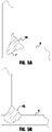
FIG. 5A illustrates a diagrammatical representation of an exemplary weld bead with a single wire and FIG. 5B illustrates a diagrammatical representation of an exemplary weld bead with an embodiment of the invention;
FIG. 6 illustrates a diagrammatical representation of an exemplary weld process flow chart for an embodiment of the present invention;
FIG. 7 illustrates a diagrammatical representation of an alternative embodiment of a contact tip assembly for use with embodiments of the present invention;
FIG. 8 illustrates a diagrammatical representation of an exemplary weld current waveform for embodiments of the present invention;
FIG. 9 illustrates a diagrammatical representation of a further exemplary weld current waveform for embodiments of the present invention;
FIG. 10 illustrates a diagrammatical representation of an additional exemplary weld current waveform for embodiments of the present invention;
FIG. 11 shows a portion of a welding torch;
FIG. 12 is a perspective view of a contact tip and diffuser;
FIG. 13 is a perspective view of a contact tip;
FIG. 14 is a perspective view of a contact tip;
FIG. 15 is a perspective view of a diffuser;
FIG. 16 is a perspective view of a diffuser;
FIG. 17 is a perspective view of a contact tip and bias spring;
FIG. 18 shows a perspective view of a contact tip, bias spring and diffuser;
FIG. 19 shows a portion of a welding torch;
FIG. 20 is a perspective view of a contact tip and diffuser;
FIG. 21 is a perspective view of a contact tip;
FIG. 22 is a perspective view of a contact tip and diffuser;
FIG. 23 is a perspective view of a contact tip and diffuser; and
FIG. 24 is a perspective view of a diffuser.
DETAILED DESCRIPTION OF EXEMPLARY EMBODIMENTS
Exemplary embodiments of the invention will now be described below by reference to the attached Figures. The described exemplary embodiments are intended to assist the understanding of the invention, and are not intended to limit the scope of the invention in any way. Like reference numerals refer to like elements throughout.
As used herein, “at least one”, “one or more”, and “and/or” are open-ended expressions that are both conjunctive and disjunctive in operation. For example, each of the expressions “at least one of A, B and C”, “at least one of A, B, or C”, “one or more of A, B, and C”, “one or more of A, B, or C” and “A, B, and/or C” means A alone, B alone, C alone, A and B together, A and C together, B and C together, or A, B and C together. Any disjunctive word or phrase presenting two or more alternative terms, whether in the description of embodiments, claims, or drawings, should be understood to contemplate the possibilities of including one of the terms, either of the terms, or both terms. For example, the phrase “A or B” should be understood to include the possibilities of “A” or “B” or “A and B.”
While embodiments of the present invention discussed herein are discussed in the context of GMAW type welding, other embodiments of the invention are not limited thereto. For example, embodiments can be utilized in SAW and FCAW type welding operations, as well as other similar types of welding operations. Further, while the electrodes described herein are solid electrodes, again, embodiments of the present invention are not limited to the use of solid electrodes as cored electrodes (either flux or metal cored) can also be used without departing from the spirit or scope of the present invention. Further, embodiments of the present invention can also be used in manual, semi-automatic and robotic welding operations. Because such systems are well known, they will not be described in detail herein.
Turning now to the Figures, FIG. 1 depicts an exemplary embodiment of a welding system 100 in accordance with an exemplary embodiment of the present invention. The welding system 100 contains a welding power source 109 which is coupled to both a welding torch 111 (having a contact tip assembly—not shown) and a wire feeder 105. The power source 109 can be any known type of welding power source capable of delivering the current and welding waveforms described herein, for example, pulse spray, STT and/or short arc type welding waveforms. Because the construction, design and operation of such power supplies are well known, they need not be described in detail herein. It is also noted that welding power can be supplied by more than one power supply at the same time—again the operation of such systems are known. The power source 109 can also include a controller 120 which is coupled to a user interface to allow a user to input control or welding parameters for the welding operation. The controller 120 can have a processor, CPU, memory etc. to be used to control the operation of the welding process as described herein. The torch 111, which can be constructed similar to known manual, semi-automatic or robotic welding torches can be coupled to any known or used welding gun and can be of a straight or gooseneck type as described above. The wire feeder 105 draws the electrodes E1 and E2 from electrode sources 101 and 103, respectively, which can be of any known type, such as reels, spools, containers or the like. The wire feeder 105 is of a known construction and employs feed rolls 107 to draw the electrodes E1 and E2 and push the electrodes to the torch 111. In an exemplary embodiment of the present invention, the feed rolls 107 and wire feeder 105 are configured for a single electrode operation. Embodiments of the present invention, using a dual wire configuration, can be utilized with a wire feeder 105 and rollers 107 only designed for a single wire feeding operation. For example, rollers 107 can be configured for a single 0.045 inch diameter electrode, but will suitable drive two electrodes of a 0.030 inch diameter without modification to the wire feeder 105 or the rollers 107. Alternatively, the wire feeder 105 can be designed to provide separate sets of rollers for feeding the electrodes E1/E2 respectively, or have rollers configured for feeding two or more electrodes simultaneously (e.g., via trapezoidal-shaped wire receiving grooves around the rollers that can accommodate two electrodes). In other embodiments, two separate wire feeders can also be used. As shown, the wire feeder(s) 105 is in communication with the power source 109 consistent with known configurations of welding operations.
Once driven by the rollers 107, the electrodes E1 and E2 are passed through a liner 113 to deliver the electrodes E1 and E2 to the torch 111. The liner 113 is appropriately sized to allow for the passage of the electrodes E1 and E2 to the torch 111. For example, for two 0.030 inch diameter electrodes, a standard 0.0625 inch diameter liner 113 (which is typically used for a single 0.0625 inch diameter electrode) can be used with no modification.
Although the examples referenced above discuss the use of two electrodes having a same diameter, the present invention is not limited in this regard as embodiments can use electrodes of a different diameter. That is, embodiments of the present invention can use an electrode of a first, larger, diameter and an electrode of a second, smaller, diameter. In such an embodiment, it is possible to more conveniently weld two work pieces of different thicknesses. For example, the larger electrode can be oriented to the larger work piece while the smaller electrode can be oriented to the smaller work piece. Further, embodiments of the present invention can be used for many different types of welding operations including, but not limited to, metal inert gas, submerged arc, and flux-cored welding. Further, embodiments of the present invention can be used for automatic, robotic and semi-automatic welding operations. Additionally, embodiments of the present invention can be utilized with different electrode types. For example, it is contemplated that a cored electrode can be coupled with a non-cored electrode. Further, electrodes of differing compositions can be used to achieve the desired weld properties and composition of the final weld bead. Thus, embodiments of the present invention can be utilized in a broad spectrum of welding operations.
FIG. 2 depicts an exemplary contact tip assembly 200 of the present invention. The contact tip assembly 200 can be made from known contact tip materials and can be used in any known type of welding gun. As shown in this exemplary embodiment, the contact tip assembly has two separate channels 201 and 203 which run the length of the contact tip assembly 200. During welding a first electrode E1 is passed through the first channel 201 and the second electrode E2 is passed through the second channel 203. The channels 201/203 are typically sized appropriately for the diameter of wire that is to be passed there through. For example, if the electrodes are to have the same diameter the channels will have the same diameters. However, if different diameters are to be used then the channels should be sized appropriately so as to properly transfer current to the electrodes. Additionally, in the embodiment shown, the channels 201/203 are configured such that the electrodes E1/E2 exit the distal end face of the contact tip 200 in a parallel relationship. However, in other exemplary embodiments the channels can be configured such that the electrodes E1/E2 exit the distal end face of the contact tip such that an angle in the range of +/−15° exists between the centerlines of the respective electrodes. The angling can be determined based on the desired performance characteristics of the welding operation. It is further noted that in some exemplary embodiments the contact tip assembly can be a single integrated contact tip with a channels as shown, while in other embodiments the contact tip assembly can be comprised of two contact tip subassemblies located close to each other, where the current is directed to each of the contact tip subassemblies.
As shown in FIG. 2, the respective electrodes E1/E2 are spaced by a distance S which is the distance between the closest edges of the electrodes. In exemplary embodiments of the present invention, this distance is in the range of 0.25 to 4 times the diameter of the larger of the two electrodes E1/E2, while in other exemplary embodiments the distance S is in the range of 2 to 3 times the largest diameter. For example, if each of the electrodes has a diameter of 1 mm, the distance S can be in the range of 2 to 3 mm. In other exemplary embodiments, the distance S is in the range of 0.25 to 2.25 times the diameter of one of the wire electrodes, such as the larger of the two electrodes. In manual or semi-automatic welding operations the distance S can be in the range of 0.25 to 2.25 times the largest electrode diameter, whereas in robotic welding operations the distance S can be in the same or another range, such as 2.5 to 3.5 times the largest electrode diameter. In exemplary embodiments, the distance S is in the range of 0.2 to 3.5 mm.
The wire electrodes E1/E2 project from exit orifices on the end face of the contact tip 200. The diameter of the exit orifices is slightly larger than the diameter of the wire electrodes E1/E2. For example, for a 0.035 inch wire, the diameter of the exit orifice could be 0.043 inches (1.09 mm); for a 0.040 inch wire, the diameter of the exit orifice could be 0.046 inches (1.17 mm); for a 0.045 inch wire, the diameter of the exit orifice could be 0.052 inches (1.32 mm). The channels 201, 203 and exit orifices are spaced appropriately to facilitate the formation of a single bridge droplet between the wire electrodes E1/E2 during a deposition operation. For exit orifices sized for electrodes having a diameter 0.045 inches and smaller, the distance between the exit orifices (inner circumference to inner circumference, similar to distance S) can be less than 3 mm to facilitate the formation of a bridge droplet. However, spacing of 3 mm or greater between the exit orifices may be possible, depending on the wire size, magnetic forces, orientation (e.g., angle) of the channels 201, 203, etc. In certain embodiments, the distance between the exit orifices is within the range of 20% to 200% of the diameter of one or both of the exit orifices, which can also correspond to the distance S between the wire electrodes being in the range of 0.25 to 2.25 times the diameter of the electrodes.
As explained further below, the distance S should be selected to ensure that a single bridge droplet is formed between the electrodes, before the droplet is transferred, while preventing the electrodes from contacting each other, other than through the bridge droplet.
FIG. 3A depicts an exemplary embodiment of the present invention, while showing in the interactions of the magnetic forces from the respective electrodes E1 and E2. As shown, due to the flow of current, a magnetic field is generated around the electrodes which tends to create a pinch force that draws the wires towards each other. This magnetic force tends to create a droplet bridge between the two electrodes, which will be discussed in more detail below.
FIG. 3B shows the droplet bridge that is created between the two electrodes. That is, as the current passing through each of the electrodes melts the ends of the electrodes the magnetic forces tend to draw the molten droplets towards each other until they connect with each other. The distance S is far enough such that the solid portions of the electrodes are not drawn to contact each other, but close enough that a droplet bridge is created before the molten droplet is transferred to the weld puddle created by the welding arc. The droplet is depicted in FIG. 3C where the droplet bridge creates a single large droplet that is transferred to the puddle during welding. As shown, the magnetic pinch force acting on the droplet bridge acts to pinch off the droplet similar to the use of pinch force in a single electrode welding operation.
Further, FIG. 4A depicts an exemplary representation of current flow in an embodiment of the present invention. As shown the welding current is divided so as to flow through each of the respective electrodes and passes to and through the bridge droplet as it is formed. The current then passes from the bridge droplet to the puddle and work piece. In exemplary embodiments where the electrodes are of the same diameter and type the current will be essentially divided evenly through the electrodes. In embodiments where the electrodes have different resistance values, for example due to different diameters and/or compositions/construction, the respective currents will be apportioned due to the relationship of V=I*R, as the welding current is applied to the contact tip similar to known methodologies and the contact tip provides the welding current to the respective electrodes via the contact between the electrodes and the channels of the contact tip. FIG. 4B depicts the magnetic forces within the bridge puddle that aid in creating the bridge droplet. As shown, the magnetic forces tend to pull the respective molten portions of the electrodes towards each other until they contact with each other.
FIG. 5A depicts an exemplary cross-section of a weld made with a single electrode welding operation. As shown, while the weld bead WB is of an appropriate width, the finger F of the weld bead WB, which penetrates into the work pieces W as shown, has a relatively narrow width. This can occur in single wire welding operations when higher deposit rates are used. That is, in such welding operations the finger F can become so narrow that it is not reliable to assume that the finger penetrated in the desired direction, and thus cannot be a reliable indicator of proper weld penetration. Further, as this narrow finger dives deeper this can lead to defects such as porosity trapped near the finger. Additionally, in such welding operations the useful sides of the weld bead are not as deeply penetrated as desired. Thus, in certain applications this mechanical bond is not as strong as desired. Additionally, in some welding applications, such as when welding horizontal fillet welds, the use of a single electrode made it difficult to achieve equal sized weld legs, at high deposition speeds, without the addition of too much heat to the welding operation. These issues are alleviated with embodiments of the present invention which can reduce the penetration of the finger and spread the finger making the side penetration of the weld wider. An example of this is shown in FIG. 5B, which shows a weld bead of an embodiment of the present invention. As shown in this embodiment, a similar, or improved weld bead leg symmetry and/or length can be achieved, as well as a wider weld bead at the weld depth within the weld joint. This improved weld bead geometry is achieved while using less overall heat input into the weld. Therefore, embodiments of the present invention can provide improved mechanical weld performance with lower amounts of heat input, and at improved deposition rates.
FIG. 6 depicts a flow chart 600 of an exemplary welding operation of the present invention. This flow chart is intended to be exemplary and is not intended to be limiting. As shown, a welding current/output is provided by the welding power source 610 such that current is directed to the contact tip and electrodes consistent with known system constructions. Exemplary waveforms are discussed further below. During welding a bridge droplet is allowed to form 620 between the electrodes where the respective droplets from each electrode contact each other to create a bridge droplet. The bridge droplet is formed prior to contacting the weld puddle. During formation of the bridge droplet at least one of a duration or a droplet size is detected until such time as the droplet reaches a size to be transferred, and then the droplet is transferred to the puddle 640. The process is repeated during the welding operation. To control the welding process the power source controller/control system can use either one of a bridge droplet current duration and/or a bridge droplet size detection to determine if the bridge droplet is of a size to be transferred. For example, in one embodiment a predetermined bridge current duration is used for a given welding operation such that a bridge current is maintained for that duration, after which droplet transfer is then initiated. In a further exemplary embodiment, the controller of the power source/supply can monitor the welding current and/or voltage and utilize a predetermined threshold (for example a voltage threshold) for a given welding operation. For example, in such embodiments, as the detected arc voltage (detected via a known type of arc voltage detection circuit) detects that the arc voltage has reached a bridge droplet threshold level the power supply initiates a droplet separation portion of the welding waveform. This will be discussed further below in some exemplary embodiments of welding waveforms that can be used with embodiments of the present invention.
FIG. 7 depicts an alternative exemplary embodiment of a contact tip 700 that can be used with embodiments of the present invention. As described previously, in some embodiments the electrodes can be directed to the torch via a single wire guide/liner. Of course, in other embodiments, separate wire guide/liners can be used. However, in those embodiments, where a single wire guide/liner is used the contact tip can be designed such that the electrodes are separated from each other within the contact tip. As shown in FIG. 7, this exemplary contact tip 700 has a single entrance channel 710 with a single orifice at the upstream end of the contact tip 700. Each of the electrodes enter the contact tip via this orifice and pass along the channel 710 until they reach a separation portion 720 of the contact tip, where the separation portion directs one electrode into a first exit channel 711 and a second electrode into the second exit channel 712, so that the electrodes are directed to their discrete exit orifices 701 and 702, respectively. Of course, the channels 710, 711 and 712 should be sized appropriately for the size of electrodes to be used, and the separation portion 720 should be shaped so as to not scar or scratch the electrodes. As shown in FIG. 7, the exit channels 711 and 712 are angled relative to each other, however, as shown in FIG. 2, these channels can also be oriented parallel to each other.
Turning now to FIGS. 8 through 10, various exemplary waveforms that can be used with exemplary embodiments of the present invention are depicted. In general, in exemplary embodiments of the present invention, the current is increased to create the bridge droplet and build it for transfer. In exemplary embodiments, at transfer the bridge droplet has an average diameter which is similar to the distance S between the electrodes, which can be larger than the diameter of either of the electrodes. When the droplet is formed it is transferred via a high peak current, after which the current drops to a lower (e.g. background) level to remove the arc pressure acting on the wires. The bridging current then builds the bridge droplet without exerting too much pinch force to pinch off the developing droplet. In exemplary embodiments, this bridging current is at a level in the range of 30 to 70% between the background current and the peak current. In other exemplary embodiments, the bridging current is in the range of 40 to 60% between the background current and the peak current. For example, if the background current is 100 amps and the peak current is 400 amps, the bridging current is in the range of 220 to 280 amps (i.e., 40 to 60% of the 300 amp difference). In some embodiments the bridging current can be maintained for a duration in the range of 1.5 to 8 ms, while in other exemplary embodiments the bridging current is maintained for a duration in the range of 2 to 6 ms. In exemplary embodiments the bridging current duration begins at the end of the background current state and includes the bridging current ramp up, where the ramp up can be in the range of 0.33 to 0.67 ms depending on the bridging current level and the ramp rate. With exemplary embodiments of the present invention, the pulse frequency of waveforms can be slowed down as compared to single wire processes to allow for droplet growth which can improve control and allow for higher deposition rates as compared to single wire operations.
FIG. 8 depicts an exemplary current waveform 800 for a pulsed spray welding type operation. As shown, the waveform 800 has a background current level 810, which then transitions to a bridge current level 820, during which the bridge droplet is grown to a size to be transferred. The bridge current level is less than a spray transition current level 840 at which the droplet starts its transfer to the puddle. At the conclusion of the bridge current 820 the current is raised to beyond the spray transition current level 840 to a peak current level 830. The peak current level is then maintained for a peak duration to allow for the transfer of the droplet to be completed. After transfer the current is then lowered to the background level again, as the process is repeated. Thus, in these embodiments the transfer of the single droplet does not occur during the bridge current portion of the waveform. In such exemplary embodiments, the lower current level for the bridge current 820 allows a droplet to form without excessive pinching force to direct the droplet to the puddle. Because of the use of the bridge droplet, welding operations can be attained where the peak current 830 can be maintained for a longer duration at a higher level than using a single wire. For example, some embodiments can maintain the peak duration for at least 4 ms, and in the range of 4 to 7 ms, at a peak current level in the range of 550 to 700 amps, and a background current in the range of 150 to 400 amps. In such embodiments, a significantly improved deposition rate can be achieved. For example, some embodiments have achieved deposition rates in the range of 19 to 26 lbs/hr, whereas similar single wire processes can only achieve a deposition rate in the range of 10 to 16 lbs/hr. For example, in one non-limiting embodiment a pair of twin wires having a diameter of 0.040″, using a peak current of 700 amps, a background current of 180 amps and a droplet bridge current of 340 amps can be deposited at a rate of 19 lb/hr at a frequency of 120 Hz. Such a deposition is at a frequency much less than conventional welding processes, and thus more stable.
FIG. 9 depicts another exemplary waveform 900 that can be used in a short arc type welding operation. Again, the waveform 900 has a background portion 910 prior to a short response portion 920 which is structured to clear a short between the droplet and the puddle. During the shorting response 920 the current is raised to clear the short and as the short is cleared the current is dropped to a bridge current level 930 during which the bridge droplet is formed. Again, the bridge current level 930 is less than the peak current level of the shorting response 920. The bridge current level 930 is maintained for a bridge current duration that allows a bridge droplet to be formed and directed to the puddle. During transfer of the droplet current is then dropped to the background level, which allows the droplet to advance until a short occurs. When a short occurs the shorting response/bridge current waveform is repeated. It should be noted that in embodiments of the present invention it is the presence of the bridge droplet that makes the welding process more stable. That is, in traditional welding processes that use multiple wires there is no bridge droplet. In those processes when one wire shorts or makes contact with the puddle the arc voltage drops and the arc for the other electrode will go out. This does not occur with embodiments of the present invention, where the bridge droplet is common to each of the wires.
FIG. 10 depicts a further exemplary waveform 1000, which is a STT (surface tension transfer) type waveform. Because such waveforms are known, they will not be described in detail herein. To further explain an STT type waveform, its structure, use and implementation, US. Publication No. 2013/0264323, filed on Apr. 5, 2012, is incorporated herein in its entirety. Again, this waveform has a background level 1010, and a first peak level 1015 and a second peak level 1020, where the second peak level is reached after a short between the droplet and puddle is cleared. After the second peak current level 1020, the current is dropped to a bridge current level 1030 where the bridge droplet is formed, after which the current is dropped to the background level 1010 to allow the droplet to be advanced to the puddle, until it makes contact with the puddle. In other embodiments, an AC waveform can be used, for example an AC STT waveform, pulse waveform, etc. can be used.
As discussed above, the wire electrodes used in a multi-wire deposition operation (e.g., welding, additive manufacturing, hardfacing, etc.) can be spaced by a distance S that facilitates formation of a bridge droplet between the wire electrodes. The size of the bridge droplet is determined by the spacing between the wire electrodes and the spacing between the exit orifices in the contact tip. The size of the bridge droplet determines the width of the electric arc that exists during the deposition operation, and reducing the spacing between the exit orifices and wire electrodes narrows the arc width. Larger bridge droplets may be preferred for larger welds, and smaller bridge droplets preferred for smaller welds. Deposition rate is impacted by the arc width, and the deposition rate for small gauge wires can be increased by reducing the spacing between the exit orifices and wire electrodes (e.g., from approximately 2 mm to 1 mm).
The maximum spacing between the exit orifices and between the wire electrodes is reached when the magnetic forces developed by the current waveform (e.g., at the peak current level) still allow formation of the bridge droplet, and is exceeded when bridging is no longer possible. The minimum spacing is that which keeps the wires separated at the point of bridging. The magnetic forces tend to pull the wire electrodes together, and the wires are somewhat flexible. Thus, the minimum spacing between the exit orifices and between the wire electrodes will depend on the stiffness of the electrodes, which is impacted by parameters such as wire diameter, material of construction, etc.
FIG. 11 depicts an end portion of an exemplary welding torch in accordance with the present invention. Because the construction and operation of welding torches is generally known, the details of such construction and operation will not be discussed in detail herein. As shown, the torch includes a number of components and is used to deliver at least two wire electrodes and a shielding gas to a workpiece for a welding or additive manufacturing operation. The torch includes a diffuser 205 which aids in properly directing and distributing the shielding gas for a welding operation. Coupled to the downstream end of the diffuser 205 is a contact tip 200, which is used to pass the welding current into the at least two wire electrodes which are passing though the contact tip simultaneously during welding. The contact tip 200 is configured to facilitate the formation of a bridge droplet between the wire electrodes that are delivered through bores or channels in the contact tip. The bridge droplet couples the first wire electrode to the second wire electrode prior to contacting a molten puddle created by the deposition operation, as discussed above.
Threaded onto the outside of the diffuser 205 is an insulator 206. The insulator 206 electrically isolates a nozzle 204 from the electrically live components within the torch. The nozzle 204 directs the shielding gas from the diffuser 205 to the distal end of the torch and the workpiece during welding.
Conventional contact tips have threads on an upstream or proximal end of the contact tip that thread into the diffuser. The contact tip and diffuser are connected by screwing the contact tip into the diffuser. Such a fastening system works well for welding with single wires. The welding wire can be threaded through the contact tip and the contact tip can be rotated around the wire multiple times and screwed into the diffuser. However, when welding with multiple welding wires simultaneously passing through the contact tip, such a fastening system would result in an undesirable twisting of the welding wires. For example, if two welding wires are passed through the contact tip, subsequently threading the contact tip onto the diffuser by multiple turns requiring greater than 360° of rotation will result in the welding wires becoming twisted and unable to be fed through the contact tip.
The contact tip 200 in FIG. 11 is attached to the diffuser 205 by rotation of the contact tip through less than 360°, such as 270° (three-quarter turn), 180° (one-half turn), 90° (quarter turn), less than 90°, etc. The rotation of the contact tip 200 necessary to attach the contact tip to the diffuser 205 can be any angle as desired that is preferably less than 360° and results in the multiple wire electrodes passing through the contact tip not becoming unduly twisted during installation of the contact tip. If the welding wires are unduly twisted during installation of the contact tip, wire feeding problems will result and “bird nesting” of the welding wires can occur.
With reference to FIGS. 11-16, the contact tip 200 is attached to the diffuser 205 by a quarter turn, clockwise rotation of the contact tip within the diffuser. The contact tip 200 has a forward or downstream distal portion that has a tapered shape and includes flats 215 to accommodate gripping by a tool, such as pliers. The contact tip 200 has a rearward or upstream proximal portion 208 that is generally cylindrical, but includes a radially-projecting tab 210 that engages a slot 212 in an interior wall of the diffuser 205, to securely connect the contact tip to the diffuser. The rearward portion 208 of the contact tip 200 is located within the diffuser 205 when the contact tip is installed onto the diffuser, and acts as a mounting shank for the contact tip. It can be seen that the diameter of the rearward portion 208 of the contact tip is smaller than the adjacent downstream portion, which results in a shoulder 211 projecting radially from the cylindrical rearward portion 208 of the contact tip. The shoulder 211 seats against the terminal end face of the diffuser 205 when the contact tip 200 is installed onto the diffuser.
The contact tip 200 can be made from known contact tip materials and can be used in any known type of welding gun. The contact tip can comprise an electrically-conductive body, such as copper, extending from its rearward, proximal end to its forward, distal end. As shown in this exemplary embodiment, the contact tip 200 has two separate wire channels or bores 214 and 216 which run the length of the contact tip. The channels 214/216 can extend between wire entrance orifices on the proximal end face of the mounting shank 208, and wire exit orifices on the distal end face of the contact tip. During welding, a first wire electrode is delivered through the first channel 214 and a second wire electrode is delivered through the second channel 216. The channels 214/216 are typically sized appropriately for the diameter of wire that is to be fed through the channel. For example, if the electrodes are to have the same diameter, then the channels will have the same diameters. However, if different wire sizes are to be used together, then the channels should be sized appropriately so as to properly transfer current to the differently-sized electrodes. Additionally, in the embodiment shown, the channels 214/216 are configured such that the electrodes exit the distal end face of the contact tip 200 in a parallel relationship. However, in other exemplary embodiments the channels can be configured so that the electrodes exit the distal end face of the contact tip such that an angle in the range of +/−15° exists between the centerlines of the respective electrodes. The angling can be determined based on the desired performance characteristics of the welding operation. The example contact tips discussed herein are shown having two electrode bores. However, it is to be appreciated that the contact tips could have bores for more than two electrodes, such as three or more bores.
The slot 212 in the interior wall of the diffuser 205 includes an axial portion 218 and a helical portion 220. The axial portion 218 of the slot 212 extends to the downstream terminal end face of the diffuser 205, against which the shoulder 211 of the contact tip 200 seats. After the welding electrodes are fed through the contact tip 200, the radially-projecting tab 210 on the mounting shank 208 is inserted into the axial portion 218 of the 212 slot and the contact tip is pushed into the diffuser 205. When the tab 210 reaches the helical portion 220 of the slot, the contact tip 200 is rotated to move the tab to the end of the helical portion. The helical portion 220 has a slight upstream pitch that draws the contact tip 200 inward as the contact tip is rotated, so that the shoulder 211 of the contact tip seats against the downstream terminal end face of the diffuser 205. The tab 210 on the mounting shank 208 can have a tapered edge 217 that matches the pitch of the slot 212 in the diffuser 205, to help ensure a tight connection between the two components. In the example embodiment shown, the helical portion 220 of the slot 212 allows for a quarter turn of the contact tip 200 to secure the contact tip to the diffuser 205. However, it is to be appreciated that other rotational angles are possible (e.g., more or less than a quarter turn or 90°). For example, the helical portion 220 of the slot can extend less than 360° around the inner circumference of the interior chamber of the diffuser 205.
FIGS. 17 and 18 show an example embodiment of a contact tip 200 that includes a biasing mechanism to provide an axial force between the contact tip and the diffuser 205. The illustrated biasing mechanism is a bias spring 222, such as a wave washer. The bias spring 222 is compressed when the contact tip 200 is mounted to the diffuser 205, to maintain an axial force between the contact tip and diffuser. The axial force helps to seat the radially-projecting tab 210 on the mounting shank 208 in the slot 212 in the diffuser 205. In particular, the axial force can push the tapered surface of the tab 210 against the sidewall of the slot in the diffuser 205, to help secure the contact tip in place and resist loosening (e.g., due to thermal cycling, mechanical impacts, etc.) The mounting shank 208 extends from the shoulder portion 211 of the contact tip 200, and the bias spring 222 can be arranged annularly around the mounting shank, between the radially-projecting tab and the shoulder portion. The bias spring 222 can be captured on the mounting shank 208, such that it cannot be removed without damaging the bias spring or contact tip. Various types of biasing mechanisms could be used to maintain an axial force between the contact tip 200 and diffuser 205, such as lock washers or coil springs for example.
FIGS. 19-24 illustrate a further embodiment of a contact tip 302 and diffuser 300 for multiwire welding or additive manufacturing. The contact tip 302 requires no rotation when installed onto the diffuser 300, as will be described further below. The nozzle 204 and insulator portion 206 of the welding torch are substantially similar to the embodiment of FIG. 7. Also, the contact tip 302 includes wire channels 214/216 and a shoulder 211 as discussed above.
The contact tip 302 and diffuser 300 are keyed so that there is only one possible installed orientation between the contact tip and diffuser. The interior surface 304 of the diffuser and the rearward portion 306 or mounting shank of the contact tip are shown as having corresponding flats that key the diffuser and contact tip. However, other keying mechanisms could be used, such as a slot and projection keying mechanism for example.
After the welding electrodes are passed through the contact tip 302, the contact tip is inserted axially into the diffuser 300 without twisting or rotating the contact tip. The diffuser 300 is a collet style and clamps tightly against the rearward portion 306 of the contact tip, holding it in place by friction. The diffuser 300 can include a number slots 308, 310, 312 that allow the downstream end of the diffuser to expand slightly as the contact tip 302 is inserted into the diffuser. The expansion of the downstream end of the diffuser 300 results in a clamping force applied radially onto the rearward portion 306 of the contact tip. If desired, an additional clamping mechanism can be used to further secure the contact tip 302 within the diffuser 300. For example, a set screw could fasten the contact tip to the diffuser, or a clamp could further compress the downstream end of the diffuser around the rearward portion of the contact tip. Such a clamp could be threaded onto the diffuser such that the clamping force applied to the downstream end of the diffuser is provided by the axial movement of the clamp as it is threaded onto the diffuser.
The use of embodiments described herein can provide significant improvements in stability, weld structure and performance over known welding operations. However, in addition to welding operations, embodiments can be used in additive manufacturing operations. In fact the system 100 described above can be used in additive manufacturing operations as in welding operations. In exemplary embodiments, improved deposition rates can be achieved in additive manufacturing operations. For example, when using an STT type waveform in a single wire additive process, using an 0.045″ wire can provide a deposition rate of about 5 lb/hr before becoming unstable. However, when using embodiments of the present invention and two 0.040″ wires a deposition rate of 7 lbs/hr can be achieved in a stable transfer. Because additive manufacturing processes and systems are known, the details of which need not be described herein. In such processes a bridging current, such as that descried above, can be used in the additive manufacturing current waveform.
It is noted that exemplary embodiments are not limited to the usage of the waveforms discussed above and described herein, as other welding type waveforms can be used with embodiments of the present invention. For example, other embodiments can use variable polarity pulsed spray welding waveforms, AC waveforms, etc. without departing from the spirit and scope of the present invention. For example, in variable polarity embodiments the bridge portion of the welding waveform can be done in a negative polarity such that the bridge droplet is created while reducing the overall heat input into the weld puddle. For example, when using AC type waveforms, the waveforms can have a frequency of 60 to 200 Hz of alternating negative and positive pulses to melt the two wires and form the bridge droplet between them. In further embodiments the frequency can be in the range of 80 to 120 Hz.
As explained previously, embodiments of the present invention can be used with different types and combinations of consumables including flux cored consumables. In fact, embodiments of the present invention can provide a more stable welding operation when using flux cored electrodes. Specifically, the use of a bridging droplet can aid in stabilizing flux core droplets that can tend to be unstable in a single wire welding operation. Further, embodiments of the present invention allow for increased weld and arc stability at higher deposition rates. For example, in single wire welding operations, at high current and high deposition rates the transfer type for the droplets can change from streaming spray to a rotational spray, which appreciably reduces the stability of the welding operation. However, with exemplary embodiments of the present invention the bridge droplet stabilizes the droplets which significantly improves arc and weld stability at high deposition rates, such as those above 20 lb/hr.
Additionally, as indicated above the consumables can be of different types and/or compositions, which can optimize a given welding operation. That is, the use of two different, but compatible, consumables can be combined to create a desired weld joint. For example, compatible consumables include hardfacing wires, stainless wires, nickel alloys and steel wires of different composition can be combined. As one specific example a mild steel wire can be combined with an overalloyed wire to make a 309 stainless steel composition. This can be advantageous when a single consumable of the type desired does not have desirable weld properties. For example, some consumables for specialized welding provide the desired weld chemistry but are extremely difficult to use and have difficulty providing a satisfactory weld. However, embodiments of the present invention allow for the use of two consumables that are easier to weld with to be combined to create the desired weld chemistry. Embodiments of the present invention can be used to create an alloy/deposit chemistry that is not otherwise commercially available, or otherwise very expensive to manufacture. Thus, two different consumables can be used to obviate the need for an expensive or unavailable consumable. Further, embodiments can be used to create a diluted alloy. For example, a first welding wire could be a common inexpensive alloy and a second welding wire could be a specialty wire. The desired deposit would be the average of the two wires, mixed well in the formation of the bridged droplet, at the lower average cost of the two wires, over an expensive specialty wire. Further, in some applications, the desired deposit could be unavailable due to the lack of appropriate consumable chemistry, but could be reached by mixing two standard alloy wires, mixed within the bridged droplet and deposited as a single droplet. Further, in some applications, such as the application of wear resistance metals, the desired deposit may be combination of tungsten carbide particles from one wire and chrome carbide particles from another. Still in another application, a larger wire housing larger particles within is mixed with a smaller wire containing fewer particles or smaller particles, to deposit a mixture of the two wires. Here the expected contribution from each of the wires is proportional to the size of wire given the wire feed speeds are same. In yet another example, the wire feed speeds of the wires are different to allow the alloy produced to change based on the desired deposit but the mixing of the wires is still produced by the bridged droplet created between the wires.
While the invention has been particularly shown and described with reference to exemplary embodiments thereof, the invention is not limited to these embodiments. It will be understood by those of ordinary skill in the art that various changes in form and details may be made therein without departing from the spirit and scope of the invention as defined by the following claims.

Claims (18)

What is claimed is:
1. A welding or additive manufacturing contact tip, comprising:
a single electrically-conductive body extending from a proximal end of the single electrically-conductive body to a distal end of the single electrically-conductive body, wherein the single electrically-conductive body comprises a mounting shank at the proximal end, and one or more entrance orifices are located on the mounting shank, wherein the single electrically-conductive body further comprises a shoulder portion and the mounting shank extends from the shoulder portion and has a different diameter than the shoulder portion, and wherein the single electrically-conductive body forms:
a first bore terminating at the distal end; and
a second bore terminating at the distal end;
wherein, at the distal end, the first bore and the second bore are separated from each other by a distance configured to facilitate formation of a bridge droplet between a first wire electrode delivered through the first bore and a second wire electrode delivered through the second bore, while preventing solid portions of the first wire electrode delivered through the first bore from contacting solid portions of the second wire electrode delivered through the second bore, during a deposition operation in which electrical current is conducted to both of the first wire electrode and the second wire electrode simultaneously through the contact tip.
2. The welding or additive manufacturing contact tip of claim 1, wherein the first bore extends distally to a first exit orifice, and the second bore extends distally to a second exit orifice, and wherein the first exit orifice has a diameter, and said distance is within a range of 20% to 200% of said diameter.
3. The welding or additive manufacturing contact tip of claim 1, wherein said distance provides a spacing between the first wire electrode and the second wire electrode that is within a range of 0.25 to 2.25 times a diameter of the first and second wire electrodes, as measured between closest edges of the first and second wire electrodes.
4. The welding or additive manufacturing contact tip of claim 1, wherein said distance is less than 3 mm.
5. The welding or additive manufacturing contact tip of claim 1, wherein the mounting shank includes a radially-projecting tab.
6. The welding or additive manufacturing contact tip of claim 5, wherein the radially-projecting tab has a tapered edge.
7. A welding or additive manufacturing contact tip, comprising:
a single electrically-conductive body extending from a proximal end of the single electrically-conductive body to a distal end of the single electrically-conductive body, wherein the single electrically-conductive body comprises, at the proximal end, means for attaching the contact tip to a diffuser, and one or more entrance orifices are located at the proximal end, wherein the single electrically-conductive body further comprises a shoulder portion and the means for attaching the contact tip to a diffuser extends from the shoulder portion and has a different diameter than the shoulder portion, and wherein the single electrically-conductive body forms:
a first bore terminating at the distal end; and
a second bore terminating at the distal end;
wherein, at the distal end, the first bore and the second bore are separated from each other by a distance configured to facilitate formation of a bridge droplet between a first wire electrode delivered through the first bore and a second wire electrode delivered through the second bore, while preventing solid portions of the first wire electrode delivered through the first bore from contacting solid portions of the second wire electrode delivered through the second bore, during a deposition operation in which electrical current is conducted to both of the first wire electrode and the second wire electrode simultaneously through the contact tip.
8. The welding or additive manufacturing contact tip of claim 7, wherein the first bore extends distally to a first exit orifice, and the second bore extends distally to a second exit orifice, and wherein the first exit orifice has a diameter, and said distance is within a range of 20% to 200% of said diameter.
9. The welding or additive manufacturing contact tip of claim 7, wherein said distance provides a spacing between the first wire electrode and the second wire electrode that is within a range of 0.25 to 2.25 times a diameter of the first and second wire electrodes, as measured between closest edges of the first and second wire electrodes.
10. The welding or additive manufacturing contact tip of claim 7, wherein said distance is less than 3 mm.
11. The welding or additive manufacturing contact tip of claim 7, wherein the means for attaching the contact tip to a diffuser includes a radially-projecting tab.
12. The welding or additive manufacturing contact tip of claim 11, wherein the radially-projecting tab has a tapered edge.
13. The welding or additive contact tip of claim 12, wherein said diameter is smaller than a diameter of the shoulder portion.
14. The welding or additive contact tip of claim 13, wherein the single electrically-conductive body further comprises a distal portion having a tapered shape, and flats to accommodate gripping by a tool.
15. The welding or additive contact tip of claim 14, wherein the shoulder portion is located between the radially-projecting tab and the flats.
16. The welding or additive contact tip of claim 6, wherein the diameter of the mounting shank is smaller than a diameter of the shoulder portion.
17. The welding or additive contact tip of claim 16, wherein the single electrically-conductive body further comprises a distal portion having a tapered shape, and flats to accommodate gripping by a tool.
18. The welding or additive contact tip of claim 17, wherein the shoulder portion is located between the radially-projecting tab and the flats.
US16/658,681 2017-08-08 2019-10-21 Dual wire welding or additive manufacturing contact tip and diffuser Active 2038-06-05 US11484960B2 (en)

Priority Applications (1)

Application Number Priority Date Filing Date Title
US16/658,681 US11484960B2 (en) 2017-08-08 2019-10-21 Dual wire welding or additive manufacturing contact tip and diffuser

Applications Claiming Priority (4)

Application Number Priority Date Filing Date Title
US15/671,295 US10792752B2 (en) 2017-08-08 2017-08-08 Dual wire welding or additive manufacturing system and method
US201862750893P 2018-10-26 2018-10-26
US16/295,571 US10532418B2 (en) 2017-08-08 2019-03-07 Dual wire welding or additive manufacturing contact tip and diffuser
US16/658,681 US11484960B2 (en) 2017-08-08 2019-10-21 Dual wire welding or additive manufacturing contact tip and diffuser

Related Parent Applications (1)

Application Number Title Priority Date Filing Date
US16/295,571 Continuation US10532418B2 (en) 2017-08-08 2019-03-07 Dual wire welding or additive manufacturing contact tip and diffuser

Publications (2)

Publication Number Publication Date
US20200047275A1 US20200047275A1 (en) 2020-02-13
US11484960B2 true US11484960B2 (en) 2022-11-01

Family

ID=67059221

Family Applications (2)

Application Number Title Priority Date Filing Date
US16/295,571 Active US10532418B2 (en) 2017-08-08 2019-03-07 Dual wire welding or additive manufacturing contact tip and diffuser
US16/658,681 Active 2038-06-05 US11484960B2 (en) 2017-08-08 2019-10-21 Dual wire welding or additive manufacturing contact tip and diffuser

Family Applications Before (1)

Application Number Title Priority Date Filing Date
US16/295,571 Active US10532418B2 (en) 2017-08-08 2019-03-07 Dual wire welding or additive manufacturing contact tip and diffuser

Country Status (1)

Country Link
US (2) US10532418B2 (en)

Families Citing this family (7)

* Cited by examiner, † Cited by third party
Publication number Priority date Publication date Assignee Title
US11504788B2 (en) 2017-08-08 2022-11-22 Lincoln Global, Inc. Dual wire welding or additive manufacturing system and method
US11440121B2 (en) 2017-08-08 2022-09-13 Lincoln Global, Inc. Dual wire welding or additive manufacturing system and method
US10532418B2 (en) 2017-08-08 2020-01-14 Lincoln Global, Inc. Dual wire welding or additive manufacturing contact tip and diffuser
US11285557B2 (en) 2019-02-05 2022-03-29 Lincoln Global, Inc. Dual wire welding or additive manufacturing system
US11498146B2 (en) 2019-09-27 2022-11-15 Lincoln Global, Inc. Dual wire welding or additive manufacturing system and method
AU2021200311A1 (en) * 2020-01-27 2021-08-12 Lincoln Global, Inc. Dual wire welding or additive manufacturing system and method
WO2022035821A2 (en) 2020-08-12 2022-02-17 The Esab Group Inc. Arc welding, cladding, and additive manufacturing method and apparatus

Citations (166)

* Cited by examiner, † Cited by third party
Publication number Priority date Publication date Assignee Title
US1368287A (en) 1920-06-23 1921-02-15 Harry R Pennington Arc-welding electrode
US1605860A (en) 1926-01-02 1926-11-02 Walter O Snelling Thermocouple
US2583507A (en) 1949-04-04 1952-01-22 Babcock & Wilcox Co Polyphase alternating current fusion welding with control of interphase voltage, andwith combined alternating current and direct current welding potentials
US2594333A (en) 1951-03-13 1952-04-29 Gustav K Medicus Gas arc torch
US2756311A (en) 1954-03-24 1956-07-24 Union Carbide & Carbon Corp High-speed tandem arc working
US2849593A (en) 1952-05-21 1958-08-26 Air Liquide Electric arc welding
US2866079A (en) 1957-02-18 1958-12-23 Westinghouse Electric Corp Arc welding apparatus
US2911517A (en) * 1957-12-10 1959-11-03 Babcock & Wilcox Co Twin electrode welding method and apparatus
US2957101A (en) 1957-06-18 1960-10-18 Evans Reamer And Machine Compa Electrical contactor device for continuous feed, consumable electrodetype welding apparatus
DE1115382B (en) 1959-10-06 1961-10-19 Philips Nv Process for inert gas arc welding with two wire electrodes under carbon dioxide
US3131325A (en) 1961-02-17 1964-04-28 Electrarc Inc Arc welding system
GB990208A (en) 1961-11-25 1965-04-28 Boehler & Co Ag Geb Improvements in or relating to welding processes
US3274371A (en) 1965-06-01 1966-09-20 Union Carbide Corp Method of depositing metal
US3328556A (en) 1965-10-20 1967-06-27 Battelle Development Corp Process for narrow gap welding
US3384778A (en) 1964-12-31 1968-05-21 Air Reduction Touch starting of power arcs with consumable electrode
DE2108614A1 (en) 1970-04-03 1971-10-21 Boehler & Co Ag Geb Arc welding using strip and wire electrodes
US3624345A (en) 1968-10-31 1971-11-30 Babcock & Wilcox Co Arc welding electrode arrangements
US3693858A (en) 1970-07-24 1972-09-26 Hitachi Ltd Device for feeding a consumable wire electrode to an arc welding torch
US3694620A (en) 1970-12-10 1972-09-26 William R Gleason Dual welding wire feed for arc welder
US3746833A (en) 1972-02-14 1973-07-17 Mitsubishi Heavy Ind Ltd Process and apparatus for triple-electrode mig welding using short-circuit and spray-arc deposition
US3933533A (en) 1973-04-18 1976-01-20 Nippon Steel Corporation Method and apparatus for initiating scarfing
US4012621A (en) 1973-08-06 1977-03-15 Nippon Steel Corporation Consumable electrode for initiating scarfing
GB1502288A (en) 1974-02-25 1978-03-01 Akad Tekn Videnskaber Method and an apparatus for automatic electric welding
US4088866A (en) 1974-02-25 1978-05-09 Akademiet For De Tekniske Videnskaber, Svejsecentralen Method and an apparatus for automatic electric welding
US4182947A (en) 1975-12-10 1980-01-08 Brower Jerome S Underwater cutting rod
GB2058637A (en) 1979-09-07 1981-04-15 Messer Griesheim Gmbh Process for arc welding
US4295746A (en) 1979-09-04 1981-10-20 International Business Machines Corporation Arrangement for feeding electrodes in metal paper printers
US4336441A (en) 1978-10-27 1982-06-22 Kobe Steel, Ltd. Welding process
US4437906A (en) 1982-03-26 1984-03-20 Kawasaki Steel Corporation Flux composition for electro-slag over-lay welding of a cylindrical vessel with a strip electrode
US4475996A (en) 1982-03-03 1984-10-09 Inoue-Japax Research Incorporated Multi-strand wire electroerosion machining method and apparatus
US4541616A (en) 1984-05-23 1985-09-17 Dean Jessie L Thermal burning rod
SU1237347A1 (en) 1984-07-03 1986-06-15 Ждановский металлургический институт Method of multielectrode arc working of metals
US4697791A (en) 1985-12-31 1987-10-06 Arcair Company Exothermic cutting electrode
US4743731A (en) 1987-07-30 1988-05-10 Seuring Gene E Disintegrating electrodes
US4902873A (en) 1978-12-25 1990-02-20 Ivannikov Alfred V Method of electric arc welding
JPH02258168A (en) 1988-08-31 1990-10-18 Kawasaki Steel Corp Method and apparatus of arc welding and flux cored wire
US4968867A (en) 1988-06-30 1990-11-06 Mitsubishi Denki Kabushiki Kaisha Wire electrode for wire cut electric discharge machining
JPH02280968A (en) 1989-04-21 1990-11-16 Nippon Steel Corp Horizontal filter gas shielded arc welding method at high speed
JPH0453617B2 (en) 1988-06-30 1992-08-27 Kawasaki Steel Co
US5148001A (en) 1986-12-11 1992-09-15 The Lincoln Electric Company System and method of short circuiting arc welding
DE4204661C1 (en) 1992-02-17 1993-06-24 Weltron Steuerungs Schweissanlagenbau Intermittent submerged arc welding seams mfr. - with wire feed reversal at end of weld for reliable reignition of arc
US5324552A (en) 1990-06-21 1994-06-28 Deutsche Forschungsanstalt Fuer Luft-Und Raumfahrt E.V. Process for coating substrate material
US5440100A (en) 1992-02-26 1995-08-08 Tweco Products, Inc. Tips and diffusers for MIG welding guns
US5491321A (en) 1992-02-26 1996-02-13 Tweco Products, Inc. Welding gun assembly
US5635091A (en) 1993-04-21 1997-06-03 Babcock-Hitachi Kabushiki Kaisha Tips for welding and their manufacturing process
DE19611597A1 (en) 1996-03-23 1997-09-25 Fichtel & Sachs Ag Apparatus for welding with two wires
DE19611583A1 (en) 1996-03-23 1997-09-25 Fichtel & Sachs Ag Apparatus for welding with two wires
JPH09267170A (en) 1996-03-29 1997-10-14 Osaka Gas Co Ltd Gas shielded metal arc welding method
WO1997045227A1 (en) 1996-05-29 1997-12-04 Fronius Schweissmaschinen Kg Austria Wire-guiding elements for a plurality of approximately mutually parallel welding wires for a welding torch
US5714735A (en) 1996-06-20 1998-02-03 General Electric Company Method and apparatus for joining components with multiple filler materials
JPH10113771A (en) 1996-10-08 1998-05-06 Mitsubishi Heavy Ind Ltd Device for feeding wire for plural electrode gas shield arc weldings
US5782987A (en) 1997-05-02 1998-07-21 Furman; James Edmond MIG welder wire cleaning apparatus and method
US5791560A (en) 1996-12-09 1998-08-11 Thermion, Inc. Method and apparatus for spraying metal to form a coating
US5816466A (en) 1996-04-19 1998-10-06 The Lincoln Electric Company Wire feeding apparatus
US5958261A (en) 1997-07-17 1999-09-28 General Electric Company Apparatus for welding with preheated filler material
US5977504A (en) 1997-07-17 1999-11-02 General Electric Company Method and apparatus for guiding multiple filler wires in welding groove
US5981906A (en) 1995-08-11 1999-11-09 Lincoln Global, Inc. Method of welding the ends of pipe together using dual welding wires
DE29819828U1 (en) 1998-11-06 1999-11-25 Cloos Innovations Gmbh Welding device for inert gas metal welding with wire electrodes
US6172333B1 (en) 1999-08-18 2001-01-09 Lincoln Global, Inc. Electric welding apparatus and method
KR20010002945A (en) 1999-06-18 2001-01-15 김형벽 Automatic system for detecting the remain of welding wire
US6225589B1 (en) 1999-03-15 2001-05-01 Stephen Bartok Electric discharge machining apparatus
US20010008235A1 (en) 1999-01-08 2001-07-19 Edward S. Miszczak Ultra low carbon metal-core weld wire
DE19738785C2 (en) 1997-09-04 2001-12-13 Leipold & Co Gmbh Arc welding device with melting electrode
US6374655B1 (en) 1998-01-10 2002-04-23 Spintex Ag Spring winding automatic machine
US6512220B1 (en) 1999-06-28 2003-01-28 Hyundai Electronics Industries Co., Ltd. Semiconductor image sensor incorporating therein optical layer
US6512200B2 (en) 2000-01-27 2003-01-28 Crc For Welded Structures, Limited Welding control system
US6627839B1 (en) 2000-02-14 2003-09-30 Stephen Luckowski Dual-torch gas metal arc pulse welding for overlay applications
US20030209530A1 (en) 2002-05-10 2003-11-13 Tweco Products, Inc. Welding contact tip and diffuser
US6683279B1 (en) 2001-12-27 2004-01-27 Delford A. Moerke Twin MIG welding apparatus
US6683271B2 (en) 2001-12-04 2004-01-27 Frank S. Rogers Voltage controlled arc spray
US20040016735A1 (en) 2002-07-23 2004-01-29 Gerd Huismann Method and apparatus for retracting and advancing a welding wire
US6737616B1 (en) 2003-04-02 2004-05-18 Tutco, Inc. Open coil electric resistance heater using twisted resistance wires and methods of making
CN2683302Y (en) 2004-03-10 2005-03-09 上海东升焊接设备有限公司 Single power supply twin-wire automatic submerged-arc welding machine
US20050218132A1 (en) 2004-03-31 2005-10-06 Wells Jeff G Method and apparatus for securing welding torch components
US20050224486A1 (en) 2004-04-08 2005-10-13 Illinois Tool Works Inc. Wire feeder pinch force mechanism
US20050230373A1 (en) 2004-04-05 2005-10-20 Kensrue Milo M Welding gun contact tip
US20060070985A1 (en) 2004-10-05 2006-04-06 Fanuc Ltd Arc welding device and arc welding robot system
US20060081675A1 (en) 2004-10-14 2006-04-20 Lincoln Global, Inc. Coating wire drive parts
US20060138115A1 (en) 2002-06-03 2006-06-29 John Norrish Control method and system for metal arc welding
US7112759B1 (en) 2005-06-07 2006-09-26 The Esab Group, Inc. Plasma torch with interchangeable electrode systems
EP1707296A1 (en) 2005-04-01 2006-10-04 Linde Aktiengesellschaft Arc welding method
US20060226137A1 (en) 2002-07-23 2006-10-12 Illinois Tools Works Inc. Method and Apparatus For Feeding Wire to a Welding Arc
US7183516B2 (en) 2004-05-24 2007-02-27 Lincoln Global, Inc. System and method for welding with multiple arcs
US20070145028A1 (en) 2003-12-15 2007-06-28 Fronius International Gmbh Welding unit and welding method by means of which at least two different welding processes may be combined
US20070151964A1 (en) 2004-01-26 2007-07-05 Josef Artelsmair Welding wire storage device
US20070158324A1 (en) 2006-01-09 2007-07-12 Lincoln Global, Inc. Series arc welder
US20070164074A1 (en) 2003-05-28 2007-07-19 Manfred Schorghuber Buffer device for a welding wire and welding unit
EP1294522B1 (en) 2000-02-22 2007-09-19 Esab AB Welding torch and arrangement for mig/mag welding
JP2008055506A (en) 2006-07-31 2008-03-13 Daihen Corp Two-welding wire feeding arc welding method, multilayer welding method, and narrow groove welding method
JP2008087045A (en) 2006-10-02 2008-04-17 Kobe Steel Ltd Flux-cored wire for electrogas arc welding and two-electrode electrolgas arc welding method
US20080128395A1 (en) 2004-12-15 2008-06-05 Fronius International Gmbh Method and Device For Combined Laser-Arc Welding With Control of Laser Unit According To Welding Torch
US20080169336A1 (en) * 2007-01-11 2008-07-17 Spiegel Lyle B Apparatus and method for deep groove welding
US20080190900A1 (en) 2007-02-12 2008-08-14 Yuming Zhang Arc Welder and Related System
US7429716B2 (en) 1998-04-10 2008-09-30 Bong William L Modular welding system
US7495192B2 (en) 2005-01-18 2009-02-24 Fanuc Ltd Arc welding robot system having arc welding apparatus
US20090050609A1 (en) 2005-09-09 2009-02-26 Ewald Berger Welding torch with a fixing element for the gas nozzle, said element being capable of extension; process control method for a welding system equipped with said welding torch; gas nozzle for said welding torch; and contact tube for said welding torch
US7525067B2 (en) 2006-06-08 2009-04-28 Caterpillar Inc. Dual wire welding torch and method
US20090234483A1 (en) 2005-09-09 2009-09-17 Tomas Leko Remote Access Unit and Method for Managing Welding Devices Connected to a Network Via Interfaces
DE102008014915A1 (en) 2008-03-19 2009-11-19 Thyssenkrupp Xervon Energy Gmbh Device for weld overlay cladding of boiler tube wall by metal active welding process, comprises two burners guided to each other in welding direction and mounted on a pendulum arrangement that is arranged by a drive device
JP2010069494A (en) 2008-09-17 2010-04-02 Daihen Corp Two-wire welding method
JP2010082624A (en) 2008-09-29 2010-04-15 Daihen Corp Two-wire welding torch, and two-wire welding equipment using the same
US7705269B2 (en) 2005-03-15 2010-04-27 Lincoln Global, Inc. Method and apparatus for advance warning and controlled shutdown in an arc processing system
CN101745726A (en) 2008-12-19 2010-06-23 普莱克斯技术有限公司 Twin-wire melting pole gas shielded welding torch and welding method
WO2010080411A1 (en) 2008-12-19 2010-07-15 Praxair Technology, Inc. Double wire gmaw welding torch assembly and process
US7761336B1 (en) 2001-04-20 2010-07-20 Lincoln Global, Inc. System and method for managing welding consumables
US7777447B2 (en) 2006-05-31 2010-08-17 Illinois Tool Works Inc. Battery powered welder system utilizing vehicle powered AC inverter
US20100213179A1 (en) 2006-07-14 2010-08-26 Lincoln Global, Inc Welding methods and systems
CN101870032A (en) 2010-06-18 2010-10-27 杭州凯尔达电焊机有限公司 Molten drop timed and forced short-circuiting transfer control method in large-current CO2 welding process
KR20100115997A (en) 2009-04-21 2010-10-29 현대중공업 주식회사 Tandem torch with variable electrode
US20100301030A1 (en) 2008-02-11 2010-12-02 Adaptive Intelligent Systems, LLC Systems and methods to modify gas metal arc welding and its variants
US20100314373A1 (en) 2009-06-11 2010-12-16 Illinois Tool Works Inc. Belt drive for feeding welding wire
US20110171393A1 (en) 2010-01-12 2011-07-14 General Electric Company Wire arc spray system using composite wire for porous coating, and related method
US8049139B2 (en) 2002-08-28 2011-11-01 Lincoln Global, Inc. System and method for determining and employing consumable use by electric arc welders
US20110309062A1 (en) 2004-01-12 2011-12-22 Lincoln Global, Inc. Modified series arc welding and improved control of one sided series arc welding
US20120067859A1 (en) 2010-09-17 2012-03-22 Illinois Tool Works Inc. Method and Apparatus For Welding With Reduced Spatter
US20120074115A1 (en) 2009-06-18 2012-03-29 Fronius International Gmbh Method for changing a welding process during a welding operation and method for applying heat prior to a welding operation
CN102430846A (en) 2011-10-21 2012-05-02 哈尔滨工业大学 Bent conducting nozzle type twin-wire narrow-gap MIG/MAG (metal inert gas/metal active gas) welding torch
US20120152921A1 (en) 2010-12-21 2012-06-21 Lincoln Global, Inc. Dual wire welding system and method
CN102615398A (en) 2012-03-20 2012-08-01 哈尔滨工业大学 Perforated TIG (Tungsten Inert Gas) arc melting brazing method of dissimilar metal
US20120285938A1 (en) 2011-05-10 2012-11-15 Lincoln Global, Inc. Flux cored arc welding system with high deposition rate and weld with robust impact toughness
JP5133079B2 (en) 2008-01-31 2013-01-30 株式会社ダイヘン Welding robot
JP2013039624A (en) 2012-11-30 2013-02-28 Daihen Corp Two-wire welding torch, and two-wire welding apparatus using the same
JP5157006B2 (en) 2007-03-29 2013-03-06 株式会社小松製作所 Welding method applied to welding wire control device
CN103071899A (en) 2013-01-29 2013-05-01 刘振英 Twin-wire electrogas welding water-cooled welding torch
CN103170713A (en) 2013-04-10 2013-06-26 兰州理工大学 Welding gun with double tungsten electrodes for activating flux TIG (tungsten inert gas) welding
DE202013102979U1 (en) 2013-07-05 2013-07-16 Dinse Gmbh Welding torch for electric arc welding and contact tube for such a welding torch
US20130264323A1 (en) 2012-04-05 2013-10-10 Lincoln Global, Inc. Process for surface tension transfer short ciruit welding
US20140027413A1 (en) 2012-07-26 2014-01-30 General Electric Company Dual-wire hybrid welding system and method of welding
US8723082B2 (en) 2004-07-09 2014-05-13 Fronius International Gmbh Device for transporting a welding wire
US20140166633A1 (en) 2006-09-07 2014-06-19 Illinois Tool Works Inc. Wireless system control and inventory monitoring for welding-type devices
KR101412374B1 (en) 2013-05-30 2014-06-25 에스티엑스조선해양 주식회사 easy-to-assemble welding device
US20140197148A1 (en) 2013-01-15 2014-07-17 Fronius International Gmbh Structure and method of bonding copper and aluminum
CN104096948A (en) 2013-04-05 2014-10-15 株式会社电装 Method and apparatus for arc welding by controlling welding current
CN104439623A (en) 2014-11-19 2015-03-25 湖南蓝天机器人科技有限公司 Welding device with double welding wire switching function
US20150209889A1 (en) 2014-01-24 2015-07-30 Lincoln Global, Inc. Method and system for additive manufacturing using high energy source and hot-wire
CN104972205A (en) 2015-07-07 2015-10-14 上海发那科机器人有限公司 Welding wire conveying detection mechanism
US20160228972A1 (en) 2013-09-19 2016-08-11 Hypertherm, Inc. Thread Connection for a Torch System
CN205464747U (en) 2016-01-29 2016-08-17 武汉铁锚焊接材料股份有限公司 Single power mariages submerged arc welding welder
DE102016003468A1 (en) 2015-03-23 2016-09-29 Lincoln Global, Inc. Method and system for additive production using a high energy source and a hot wire
US20160368075A1 (en) 2014-03-10 2016-12-22 Daihen Corporation Arc welding control method
CN106270978A (en) 2016-08-31 2017-01-04 太仓市华盈电子材料有限公司 A kind of Double Wire Welding nozzle mechanism
US20170080511A1 (en) * 2015-09-18 2017-03-23 Illinois Tool Works Inc. Contact tip rotary lock of a welding torch
CN106670630A (en) 2016-12-06 2017-05-17 山东省科学院海洋仪器仪表研究所 Special welding gun with double flux-cored wires for underwater wet welding
JP6137053B2 (en) 2014-05-27 2017-05-31 Jfeスチール株式会社 Narrow groove gas shielded arc welding method
CN106735769A (en) 2016-12-20 2017-05-31 唐山松下产业机器有限公司 The testing agency and welder of welding wire usage amount and surplus
CN206241445U (en) 2016-11-30 2017-06-13 石惟一 Congruent melting pond Double Wire Welding wire feeder
US20170165779A1 (en) 2015-12-14 2017-06-15 Hobart Brothers Company Smart hub for a welding electrode feeder
DE102015122135A1 (en) 2015-12-17 2017-06-22 GEFERTEC GmbH Method and apparatus for the additive production of a shaped article by means of build-up welding
US20170189982A1 (en) 2015-12-31 2017-07-06 Illinois Tool Works Inc. Wire delivery apparatus with a non-rotational actuator
CN206578445U (en) 2017-02-07 2017-10-24 王长春 A kind of pair of thermal source hybrid welding torch and double thermal source composite welding systems
US20170368629A1 (en) 2016-06-27 2017-12-28 Caterpillar Inc. Hardfacing with low carbon steel electrode
US9895760B2 (en) 2007-09-26 2018-02-20 Lincoln Global, Inc. Method and system to increase heat input to a weld during a short-circuit arc welding process
US9937577B2 (en) 2006-12-20 2018-04-10 Lincoln Global, Inc. System for a welding sequencer
US20180207744A1 (en) 2017-01-26 2018-07-26 Genesis Systems Group, Llc Sensor for weld wire supply drum
US20180214973A1 (en) 2017-01-31 2018-08-02 Illinois Tool Works Inc. Tip-retention device for use with a welding system
US20180214967A1 (en) 2017-01-27 2018-08-02 Lincoln Global Inc Apparatus and method for welding with ac waveform
US20180214966A1 (en) 2017-01-27 2018-08-02 Lincoln Global Inc Apparatus and method for welding with ac waveform
US20180214972A1 (en) 2017-01-31 2018-08-02 Illinois Tool Works Inc. Tip-retention device for use with a welding system
US10052707B2 (en) 2014-04-04 2018-08-21 Lincoln Global, Inc. Method and system to use AC welding waveform and enhanced consumable to improve welding of galvanized workpiece
US20180281097A1 (en) 2017-04-03 2018-10-04 Illinois Tool Works Inc. Quick connect configurations for welding necks and gas diffusers
US20190047069A1 (en) 2017-08-08 2019-02-14 Lincoln Global, Inc. Dual wire welding or additive manufacturing system and method
CN109382566A (en) 2017-08-08 2019-02-26 林肯环球股份有限公司 Double welding wire welding or increasing material manufacturing system and method
US20190168334A1 (en) 2017-08-08 2019-06-06 Lincoln Global, Inc. Dual wire welding or additive manufacturing system and method
US20190201997A1 (en) 2017-08-08 2019-07-04 Lincoln Global, Inc. Dual wire welding or additive manufacturing contact tip and diffuser
EP3656497A2 (en) 2018-10-15 2020-05-27 Lincoln Global, Inc. Welding or additive manufacturing dual wire drive system
EP3693116A1 (en) 2019-02-05 2020-08-12 Lincoln Global, Inc. Dual wire welding or additive manufacturing system

Family Cites Families (2)

* Cited by examiner, † Cited by third party
Publication number Priority date Publication date Assignee Title
US4475993A (en) 1983-08-15 1984-10-09 The United States Of America As Represented By The United States Department Of Energy Extraction of trace metals from fly ash
US6355091B1 (en) 2000-03-06 2002-03-12 Honeywell International Inc. Ventilating dehumidifying system using a wheel for both heat recovery and dehumidification

Patent Citations (177)

* Cited by examiner, † Cited by third party
Publication number Priority date Publication date Assignee Title
US1368287A (en) 1920-06-23 1921-02-15 Harry R Pennington Arc-welding electrode
US1605860A (en) 1926-01-02 1926-11-02 Walter O Snelling Thermocouple
US2583507A (en) 1949-04-04 1952-01-22 Babcock & Wilcox Co Polyphase alternating current fusion welding with control of interphase voltage, andwith combined alternating current and direct current welding potentials
US2594333A (en) 1951-03-13 1952-04-29 Gustav K Medicus Gas arc torch
US2849593A (en) 1952-05-21 1958-08-26 Air Liquide Electric arc welding
US2756311A (en) 1954-03-24 1956-07-24 Union Carbide & Carbon Corp High-speed tandem arc working
US2866079A (en) 1957-02-18 1958-12-23 Westinghouse Electric Corp Arc welding apparatus
US2957101A (en) 1957-06-18 1960-10-18 Evans Reamer And Machine Compa Electrical contactor device for continuous feed, consumable electrodetype welding apparatus
US2911517A (en) * 1957-12-10 1959-11-03 Babcock & Wilcox Co Twin electrode welding method and apparatus
DE1115382B (en) 1959-10-06 1961-10-19 Philips Nv Process for inert gas arc welding with two wire electrodes under carbon dioxide
US3131325A (en) 1961-02-17 1964-04-28 Electrarc Inc Arc welding system
GB990208A (en) 1961-11-25 1965-04-28 Boehler & Co Ag Geb Improvements in or relating to welding processes
US3384778A (en) 1964-12-31 1968-05-21 Air Reduction Touch starting of power arcs with consumable electrode
US3274371A (en) 1965-06-01 1966-09-20 Union Carbide Corp Method of depositing metal
US3328556A (en) 1965-10-20 1967-06-27 Battelle Development Corp Process for narrow gap welding
US3624345A (en) 1968-10-31 1971-11-30 Babcock & Wilcox Co Arc welding electrode arrangements
DE2108614A1 (en) 1970-04-03 1971-10-21 Boehler & Co Ag Geb Arc welding using strip and wire electrodes
US3693858A (en) 1970-07-24 1972-09-26 Hitachi Ltd Device for feeding a consumable wire electrode to an arc welding torch
US3694620A (en) 1970-12-10 1972-09-26 William R Gleason Dual welding wire feed for arc welder
US3746833A (en) 1972-02-14 1973-07-17 Mitsubishi Heavy Ind Ltd Process and apparatus for triple-electrode mig welding using short-circuit and spray-arc deposition
US3933533A (en) 1973-04-18 1976-01-20 Nippon Steel Corporation Method and apparatus for initiating scarfing
US4012621A (en) 1973-08-06 1977-03-15 Nippon Steel Corporation Consumable electrode for initiating scarfing
GB1502288A (en) 1974-02-25 1978-03-01 Akad Tekn Videnskaber Method and an apparatus for automatic electric welding
US4088866A (en) 1974-02-25 1978-05-09 Akademiet For De Tekniske Videnskaber, Svejsecentralen Method and an apparatus for automatic electric welding
US4182947A (en) 1975-12-10 1980-01-08 Brower Jerome S Underwater cutting rod
US4336441A (en) 1978-10-27 1982-06-22 Kobe Steel, Ltd. Welding process
US4902873A (en) 1978-12-25 1990-02-20 Ivannikov Alfred V Method of electric arc welding
US4295746A (en) 1979-09-04 1981-10-20 International Business Machines Corporation Arrangement for feeding electrodes in metal paper printers
GB2058637A (en) 1979-09-07 1981-04-15 Messer Griesheim Gmbh Process for arc welding
US4475996A (en) 1982-03-03 1984-10-09 Inoue-Japax Research Incorporated Multi-strand wire electroerosion machining method and apparatus
US4437906A (en) 1982-03-26 1984-03-20 Kawasaki Steel Corporation Flux composition for electro-slag over-lay welding of a cylindrical vessel with a strip electrode
US4541616A (en) 1984-05-23 1985-09-17 Dean Jessie L Thermal burning rod
SU1237347A1 (en) 1984-07-03 1986-06-15 Ждановский металлургический институт Method of multielectrode arc working of metals
US4697791A (en) 1985-12-31 1987-10-06 Arcair Company Exothermic cutting electrode
US5148001A (en) 1986-12-11 1992-09-15 The Lincoln Electric Company System and method of short circuiting arc welding
US4743731A (en) 1987-07-30 1988-05-10 Seuring Gene E Disintegrating electrodes
JPH0453617B2 (en) 1988-06-30 1992-08-27 Kawasaki Steel Co
US4968867A (en) 1988-06-30 1990-11-06 Mitsubishi Denki Kabushiki Kaisha Wire electrode for wire cut electric discharge machining
JPH02258168A (en) 1988-08-31 1990-10-18 Kawasaki Steel Corp Method and apparatus of arc welding and flux cored wire
JPH02280968A (en) 1989-04-21 1990-11-16 Nippon Steel Corp Horizontal filter gas shielded arc welding method at high speed
US5324552A (en) 1990-06-21 1994-06-28 Deutsche Forschungsanstalt Fuer Luft-Und Raumfahrt E.V. Process for coating substrate material
DE4204661C1 (en) 1992-02-17 1993-06-24 Weltron Steuerungs Schweissanlagenbau Intermittent submerged arc welding seams mfr. - with wire feed reversal at end of weld for reliable reignition of arc
US5440100A (en) 1992-02-26 1995-08-08 Tweco Products, Inc. Tips and diffusers for MIG welding guns
US5491321A (en) 1992-02-26 1996-02-13 Tweco Products, Inc. Welding gun assembly
US5635091A (en) 1993-04-21 1997-06-03 Babcock-Hitachi Kabushiki Kaisha Tips for welding and their manufacturing process
US5981906A (en) 1995-08-11 1999-11-09 Lincoln Global, Inc. Method of welding the ends of pipe together using dual welding wires
DE19611597A1 (en) 1996-03-23 1997-09-25 Fichtel & Sachs Ag Apparatus for welding with two wires
DE19611583A1 (en) 1996-03-23 1997-09-25 Fichtel & Sachs Ag Apparatus for welding with two wires
JPH09267170A (en) 1996-03-29 1997-10-14 Osaka Gas Co Ltd Gas shielded metal arc welding method
US5816466A (en) 1996-04-19 1998-10-06 The Lincoln Electric Company Wire feeding apparatus
WO1997045227A1 (en) 1996-05-29 1997-12-04 Fronius Schweissmaschinen Kg Austria Wire-guiding elements for a plurality of approximately mutually parallel welding wires for a welding torch
US5714735A (en) 1996-06-20 1998-02-03 General Electric Company Method and apparatus for joining components with multiple filler materials
JPH10113771A (en) 1996-10-08 1998-05-06 Mitsubishi Heavy Ind Ltd Device for feeding wire for plural electrode gas shield arc weldings
US5791560A (en) 1996-12-09 1998-08-11 Thermion, Inc. Method and apparatus for spraying metal to form a coating
US5782987A (en) 1997-05-02 1998-07-21 Furman; James Edmond MIG welder wire cleaning apparatus and method
US5958261A (en) 1997-07-17 1999-09-28 General Electric Company Apparatus for welding with preheated filler material
US5977504A (en) 1997-07-17 1999-11-02 General Electric Company Method and apparatus for guiding multiple filler wires in welding groove
DE19738785C2 (en) 1997-09-04 2001-12-13 Leipold & Co Gmbh Arc welding device with melting electrode
US6374655B1 (en) 1998-01-10 2002-04-23 Spintex Ag Spring winding automatic machine
US7429716B2 (en) 1998-04-10 2008-09-30 Bong William L Modular welding system
DE29819828U1 (en) 1998-11-06 1999-11-25 Cloos Innovations Gmbh Welding device for inert gas metal welding with wire electrodes
US20010008235A1 (en) 1999-01-08 2001-07-19 Edward S. Miszczak Ultra low carbon metal-core weld wire
US6225589B1 (en) 1999-03-15 2001-05-01 Stephen Bartok Electric discharge machining apparatus
KR20010002945A (en) 1999-06-18 2001-01-15 김형벽 Automatic system for detecting the remain of welding wire
US6512220B1 (en) 1999-06-28 2003-01-28 Hyundai Electronics Industries Co., Ltd. Semiconductor image sensor incorporating therein optical layer
US6172333B1 (en) 1999-08-18 2001-01-09 Lincoln Global, Inc. Electric welding apparatus and method
US6512200B2 (en) 2000-01-27 2003-01-28 Crc For Welded Structures, Limited Welding control system
US6627839B1 (en) 2000-02-14 2003-09-30 Stephen Luckowski Dual-torch gas metal arc pulse welding for overlay applications
EP1294522B1 (en) 2000-02-22 2007-09-19 Esab AB Welding torch and arrangement for mig/mag welding
US7761336B1 (en) 2001-04-20 2010-07-20 Lincoln Global, Inc. System and method for managing welding consumables
US6683271B2 (en) 2001-12-04 2004-01-27 Frank S. Rogers Voltage controlled arc spray
US6683279B1 (en) 2001-12-27 2004-01-27 Delford A. Moerke Twin MIG welding apparatus
US20030209530A1 (en) 2002-05-10 2003-11-13 Tweco Products, Inc. Welding contact tip and diffuser
US20060138115A1 (en) 2002-06-03 2006-06-29 John Norrish Control method and system for metal arc welding
US20040016735A1 (en) 2002-07-23 2004-01-29 Gerd Huismann Method and apparatus for retracting and advancing a welding wire
US20060226137A1 (en) 2002-07-23 2006-10-12 Illinois Tools Works Inc. Method and Apparatus For Feeding Wire to a Welding Arc
US8049139B2 (en) 2002-08-28 2011-11-01 Lincoln Global, Inc. System and method for determining and employing consumable use by electric arc welders
US6737616B1 (en) 2003-04-02 2004-05-18 Tutco, Inc. Open coil electric resistance heater using twisted resistance wires and methods of making
US20070164074A1 (en) 2003-05-28 2007-07-19 Manfred Schorghuber Buffer device for a welding wire and welding unit
US20070145028A1 (en) 2003-12-15 2007-06-28 Fronius International Gmbh Welding unit and welding method by means of which at least two different welding processes may be combined
US20110309062A1 (en) 2004-01-12 2011-12-22 Lincoln Global, Inc. Modified series arc welding and improved control of one sided series arc welding
US20070151964A1 (en) 2004-01-26 2007-07-05 Josef Artelsmair Welding wire storage device
CN2683302Y (en) 2004-03-10 2005-03-09 上海东升焊接设备有限公司 Single power supply twin-wire automatic submerged-arc welding machine
US20050218132A1 (en) 2004-03-31 2005-10-06 Wells Jeff G Method and apparatus for securing welding torch components
US20050230373A1 (en) 2004-04-05 2005-10-20 Kensrue Milo M Welding gun contact tip
US20050224486A1 (en) 2004-04-08 2005-10-13 Illinois Tool Works Inc. Wire feeder pinch force mechanism
US7183516B2 (en) 2004-05-24 2007-02-27 Lincoln Global, Inc. System and method for welding with multiple arcs
US8723082B2 (en) 2004-07-09 2014-05-13 Fronius International Gmbh Device for transporting a welding wire
US20060070985A1 (en) 2004-10-05 2006-04-06 Fanuc Ltd Arc welding device and arc welding robot system
US20060081675A1 (en) 2004-10-14 2006-04-20 Lincoln Global, Inc. Coating wire drive parts
US20080128395A1 (en) 2004-12-15 2008-06-05 Fronius International Gmbh Method and Device For Combined Laser-Arc Welding With Control of Laser Unit According To Welding Torch
US7495192B2 (en) 2005-01-18 2009-02-24 Fanuc Ltd Arc welding robot system having arc welding apparatus
US7705269B2 (en) 2005-03-15 2010-04-27 Lincoln Global, Inc. Method and apparatus for advance warning and controlled shutdown in an arc processing system
US20060243704A1 (en) 2005-04-01 2006-11-02 Linde Aktiengesellschaft Method and apparatus for arc welding
EP1707296A1 (en) 2005-04-01 2006-10-04 Linde Aktiengesellschaft Arc welding method
US7112759B1 (en) 2005-06-07 2006-09-26 The Esab Group, Inc. Plasma torch with interchangeable electrode systems
US20090050609A1 (en) 2005-09-09 2009-02-26 Ewald Berger Welding torch with a fixing element for the gas nozzle, said element being capable of extension; process control method for a welding system equipped with said welding torch; gas nozzle for said welding torch; and contact tube for said welding torch
US20090234483A1 (en) 2005-09-09 2009-09-17 Tomas Leko Remote Access Unit and Method for Managing Welding Devices Connected to a Network Via Interfaces
US9862056B2 (en) 2005-09-09 2018-01-09 Fronius International Gmbh Welding torch with a fixing element for the gas nozzle, said element being capable of extension; process control method for a welding system equipped with said welding torch; gas nozzle for said welding torch; and contact tube for said welding torch
US20070158324A1 (en) 2006-01-09 2007-07-12 Lincoln Global, Inc. Series arc welder
US7777447B2 (en) 2006-05-31 2010-08-17 Illinois Tool Works Inc. Battery powered welder system utilizing vehicle powered AC inverter
US7525067B2 (en) 2006-06-08 2009-04-28 Caterpillar Inc. Dual wire welding torch and method
US20100213179A1 (en) 2006-07-14 2010-08-26 Lincoln Global, Inc Welding methods and systems
JP2008055506A (en) 2006-07-31 2008-03-13 Daihen Corp Two-welding wire feeding arc welding method, multilayer welding method, and narrow groove welding method
US20140166633A1 (en) 2006-09-07 2014-06-19 Illinois Tool Works Inc. Wireless system control and inventory monitoring for welding-type devices
JP2008087045A (en) 2006-10-02 2008-04-17 Kobe Steel Ltd Flux-cored wire for electrogas arc welding and two-electrode electrolgas arc welding method
US9937577B2 (en) 2006-12-20 2018-04-10 Lincoln Global, Inc. System for a welding sequencer
US20080169336A1 (en) * 2007-01-11 2008-07-17 Spiegel Lyle B Apparatus and method for deep groove welding
US20080190900A1 (en) 2007-02-12 2008-08-14 Yuming Zhang Arc Welder and Related System
JP5157006B2 (en) 2007-03-29 2013-03-06 株式会社小松製作所 Welding method applied to welding wire control device
US9895760B2 (en) 2007-09-26 2018-02-20 Lincoln Global, Inc. Method and system to increase heat input to a weld during a short-circuit arc welding process
JP5133079B2 (en) 2008-01-31 2013-01-30 株式会社ダイヘン Welding robot
US20100301030A1 (en) 2008-02-11 2010-12-02 Adaptive Intelligent Systems, LLC Systems and methods to modify gas metal arc welding and its variants
DE102008014915A1 (en) 2008-03-19 2009-11-19 Thyssenkrupp Xervon Energy Gmbh Device for weld overlay cladding of boiler tube wall by metal active welding process, comprises two burners guided to each other in welding direction and mounted on a pendulum arrangement that is arranged by a drive device
JP2010069494A (en) 2008-09-17 2010-04-02 Daihen Corp Two-wire welding method
JP2010082624A (en) 2008-09-29 2010-04-15 Daihen Corp Two-wire welding torch, and two-wire welding equipment using the same
CN101712095A (en) 2008-09-29 2010-05-26 株式会社大亨 A two-wire welding gun and a two-wire welding device using the same
CN101745726A (en) 2008-12-19 2010-06-23 普莱克斯技术有限公司 Twin-wire melting pole gas shielded welding torch and welding method
US9186745B2 (en) 2008-12-19 2015-11-17 Praxair Technology, Inc. Double wire GMAW welding torch assembly and process
WO2010080411A1 (en) 2008-12-19 2010-07-15 Praxair Technology, Inc. Double wire gmaw welding torch assembly and process
KR20100115997A (en) 2009-04-21 2010-10-29 현대중공업 주식회사 Tandem torch with variable electrode
US20100314373A1 (en) 2009-06-11 2010-12-16 Illinois Tool Works Inc. Belt drive for feeding welding wire
US20120074115A1 (en) 2009-06-18 2012-03-29 Fronius International Gmbh Method for changing a welding process during a welding operation and method for applying heat prior to a welding operation
US20110171393A1 (en) 2010-01-12 2011-07-14 General Electric Company Wire arc spray system using composite wire for porous coating, and related method
CN101870032A (en) 2010-06-18 2010-10-27 杭州凯尔达电焊机有限公司 Molten drop timed and forced short-circuiting transfer control method in large-current CO2 welding process
US20120067859A1 (en) 2010-09-17 2012-03-22 Illinois Tool Works Inc. Method and Apparatus For Welding With Reduced Spatter
US20120152921A1 (en) 2010-12-21 2012-06-21 Lincoln Global, Inc. Dual wire welding system and method
US9839970B2 (en) 2010-12-21 2017-12-12 Lincoln Global, Inc. Dual wire welding system and method
US20120285938A1 (en) 2011-05-10 2012-11-15 Lincoln Global, Inc. Flux cored arc welding system with high deposition rate and weld with robust impact toughness
CN103648702A (en) 2011-05-10 2014-03-19 林肯环球股份有限公司 Flux cored arc welding system with high deposition rate and weld with robust impact toughness
CN102430846A (en) 2011-10-21 2012-05-02 哈尔滨工业大学 Bent conducting nozzle type twin-wire narrow-gap MIG/MAG (metal inert gas/metal active gas) welding torch
CN102615398A (en) 2012-03-20 2012-08-01 哈尔滨工业大学 Perforated TIG (Tungsten Inert Gas) arc melting brazing method of dissimilar metal
US20130264323A1 (en) 2012-04-05 2013-10-10 Lincoln Global, Inc. Process for surface tension transfer short ciruit welding
CN104334305A (en) 2012-04-05 2015-02-04 林肯环球股份有限公司 Improved process for surface tension transfer short circuit welding
US20140027413A1 (en) 2012-07-26 2014-01-30 General Electric Company Dual-wire hybrid welding system and method of welding
JP5580869B2 (en) 2012-11-30 2014-08-27 株式会社ダイヘン Two-wire welding torch and two-wire welding apparatus using the same
JP2013039624A (en) 2012-11-30 2013-02-28 Daihen Corp Two-wire welding torch, and two-wire welding apparatus using the same
US20140197148A1 (en) 2013-01-15 2014-07-17 Fronius International Gmbh Structure and method of bonding copper and aluminum
CN103071899A (en) 2013-01-29 2013-05-01 刘振英 Twin-wire electrogas welding water-cooled welding torch
CN104096948A (en) 2013-04-05 2014-10-15 株式会社电装 Method and apparatus for arc welding by controlling welding current
CN103170713A (en) 2013-04-10 2013-06-26 兰州理工大学 Welding gun with double tungsten electrodes for activating flux TIG (tungsten inert gas) welding
KR101412374B1 (en) 2013-05-30 2014-06-25 에스티엑스조선해양 주식회사 easy-to-assemble welding device
DE202013102979U1 (en) 2013-07-05 2013-07-16 Dinse Gmbh Welding torch for electric arc welding and contact tube for such a welding torch
US20160228972A1 (en) 2013-09-19 2016-08-11 Hypertherm, Inc. Thread Connection for a Torch System
US20150209889A1 (en) 2014-01-24 2015-07-30 Lincoln Global, Inc. Method and system for additive manufacturing using high energy source and hot-wire
US20160368075A1 (en) 2014-03-10 2016-12-22 Daihen Corporation Arc welding control method
US10052707B2 (en) 2014-04-04 2018-08-21 Lincoln Global, Inc. Method and system to use AC welding waveform and enhanced consumable to improve welding of galvanized workpiece
JP6137053B2 (en) 2014-05-27 2017-05-31 Jfeスチール株式会社 Narrow groove gas shielded arc welding method
CN104439623A (en) 2014-11-19 2015-03-25 湖南蓝天机器人科技有限公司 Welding device with double welding wire switching function
DE102016003468A1 (en) 2015-03-23 2016-09-29 Lincoln Global, Inc. Method and system for additive production using a high energy source and a hot wire
CN105983742A (en) 2015-03-23 2016-10-05 林肯环球股份有限公司 Method and system for additive manufacturing using high energy source and hot-wire
CN104972205A (en) 2015-07-07 2015-10-14 上海发那科机器人有限公司 Welding wire conveying detection mechanism
US20170080511A1 (en) * 2015-09-18 2017-03-23 Illinois Tool Works Inc. Contact tip rotary lock of a welding torch
US20170165779A1 (en) 2015-12-14 2017-06-15 Hobart Brothers Company Smart hub for a welding electrode feeder
DE102015122135A1 (en) 2015-12-17 2017-06-22 GEFERTEC GmbH Method and apparatus for the additive production of a shaped article by means of build-up welding
US20170189982A1 (en) 2015-12-31 2017-07-06 Illinois Tool Works Inc. Wire delivery apparatus with a non-rotational actuator
CN205464747U (en) 2016-01-29 2016-08-17 武汉铁锚焊接材料股份有限公司 Single power mariages submerged arc welding welder
US20170368629A1 (en) 2016-06-27 2017-12-28 Caterpillar Inc. Hardfacing with low carbon steel electrode
CN106270978A (en) 2016-08-31 2017-01-04 太仓市华盈电子材料有限公司 A kind of Double Wire Welding nozzle mechanism
CN206241445U (en) 2016-11-30 2017-06-13 石惟一 Congruent melting pond Double Wire Welding wire feeder
CN106670630A (en) 2016-12-06 2017-05-17 山东省科学院海洋仪器仪表研究所 Special welding gun with double flux-cored wires for underwater wet welding
CN106735769A (en) 2016-12-20 2017-05-31 唐山松下产业机器有限公司 The testing agency and welder of welding wire usage amount and surplus
US20180207744A1 (en) 2017-01-26 2018-07-26 Genesis Systems Group, Llc Sensor for weld wire supply drum
US20180214967A1 (en) 2017-01-27 2018-08-02 Lincoln Global Inc Apparatus and method for welding with ac waveform
US20180214966A1 (en) 2017-01-27 2018-08-02 Lincoln Global Inc Apparatus and method for welding with ac waveform
US20180214973A1 (en) 2017-01-31 2018-08-02 Illinois Tool Works Inc. Tip-retention device for use with a welding system
US20180214972A1 (en) 2017-01-31 2018-08-02 Illinois Tool Works Inc. Tip-retention device for use with a welding system
CN206578445U (en) 2017-02-07 2017-10-24 王长春 A kind of pair of thermal source hybrid welding torch and double thermal source composite welding systems
US20180281097A1 (en) 2017-04-03 2018-10-04 Illinois Tool Works Inc. Quick connect configurations for welding necks and gas diffusers
US20190047069A1 (en) 2017-08-08 2019-02-14 Lincoln Global, Inc. Dual wire welding or additive manufacturing system and method
CN109382566A (en) 2017-08-08 2019-02-26 林肯环球股份有限公司 Double welding wire welding or increasing material manufacturing system and method
EP3446821A1 (en) 2017-08-08 2019-02-27 Lincoln Global, Inc. Dual wire welding or additive manufacturing system and method
US20190168334A1 (en) 2017-08-08 2019-06-06 Lincoln Global, Inc. Dual wire welding or additive manufacturing system and method
US20190201997A1 (en) 2017-08-08 2019-07-04 Lincoln Global, Inc. Dual wire welding or additive manufacturing contact tip and diffuser
US10792752B2 (en) 2017-08-08 2020-10-06 Lincoln Global, Inc. Dual wire welding or additive manufacturing system and method
EP3656497A2 (en) 2018-10-15 2020-05-27 Lincoln Global, Inc. Welding or additive manufacturing dual wire drive system
EP3693116A1 (en) 2019-02-05 2020-08-12 Lincoln Global, Inc. Dual wire welding or additive manufacturing system

Non-Patent Citations (17)

* Cited by examiner, † Cited by third party
Title
D/F Machine Specialties; "D/F Automatic & Robotic MIG Tandem Torch"; https://www.dfmachinespecialties.com/index.php?option=com_content&view=article&id=35; Accessed on Oct. 15, 2018; pp. 1-4.
Extended European Search Report for Corresponding Application No. 21153533.1; dated Jul. 20, 2021; pp. 1-9.
Extended European Search Report for Corresponding Application No. 21156359.8; dated Jul. 9, 2021; pp. 1-8.
Extended European Search Report from Corresponding Application No. 18187717.6; dated Jan. 4, 2019; pp. 1-10.
Extended European Search Report from Corresponding Application No. 19205296.7; dated Aug. 13, 2020; pp. 1-13.
Extended European Search Report from Corresponding Application No. 19205356.9; dated Aug. 13, 2020; pp. 1-9.
Fronius; "CMT Twin"; https://www.fronius.com/en/welding-technology/products/robotic-welding/migmag-high-performance/cmt-twin/cmt-twin; Accessed on Oct. 15, 2018; pp. 1-5.
Leng, et al.; "The characteristic of twin-electrode TIG coupling arc pressure"; Journal of Physics D: Applied Physics; vol. 39(6):1120; Dated Mar. 3, 2006.
Lincoln Electric; "Tandem MIG™ 800 Amp Welding Torch"; https://www.lincolnelectric.com/assets/US/EN/literature/E10601.pdf; Accessed on Oct. 15, 2018; pp. 1-4.
Lincoln Electric; "Wire Level Gauge"; https://www.lincolnelectric.com/assets/us/en/literature/mc0995.pdf; Accessed on Oct. 17, 2018; p. 6.
Miller; Auto-Continuum 350 and 500 w/ Insight Core User Manual; https://www.millerwelds.com/files/owners-manuals/O273473D_MIL.pdf; Dated Nov. 2016; Section 8, pp. 40-43.
Shi, et al.; "Physical Characteristics of Twin-Wire Indirect Arc Plasma;" Vacuum; vol. 107; Dated Apr. 3, 2014; pp. 41-50.
SKS Welding Systems; "Dual Wire 2.0 for double-speed welding"; https://www.sks-welding.com/en/torch-systems/dual-wire/dual-wire-20/product.html; Accessed on Oct. 15, 2018; pp. 1-2.
Ueyama, et al.; "Effects of torch configuration and welding current on weld bead formation in high speed tandem pulsed gas metal arc welding of steel sheets"; Science and Technology of Welding and Joining; vol. 10, No. 6; Dated 2005; Published Online Dec. 4, 2013; pp. 750-759.
Wire Wizard; "Weld Cell Monitoring and Optimization System"; https://www.wire-wizard.com/ELCoCatalog_web.pdf Accessed on Oct. 17, 2018; p. 42.
Wolf Robotics; "Tandem Wire MIG Welding"; Dated Aug. 29, 2007; pp. 1-8.
Ye, et al.; "Research on arc interference and welding operating point change of twin wire MIG welding"; The International Journal of Advanced Manufacturing Technology; vol. 89, Issue 1-4; Dated Mar. 2017; pp. 493-502.

Also Published As

Publication number Publication date
US20200047275A1 (en) 2020-02-13
US10532418B2 (en) 2020-01-14
US20190201997A1 (en) 2019-07-04

Similar Documents

Publication Publication Date Title
US11484960B2 (en) Dual wire welding or additive manufacturing contact tip and diffuser
US11440121B2 (en) Dual wire welding or additive manufacturing system and method
US10792752B2 (en) Dual wire welding or additive manufacturing system and method
EP3725448A1 (en) Dual wire welding or additive manufacturing contact tip and diffuser
US10773335B2 (en) Dual wire welding or additive manufacturing system and method
EP3799980A2 (en) Dual wire welding or additive manufacturing system and method
EP3865239A1 (en) Dual wire welding or additive manufacturing system and method
US11504788B2 (en) Dual wire welding or additive manufacturing system and method
EP3670054A2 (en) Dual wire welding or additive manufacturing system and method
US11964346B2 (en) Dual wire welding or additive manufacturing system and method
US11504787B2 (en) Welding or additive manufacturing dual wire drive system
AU2021200318A1 (en) Welding or additive manufacturing dual wire drive system

Legal Events

Date Code Title Description
FEPP Fee payment procedure

Free format text: ENTITY STATUS SET TO UNDISCOUNTED (ORIGINAL EVENT CODE: BIG.); ENTITY STATUS OF PATENT OWNER: LARGE ENTITY

STPP Information on status: patent application and granting procedure in general

Free format text: DOCKETED NEW CASE - READY FOR EXAMINATION

STPP Information on status: patent application and granting procedure in general

Free format text: NON FINAL ACTION MAILED

STPP Information on status: patent application and granting procedure in general

Free format text: RESPONSE TO NON-FINAL OFFICE ACTION ENTERED AND FORWARDED TO EXAMINER

STPP Information on status: patent application and granting procedure in general

Free format text: NOTICE OF ALLOWANCE MAILED -- APPLICATION RECEIVED IN OFFICE OF PUBLICATIONS

AS Assignment

Owner name: LINCOLN GLOBAL, INC., CALIFORNIA

Free format text: ASSIGNMENT OF ASSIGNORS INTEREST;ASSIGNORS:STERGIOS, ALEXANDER J.;PETERS, STEVEN R.;CHANTRY, BRUCE J.;AND OTHERS;SIGNING DATES FROM 20191015 TO 20191019;REEL/FRAME:060561/0226

STPP Information on status: patent application and granting procedure in general

Free format text: PUBLICATIONS -- ISSUE FEE PAYMENT VERIFIED

STCF Information on status: patent grant

Free format text: PATENTED CASE