US11434973B2 - Passive variable stiffness device for vibration isolation - Google Patents
Passive variable stiffness device for vibration isolation Download PDFInfo
- Publication number
- US11434973B2 US11434973B2 US17/601,945 US202017601945A US11434973B2 US 11434973 B2 US11434973 B2 US 11434973B2 US 202017601945 A US202017601945 A US 202017601945A US 11434973 B2 US11434973 B2 US 11434973B2
- Authority
- US
- United States
- Prior art keywords
- variable diameter
- cylinder
- cylinders
- variable
- constant
- Prior art date
- Legal status (The legal status is an assumption and is not a legal conclusion. Google has not performed a legal analysis and makes no representation as to the accuracy of the status listed.)
- Active
Links
Images


Classifications
-
- F—MECHANICAL ENGINEERING; LIGHTING; HEATING; WEAPONS; BLASTING
- F16—ENGINEERING ELEMENTS AND UNITS; GENERAL MEASURES FOR PRODUCING AND MAINTAINING EFFECTIVE FUNCTIONING OF MACHINES OR INSTALLATIONS; THERMAL INSULATION IN GENERAL
- F16F—SPRINGS; SHOCK-ABSORBERS; MEANS FOR DAMPING VIBRATION
- F16F15/00—Suppression of vibrations in systems; Means or arrangements for avoiding or reducing out-of-balance forces, e.g. due to motion
- F16F15/02—Suppression of vibrations of non-rotating, e.g. reciprocating systems; Suppression of vibrations of rotating systems by use of members not moving with the rotating systems
- F16F15/04—Suppression of vibrations of non-rotating, e.g. reciprocating systems; Suppression of vibrations of rotating systems by use of members not moving with the rotating systems using elastic means
- F16F15/06—Suppression of vibrations of non-rotating, e.g. reciprocating systems; Suppression of vibrations of rotating systems by use of members not moving with the rotating systems using elastic means with metal springs
-
- F—MECHANICAL ENGINEERING; LIGHTING; HEATING; WEAPONS; BLASTING
- F16—ENGINEERING ELEMENTS AND UNITS; GENERAL MEASURES FOR PRODUCING AND MAINTAINING EFFECTIVE FUNCTIONING OF MACHINES OR INSTALLATIONS; THERMAL INSULATION IN GENERAL
- F16F—SPRINGS; SHOCK-ABSORBERS; MEANS FOR DAMPING VIBRATION
- F16F15/00—Suppression of vibrations in systems; Means or arrangements for avoiding or reducing out-of-balance forces, e.g. due to motion
- F16F15/02—Suppression of vibrations of non-rotating, e.g. reciprocating systems; Suppression of vibrations of rotating systems by use of members not moving with the rotating systems
- F16F15/04—Suppression of vibrations of non-rotating, e.g. reciprocating systems; Suppression of vibrations of rotating systems by use of members not moving with the rotating systems using elastic means
-
- E—FIXED CONSTRUCTIONS
- E02—HYDRAULIC ENGINEERING; FOUNDATIONS; SOIL SHIFTING
- E02D—FOUNDATIONS; EXCAVATIONS; EMBANKMENTS; UNDERGROUND OR UNDERWATER STRUCTURES
- E02D27/00—Foundations as substructures
- E02D27/32—Foundations for special purposes
- E02D27/34—Foundations for sinking or earthquake territories
-
- E—FIXED CONSTRUCTIONS
- E04—BUILDING
- E04H—BUILDINGS OR LIKE STRUCTURES FOR PARTICULAR PURPOSES; SWIMMING OR SPLASH BATHS OR POOLS; MASTS; FENCING; TENTS OR CANOPIES, IN GENERAL
- E04H9/00—Buildings, groups of buildings or shelters adapted to withstand or provide protection against abnormal external influences, e.g. war-like action, earthquake or extreme climate
- E04H9/02—Buildings, groups of buildings or shelters adapted to withstand or provide protection against abnormal external influences, e.g. war-like action, earthquake or extreme climate withstanding earthquake or sinking of ground
- E04H9/021—Bearing, supporting or connecting constructions specially adapted for such buildings
- E04H9/0215—Bearing, supporting or connecting constructions specially adapted for such buildings involving active or passive dynamic mass damping systems
-
- E—FIXED CONSTRUCTIONS
- E04—BUILDING
- E04B—GENERAL BUILDING CONSTRUCTIONS; WALLS, e.g. PARTITIONS; ROOFS; FLOORS; CEILINGS; INSULATION OR OTHER PROTECTION OF BUILDINGS
- E04B1/00—Constructions in general; Structures which are not restricted either to walls, e.g. partitions, or floors or ceilings or roofs
- E04B1/62—Insulation or other protection; Elements or use of specified material therefor
- E04B1/92—Protection against other undesired influences or dangers
- E04B1/98—Protection against other undesired influences or dangers against vibrations or shocks; against mechanical destruction, e.g. by air-raids
-
- E—FIXED CONSTRUCTIONS
- E04—BUILDING
- E04H—BUILDINGS OR LIKE STRUCTURES FOR PARTICULAR PURPOSES; SWIMMING OR SPLASH BATHS OR POOLS; MASTS; FENCING; TENTS OR CANOPIES, IN GENERAL
- E04H9/00—Buildings, groups of buildings or shelters adapted to withstand or provide protection against abnormal external influences, e.g. war-like action, earthquake or extreme climate
- E04H9/02—Buildings, groups of buildings or shelters adapted to withstand or provide protection against abnormal external influences, e.g. war-like action, earthquake or extreme climate withstanding earthquake or sinking of ground
-
- F—MECHANICAL ENGINEERING; LIGHTING; HEATING; WEAPONS; BLASTING
- F16—ENGINEERING ELEMENTS AND UNITS; GENERAL MEASURES FOR PRODUCING AND MAINTAINING EFFECTIVE FUNCTIONING OF MACHINES OR INSTALLATIONS; THERMAL INSULATION IN GENERAL
- F16F—SPRINGS; SHOCK-ABSORBERS; MEANS FOR DAMPING VIBRATION
- F16F2228/00—Functional characteristics, e.g. variability, frequency-dependence
- F16F2228/001—Specific functional characteristics in numerical form or in the form of equations
-
- F—MECHANICAL ENGINEERING; LIGHTING; HEATING; WEAPONS; BLASTING
- F16—ENGINEERING ELEMENTS AND UNITS; GENERAL MEASURES FOR PRODUCING AND MAINTAINING EFFECTIVE FUNCTIONING OF MACHINES OR INSTALLATIONS; THERMAL INSULATION IN GENERAL
- F16F—SPRINGS; SHOCK-ABSORBERS; MEANS FOR DAMPING VIBRATION
- F16F2228/00—Functional characteristics, e.g. variability, frequency-dependence
- F16F2228/06—Stiffness
- F16F2228/066—Variable stiffness
-
- F—MECHANICAL ENGINEERING; LIGHTING; HEATING; WEAPONS; BLASTING
- F16—ENGINEERING ELEMENTS AND UNITS; GENERAL MEASURES FOR PRODUCING AND MAINTAINING EFFECTIVE FUNCTIONING OF MACHINES OR INSTALLATIONS; THERMAL INSULATION IN GENERAL
- F16F—SPRINGS; SHOCK-ABSORBERS; MEANS FOR DAMPING VIBRATION
- F16F2230/00—Purpose; Design features
- F16F2230/18—Control arrangements
-
- F—MECHANICAL ENGINEERING; LIGHTING; HEATING; WEAPONS; BLASTING
- F16—ENGINEERING ELEMENTS AND UNITS; GENERAL MEASURES FOR PRODUCING AND MAINTAINING EFFECTIVE FUNCTIONING OF MACHINES OR INSTALLATIONS; THERMAL INSULATION IN GENERAL
- F16F—SPRINGS; SHOCK-ABSORBERS; MEANS FOR DAMPING VIBRATION
- F16F2232/00—Nature of movement
- F16F2232/06—Translation-to-rotary conversion
Definitions
- Exemplary embodiments of the general inventive concept are directed to a passive variable stiffness device that can provide for the effective vibration isolation of objects of interest.
- Effective vibration isolation can be achieved using a passive variable stiffness device with restoring force characteristics that can be optimized for different ranges of isolator displacements to achieve a desired payload response.
- effective horizontal seismic isolation of acceleration-sensitive equipment in buildings can be achieved using a passive variable stiffness device that has positive tangential stiffness over small and large displacements, and zero tangential stiffness in between. This results in a variable restoring force that ensures stability of the system under service loading, limits excessive displacements under extreme seismic loading, and allows for zero stiffness isolation at the design level earthquake.
- Zero stiffness isolation leads to smaller payload accelerations, smaller forces transmitted to the building floor, and provides effective isolation for a broad band of excitation frequencies, compared to a similar isolation system using a constant stiffness isolator.
- a passive variable stiffness device that can be designed to produce a restoring force that varies optimally with the isolator displacement, within a compact design, is generally desirable with respect to most passive vibration isolation applications.
- Exemplary embodiments of the general inventive concept present passive variable stiffness devices that include the aforementioned desirable characteristics. Improved exemplary passive variable stiffness device designs are presented in more detail below, along with the results of associated numerical simulations based on mathematical modeling that demonstrates the variability of the restoring force with the device displacements. As will be understandable to one of skill in the art, an exemplary passive variable stiffness device overcomes the limitations associated with traditional passive, semi-active, and active variable stiffness damping systems.
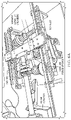
- FIG. 1 is a plan view of one exemplary embodiment of a passive variable stiffness device
- FIG. 2 is a perspective view of the exemplary device of FIG. 1 ;
- FIG. 3A is a schematic plan view representing an exemplary embodiment of a passive variable stiffness device, where certain components have been omitted for clarity;
- FIGS. 3B and 3C are schematic elevation views of the exemplary passive variable stiffness device of FIG. 3A ;
- FIG. 4 is a schematic plan view illustrating variable diameter cylinders for use in an exemplary embodiment of a passive variable stiffness device
- FIG. 5 graphically represents top plate force versus displacement for an exemplary embodiment of a passive variable stiffness device
- FIGS. 6A-6C depict a prototype of one exemplary passive variable stiffness device, via which motion of the various components thereof may be better understood;
- FIG. 7 graphically represents experimental top plate force versus theoretical top plate force for an exemplary embodiment of a passive variable stiffness device.
- FIG. 8 is a schematic plan view representing an alternative exemplary embodiment of a passive variable stiffness device, where certain components have again been omitted for clarity.
- FIGS. 1-2 One exemplary embodiment of a passive variable stiffness device 5 (hereinafter also just “device” for brevity) is represented in FIGS. 1-2 .
- the exemplary device includes a number of components, such as a base plate 10 to which a number of other device components may be directly or indirectly mounted; an identical pair of spaced apart variable diameter cylinders 15 , 20 ; an assembly of two constant force springs 25 , 30 that resides in the space between the variable diameter cylinders 15 , 20 ; a lead screw 35 and associated lead screw gear train 40 that imparts linear motion to the constant force spring assembly; a top plate 50 (see FIG.
- top plate linear guide assemblies 55 a , 55 b an associated pair of spaced apart top plate linear guide assemblies 55 a , 55 b ; a cylinder gear train 60 that is driven by a corresponding cylinder gear rack 65 that is coupled to the top plate 50 ; a lead screw gear rack 45 that is also coupled to the top plate 50 and drives the lead screw gear train 40 ; and a pair of pulleys 70 a , 70 b that are coupled to respective ones of the variable diameter cylinders 15 , 20 and are coupled to one another by a drive belt 75 (see FIG. 2 ).
- One or more other components may also be present, such as but not limited to, other components used to convert between rotational and translational motion, and torque and force, within the device 5 .
- a reference X-Y coordinate system is shown in FIG. 1 for facilitating an understanding of any subsequently described device component orientation and/or motion.
- each of the variable diameter cylinders 15 , 20 (hereinafter also just “cylinder” individually or “cylinders” collectively for brevity) is constant over a portion of its length and variable over the remaining portion of its length.
- half of the length of each cylinder is of constant diameter and the remaining half of the length of each cylinder is of varying in diameter.
- variable diameter cylinders 15 , 20 are aligned so that the longitudinal axes thereof are parallel to the Y-axis, and also substantially parallel to the direction of linear movement of the springs 25 , 30 and substantially perpendicular to the direction of movement of the top plate 50 .
- the variable diameter cylinders 15 , 20 are also arranged in a flipped relationship such that the variable diameter end of one the first cylinder 15 faces the lead screw gear train 40 while the variable diameter end of other the second cylinder 20 faces the cylinder gear train 60 .
- variable diameter cylinders 15 , 20 also results in the constant diameter portion of the first the first cylinder 15 being located substantially across from the variable diameter portion of the second the second cylinder 20 , and vice versa. This arrangement further results in point of diameter transition on each cylinder (i.e., the midpoint in this example) residing at the same position along the Y-axis of the device 5 .
- Each of the variable diameter cylinders 15 , 20 is mounted to the base plate 10 so as to be restrained against linear movement and to be constrained to rotation about only the longitudinal axis thereof.
- Each of the variable diameter cylinders 15 , 20 further includes a circumferential helical groove 80 , 85 that preferably spans the length of the cylinder.
- the constant force springs 25 , 30 located between the variable diameter cylinders 15 , 20 are stacked one on top of the other in this device embodiment.
- the springs 25 , 30 are further arranged so that the front of the first spring 25 faces the first variable diameter the first cylinder 15 , while the front of the second spring 30 faces the second variable diameter the second cylinder 20 .
- a retractable cable 90 , 95 (see FIG. 2 ) is associated with and may be extended from a front portion of each constant force spring 25 , 30 .
- the cable 90 extends from the first spring 25 and is wound around approximately half the length of the first variable diameter the first cylinder 15 .
- the cable 95 extends from the second spring 30 and is wound around approximately half the length of the second variable diameter the second cylinder 20 .
- the wound portions of the cables 90 , 95 reside within the helical grooves 80 , 85 of the respective variable diameter cylinders 15 , 20 .
- the cables 90 , 95 are wound around the respective variable diameter cylinders 15 , 20 starting at the same end of each cylinder (same Y-axis position) and wind toward the center thereof. However, the cables 90 , 95 are wound around the respective cylinders 15 , 20 in opposite directions—i.e., in a clockwise direction relative to one cylinder and in a counterclockwise direction relative to the other cylinder.
- the ending positions of the springs after winding of the cables is the position where the cables intersect the cylinders at substantially the midpoint of the length thereof, which is also a point where the cylinder diameters are equal.
- the assembly of the constant force springs 25 , 30 is mounted on the lead screw 35 , which is operative to move the spring assembly back-and-forth along the Y-axis of the device, which is also substantially parallel to the longitudinal axes of the variable diameter cylinders 15 , 20 .
- a constraint element such as the linear shaft 100 shown, may be provided to prevent rotation of the spring assembly about the lead screw 35 and to further constrain movement of the spring assembly to the direction of the Y-axis.
- pulleys 70 a , 70 b are respectively coupled to substantially aligned ends of the variable diameter cylinders 15 , 20 and are coupled to each other by a belt 75 .
- the pulleys 70 a , 70 b are preferably of like diameter, such that the ratio of the angular displacements between the cylinders 15 , 20 will be 1:1 when the cylinders are caused to be rotated by transmission of a rotating force thereto (as described in more detail below).
- the aforementioned lead screw gear train 40 At the same end of the device 5 near which the belt 75 and pulleys 70 a , 70 b reside is the aforementioned lead screw gear train 40 . Teeth of the lead screw gear train 40 are engaged with complimentary teeth of a superjacent lead screw gear rack 45 , which itself is connected to the overlying top plate 50 . The lead screw gear train 40 is also coupled to and rotates the lead screw 35 that moves the assembly of constant force springs 20 , 25 .
- the aforementioned cylinder gear train 60 resides near the opposite side of the device 5 . Teeth of the cylinder gear train 60 are engaged with complimentary teeth of a superjacent cylinder gear rack 65 , which is also connected to the overlying top plate 50 .
- the cylinder gear train 60 includes a cylinder gear 60 a that is coupled to the first variable diameter cylinder 15 . Consequently, operation of the cylinder gear train 60 results in a rotation of the first variable diameter the first cylinder 15 .
- the top plate 50 is preferably a rigid component and is mounted on the linear guide assemblies 55 a , 55 b that facilitate linear motion of the top plate. Movement of the top plate is constrained to linear motion along the X-axis of the device 5 due to the orientation of the lead screw gear rack 45 and cylinder gear rack 60 , as well as the orientation of the linear guide assemblies 55 a , 55 b . As would be understood by one of skill in the art, the top plate 50 serves as the connection between the device 5 and equipment or some other object, etc., for which the application of vibration isolation is desired.
- the forces of acceleration experienced by the object connected to the top plate 50 are transferred thereby to the device 5 , where they are countered and movement of the object is correspondingly reduced by the restoring force characteristics of the device 5 .
- the shape, size, configuration, etc., of the top plate 50 may be different in other embodiments as dictated by the object to which it will be connected or otherwise.
- the gear trains 40 , 60 operate to control the rotation of the variable diameter cylinders 15 , 20 relative to displacement of the top plate 50 .
- the gear trains 40 , 60 also operate to control the rotation of the variable diameter cylinders 15 , 20 relative to rotation of the lead screw 35 , which in turn, controls the position of the constant force springs 25 , 30 relative to the position of the cables 90 , 95 that are wound about the cylinders.
- the gear trains 40 , 60 further serve to amplify the force imparted to the top plate 50 by the constant force springs 25 , 30 .
- Top plate displacement which is constrained to linear movement—is converted to rotation of the first variable diameter the first cylinder 15 when resulting linear motion of the cylinder gear rack 65 connected to the top plate 50 causes a resulting rotation of the cylinder gear train 60 with which the gear rack is engaged.
- the rotation of the first variable diameter cylinder 15 is then transferred to the second variable diameter the second cylinder 20 via the belt 75 and pulleys 70 a , 70 b.
- the torque that develops about the second variable diameter cylinder 20 as a result of this rotation is transferred back to the first variable diameter cylinder via the combination of the belt 75 and pulleys 70 a , 70 b .
- the total torque on the first variable diameter the first cylinder 15 or the sum of the torques on the first and second variable diameter cylinders 15 , 20 , is then converted to a force on the top plate 50 through the cylinder gear rack 65 and associated cylinder gear train 60 .
- the assembly of the constant force springs 25 , 30 is mounted on the lead screw 35 , and rotation of the lead screw produces a linear movement of the constant force springs along the Y-axis direction of the device and parallel to the longitudinal axes of the variable diameter cylinders 15 , 20 as the cables 90 , 95 extending from the constant force springs wind/unwind about the cylinders.
- the lead screw 35 functions to keep the longitudinal axes of the cables 90 , 95 substantially perpendicular to the longitudinal axes of the variable diameter cylinders 15 , 20 at all times during operation of the device 5 .
- the constant force springs 25 , 30 produce resistive torques on the variable diameter cylinders 15 , 20 that are equal in magnitude but opposite in direction, resulting in static equilibrium of the device.
- linear movement of the top plate in the ⁇ X-direction such as movement caused by seismic activity when the device is installed in a given application, produces a clockwise rotation of one of the cylinders and a counterclockwise rotation of the other cylinder, as well as a winding of one of the cables and an unwinding of the other cable.
- the cable on one cylinder will wind/unwind up the variable diameter, thereby increasing its resistive torque, while the cable on the other cylinder will wind/unwind along a constant diameter, and its resistive torque will remain constant.
- the constant force springs 25 , 30 are driven by the lead screw 35 in the direction of winding/unwinding ( ⁇ Y-direction) to ensure that the cables remain within the helical grooves 80 , 85 in the variable diameter cylinders 15 , 20 .
- the gear trains 40 , 60 at each end of the device 5 are designed to ensure that the constant force springs 25 , 30 are driven at the same rate at which the cables 90 , 95 move along the cylinder lengths as they are wound/unwound.
- variable diameter cylinders 15 , 20 The torques from both of the variable diameter cylinders 15 , 20 are transmitted through the device 5 to the top plate 50 , resulting in a net resistive force being exerted on the top plate in the ⁇ X-direction.
- the net resistive force increases with increasing displacement of the top plate 50 , with the rate of increase depending on the change in diameter of the variable diameter cylinders 15 , 20 . Consequently, an exemplary variable stiffness device may be provided with a wide range of force-displacement characteristics through the design of the variable diameter cylinders.
- an exemplary device can accommodate a large range of isolator displacements by increasing the length of the cables associated with the constant force springs and by increasing the number of times the cables are wrapped around the cylinders (e.g., by decreasing the spacing between the helical grooves), without requiring any significant increase in the size of the device.
- FIG. 3A is a schematic plan view of the exemplary passive variable stiffness device 5 of FIGS. 1-2 , where various components not essential to modeling of device force-displacement characteristics (e.g., top plate, linear guides, etc.) have been omitted for clarity.
- Schematic elevation views of opposite sides of the device of FIG. 3A are respectively presented in FIGS. 3B and 3C , where various components not essential to modeling of device force-displacement characteristics have again been omitted for clarity.
- the total force exerted on the top plate ( 50 ) of the device is the sum of the forces exerted by the cylinder gear rack ( 60 ) and the lead screw rack ( 45 ), which are both connected to the bottom of the top plate, or:
- F plate F cyl + F s ⁇ c ⁇ r ( 1 )
- the force F cyl exerted by the cylinder gear rack is designed to vary with the displacement of the top plate and is, therefore, the primary force of interest in the device.
- the force F scr exerted by the lead screw gear rack is a secondary force generated by driving the constant force springs 25 , 35 along the lead screw 35 .
- the force F scr should be designed to be small relative to F cyl , and will therefore have little significance on the operation of the device. As a result, only the force F cyl will be considered hereafter.
- the force F cyl exerted by the cylinder gear rack on the top plate is equal to the torque T pin generated about the pinion connected to the cylinder gear rack divided by the radius r pin of the pinion, or:
- the torque T pin is the product of the total gear ratio f of the cylinder gear train and the total torque T total generated on the first variable diameter cylinder 15 , or:
- T p ⁇ i ⁇ n f ⁇ T total ( 3 )
- the total gear ratio f of the cylinder gear train is the product of the gear ratios of the individual gear pairs comprising the gear train.
- the total torque T total generated on the first cylinder is the sum of the torque T 1 generated about the first cylinder and the torque T 2 generated about the second cylinder and transferred to the first cylinder through the belt-pulley system ( 70 a , 70 b , 75 ).
- the torque T 1 generated about the first cylinder is equal to the product of the force F s1 from the constant force spring connected to the first cylinder and the radius r c1 (z 1 ).
- the radius r c1 (z 1 ) is the radius of the helical groove around the circumference of the first cylinder within which the cable from the associated constant force spring resides when wound around the first cylinder.
- the radius of the helical groove varies with the cylinder radius as a function of the position z 1 of the helical groove along the longitudinal axis of the first cylinder.
- the torque T 1 is given by:
- T 1 F s ⁇ 1 ⁇ r c ⁇ 1 ⁇ ( z 1 ) ( 4 )
- the torque T 2 generated about the second cylinder is equal to the product of the force F s2 from the constant force spring connected to the second cylinder by the associated cable and the radius r c2 (z 2 ) of the helical groove around the circumference of the second cylinder within which the cable from the associated constant force spring resides when wound around the second cylinder, or:
- T 2 F s ⁇ 2 ⁇ r c ⁇ 2 ⁇ ( z 2 ) ( 5 )
- the two variable diameter cylinders are connected by the belt-pulley system so that the torque T 2 is transferred to the first cylinder, or:
- T 1 ⁇ 2 r p ⁇ 1 r p ⁇ ⁇ 2 ⁇ T 2 ( 6 )
- r p1 is the radius of the pulley attached to the first cylinder
- r p2 is the radius of the pulley attached to the second cylinder
- T 12 is the torque transferred to the first cylinder from the second cylinder through the belt-pulley system. The total torque about the first cylinder is then equal to:
- F plate f r pin ⁇ [ F s ⁇ 1 ⁇ r c ⁇ 1 ⁇ ( z 1 ) + r p ⁇ 1 r p ⁇ ⁇ 2 ⁇ F s ⁇ 2 ⁇ r c ⁇ 2 ⁇ ( z 2 ) ] ( 8 )
- Equation 8 shows that the force on the top plate depends on the radii r c1 (z 1 ) and r c2 (z 2 ) of the helical grooves around the circumferences of the variable diameter cylinders about which the cables from the corresponding constant force springs are wound. Therefore, in order to describe the force on the top plate for any position z of the cables along the length of the cylinders, it is necessary to define the variation in the radii of the helical grooves along the cylinder lengths. To this end, a schematic representation of the variable diameter cylinders 15 , 20 is shown in FIG. 4 . The cylinders are drawn with the same arrangement and orientation shown in FIGS. 1-2 . The assembly of the constant force springs 25 , 30 is again shown to reside between the cylinders 15 , 20 and to be coupled to the lead screw 35 .
- each section of the cylinders has a constant slope that defines the change in radius of the cylinder over the length of the section.
- the slopes of the i th section of the first cylinder and the second cylinder are denoted as m 1 i and m 2 i , respectively, and will be positive if the radius increases with increasing position along the Y-axis.
- the starting radii r 1 and r 2 of the first section of the first cylinder and the second cylinder are also included in the figure.
- the section lengths, slopes, and starting radii can now be used to define the radii of the helical grooves along the circumference of the i th section of the first cylinder and the second cylinder as:
- Equations (9) and (10) can be expressed more generally as:
- Equation 11 defines the radii of the helical grooves in first cylinder and the second cylinder as functions of the positions z 1 and z 2 of the helical grooves along the longitudinal axes of the cylinders, respectively.
- the positions z 1,2 are related to the leads l 1,2 of the helical grooves and the number of rotations ⁇ 1,2 of the cylinders, or:
- Equation 12 the rotation ⁇ 2 of the second cylinder is related to the rotation ⁇ 1 of the first cylinder by the belt-pulley system, or:
- the rotation ⁇ 1 of the first cylinder is related to the rotation ⁇ pin of the pinion connecting the cylinder gear train to the cylinder rack, or:
- ⁇ 1 f ⁇ ⁇ pin ( 14 ) and the rotation ⁇ pin is related to the top plate displacement x plate by:
- Equations 8-15 can be combined to give the force on the top plate F plate as a function of the top plate displacement x plate , or:
- F plate f ⁇ F s r pin ⁇ [ ( r 1 - r 2 ) + ( ⁇ 1 i ⁇ ( m 1 i - 1 - m 2 i - 1 ) ⁇ L i - 1 ) + ( L 2 - ⁇ 1 i ⁇ L i - 1 ) ⁇ ( m 1 i - m 2 i ) ] + f 2 ⁇ F s ⁇ l 2 ⁇ ⁇ ⁇ r pin 2 ⁇ ( m 1 i - m 2 i ) ⁇ x plate ( 16 )
- FIG. 5 A plot of the top plate force vs. displacement for an example passive variable stiffness system is shown in FIG. 5 , where the variable force-displacement characteristics of the device can be observed.
- the force-displacement profile of the device shown in FIG. 5 is characterized by positive tangential stiffness at small and large positive and negative displacements, and zero tangential stiffness in between.
- the force-displacement profile of the device is directly related to slopes of the different sections chosen for the variable diameter cylinders. As a result, various force-displacement profiles are achievable by manufacturing properly shaped variable diameter cylinders.
- FIGS. 6A-6C show the relationship between the motion of the top plate and the motion of the constant force springs.
- the force from the load cell and the position of the actuator were collected using a DAQ system with a sampling rate of 20 Hz.
- the force and position data were used to evaluate the variable force-displacement characteristics of the prototype device.
- a plot of the experimental top plate force versus displacement is shown in FIG. 7 , along with the theoretical force versus displacement predicted from Equation 16. It should be noted that the theoretical prediction includes and additional Coulomb friction term to account for the friction inherent in the experiment.
- FIG. 8 One alternative embodiment of a passive variable stiffness device, where the lead screw of the previously described exemplary embodiments has been removed and replaced with another mechanism for keeping the longitudinal axes of the cables extending from the constant force springs perpendicular to the longitudinal axes of the variable diameter cylinders, is shown in FIG. 8 .
- the lead screw has, more specifically, been replaced with two constant diameter cylinders with variable lead helical grooves encircling their circumferences.
- each variable lead cylinder is paired with one of the variable diameter cylinders, as shown.
- Each pair of variable diameter cylinder and variable lead cylinder are arranged so that their longitudinal axes are parallel.
- Each variable diameter cylinder is then connected to the top plate using a rack-and-pinion (or back-driven ball-screw) with or without a gear train (gear train shown in FIG. 8 ) to convert horizontal linear displacement of the top plate to rotation of the cylinders.
- the belt-pulley system has also been omitted and each cylinder is connected directly to the gear rack.
- the belt-pulley system could also be used as shown and explained relative to the previously described exemplary embodiments.
- each variable lead cylinder has a constant force spring attached to one end thereof. Cables associated with the constant force springs are initially wound around half of the variable lead cylinders and half of the variable diameter cylinders, starting from opposite ends of the cylinders.
- This winding technique is represented in FIG. 8 by the use of thin lines to represent the helical grooves around the circumference of the cylinders and the use of thicker lines to represent cables that have been wound about the cylinders and are residing in some of the helical grooves.
- the cables are again wound in opposite directions about the cylinders resulting in opposing torques on the variable diameter cylinders.
- the cables are wound around the cylinders until they reach the transition point of the variable diameter cylinders—i.e., the point at which the change from a constant diameter to a variable diameter occurs but where the diameters of the variable diameter cylinders are the same.
- the initial torques on the variable diameter cylinders are equal in magnitude but opposite in direction, resulting in static equilibrium of the passive variable stiffness device at the starting position.
- the cables extending from the constant force springs wind/unwind along the cylinder pairs.
- the cable from one cylinder pair winds/unwinds along the length of the variable diameter cylinder with increasing diameter, leading to an increase in the resistive torque on that variable diameter cylinder.
- the cable from the other cylinder pair winds/unwinds along the length of variable diameter cylinder with constant diameter, leading to a constant resistive torque on that variable diameter cylinder.
- the torques on the variable diameter cylinders are transferred as forces to the top plate resulting in a net resistive force on the top plate that increases with increasing displacement of the top plate.
- a variable lead cylinder with an attached constant force spring is paired with each variable diameter cylinder to produce a net resistive force on the top plate that varies with the top plate displacement.
- the cables extending from the constant force springs are initially wound around half of the length of both cylinders in each cylinder pair until they reach the transition point of the variable diameter cylinders.
- the rotation of the variable diameter cylinders will cause rotation of the variable lead cylinders through the tension in the cables of the constant force springs. That is, the cable from the constant force springs constrains the variable diameter cylinders and the variable lead cylinders to have the same circumferential displacement and velocity.
- the rotation of the variable diameter cylinder and the variable lead cylinder will be the same.
- the rotation of the variable diameter cylinder and the variable lead cylinder will be different. Specifically, the cylinder in the pair with the smaller diameter will have higher angular displacement and velocity (i.e., will rotate more) relative to the cylinder with the larger diameter. If the cylinders have helical grooves with the same lead, the difference in the angular displacements of the two cylinders will result in the cable moving further along the longitudinal axis of the cylinder with the smaller diameter relative to the cylinder with the larger diameter.
- variable lead cylinders it is necessary for the variable lead cylinders to have helical grooves with different leads along their lengths. Specifically, where the diameter of the variable lead cylinder is smaller than that of the variable diameter cylinder, the helical groove on the variable lead cylinder should have a shorter lead. Where the diameter of the variable lead cylinder is larger than that of the variable diameter cylinder, the helical groove on the variable lead cylinder should have a longer lead.
- exemplary passive variable stiffness device embodiments described above and represented in the drawing figures include several common mechanical components/assemblies, such as rack-and-pinion assemblies, gear trains, a belt-pulley system, and a lead screw.
- exemplary passive variable stiffness devices may be configured differently while still achieving the same variable force-displacement characteristics.
- the aforementioned rack-and-pinion mechanisms could be replaced by a back-driven ball screw while still maintaining the same functionality of the device.
- the top plate could instead drive each variable diameter cylinder independently using separate rack-and-pinions (or back-driven ball-screws) with or without gear trains in an alternative embodiment.
- the cables associated with the constant force springs could be wound in the opposite direction around the variable diameter cylinders so that the resulting torque assists, instead of resists, the motion of the top plate.
- the device would produce force-displacement characteristics with a negative slope, or passive variable negative stiffness.
- variable diameter cylinders with sections of constant slope could instead be designed with other variations in diameter to produce the desired variable force-displacement characteristics.
Landscapes
- Engineering & Computer Science (AREA)
- General Engineering & Computer Science (AREA)
- Architecture (AREA)
- Environmental & Geological Engineering (AREA)
- Structural Engineering (AREA)
- Acoustics & Sound (AREA)
- Aviation & Aerospace Engineering (AREA)
- Mechanical Engineering (AREA)
- Physics & Mathematics (AREA)
- Emergency Management (AREA)
- Civil Engineering (AREA)
- Business, Economics & Management (AREA)
- Life Sciences & Earth Sciences (AREA)
- General Life Sciences & Earth Sciences (AREA)
- Mining & Mineral Resources (AREA)
- Paleontology (AREA)
- Transmission Devices (AREA)
- Buildings Adapted To Withstand Abnormal External Influences (AREA)
- Vibration Prevention Devices (AREA)
Priority Applications (1)
| Application Number | Priority Date | Filing Date | Title |
|---|---|---|---|
| US17/601,945 US11434973B2 (en) | 2019-04-10 | 2020-04-10 | Passive variable stiffness device for vibration isolation |
Applications Claiming Priority (3)
| Application Number | Priority Date | Filing Date | Title |
|---|---|---|---|
| US201962832092P | 2019-04-10 | 2019-04-10 | |
| PCT/US2020/027841 WO2020210755A1 (en) | 2019-04-10 | 2020-04-10 | Passive variable stiffness device for vibration isolation |
| US17/601,945 US11434973B2 (en) | 2019-04-10 | 2020-04-10 | Passive variable stiffness device for vibration isolation |
Publications (2)
| Publication Number | Publication Date |
|---|---|
| US20220090646A1 US20220090646A1 (en) | 2022-03-24 |
| US11434973B2 true US11434973B2 (en) | 2022-09-06 |
Family
ID=72751491
Family Applications (1)
| Application Number | Title | Priority Date | Filing Date |
|---|---|---|---|
| US17/601,945 Active US11434973B2 (en) | 2019-04-10 | 2020-04-10 | Passive variable stiffness device for vibration isolation |
Country Status (3)
| Country | Link |
|---|---|
| US (1) | US11434973B2 (https=) |
| JP (1) | JP7118482B2 (https=) |
| WO (1) | WO2020210755A1 (https=) |
Families Citing this family (2)
| Publication number | Priority date | Publication date | Assignee | Title |
|---|---|---|---|---|
| WO2024216144A2 (en) * | 2023-04-12 | 2024-10-17 | Ohio University | Variable restoring force isolator |
| CN116851152B (zh) * | 2023-06-26 | 2025-11-21 | 中国电建集团华东勘测设计研究院有限公司 | 具有自主学习能力的超重力离心机振动控制系统 |
Citations (6)
| Publication number | Priority date | Publication date | Assignee | Title |
|---|---|---|---|---|
| US5823307A (en) | 1994-04-04 | 1998-10-20 | Technical Manufacturing Corporation | Stiff actuator active vibration isolation system |
| US20100030384A1 (en) | 2008-07-29 | 2010-02-04 | Technical Manufacturing Corporation | Vibration Isolation System With Design For Offloading Payload Forces Acting on Actuator |
| US20130118098A1 (en) | 2011-11-11 | 2013-05-16 | Michael C. Constantinou | Negative stiffness device and method |
| US20140197299A1 (en) * | 2013-01-16 | 2014-07-17 | Hewlett-Packard Development Company, L.P. | Vibration isolation system |
| US20160082603A1 (en) | 2013-04-24 | 2016-03-24 | Marquette University | Variable Stiffness Actuator With Large Range of Stiffness |
| WO2017177231A1 (en) | 2016-04-08 | 2017-10-12 | Ohio University | Passive variable negative stiffness device and methods of use thereof |
Family Cites Families (1)
| Publication number | Priority date | Publication date | Assignee | Title |
|---|---|---|---|---|
| JP2002130365A (ja) * | 2000-10-30 | 2002-05-09 | Showa Electric Wire & Cable Co Ltd | 免震装置のトリガー機構 |
-
2020
- 2020-04-10 US US17/601,945 patent/US11434973B2/en active Active
- 2020-04-10 WO PCT/US2020/027841 patent/WO2020210755A1/en not_active Ceased
- 2020-04-10 JP JP2021559426A patent/JP7118482B2/ja active Active
Patent Citations (6)
| Publication number | Priority date | Publication date | Assignee | Title |
|---|---|---|---|---|
| US5823307A (en) | 1994-04-04 | 1998-10-20 | Technical Manufacturing Corporation | Stiff actuator active vibration isolation system |
| US20100030384A1 (en) | 2008-07-29 | 2010-02-04 | Technical Manufacturing Corporation | Vibration Isolation System With Design For Offloading Payload Forces Acting on Actuator |
| US20130118098A1 (en) | 2011-11-11 | 2013-05-16 | Michael C. Constantinou | Negative stiffness device and method |
| US20140197299A1 (en) * | 2013-01-16 | 2014-07-17 | Hewlett-Packard Development Company, L.P. | Vibration isolation system |
| US20160082603A1 (en) | 2013-04-24 | 2016-03-24 | Marquette University | Variable Stiffness Actuator With Large Range of Stiffness |
| WO2017177231A1 (en) | 2016-04-08 | 2017-10-12 | Ohio University | Passive variable negative stiffness device and methods of use thereof |
Also Published As
| Publication number | Publication date |
|---|---|
| US20220090646A1 (en) | 2022-03-24 |
| WO2020210755A1 (en) | 2020-10-15 |
| JP2022522536A (ja) | 2022-04-19 |
| JP7118482B2 (ja) | 2022-08-16 |
Similar Documents
| Publication | Publication Date | Title |
|---|---|---|
| US11434973B2 (en) | Passive variable stiffness device for vibration isolation | |
| US7428855B2 (en) | Counter balance system and method with one or more mechanical arms | |
| US9512912B1 (en) | Robot actuator utilizing a differential pulley transmission | |
| US11192241B2 (en) | Variable gravitational torque compensation apparatus and control method therefor | |
| US10233991B2 (en) | Adjustable negative stiffness mechanisms | |
| US10183404B2 (en) | Linear motion device with extending tube for positioning | |
| WO2016185432A1 (en) | A resilient slip friction joint | |
| US20150048234A1 (en) | Vibration-Insulating Device and System | |
| US6899308B2 (en) | Passive gravity-compensating mechanisms | |
| US20240117856A1 (en) | Multi-degree vibration isolation unit | |
| EP3568608B1 (en) | Adjustable negative stiffiness mechanisms | |
| EP2890527B1 (en) | Variable-stiffness actuator with passive disturbance rejection | |
| EP0583868A1 (en) | Vibration damping device | |
| JP5269245B1 (ja) | 構造物の制振装置 | |
| JP3312268B2 (ja) | 軽荷重用免震装置 | |
| JPH11351318A (ja) | 免震装置用ダンパ | |
| US5245807A (en) | Vibration suppressing apparatus for a structure | |
| KR101458303B1 (ko) | 가변 모멘트 아암 기반 하중 보상 유니트 | |
| JP2022522536A5 (https=) | ||
| JP6719326B2 (ja) | 免震機構 | |
| JP2002115418A (ja) | 耐震装置用摩擦ダンパ | |
| JP7422421B2 (ja) | 累積変位計及び制振ダンパー | |
| RU2002140C1 (ru) | Амортизатор | |
| JP7415543B2 (ja) | クリアランス調整機構 | |
| WO2024216144A2 (en) | Variable restoring force isolator |
Legal Events
| Date | Code | Title | Description |
|---|---|---|---|
| AS | Assignment |
Owner name: OHIO UNIVERSITY, OHIO Free format text: ASSIGNMENT OF ASSIGNORS INTEREST;ASSIGNOR:WALSH, KENNETH K., DR.;REEL/FRAME:057724/0373 Effective date: 20190412 |
|
| FEPP | Fee payment procedure |
Free format text: ENTITY STATUS SET TO UNDISCOUNTED (ORIGINAL EVENT CODE: BIG.); ENTITY STATUS OF PATENT OWNER: SMALL ENTITY |
|
| FEPP | Fee payment procedure |
Free format text: ENTITY STATUS SET TO SMALL (ORIGINAL EVENT CODE: SMAL); ENTITY STATUS OF PATENT OWNER: SMALL ENTITY |
|
| STPP | Information on status: patent application and granting procedure in general |
Free format text: DOCKETED NEW CASE - READY FOR EXAMINATION |
|
| STPP | Information on status: patent application and granting procedure in general |
Free format text: NOTICE OF ALLOWANCE MAILED -- APPLICATION RECEIVED IN OFFICE OF PUBLICATIONS |
|
| STPP | Information on status: patent application and granting procedure in general |
Free format text: AWAITING TC RESP., ISSUE FEE NOT PAID |
|
| STPP | Information on status: patent application and granting procedure in general |
Free format text: NOTICE OF ALLOWANCE MAILED -- APPLICATION RECEIVED IN OFFICE OF PUBLICATIONS |
|
| STPP | Information on status: patent application and granting procedure in general |
Free format text: PUBLICATIONS -- ISSUE FEE PAYMENT VERIFIED |
|
| STCF | Information on status: patent grant |
Free format text: PATENTED CASE |
|
| CC | Certificate of correction | ||
| MAFP | Maintenance fee payment |
Free format text: PAYMENT OF MAINTENANCE FEE, 4TH YR, SMALL ENTITY (ORIGINAL EVENT CODE: M2551); ENTITY STATUS OF PATENT OWNER: SMALL ENTITY Year of fee payment: 4 |