US11406357B2 - Cradle apparatus - Google Patents
Cradle apparatus Download PDFInfo
- Publication number
- US11406357B2 US11406357B2 US16/195,291 US201816195291A US11406357B2 US 11406357 B2 US11406357 B2 US 11406357B2 US 201816195291 A US201816195291 A US 201816195291A US 11406357 B2 US11406357 B2 US 11406357B2
- Authority
- US
- United States
- Prior art keywords
- ultrasound diagnostic
- diagnostic apparatus
- cradle
- connector
- guide
- Prior art date
- Legal status (The legal status is an assumption and is not a legal conclusion. Google has not performed a legal analysis and makes no representation as to the accuracy of the status listed.)
- Active, expires
Links
Images


Classifications
-
- A—HUMAN NECESSITIES
- A61—MEDICAL OR VETERINARY SCIENCE; HYGIENE
- A61B—DIAGNOSIS; SURGERY; IDENTIFICATION
- A61B8/00—Diagnosis using ultrasonic, sonic or infrasonic waves
- A61B8/44—Constructional features of the ultrasonic, sonic or infrasonic diagnostic device
- A61B8/4433—Constructional features of the ultrasonic, sonic or infrasonic diagnostic device involving a docking unit
-
- A—HUMAN NECESSITIES
- A61—MEDICAL OR VETERINARY SCIENCE; HYGIENE
- A61B—DIAGNOSIS; SURGERY; IDENTIFICATION
- A61B8/00—Diagnosis using ultrasonic, sonic or infrasonic waves
- A61B8/42—Details of probe positioning or probe attachment to the patient
- A61B8/4209—Details of probe positioning or probe attachment to the patient by using holders, e.g. positioning frames
-
- A—HUMAN NECESSITIES
- A61—MEDICAL OR VETERINARY SCIENCE; HYGIENE
- A61B—DIAGNOSIS; SURGERY; IDENTIFICATION
- A61B8/00—Diagnosis using ultrasonic, sonic or infrasonic waves
- A61B8/44—Constructional features of the ultrasonic, sonic or infrasonic diagnostic device
- A61B8/4405—Device being mounted on a trolley
-
- A—HUMAN NECESSITIES
- A61—MEDICAL OR VETERINARY SCIENCE; HYGIENE
- A61B—DIAGNOSIS; SURGERY; IDENTIFICATION
- A61B8/00—Diagnosis using ultrasonic, sonic or infrasonic waves
- A61B8/44—Constructional features of the ultrasonic, sonic or infrasonic diagnostic device
- A61B8/4411—Device being modular
-
- A—HUMAN NECESSITIES
- A61—MEDICAL OR VETERINARY SCIENCE; HYGIENE
- A61B—DIAGNOSIS; SURGERY; IDENTIFICATION
- A61B8/00—Diagnosis using ultrasonic, sonic or infrasonic waves
- A61B8/44—Constructional features of the ultrasonic, sonic or infrasonic diagnostic device
- A61B8/4427—Device being portable or laptop-like
-
- A—HUMAN NECESSITIES
- A61—MEDICAL OR VETERINARY SCIENCE; HYGIENE
- A61B—DIAGNOSIS; SURGERY; IDENTIFICATION
- A61B8/00—Diagnosis using ultrasonic, sonic or infrasonic waves
- A61B8/56—Details of data transmission or power supply
-
- F—MECHANICAL ENGINEERING; LIGHTING; HEATING; WEAPONS; BLASTING
- F16—ENGINEERING ELEMENTS AND UNITS; GENERAL MEASURES FOR PRODUCING AND MAINTAINING EFFECTIVE FUNCTIONING OF MACHINES OR INSTALLATIONS; THERMAL INSULATION IN GENERAL
- F16M—FRAMES, CASINGS OR BEDS OF ENGINES, MACHINES OR APPARATUS, NOT SPECIFIC TO ENGINES, MACHINES OR APPARATUS PROVIDED FOR ELSEWHERE; STANDS; SUPPORTS
- F16M11/00—Stands or trestles as supports for apparatus or articles placed thereon ; Stands for scientific apparatus such as gravitational force meters
- F16M11/02—Heads
- F16M11/04—Means for attachment of apparatus; Means allowing adjustment of the apparatus relatively to the stand
- F16M11/041—Allowing quick release of the apparatus
-
- F—MECHANICAL ENGINEERING; LIGHTING; HEATING; WEAPONS; BLASTING
- F16—ENGINEERING ELEMENTS AND UNITS; GENERAL MEASURES FOR PRODUCING AND MAINTAINING EFFECTIVE FUNCTIONING OF MACHINES OR INSTALLATIONS; THERMAL INSULATION IN GENERAL
- F16M—FRAMES, CASINGS OR BEDS OF ENGINES, MACHINES OR APPARATUS, NOT SPECIFIC TO ENGINES, MACHINES OR APPARATUS PROVIDED FOR ELSEWHERE; STANDS; SUPPORTS
- F16M11/00—Stands or trestles as supports for apparatus or articles placed thereon ; Stands for scientific apparatus such as gravitational force meters
- F16M11/42—Stands or trestles as supports for apparatus or articles placed thereon ; Stands for scientific apparatus such as gravitational force meters with arrangement for propelling the support stands on wheels
-
- F—MECHANICAL ENGINEERING; LIGHTING; HEATING; WEAPONS; BLASTING
- F16—ENGINEERING ELEMENTS AND UNITS; GENERAL MEASURES FOR PRODUCING AND MAINTAINING EFFECTIVE FUNCTIONING OF MACHINES OR INSTALLATIONS; THERMAL INSULATION IN GENERAL
- F16M—FRAMES, CASINGS OR BEDS OF ENGINES, MACHINES OR APPARATUS, NOT SPECIFIC TO ENGINES, MACHINES OR APPARATUS PROVIDED FOR ELSEWHERE; STANDS; SUPPORTS
- F16M13/00—Other supports for positioning apparatus or articles; Means for steadying hand-held apparatus or articles
- F16M13/005—Other supports for positioning apparatus or articles; Means for steadying hand-held apparatus or articles integral with the apparatus or articles to be supported
-
- A—HUMAN NECESSITIES
- A61—MEDICAL OR VETERINARY SCIENCE; HYGIENE
- A61B—DIAGNOSIS; SURGERY; IDENTIFICATION
- A61B8/00—Diagnosis using ultrasonic, sonic or infrasonic waves
- A61B8/02—Measuring pulse or heart rate
-
- A—HUMAN NECESSITIES
- A61—MEDICAL OR VETERINARY SCIENCE; HYGIENE
- A61B—DIAGNOSIS; SURGERY; IDENTIFICATION
- A61B8/00—Diagnosis using ultrasonic, sonic or infrasonic waves
- A61B8/08—Clinical applications
- A61B8/0866—Clinical applications involving foetal diagnosis; pre-natal or peri-natal diagnosis of the baby
-
- A—HUMAN NECESSITIES
- A61—MEDICAL OR VETERINARY SCIENCE; HYGIENE
- A61B—DIAGNOSIS; SURGERY; IDENTIFICATION
- A61B8/00—Diagnosis using ultrasonic, sonic or infrasonic waves
- A61B8/44—Constructional features of the ultrasonic, sonic or infrasonic diagnostic device
- A61B8/4444—Constructional features of the ultrasonic, sonic or infrasonic diagnostic device related to the probe
Definitions
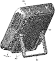
- FIG. 4 is a rear perspective view of the ultrasound diagnostic apparatus
- Bottom portion 21 is the bottom surface of ultrasound diagnostic apparatus 20 . Although not illustrated in FIG. 1 , bottom portion 21 is provided with a connector (see connector 51 of FIG. 6 ). The connector provided in bottom portion 21 is fitted with connector 14 of cradle apparatus 10 when ultrasound diagnostic apparatus 20 is mounted in cradle apparatus 10 .
- Ultrasound diagnostic apparatus 20 is mounted in cradle apparatus 10 by housing variable stand 43 . That is, when variable stand 43 is in the state illustrated in FIG. 4 , ultrasound diagnostic apparatus 20 can be mounted in cradle apparatus 10 .
- a plurality of connectors may be provided.
- ultrasound probes of multiple types may be connected to the cradle apparatus, for example.
- the operator of ultrasound diagnostic apparatus 20 can selectively use a desired ultrasound probe from among multiple types of ultrasound probes.
Landscapes
- Health & Medical Sciences (AREA)
- Life Sciences & Earth Sciences (AREA)
- Engineering & Computer Science (AREA)
- Medical Informatics (AREA)
- Surgery (AREA)
- Pathology (AREA)
- Radiology & Medical Imaging (AREA)
- Biophysics (AREA)
- Biomedical Technology (AREA)
- Heart & Thoracic Surgery (AREA)
- Physics & Mathematics (AREA)
- Molecular Biology (AREA)
- Nuclear Medicine, Radiotherapy & Molecular Imaging (AREA)
- Animal Behavior & Ethology (AREA)
- General Health & Medical Sciences (AREA)
- Public Health (AREA)
- Veterinary Medicine (AREA)
- General Engineering & Computer Science (AREA)
- Mechanical Engineering (AREA)
- Computer Networks & Wireless Communication (AREA)
- Ultra Sonic Daignosis Equipment (AREA)
Abstract
Description
Claims (13)
Applications Claiming Priority (3)
| Application Number | Priority Date | Filing Date | Title |
|---|---|---|---|
| JPJP2017-253718 | 2017-12-28 | ||
| JP2017253718A JP7184512B2 (en) | 2017-12-28 | 2017-12-28 | Cradle device |
| JP2017-253718 | 2017-12-28 |
Publications (2)
| Publication Number | Publication Date |
|---|---|
| US20190200958A1 US20190200958A1 (en) | 2019-07-04 |
| US11406357B2 true US11406357B2 (en) | 2022-08-09 |
Family
ID=67058738
Family Applications (1)
| Application Number | Title | Priority Date | Filing Date |
|---|---|---|---|
| US16/195,291 Active 2040-02-09 US11406357B2 (en) | 2017-12-28 | 2018-11-19 | Cradle apparatus |
Country Status (3)
| Country | Link |
|---|---|
| US (1) | US11406357B2 (en) |
| JP (1) | JP7184512B2 (en) |
| CN (1) | CN110005908A (en) |
Cited By (1)
| Publication number | Priority date | Publication date | Assignee | Title |
|---|---|---|---|---|
| JP7184512B2 (en) | 2017-12-28 | 2022-12-06 | コニカミノルタ株式会社 | Cradle device |
Families Citing this family (3)
| Publication number | Priority date | Publication date | Assignee | Title |
|---|---|---|---|---|
| JP7367537B2 (en) * | 2020-01-23 | 2023-10-24 | コニカミノルタ株式会社 | Ultrasound diagnostic equipment |
| JP7661867B2 (en) * | 2021-11-09 | 2025-04-15 | コニカミノルタ株式会社 | Ultrasound diagnostic equipment |
| WO2025023398A1 (en) * | 2023-07-25 | 2025-01-30 | 삼성메디슨 주식회사 | Buffer device and ultrasonic diagnostic device assembly comprising same |
Citations (15)
| Publication number | Priority date | Publication date | Assignee | Title |
|---|---|---|---|---|
| JPH11155005A (en) | 1997-11-20 | 1999-06-08 | Kojima Press Co Ltd | Device for preventing portable telephone set from being left in automobile |
| JPH11177670A (en) | 1997-12-08 | 1999-07-02 | Kojima Press Co Ltd | Connector mechanism |
| US20020143256A1 (en) * | 1999-05-04 | 2002-10-03 | Sonosite, Inc. | Mobile ultrasound diagnostic instrument and docking stand |
| CN1421088A (en) | 2000-03-31 | 2003-05-28 | 奥林奇私人通讯服务有限公司 | Support for mobile terminal |
| CN2872644Y (en) * | 2006-03-21 | 2007-02-21 | 中山华帝燃具股份有限公司 | Safety protecter for power-supply interface |
| CN101271349A (en) | 2007-03-22 | 2008-09-24 | 研华股份有限公司 | medical assistant computer |
| JP2009200799A (en) | 2008-02-21 | 2009-09-03 | Sony Computer Entertainment Inc | Stand and electronic device |
| US20090270727A1 (en) * | 2008-04-29 | 2009-10-29 | Zhensong Zhao | Docking station and ultrasonic diagnostic system |
| US20110077557A1 (en) * | 2009-09-29 | 2011-03-31 | Medicis Technologies Corporation | Medical ultrasound device with liquid dispensing device coupled to a therapy head |
| US8767396B2 (en) * | 2011-04-06 | 2014-07-01 | Panasonic Corporation | Extension device and information processing system including the same |
| JP2015008796A (en) | 2013-06-27 | 2015-01-19 | 日立アロカメディカル株式会社 | Ultrasonic diagnostic equipment |
| JP3196455U (en) | 2014-12-12 | 2015-03-12 | 株式会社共栄商事 | Tablet PC floor stand |
| JP2015515312A (en) | 2012-03-26 | 2015-05-28 | テラテク・コーポレーシヨン | Tablet ultrasound system |
| US20150190114A1 (en) * | 2012-09-28 | 2015-07-09 | Hitachi Aloka Medical, Ltd. | Portable ultrasound imaging apparatus |
| US10019034B2 (en) * | 2012-03-14 | 2018-07-10 | Popsockets Llc | Docking connector platform for mobile electronic devices |
Family Cites Families (5)
| Publication number | Priority date | Publication date | Assignee | Title |
|---|---|---|---|---|
| JPH11338578A (en) * | 1998-05-29 | 1999-12-10 | Toshiba Corp | Electronic device system and expansion device for expanding functions of electronic device |
| JP3790918B2 (en) * | 1999-04-30 | 2006-06-28 | オリンパス株式会社 | Ultrasonic surgery system |
| JP6031312B2 (en) | 2012-09-28 | 2016-11-24 | 株式会社日立製作所 | Portable ultrasound imaging device |
| RU2547959C1 (en) * | 2014-06-04 | 2015-04-10 | ООО "Рэй Системс" | Portable medical ultrasonic scanner |
| JP7184512B2 (en) | 2017-12-28 | 2022-12-06 | コニカミノルタ株式会社 | Cradle device |
-
2017
- 2017-12-28 JP JP2017253718A patent/JP7184512B2/en active Active
-
2018
- 2018-11-19 US US16/195,291 patent/US11406357B2/en active Active
- 2018-12-25 CN CN201811589547.4A patent/CN110005908A/en active Pending
Patent Citations (17)
| Publication number | Priority date | Publication date | Assignee | Title |
|---|---|---|---|---|
| JPH11155005A (en) | 1997-11-20 | 1999-06-08 | Kojima Press Co Ltd | Device for preventing portable telephone set from being left in automobile |
| JPH11177670A (en) | 1997-12-08 | 1999-07-02 | Kojima Press Co Ltd | Connector mechanism |
| US20020143256A1 (en) * | 1999-05-04 | 2002-10-03 | Sonosite, Inc. | Mobile ultrasound diagnostic instrument and docking stand |
| CN1421088A (en) | 2000-03-31 | 2003-05-28 | 奥林奇私人通讯服务有限公司 | Support for mobile terminal |
| CN2872644Y (en) * | 2006-03-21 | 2007-02-21 | 中山华帝燃具股份有限公司 | Safety protecter for power-supply interface |
| CN101271349A (en) | 2007-03-22 | 2008-09-24 | 研华股份有限公司 | medical assistant computer |
| CN101271349B (en) * | 2007-03-22 | 2010-05-26 | 研华股份有限公司 | medical assistant computer |
| JP2009200799A (en) | 2008-02-21 | 2009-09-03 | Sony Computer Entertainment Inc | Stand and electronic device |
| CN101569537A (en) | 2008-04-29 | 2009-11-04 | Ge医疗系统环球技术有限公司 | Docking station and ultrasonic diagnosis system |
| US20090270727A1 (en) * | 2008-04-29 | 2009-10-29 | Zhensong Zhao | Docking station and ultrasonic diagnostic system |
| US20110077557A1 (en) * | 2009-09-29 | 2011-03-31 | Medicis Technologies Corporation | Medical ultrasound device with liquid dispensing device coupled to a therapy head |
| US8767396B2 (en) * | 2011-04-06 | 2014-07-01 | Panasonic Corporation | Extension device and information processing system including the same |
| US10019034B2 (en) * | 2012-03-14 | 2018-07-10 | Popsockets Llc | Docking connector platform for mobile electronic devices |
| JP2015515312A (en) | 2012-03-26 | 2015-05-28 | テラテク・コーポレーシヨン | Tablet ultrasound system |
| US20150190114A1 (en) * | 2012-09-28 | 2015-07-09 | Hitachi Aloka Medical, Ltd. | Portable ultrasound imaging apparatus |
| JP2015008796A (en) | 2013-06-27 | 2015-01-19 | 日立アロカメディカル株式会社 | Ultrasonic diagnostic equipment |
| JP3196455U (en) | 2014-12-12 | 2015-03-12 | 株式会社共栄商事 | Tablet PC floor stand |
Non-Patent Citations (4)
| Title |
|---|
| CNIPA, Office Action for the corresponding Chinese Patent Application No. 201811589547.4, dated Jun. 17, 2020, with English translation. |
| JPO, Office Action for the corresponding Japanese Patent Application No. 2017-253718, dated Dec. 21, 2021, with English translation. |
| JPO, Office Action for the corresponding Japanese Patent Application No. 2017-253718, dated Jul. 13, 2021, with English translation. |
| JPO, Office Action for the corresponding Japanese Patent Application No. 2017-253718, dated May 24, 2022, with English translation. |
Cited By (1)
| Publication number | Priority date | Publication date | Assignee | Title |
|---|---|---|---|---|
| JP7184512B2 (en) | 2017-12-28 | 2022-12-06 | コニカミノルタ株式会社 | Cradle device |
Also Published As
| Publication number | Publication date |
|---|---|
| CN110005908A (en) | 2019-07-12 |
| US20190200958A1 (en) | 2019-07-04 |
| JP7184512B2 (en) | 2022-12-06 |
| JP2019118463A (en) | 2019-07-22 |
Similar Documents
| Publication | Publication Date | Title |
|---|---|---|
| US11406357B2 (en) | Cradle apparatus | |
| US6560094B2 (en) | Mounting device for a monitor, a flat monitor with such a mounting device, and an assembly of a flat monitor, a drawer and a computer | |
| US20120182709A1 (en) | Support arm and image display device | |
| US20070238922A1 (en) | Endoscope shape detecting device | |
| EP2374441A2 (en) | Siderail accessory module | |
| US5941824A (en) | Ultrasonic diagnostic apparatus having a patient-use monitor | |
| CN104840216A (en) | Ultrasound diagnosis apparatus having plurality of display units | |
| JP2006521151A (en) | Remote wireless control apparatus and method for ultrasonic equipment | |
| JP7661867B2 (en) | Ultrasound diagnostic equipment | |
| KR102731223B1 (en) | Display Device | |
| US20070086154A1 (en) | Auxiliary display system | |
| EP3876505A1 (en) | Terminal case, gripping device and information processing device | |
| CN114886577A (en) | Portable endoscope trolley | |
| JP2002132173A (en) | Display device | |
| US20160190739A1 (en) | Medical module connection base and medical module expansion system | |
| JP2828110B2 (en) | Endoscope inspection table | |
| JP2015104647A (en) | Probe holder and ultrasonic image diagnostic apparatus | |
| JP5872924B2 (en) | Cart for portable ultrasonic diagnostic equipment, portable ultrasonic unit | |
| JP2019080785A (en) | Biological information measurement device and system | |
| US20210228183A1 (en) | Diagnostic ultrasound apparatus | |
| JP2004329761A (en) | Endoscopic equipment | |
| JP2000135194A (en) | Endoscope shape detector | |
| CN222883848U (en) | Electronic equipment | |
| CN100508871C (en) | Endoscope shape detecting device | |
| CN222514664U (en) | Medical service device |
Legal Events
| Date | Code | Title | Description |
|---|---|---|---|
| AS | Assignment |
Owner name: KONICA MINOLTA, INC., JAPAN Free format text: ASSIGNMENT OF ASSIGNORS INTEREST;ASSIGNORS:SHIRAISHI, TAKAHIKO;CHIHARA, TATSUSHI;NOGUCHI, SHINYA;SIGNING DATES FROM 20181031 TO 20181101;REEL/FRAME:047547/0048 |
|
| FEPP | Fee payment procedure |
Free format text: ENTITY STATUS SET TO UNDISCOUNTED (ORIGINAL EVENT CODE: BIG.); ENTITY STATUS OF PATENT OWNER: LARGE ENTITY |
|
| STPP | Information on status: patent application and granting procedure in general |
Free format text: NON FINAL ACTION MAILED |
|
| STPP | Information on status: patent application and granting procedure in general |
Free format text: RESPONSE TO NON-FINAL OFFICE ACTION ENTERED AND FORWARDED TO EXAMINER |
|
| STPP | Information on status: patent application and granting procedure in general |
Free format text: FINAL REJECTION MAILED |
|
| STPP | Information on status: patent application and granting procedure in general |
Free format text: RESPONSE AFTER FINAL ACTION FORWARDED TO EXAMINER |
|
| STPP | Information on status: patent application and granting procedure in general |
Free format text: ADVISORY ACTION MAILED |
|
| STPP | Information on status: patent application and granting procedure in general |
Free format text: DOCKETED NEW CASE - READY FOR EXAMINATION |
|
| STPP | Information on status: patent application and granting procedure in general |
Free format text: NON FINAL ACTION MAILED |
|
| STPP | Information on status: patent application and granting procedure in general |
Free format text: RESPONSE TO NON-FINAL OFFICE ACTION ENTERED AND FORWARDED TO EXAMINER |
|
| STPP | Information on status: patent application and granting procedure in general |
Free format text: NOTICE OF ALLOWANCE MAILED -- APPLICATION RECEIVED IN OFFICE OF PUBLICATIONS |
|
| STPP | Information on status: patent application and granting procedure in general |
Free format text: AWAITING TC RESP., ISSUE FEE NOT PAID |
|
| STPP | Information on status: patent application and granting procedure in general |
Free format text: NOTICE OF ALLOWANCE MAILED -- APPLICATION RECEIVED IN OFFICE OF PUBLICATIONS |
|
| STCF | Information on status: patent grant |
Free format text: PATENTED CASE |