JP7184512B2 - Cradle device - Google Patents
Cradle device Download PDFInfo
- Publication number
- JP7184512B2 JP7184512B2 JP2017253718A JP2017253718A JP7184512B2 JP 7184512 B2 JP7184512 B2 JP 7184512B2 JP 2017253718 A JP2017253718 A JP 2017253718A JP 2017253718 A JP2017253718 A JP 2017253718A JP 7184512 B2 JP7184512 B2 JP 7184512B2
- Authority
- JP
- Japan
- Prior art keywords
- ultrasonic diagnostic
- diagnostic apparatus
- cradle device
- connector
- guide
- Prior art date
- Legal status (The legal status is an assumption and is not a legal conclusion. Google has not performed a legal analysis and makes no representation as to the accuracy of the status listed.)
- Active
Links
- 239000000523 sample Substances 0.000 claims description 9
- 238000002604 ultrasonography Methods 0.000 claims description 9
- 239000000463 material Substances 0.000 description 2
- 230000000994 depressogenic effect Effects 0.000 description 1
- 238000003745 diagnosis Methods 0.000 description 1
- 238000010586 diagram Methods 0.000 description 1
- 230000001605 fetal effect Effects 0.000 description 1
- 239000004973 liquid crystal related substance Substances 0.000 description 1
Images


Classifications
-
- A—HUMAN NECESSITIES
- A61—MEDICAL OR VETERINARY SCIENCE; HYGIENE
- A61B—DIAGNOSIS; SURGERY; IDENTIFICATION
- A61B8/00—Diagnosis using ultrasonic, sonic or infrasonic waves
- A61B8/44—Constructional features of the ultrasonic, sonic or infrasonic diagnostic device
- A61B8/4433—Constructional features of the ultrasonic, sonic or infrasonic diagnostic device involving a docking unit
-
- A—HUMAN NECESSITIES
- A61—MEDICAL OR VETERINARY SCIENCE; HYGIENE
- A61B—DIAGNOSIS; SURGERY; IDENTIFICATION
- A61B8/00—Diagnosis using ultrasonic, sonic or infrasonic waves
- A61B8/44—Constructional features of the ultrasonic, sonic or infrasonic diagnostic device
- A61B8/4405—Device being mounted on a trolley
-
- A—HUMAN NECESSITIES
- A61—MEDICAL OR VETERINARY SCIENCE; HYGIENE
- A61B—DIAGNOSIS; SURGERY; IDENTIFICATION
- A61B8/00—Diagnosis using ultrasonic, sonic or infrasonic waves
- A61B8/42—Details of probe positioning or probe attachment to the patient
- A61B8/4209—Details of probe positioning or probe attachment to the patient by using holders, e.g. positioning frames
-
- A—HUMAN NECESSITIES
- A61—MEDICAL OR VETERINARY SCIENCE; HYGIENE
- A61B—DIAGNOSIS; SURGERY; IDENTIFICATION
- A61B8/00—Diagnosis using ultrasonic, sonic or infrasonic waves
- A61B8/44—Constructional features of the ultrasonic, sonic or infrasonic diagnostic device
- A61B8/4411—Device being modular
-
- A—HUMAN NECESSITIES
- A61—MEDICAL OR VETERINARY SCIENCE; HYGIENE
- A61B—DIAGNOSIS; SURGERY; IDENTIFICATION
- A61B8/00—Diagnosis using ultrasonic, sonic or infrasonic waves
- A61B8/44—Constructional features of the ultrasonic, sonic or infrasonic diagnostic device
- A61B8/4427—Device being portable or laptop-like
-
- A—HUMAN NECESSITIES
- A61—MEDICAL OR VETERINARY SCIENCE; HYGIENE
- A61B—DIAGNOSIS; SURGERY; IDENTIFICATION
- A61B8/00—Diagnosis using ultrasonic, sonic or infrasonic waves
- A61B8/44—Constructional features of the ultrasonic, sonic or infrasonic diagnostic device
- A61B8/4444—Constructional features of the ultrasonic, sonic or infrasonic diagnostic device related to the probe
-
- A—HUMAN NECESSITIES
- A61—MEDICAL OR VETERINARY SCIENCE; HYGIENE
- A61B—DIAGNOSIS; SURGERY; IDENTIFICATION
- A61B8/00—Diagnosis using ultrasonic, sonic or infrasonic waves
- A61B8/56—Details of data transmission or power supply
-
- F—MECHANICAL ENGINEERING; LIGHTING; HEATING; WEAPONS; BLASTING
- F16—ENGINEERING ELEMENTS AND UNITS; GENERAL MEASURES FOR PRODUCING AND MAINTAINING EFFECTIVE FUNCTIONING OF MACHINES OR INSTALLATIONS; THERMAL INSULATION IN GENERAL
- F16M—FRAMES, CASINGS OR BEDS OF ENGINES, MACHINES OR APPARATUS, NOT SPECIFIC TO ENGINES, MACHINES OR APPARATUS PROVIDED FOR ELSEWHERE; STANDS; SUPPORTS
- F16M11/00—Stands or trestles as supports for apparatus or articles placed thereon ; Stands for scientific apparatus such as gravitational force meters
- F16M11/02—Heads
- F16M11/04—Means for attachment of apparatus; Means allowing adjustment of the apparatus relatively to the stand
- F16M11/041—Allowing quick release of the apparatus
-
- F—MECHANICAL ENGINEERING; LIGHTING; HEATING; WEAPONS; BLASTING
- F16—ENGINEERING ELEMENTS AND UNITS; GENERAL MEASURES FOR PRODUCING AND MAINTAINING EFFECTIVE FUNCTIONING OF MACHINES OR INSTALLATIONS; THERMAL INSULATION IN GENERAL
- F16M—FRAMES, CASINGS OR BEDS OF ENGINES, MACHINES OR APPARATUS, NOT SPECIFIC TO ENGINES, MACHINES OR APPARATUS PROVIDED FOR ELSEWHERE; STANDS; SUPPORTS
- F16M11/00—Stands or trestles as supports for apparatus or articles placed thereon ; Stands for scientific apparatus such as gravitational force meters
- F16M11/42—Stands or trestles as supports for apparatus or articles placed thereon ; Stands for scientific apparatus such as gravitational force meters with arrangement for propelling the support stands on wheels
-
- F—MECHANICAL ENGINEERING; LIGHTING; HEATING; WEAPONS; BLASTING
- F16—ENGINEERING ELEMENTS AND UNITS; GENERAL MEASURES FOR PRODUCING AND MAINTAINING EFFECTIVE FUNCTIONING OF MACHINES OR INSTALLATIONS; THERMAL INSULATION IN GENERAL
- F16M—FRAMES, CASINGS OR BEDS OF ENGINES, MACHINES OR APPARATUS, NOT SPECIFIC TO ENGINES, MACHINES OR APPARATUS PROVIDED FOR ELSEWHERE; STANDS; SUPPORTS
- F16M13/00—Other supports for positioning apparatus or articles; Means for steadying hand-held apparatus or articles
- F16M13/005—Other supports for positioning apparatus or articles; Means for steadying hand-held apparatus or articles integral with the apparatus or articles to be supported
-
- A—HUMAN NECESSITIES
- A61—MEDICAL OR VETERINARY SCIENCE; HYGIENE
- A61B—DIAGNOSIS; SURGERY; IDENTIFICATION
- A61B8/00—Diagnosis using ultrasonic, sonic or infrasonic waves
- A61B8/02—Measuring pulse or heart rate
-
- A—HUMAN NECESSITIES
- A61—MEDICAL OR VETERINARY SCIENCE; HYGIENE
- A61B—DIAGNOSIS; SURGERY; IDENTIFICATION
- A61B8/00—Diagnosis using ultrasonic, sonic or infrasonic waves
- A61B8/08—Clinical applications
- A61B8/0866—Clinical applications involving foetal diagnosis; pre-natal or peri-natal diagnosis of the baby
Landscapes
- Health & Medical Sciences (AREA)
- Life Sciences & Earth Sciences (AREA)
- Engineering & Computer Science (AREA)
- Medical Informatics (AREA)
- Surgery (AREA)
- Pathology (AREA)
- Radiology & Medical Imaging (AREA)
- Biophysics (AREA)
- Biomedical Technology (AREA)
- Heart & Thoracic Surgery (AREA)
- Physics & Mathematics (AREA)
- Molecular Biology (AREA)
- Nuclear Medicine, Radiotherapy & Molecular Imaging (AREA)
- Animal Behavior & Ethology (AREA)
- General Health & Medical Sciences (AREA)
- Public Health (AREA)
- Veterinary Medicine (AREA)
- General Engineering & Computer Science (AREA)
- Mechanical Engineering (AREA)
- Computer Networks & Wireless Communication (AREA)
- Ultra Sonic Daignosis Equipment (AREA)
Description
本発明は、超音波診断装置を着脱可能に支持するクレードル装置に関する。 The present invention relates to a cradle device that detachably supports an ultrasonic diagnostic apparatus.
従来、超音波探触子にて生体等の被検体に対して超音波の送受信を行い、受信した超音波から得られた信号に基づいて超音波画像データを生成し、これに基づく超音波画像を画像表示装置に表示する超音波診断装置が知られている。このような装置による超音波診断は、簡単な操作で心臓の拍動や胎児の動き等の被検体の様子がリアルタイムで得られ、かつ非侵襲で安全性が高いため、繰り返して実施することができる。また、近年では、小型で携帯が可能な超音波診断装置が実用化されており、持ち運び等が容易になっている(例えば、特許文献1参照)。 Conventionally, ultrasonic waves are transmitted and received to and from a subject such as a living body using an ultrasonic probe, and ultrasonic image data is generated based on signals obtained from the received ultrasonic waves, and ultrasonic images based on this are generated. is known on an image display device. Ultrasound diagnosis using such a device can be performed repeatedly because it is possible to obtain the state of the subject such as the heartbeat and fetal movement in real time with simple operation, and it is non-invasive and highly safe. can. Moreover, in recent years, a compact and portable ultrasonic diagnostic apparatus has been put to practical use, and it is easy to carry around (see, for example, Patent Document 1).
しかしながら、例えば、携帯可能な超音波診断装置を病室等で固定的に使用したい場合に、超音波診断装置を着脱可能に支持するクレードル装置はこれまで提案されていない。 However, no cradle device has been proposed so far for detachably supporting a portable ultrasonic diagnostic apparatus, for example, when it is desired to use the ultrasonic diagnostic apparatus fixedly in a hospital room or the like.
本発明の目的は、超音波診断装置を容易に着脱可能に支持するクレードル装置を提供することを目的とする。 SUMMARY OF THE INVENTION An object of the present invention is to provide a cradle device that supports an ultrasonic diagnostic apparatus in an easily detachable manner.
本発明に係るクレードル装置は、
超音波診断装置を着脱可能に支持するクレードル装置であって、
前記超音波診断装置の底部を支持する基部と、
前記基部から、前記超音波診断装置の着脱方向に沿って伸び、前記超音波診断装置の表示装置が形成されている前部とは反対側の背部を支持する背部支持部と、
前記超音波診断装置の前記背部に設けられているレールと嵌合し、前記超音波診断装置を前記着脱方向に沿って摺動可能にする、前記背部支持部に設けられたガイドと、
を有し、
前記レールは前記背部を支持する可変スタンドを構成し、前記可変スタンドは前記背部に収納した閉位置と前記背部から起立した開位置とに移動可能であり、
前記ガイドは、第1のガイドと、前記第1のガイドと対向する第2のガイドと、を含み、
前記第1のガイドと前記第2のガイドは、前記可変スタンドを構成する前記レールが前記第1のガイドと前記第2のガイドとで形成される空間に挿入された状態において、前記第1のガイドと前記第2のガイドとが対向する方向に前記超音波診断装置が移動することを制限するように構成されている。
また、本発明に係るクレードル装置は、
超音波診断装置を着脱可能に支持するクレードル装置であって、
前記超音波診断装置の底部を支持する基部と、
前記基部から、前記超音波診断装置の着脱方向に沿って伸び、前記超音波診断装置の表示装置が形成されている前部とは反対側の背部を支持する背部支持部と、
前記超音波診断装置の前記背部に設けられているレールと嵌合し、前記超音波診断装置を前記着脱方向に沿って摺動可能にする、前記背部支持部に設けられたガイドと、
を有し、
前記背部支持部には、前記超音波診断装置が装着されたとき、前記超音波診断装置の前記背部に設けられた電源コネクタに外部電源が接続されないよう、前記電源コネクタを隠すパネルが設けられている。
A cradle device according to the present invention includes:
A cradle device for detachably supporting an ultrasound diagnostic device,
a base supporting the bottom of the ultrasonic diagnostic apparatus;
a back supporting portion extending from the base along the attachment/detachment direction of the ultrasonic diagnostic apparatus and supporting the back on the side opposite to the front portion of the ultrasonic diagnostic apparatus where the display device is formed;
a guide provided on the back supporting portion that engages with a rail provided on the back of the ultrasonic diagnostic apparatus to allow the ultrasonic diagnostic apparatus to slide along the attachment/detachment direction;
has
The rail constitutes a variable stand that supports the back, and the variable stand is movable between a closed position stored in the back and an open position standing from the back,
The guide includes a first guide and a second guide facing the first guide,
The first guide and the second guide are in a state in which the rail constituting the variable stand is inserted into the space formed by the first guide and the second guide. It is configured to restrict movement of the ultrasonic diagnostic apparatus in a direction in which the guide and the second guide face each other.
Further, the cradle device according to the present invention is
A cradle device for detachably supporting an ultrasound diagnostic device,
a base supporting the bottom of the ultrasonic diagnostic apparatus;
a back supporting portion extending from the base along the attachment/detachment direction of the ultrasonic diagnostic apparatus and supporting the back on the side opposite to the front portion of the ultrasonic diagnostic apparatus where the display device is formed;
a guide provided on the back supporting portion that engages with a rail provided on the back of the ultrasonic diagnostic apparatus to allow the ultrasonic diagnostic apparatus to slide along the attachment/detachment direction;
has
The back supporting portion is provided with a panel that hides the power connector provided on the back of the ultrasonic diagnostic apparatus so that an external power supply is not connected to the power connector when the ultrasonic diagnostic apparatus is attached. there is
本発明によれば、超音波診断装置を容易に着脱可能に支持することができる。 According to the present invention, an ultrasonic diagnostic apparatus can be easily detachably supported.
以下、本発明の実施の形態を、図面を参照して説明する。 BEST MODE FOR CARRYING OUT THE INVENTION Hereinafter, embodiments of the present invention will be described with reference to the drawings.
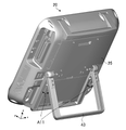
図1は、本発明の実施の形態に係るクレードル装置10を示した斜視図である。図1には、クレードル装置10に着脱される携帯型の超音波診断装置20も示してある。以下では、クレードル装置10および超音波診断装置20に対し、図1に示すx、y、z軸の直交座標系を設定する。また、図1において、+y軸方向がクレードル装置10および超音波診断装置20の前方、-y軸方向がクレードル装置10および超音波診断装置20の後方とする。
FIG. 1 is a perspective view showing a
超音波診断装置20は、クレードル装置10の上方から、クレードル装置10に装着される。例えば、超音波診断装置20は、図1に示す矢印A1方向(-z軸方向)に向ってクレードル装置10に押し込まれることにより、クレードル装置10に装着される。
The ultrasonic
図2は、超音波診断装置20がクレードル装置10に装着された状態を示した斜視図である。図2において、図1と同じものには同じ符号が付してある。上記したように、超音波診断装置20は、クレードル装置10の上方から(図1に示す状態から)、クレードル装置10に押し込まれることにより、図2に示すように、クレードル装置10に装着される。
FIG. 2 is a perspective view showing a state in which the ultrasonic
図1の説明に戻る。クレードル装置10に装着された超音波診断装置20は、クレードル装置10の上方に持ち上げられることにより、クレードル装置10から取り外される。例えば、クレードル装置10に装着された超音波診断装置20は、図1に示す矢印A2方向(+z軸方向)に持ち上げられることにより、クレードル装置10から取り外される。
Returning to the description of FIG. The ultrasonic
クレードル装置10は、例えば、カートに固定される。従って、カートに固定されたクレードル装置10に超音波診断装置20を装着すると、超音波診断装置20は、カートで移動させることができる。また、超音波診断装置20は、カートに固定されたクレードル装置10から取り外せば、自由に持ち運びができる。
The
図3は、カート30に固定されたクレードル装置10を示した図である。図3には、図1に示したクレードル装置10と、キャスター付きのカート30と、が示してある。
FIG. 3 shows the
図3に示すように、カート30は、アーム31を有している。クレードル装置10は、アーム31の先端に固定される。例えば、クレードル装置10は、ネジによって、アーム31の先端に固定される。これによって、超音波診断装置20は、キャスター付きのカート30を移動させることにより、容易に移動させることができる。
As shown in FIG. 3,
なお、クレードル装置10は、カート30以外に固定されてもよい。例えば、クレードル装置10は、病室の壁や棚等に固定されてもよい。これによって、超音波診断装置20は、病室の壁や棚等に固定されたクレードル装置10に装着されることによって、病室内で固定的に使用されることができる。
Note that the
図1の説明に戻る。クレードル装置10は、基部11と、背部支持部12と、ガイド13aa,13ab,13ac,13ba,13bcと、コネクタ14(第2のコネクタ)と、突起部15と、ボタン16と、パネル17と、を有している。
Returning to the description of FIG. The
基部11は、クレードル装置10に装着された超音波診断装置20の底部(底面)を支持する。基部11の超音波診断装置20の底部と接触する面は、クレードル装置10に装着された超音波診断装置20を安定して支持するように、超音波診断装置20の底部の面の形状に沿った形状を有している。
The
背部支持部12は、基部11から、超音波診断装置20の着脱方向(z軸方向)に沿って伸びている。背部支持部12は、クレードル装置10に装着された超音波診断装置20の背部(背面)を支持する。
The
ガイド13aa,13ab,13acは、クレードル装置10の前方から見て、背部支持部12の左側に形成されている。ガイド13aa,13ab,13acは、各々板状の形状を有し、超音波診断装置20の着脱方向(z軸方向)に沿って伸びている。
The guides 13aa, 13ab, and 13ac are formed on the left side of the
ガイド13aa,13abは、対向しており、間に空間(例えば、図8の点線A31を参照)を形成している。ガイド13aa,13abの間に形成された空間には、後述する超音波診断装置20の可変スタンド(図4、図5の可変スタンド43参照)が挿入される。
Guides 13aa and 13ab face each other and form a space therebetween (see, for example, dotted line A31 in FIG. 8). A variable stand (see
ガイド13acは、対向するガイド13aa,13abを連結している。ガイド13acは、クレードル装置10の前方から見て、ガイド13aa,13abの左側において、ガイド13aa,13abを連結している。
The guide 13ac connects the opposing guides 13aa and 13ab. The guide 13ac connects the guides 13aa and 13ab on the left side of the guides 13aa and 13ab when viewed from the front of the
ガイド13baは、クレードル装置10の前方から見て、背部支持部12の右側に設けられている。図1には、図示していないが、背部支持部12には、ガイド13baに対向するガイドが設けられている(図8、図9のガイド13bb参照)。ガイド13baとこれに対向するガイドは、各々板状の形状を有し、超音波診断装置20の着脱方向に沿って伸びている。ガイド13baとこれに対向するガイドとの間に形成された空間(例えば、図8の点線A32を参照)には、後述する超音波診断装置20の可変スタンドが挿入される。
The guide 13ba is provided on the right side of the
ガイド13bcは、ガイド13baとこれに対向するガイド(図8、図9のガイド13bb参照)とを連結している。ガイド13bcは、板状の形状を有し、超音波診断装置20の着脱方向に沿って伸びている。ガイド13bcは、クレードル装置10の前方から見て、ガイド13baとこれに対向するガイドとの右側において、ガイド13baとこれに対向するガイドとを連結している。
The guide 13bc connects the guide 13ba and the opposing guide (see guide 13bb in FIGS. 8 and 9). The guide 13bc has a plate-like shape and extends along the attachment/detachment direction of the ultrasonic
コネクタ14は、基部11に設けられている。コネクタ14は、超音波診断装置20がクレードル装置10に装着されたとき、超音波診断装置20の底部に設けられたコネクタと嵌合する。
A
突起部15は、背部支持部12から、クレードル装置10の前方に向って突出している。突起部15は、ボタン16と連結されており、ボタン16の押下に応じて、クレードル装置10の後方側に動き、背部支持部12内に引っ込む。なお、突起部15の周辺の背部支持部12(例えば、矢印A3に示す部分)は、超音波診断装置20がクレードル装置10に装着されたとき、超音波診断装置20の背部と接触し、超音波診断装置20を支持する。
The
突起部15は、略直方体形状を有している。突起部15は、超音波診断装置20がクレードル装置10に装着されたとき、超音波診断装置20の背部に設けられた窪み(図4の窪み部41を参照)と嵌合する。突起部15は、ボタン16が押下されると、超音波診断装置20の背部に設けられた窪みとの嵌合が解除される。すなわち、クレードル装置10に装着された超音波診断装置20は、ボタン16が押下されないと、超音波診断装置20から取り外すことができない(超音波診断装置20は、矢印A2の方向に持ち上げられない)。
The projecting
ボタン16は、背部支持部12の上部(上面)に設けられている。ボタン16は、突起部15と連結されており、-z軸方向に押下されると、突起部15を背部支持部12内に引っ込める。
The
パネル17は、クレードル装置10の前方から見て、背部支持部12の左側に形成されている。パネル17は、板状の形状を有している。パネル17は、超音波診断装置20がクレードル装置10に装着されたとき、超音波診断装置20の背部に設けられている電源コネクタ(図4の電源コネクタ42を参照)が隠れるように形成されている。すなわち、パネル17は、超音波診断装置20がクレードル装置10に装着されると、超音波診断装置20に電源ケーブルが接続されないようにしている。なお、パネル17の位置は、図示の位置に限られない。クレードル装置10に装着された超音波診断装置20の背部の電源コネクタに対応する位置(電源コネクタを隠す位置)であれば、背部支持部12のどの場所に設けられてもよい。
The
超音波診断装置20は、底部21と、前部22と、表示装置23と、側部24a,24bと、背部25と、上部26と、取っ手27と、コネクタ28と、を有している。超音波診断装置20は、略直方体形状を有している。
The ultrasonic
底部21は、超音波診断装置20の底面を形成している。底部21には、図1には図示していないが、コネクタが設けられている(図6のコネクタ51を参照)。底部21に設けられたコネクタは、超音波診断装置20がクレードル装置10に装着されると、クレードル装置10のコネクタ14と嵌合される。
The
前部22は、超音波診断装置20の前面を形成している。前部22には、表示装置23が設けられている。表示装置23は、例えば、LCD(Liquid Crystal Display)やOLED(Organic Light-Emitting diode)等の表示装置である。表示装置23の上面には、タッチパネルが設けられていてもよい。
The
側部24a,24bは、超音波診断装置20の側面を形成している。側部24a,24bの一方または両方には、超音波探触子のケーブルが接続されるコネクタ28が設けられている。図1の例では、側部24bにコネクタ28が設けられている。
The
背部25は、超音波診断装置20の背面を形成している。上部26は、超音波診断装置20の上面を形成している。上部26には、取っ手27が設けられている。取っ手27は、上部26に倒れた状態および上部26から起立した状態を取る。図1では、取っ手27の倒れた状態を示している。
The back 25 forms the back of the ultrasonic
コネクタ28には、超音波探触子のケーブルが接続される。コネクタ28には、接続された超音波探触子の信号が入力される。超音波診断装置20は、入力された信号に基づいて、超音波画像データを生成し、超音波画像データに基づく超音波画像を、表示装置23に表示する。
A cable of an ultrasound probe is connected to the
図4は、超音波診断装置20の後方斜視図である。図4に示すように、超音波診断装置20の背部25には、窪み部41と、電源コネクタ42と、可変スタンド43と、USB(Universal Serial Bus)コネクタ44a,44bと、が設けられている。
FIG. 4 is a rear perspective view of the ultrasonic
窪み部41は、超音波診断装置20の内側(内部)に向って窪んでいる。窪み部41は、超音波診断装置20がクレードル装置10に装着されたとき、クレードル装置10の突起部15と嵌合する形状を有している。例えば、窪み部41は、略直方体形状を有している。
The recessed
超音波診断装置20がクレードル装置10に装着されたとき、クレードル装置10の突起部15が、窪み部41に嵌る。これにより、超音波診断装置20は、クレードル装置10から外すことができなくなる。超音波診断装置20をクレードル装置10から外すには、クレードル装置10のボタン16を押下し、超音波診断装置20の取っ手27を持って、超音波診断装置20を上方に持ち上げる。
When the ultrasonic
電源コネクタ42には、電源ケーブルのコネクタが接続される。電源コネクタ42に、電源ケーブルのコネクタが接続されることにより、超音波診断装置20には、外部電源が供給される。
A connector of a power cable is connected to the
電源コネクタ42は、超音波診断装置20がクレードル装置10に装着されたとき、クレードル装置10のパネル17によって、電源ケーブルのコネクタが接続されないようになっている。すなわち、電源コネクタ42は、超音波診断装置20がクレードル装置10に装着されたとき、クレードル装置10のパネル17によって隠されるようになっている。後述するが、超音波診断装置20がクレードル装置10に装着されたとき、超音波診断装置20には、クレードル装置10のコネクタ14から、外部電源が供給される。
When the ultrasonic
可変スタンド43は、例えば、超音波診断装置20をテーブルの上に立て掛けるためのスタンドである。可変スタンド43は、背部25に収納した状態および背部25から起立した状態を取る。図4では、可変スタンド43の収納した状態を示している。
The
超音波診断装置20をクレードル装置10に装着するには、可変スタンド43を収納する。すなわち、超音波診断装置20は、可変スタンド43が図4に示す状態のとき、クレードル装置10に装着可能となる。
To attach the ultrasonic
図5は、超音波診断装置20の可変スタンド43の起立した状態を示した図である。図5において、図4と同じものには同じ符号が付してある。図5に示すように、可変スタンド43は、超音波診断装置20の背部25から起立させることができる。可変スタンド43は、起立させる角度を変えることができる。例えば、図5に示す矢印A11の角度を変えることができる。
FIG. 5 is a diagram showing an upright state of the
これにより、超音波診断装置20は、例えば、テーブルの上に立て掛けて使用できる。また、可変スタンド43の角度を変えることにより、超音波診断装置20の操作者に対する表示装置23の角度を変えることができる。
Accordingly, the ultrasonic
図4の説明に戻る。USBコネクタ44a,44bには、USBケーブルのコネクタが接続される。USBコネクタ44a,44bに、USBケーブルのコネクタが接続されることにより、超音波診断装置20は、外部機器と通信できる。
Returning to the description of FIG. USB cable connectors are connected to the
外部機器は、例えば、キーボードやフットスイッチである。フットスイッチは、例えば、超音波診断装置20の表示装置23の画面を一時停止するスイッチである。例えば、超音波診断装置20の操作者は、フットスイッチを踏むことによって、超音波診断装置20の表示装置23の画面を一時停止できる。
External devices are, for example, keyboards and footswitches. The footswitch is, for example, a switch that pauses the screen of the
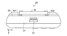
図6は、超音波診断装置20の底面図である。図6において、図1および図4と同じものには同じ符号が付してある。図6に示すように、超音波診断装置20の底部21には、コネクタ51(第1のコネクタ)が設けられている。コネクタ51は、超音波診断装置20がクレードル装置10に装着されたとき、クレードル装置10のコネクタ14と接続される。
FIG. 6 is a bottom view of the ultrasonic
収納された状態の可変スタンド43と、背部25の表面との間には、空間(隙間)が形成される。例えば、図6の点線A21,A22に示すように、収納された状態の可変スタンド43と、背部25の表面との間には、空間が形成される。この空間は、次の図7で説明するように、超音波診断装置20の着脱方向(z軸方向)に沿って伸びている。
A space (gap) is formed between the retracted
図7は、超音波診断装置20の側面図である。図7において、図1、図4、および図6と同じものには同じ符号が付してある。図7の点線A21(図6の点線A21も参照)に示すように、収納された状態の可変スタンド43と、背部25の表面との間の空間は、z軸方向に沿って伸びている。図6の点線A22に示した空間も、図7の点線A21と同様に、z軸方向に沿って伸びている。超音波診断装置20がクレードル装置10に装着されるとき、点線A21,A22に示す空間には、クレードル装置10のガイド13aa,13baが挿し込まれる。
FIG. 7 is a side view of the ultrasonic
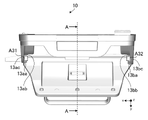
図8は、クレードル装置10の上面図である。図8において、図1と同じものには同じ符号が付してある。
FIG. 8 is a top view of the
図1で説明したように、ガイド13aa,13abは、対向しており、空間を形成している。例えば、図8の点線A31に示すように、ガイド13aa,13abの間には、空間が形成される。同様に、ガイド13ba,13bbは、対向しており、空間を形成している。例えば、図8の点線A32に示すように、ガイド13ba,13bbの間には、空間が形成される。 As explained in FIG. 1, the guides 13aa and 13ab face each other and form a space. For example, a space is formed between the guides 13aa and 13ab as indicated by the dotted line A31 in FIG. Similarly, guides 13ba and 13bb face each other and form a space. For example, as indicated by dotted line A32 in FIG. 8, a space is formed between guides 13ba and 13bb.
図9は、図8のAA矢視断面図である。図9において、図8と同じものには同じ符号が付してある。ガイド13ba,13bbは、超音波診断装置20の着脱方向(z軸方向)に沿って伸びている。従って、ガイド13ba,13bbの間に形成される空間も、点線A32(図8の点線A32も参照)に示すように、z軸方向に沿って伸びている。図8の点線A31に示した空間も、図9の点線A32と同様に、z軸方向に沿って伸びている。
9 is a cross-sectional view taken along line AA of FIG. 8. FIG. In FIG. 9, the same components as in FIG. 8 are denoted by the same reference numerals. The guides 13ba and 13bb extend along the attachment/detachment direction (z-axis direction) of the ultrasonic
超音波診断装置20がクレードル装置10に装着されるとき、図8の点線A31,A32に示す空間に、超音波診断装置20の可変スタンド43の、着脱方向(z軸方向)に沿って伸びている部分が挿入される。例えば、図4の点線A41に示す部分が、図8の点線A31に示す空間に挿入され、図4の点線A42に示す部分が、図8の点線A32に示す空間に挿入される。
When the ultrasonic
また、超音波診断装置20がクレードル装置10に装着されるとき、図8に示すクレードル装置10のガイド13aaは、図6の点線A22に示す空間に挿入され、図8に示すクレードル装置10のガイド13bbは、図6の点線A21に示す空間に挿入される。
When the ultrasonic
すなわち、可変スタンド43の着脱方向に沿って伸びる部分は、ガイド13aa,13abの間と、ガイド13ba,13bbの間とに挿入される。言い換えれば、可変スタンド43の着脱方向に沿って伸びる部分は、レールとしての機能を果たし、着脱方向に伸びるガイド13aa,13abの間と、ガイド13ba,13bbの間とを、着脱方向に沿って摺動する。
That is, the portion of the
なお、ガイド13aa,13ab,13ba,13bbは、クレードル装置10に装着された超音波診断装置20のy軸方向の移動を制限(規制)する。ガイド13ac,13bcは、クレードル装置10に装着された超音波診断装置20のx軸方向の移動を制限する。
The guides 13aa, 13ab, 13ba, and 13bb limit (restrict) movement of the ultrasonic
図10は、クレードル装置10の背面図である。図10において、図1と同じものには同じ符号が付してある。図10に示すように、クレードル装置10の背部60には、電源コネクタ61(第3のコネクタ)と、USBコネクタ62a,62b(第4のコネクタ)と、ネジ穴63と、が設けられている。
10 is a rear view of the
電源コネクタ61には、電源ケーブルのコネクタが接続される。電源コネクタ61は、基部11に設けられているコネクタ14と、配線によって(配線を介して)電気的に接続されている。従って、電源ケーブルを電源コネクタ61に接続すれば、クレードル装置10に装着された超音波診断装置20に電力を供給できる。
A connector of a power cable is connected to the
なお、上記したように、超音波診断装置20をクレードル装置10に装着した場合、超音波診断装置20の電源コネクタ42は、パネル17によって隠され、電源ケーブルが接続されないようになっている。すなわち、超音波診断装置20をクレードル装置10に装着した場合、超音波診断装置20には、クレードル装置10からのみ、外部電源による電力が供給される。つまり、超音波診断装置20には、2つの外部電源による電力が供給されないようになっている。
As described above, when the ultrasonic
USBコネクタ62a,62bには、USBケーブルのコネクタが接続される。USBコネクタ62a,62bは、基部11に設けられているコネクタ14と、配線によって(配線を介して)電気的に接続されている。従って、外部機器と接続されたUSBケーブルをUSBコネクタ62a,62bに接続することにより、クレードル装置10に装着された超音波診断装置20は、外部機器と通信できる。外部機器は、例えば、キーボードやフットスイッチである。
USB cable connectors are connected to the
ネジ穴63は、クレードル装置10を、例えば、カート30や病室の壁や棚に固定するためのネジ穴である。ネジ穴63は、例えば、VASA(Video Electronics Standards Association)規格に基づいて形成されている。
The
以上説明したように、クレードル装置10は、超音波診断装置20の底部21を支持する基部11と、基部11から、超音波診断装置20の着脱方向(z軸方向)に沿って伸び、超音波診断装置20の表示装置23が形成されている前部22とは反対側の背部25を支持する背部支持部12と、を備える。また、クレードル装置10は、超音波診断装置20の背部25に設けられている可変スタンド43(レール)と嵌合し、超音波診断装置20を着脱方向に沿って摺動可能にする、背部支持部12に設けられたガイド13aa,13ab,13ba,13bbを有する。これにより、クレードル装置10は、超音波診断装置20を、容易に着脱可能に支持できる。例えば、超音波診断装置20の可変スタンド43を、クレードル装置10のガイド13aa,13ab,13ba,13bbに合わせ、超音波診断装置20を、クレードル装置10に向って押し込むことにより、超音波診断装置20を、容易にクレードル装置10に装着でき、支持させることができる。また、超音波診断装置20を、クレードル装置10から持ち上げれば、容易にクレードル装置10から取り外すことができる。
As described above, the
また、超音波診断装置20のクレードル装置10への着脱を容易にしたので、超音波診断装置20の使い勝手がよくなる。例えば、超音波診断装置20をクレードル装置10に装着すれば、固定的な使用ができる。また、超音波診断装置20をクレードル装置10から取り外せば、様々な場所での使用ができる。
In addition, since the ultrasonic
また、クレードル装置10は、超音波診断装置20の底部21に設けられたコネクタ51と接続されるコネクタ14を有する。また、クレードル装置10は、基部11のコネクタ14と接続された電源コネクタ61を背部60に有する。これにより、クレードル装置10の電源コネクタ61に電源ケーブルを接続していれば、超音波診断装置20をクレードル装置10に装着するだけで、超音波診断装置20に電源を供給できる。
The
また、クレードル装置10は、基部11のコネクタ14と接続されたUSBコネクタ62a,62bを背部60に有する。これにより、クレードル装置10のUSBコネクタ62a,62bに、外部機器と接続されたUSBケーブルを接続していれば、超音波診断装置20をクレードル装置10に装着するだけで、外部機器と通信できる。すなわち、超音波診断装置20の背部25に設けられているUSBコネクタ44a,44bに、USBケーブルを接続しなくて済む。また、クレードル装置10のUSBコネクタ62a,62bに、外部機器と接続されたUSBケーブルを接続していれば、超音波診断装置20をクレードル装置10から取り外すとき、超音波診断装置20から、USBケーブルを外さなくて済む。
The
また、クレードル装置10は、超音波診断装置20が装着されたとき、超音波診断装置20の背部25に設けられた電源コネクタ42に外部電源が接続されないよう、電源コネクタ42を隠すパネル17を備える。これにより、超音波診断装置20に2つの外部電源が供給されることを防止でき、装置の故障を抑制できる。
The
また、クレードル装置10は、背部支持部12から突出して、超音波診断装置20の背部25に設けられた窪み部41と嵌合する突起部15と、突起部15と連結され、突起部15を背部支持部12内に引っ込めるボタン16とを有する。これにより、クレードル装置10は、超音波診断装置20をしっかりと固定することができる。
The
なお、クレードル装置10の背部60に設けられるコネクタは、USBコネクタに限られない。その他の規格のコネクタであってもよい。また、クレードル装置10の背部60には、超音波探触子のコネクタと接続されるコネクタが備えられてよい。また、このコネクタは、複数備えられてもよい。複数のコネクタを備えた場合には、例えば、クレードル装置に、複数種類の超音波探触子を接続できる。超音波診断装置20の操作者は、複数種類の超音波探触子の中から、所望の超音波探触子を選択し、使用することができる。
The connector provided on the
また、クレードル装置10の基部11に設けられるコネクタ14および背部60に設けられるUSBコネクタ62a,62bの数は、上記の実施形態の数に限定されない。
Also, the number of
また、ガイド13aa,13ab,13ba,13bbには、超音波診断装置20の可変スタンド43が嵌合されるとしたが、これに限られない。例えば、超音波診断装置20の背部25には、ガイド13aa,13ab,13ba,13bbと嵌合し、摺動するレールが、可変スタンド43とは別に設けられてもよい。
Further, although the
また、ガイド13ab,13bbは、可変スタンド43が摺動しやすい材料で構成されてもよい。これにより、超音波診断装置20は、クレードル装置10への着脱の際の摺動が滑らかとなる。ガイド13aa,13baも、可変スタンド43が摺動しやすい材料で構成されてもよい。
Also, the guides 13ab and 13bb may be made of a material that allows the
その他、上記実施の形態は、何れも本発明を実施するにあたっての具体化の一例を示したものに過ぎず、これらによって本発明の技術的範囲が限定的に解釈されてはならないものである。すなわち、本発明はその要旨、またはその主要な特徴から逸脱することなく、様々な形で実施することができる。 In addition, each of the above-described embodiments is merely an example of specific implementation of the present invention, and the technical scope of the present invention should not be construed to be limited by these. Thus, the invention may be embodied in various forms without departing from its spirit or essential characteristics.
10 クレードル装置
11 基部
12 背部支持部
13aa,13ab,13ac,13ba,13bc,13bb ガイド
14,28,51 コネクタ
15 突起部
16 ボタン
17 パネル
20 超音波診断装置
21 底部
22 前部
23 表示装置
24a,24b 側部
25,60 背部
26 上部
27 取っ手
30 カート
31 アーム
41 窪み部
42,61 電源コネクタ
43 可変スタンド
44a,44b,62a,62b USBコネクタ
63 ネジ穴
REFERENCE SIGNS
Claims (11)
前記超音波診断装置の底部を支持する基部と、
前記基部から、前記超音波診断装置の着脱方向に沿って伸び、前記超音波診断装置の表示装置が形成されている前部とは反対側の背部を支持する背部支持部と、
前記超音波診断装置の前記背部に設けられているレールと嵌合し、前記超音波診断装置を前記着脱方向に沿って摺動可能にする、前記背部支持部に設けられたガイドと、
を有し、
前記レールは前記背部を支持する可変スタンドを構成し、前記可変スタンドは前記背部に収納した閉位置と前記背部から起立した開位置とに移動可能であり、
前記ガイドは、第1のガイドと、前記第1のガイドと対向する第2のガイドと、を含み、
前記第1のガイドと前記第2のガイドは、前記可変スタンドを構成する前記レールが前記第1のガイドと前記第2のガイドとで形成される空間に挿入された状態において、前記第1のガイドと前記第2のガイドとが対向する方向に前記超音波診断装置が移動することを制限するように構成されている、
クレードル装置。 A cradle device for detachably supporting an ultrasound diagnostic device,
a base supporting the bottom of the ultrasonic diagnostic apparatus;
a back supporting portion extending from the base along the attachment/detachment direction of the ultrasonic diagnostic apparatus and supporting the back on the side opposite to the front portion of the ultrasonic diagnostic apparatus where the display device is formed;
a guide provided on the back supporting portion that engages with a rail provided on the back of the ultrasonic diagnostic apparatus to allow the ultrasonic diagnostic apparatus to slide along the attachment/detachment direction;
has
The rail constitutes a variable stand that supports the back, and the variable stand is movable between a closed position stored in the back and an open position standing from the back,
The guide includes a first guide and a second guide facing the first guide,
The first guide and the second guide are in a state in which the rail constituting the variable stand is inserted into the space formed by the first guide and the second guide. configured to restrict movement of the ultrasonic diagnostic apparatus in a direction in which the guide and the second guide face each other;
cradle device.
前記超音波診断装置の底部を支持する基部と、
前記基部から、前記超音波診断装置の着脱方向に沿って伸び、前記超音波診断装置の表示装置が形成されている前部とは反対側の背部を支持する背部支持部と、
前記超音波診断装置の前記背部に設けられているレールと嵌合し、前記超音波診断装置を前記着脱方向に沿って摺動可能にする、前記背部支持部に設けられたガイドと、
を有し、
前記背部支持部には、前記超音波診断装置が装着されたとき、前記超音波診断装置の前記背部に設けられた電源コネクタに外部電源が接続されないよう、前記電源コネクタを隠すパネルが設けられている、
クレードル装置。 A cradle device for detachably supporting an ultrasound diagnostic device,
a base supporting the bottom of the ultrasonic diagnostic apparatus;
a back supporting portion extending from the base along the attachment/detachment direction of the ultrasonic diagnostic apparatus and supporting the back on the side opposite to the front portion of the ultrasonic diagnostic apparatus where the display device is formed;
a guide provided on the back supporting portion that engages with a rail provided on the back of the ultrasonic diagnostic apparatus to allow the ultrasonic diagnostic apparatus to slide along the attachment/detachment direction;
has
The back supporting portion is provided with a panel that hides the power connector provided on the back of the ultrasonic diagnostic apparatus so that an external power supply is not connected to the power connector when the ultrasonic diagnostic apparatus is attached. there is
cradle device.
請求項1に記載のクレードル装置。 The back supporting portion is provided with a panel that hides the power connector provided on the back of the ultrasonic diagnostic apparatus so that an external power supply is not connected to the power connector when the ultrasonic diagnostic apparatus is attached. there is
A cradle apparatus according to claim 1.
請求項2に記載のクレードル装置。 The rail is made up of part of a stand provided on the back of the ultrasonic diagnostic apparatus,
3. A cradle device according to claim 2.
請求項1から4のいずれか一項に記載のクレードル装置。 The base is provided with a second connector connected to a first connector provided on the bottom of the ultrasonic diagnostic apparatus,
Cradle device according to any one of claims 1 to 4.
前記第2のコネクタは、前記第3のコネクタと配線によって接続されている、
請求項5に記載のクレードル装置。 The back support portion is provided with a third connector to which an external power supply is connected,
The second connector is connected to the third connector by wiring,
A cradle device according to claim 5.
前記第2のコネクタは、前記第4のコネクタと配線によって接続されている、
請求項5または6に記載のクレードル装置。 A fourth connector to which a signal line is connected is provided on the back support,
The second connector is connected to the fourth connector by wiring,
A cradle device according to claim 5 or 6.
請求項7に記載のクレードル装置。 A foot switch for controlling the operation of the ultrasonic diagnostic apparatus is connected to the fourth connector,
A cradle device according to claim 7.
請求項7または8に記載のクレードル装置。 An ultrasonic probe is connected to the fourth connector,
Cradle device according to claim 7 or 8.
前記突起部は、前記背部支持部に設けられたボタンの押下に連動して、前記背部支持部内に引っ込む、
請求項1から9のいずれか一項に記載のクレードル装置。 The back support portion is provided with a projection that protrudes from the back support and fits into a recess provided in the back of the ultrasonic diagnostic apparatus,
the protrusion retracts into the back support in conjunction with pressing of a button provided on the back support;
Cradle device according to any one of claims 1 to 9.
請求項1から10のいずれか一項に記載のクレードル装置。 the back support is secured to the cart;
Cradle device according to any one of claims 1 to 10.
Priority Applications (3)
| Application Number | Priority Date | Filing Date | Title |
|---|---|---|---|
| JP2017253718A JP7184512B2 (en) | 2017-12-28 | 2017-12-28 | Cradle device |
| US16/195,291 US11406357B2 (en) | 2017-12-28 | 2018-11-19 | Cradle apparatus |
| CN201811589547.4A CN110005908A (en) | 2017-12-28 | 2018-12-25 | Bracket system |
Applications Claiming Priority (1)
| Application Number | Priority Date | Filing Date | Title |
|---|---|---|---|
| JP2017253718A JP7184512B2 (en) | 2017-12-28 | 2017-12-28 | Cradle device |
Publications (2)
| Publication Number | Publication Date |
|---|---|
| JP2019118463A JP2019118463A (en) | 2019-07-22 |
| JP7184512B2 true JP7184512B2 (en) | 2022-12-06 |
Family
ID=67058738
Family Applications (1)
| Application Number | Title | Priority Date | Filing Date |
|---|---|---|---|
| JP2017253718A Active JP7184512B2 (en) | 2017-12-28 | 2017-12-28 | Cradle device |
Country Status (3)
| Country | Link |
|---|---|
| US (1) | US11406357B2 (en) |
| JP (1) | JP7184512B2 (en) |
| CN (1) | CN110005908A (en) |
Families Citing this family (4)
| Publication number | Priority date | Publication date | Assignee | Title |
|---|---|---|---|---|
| JP7184512B2 (en) | 2017-12-28 | 2022-12-06 | コニカミノルタ株式会社 | Cradle device |
| JP7367537B2 (en) * | 2020-01-23 | 2023-10-24 | コニカミノルタ株式会社 | Ultrasound diagnostic equipment |
| JP7661867B2 (en) * | 2021-11-09 | 2025-04-15 | コニカミノルタ株式会社 | Ultrasound diagnostic equipment |
| WO2025023398A1 (en) * | 2023-07-25 | 2025-01-30 | 삼성메디슨 주식회사 | Buffer device and ultrasonic diagnostic device assembly comprising same |
Citations (5)
| Publication number | Priority date | Publication date | Assignee | Title |
|---|---|---|---|---|
| JP2009200799A (en) | 2008-02-21 | 2009-09-03 | Sony Computer Entertainment Inc | Stand and electronic device |
| JP3196455U (en) | 2014-12-12 | 2015-03-12 | 株式会社共栄商事 | Tablet PC floor stand |
| JP2015515312A (en) | 2012-03-26 | 2015-05-28 | テラテク・コーポレーシヨン | Tablet ultrasound system |
| JP6031312B2 (en) | 2012-09-28 | 2016-11-24 | 株式会社日立製作所 | Portable ultrasound imaging device |
| US11406357B2 (en) | 2017-12-28 | 2022-08-09 | Konica Minolta, Inc. | Cradle apparatus |
Family Cites Families (15)
| Publication number | Priority date | Publication date | Assignee | Title |
|---|---|---|---|---|
| JPH11155005A (en) * | 1997-11-20 | 1999-06-08 | Kojima Press Co Ltd | Device for preventing portable telephone set from being left in automobile |
| JP3443300B2 (en) * | 1997-12-08 | 2003-09-02 | 小島プレス工業株式会社 | Connector mechanism |
| JPH11338578A (en) * | 1998-05-29 | 1999-12-10 | Toshiba Corp | Electronic device system and expansion device for expanding functions of electronic device |
| JP3790918B2 (en) * | 1999-04-30 | 2006-06-28 | オリンパス株式会社 | Ultrasonic surgery system |
| US6447451B1 (en) * | 1999-05-04 | 2002-09-10 | Sonosite, Inc. | Mobile ultrasound diagnostic instrument and docking stand |
| GB2360902A (en) | 2000-03-31 | 2001-10-03 | Orange Personal Comm Serv Ltd | Dual position portable support for mobile device |
| CN2872644Y (en) * | 2006-03-21 | 2007-02-21 | 中山华帝燃具股份有限公司 | Safety protecter for power-supply interface |
| CN101271349B (en) | 2007-03-22 | 2010-05-26 | 研华股份有限公司 | medical assistant computer |
| CN101569537B (en) * | 2008-04-29 | 2014-07-09 | Ge医疗系统环球技术有限公司 | Docking station and ultrasonic diagnosis system |
| US8932238B2 (en) * | 2009-09-29 | 2015-01-13 | Liposonix, Inc. | Medical ultrasound device with liquid dispensing device coupled to a therapy head |
| JP5538460B2 (en) * | 2011-04-06 | 2014-07-02 | パナソニック株式会社 | Expansion device and information processing system including the same |
| US10019034B2 (en) * | 2012-03-14 | 2018-07-10 | Popsockets Llc | Docking connector platform for mobile electronic devices |
| WO2014050279A1 (en) * | 2012-09-28 | 2014-04-03 | 日立アロカメディカル株式会社 | Portable ultrasonic imaging device |
| JP6192384B2 (en) | 2013-06-27 | 2017-09-06 | 株式会社日立製作所 | Ultrasonic diagnostic equipment |
| RU2547959C1 (en) * | 2014-06-04 | 2015-04-10 | ООО "Рэй Системс" | Portable medical ultrasonic scanner |
-
2017
- 2017-12-28 JP JP2017253718A patent/JP7184512B2/en active Active
-
2018
- 2018-11-19 US US16/195,291 patent/US11406357B2/en active Active
- 2018-12-25 CN CN201811589547.4A patent/CN110005908A/en active Pending
Patent Citations (5)
| Publication number | Priority date | Publication date | Assignee | Title |
|---|---|---|---|---|
| JP2009200799A (en) | 2008-02-21 | 2009-09-03 | Sony Computer Entertainment Inc | Stand and electronic device |
| JP2015515312A (en) | 2012-03-26 | 2015-05-28 | テラテク・コーポレーシヨン | Tablet ultrasound system |
| JP6031312B2 (en) | 2012-09-28 | 2016-11-24 | 株式会社日立製作所 | Portable ultrasound imaging device |
| JP3196455U (en) | 2014-12-12 | 2015-03-12 | 株式会社共栄商事 | Tablet PC floor stand |
| US11406357B2 (en) | 2017-12-28 | 2022-08-09 | Konica Minolta, Inc. | Cradle apparatus |
Also Published As
| Publication number | Publication date |
|---|---|
| US20190200958A1 (en) | 2019-07-04 |
| JP2019118463A (en) | 2019-07-22 |
| US11406357B2 (en) | 2022-08-09 |
| CN110005908A (en) | 2019-07-12 |
Similar Documents
| Publication | Publication Date | Title |
|---|---|---|
| JP7184512B2 (en) | Cradle device | |
| CN101703408B (en) | Ultrasonograph | |
| RU2734864C2 (en) | Ultrasound visualization system with multimode interface with touch screen | |
| US20150182196A1 (en) | Portable ultrasound imaging apparatus | |
| US8976518B2 (en) | Electronic apparatus | |
| US20120182709A1 (en) | Support arm and image display device | |
| US20150211847A1 (en) | Manual measuring system | |
| WO2013046907A1 (en) | Cart for portable ultrasonic diagnostic device and ultrasonic diagnostic unit | |
| EP2330333A1 (en) | Electronic device stand and image display system | |
| US20090261992A1 (en) | Dual keyboard input device and movable cart having the same mounted thereon | |
| JPH11184395A (en) | Display device | |
| JP2023070380A (en) | Ultrasonic diagnostic apparatus | |
| JP7403604B2 (en) | energizing device | |
| JP2008253602A (en) | Ultrasonic diagnostic apparatus and its holder | |
| WO2016199583A1 (en) | Ultrasonic diagnostic system | |
| TW201226977A (en) | Handwriting device with charger | |
| JP2015104647A (en) | Probe holder and ultrasonic image diagnostic apparatus | |
| JP5872924B2 (en) | Cart for portable ultrasonic diagnostic equipment, portable ultrasonic unit | |
| JP5221890B2 (en) | Ultrasonic diagnostic equipment | |
| JP2021115123A (en) | Ultrasonic diagnostic equipment | |
| JP2828110B2 (en) | Endoscope inspection table | |
| TWI802308B (en) | Electronic device | |
| KR102036894B1 (en) | Display apparatus | |
| JP5749564B2 (en) | Endoscope device | |
| JP2015062446A (en) | Ultrasonic diagnostic device |
Legal Events
| Date | Code | Title | Description |
|---|---|---|---|
| RD02 | Notification of acceptance of power of attorney |
Free format text: JAPANESE INTERMEDIATE CODE: A7422 Effective date: 20190708 |
|
| RD04 | Notification of resignation of power of attorney |
Free format text: JAPANESE INTERMEDIATE CODE: A7424 Effective date: 20191011 |
|
| A621 | Written request for application examination |
Free format text: JAPANESE INTERMEDIATE CODE: A621 Effective date: 20200928 |
|
| A977 | Report on retrieval |
Free format text: JAPANESE INTERMEDIATE CODE: A971007 Effective date: 20210623 |
|
| A131 | Notification of reasons for refusal |
Free format text: JAPANESE INTERMEDIATE CODE: A131 Effective date: 20210713 |
|
| A521 | Request for written amendment filed |
Free format text: JAPANESE INTERMEDIATE CODE: A523 Effective date: 20210910 |
|
| A02 | Decision of refusal |
Free format text: JAPANESE INTERMEDIATE CODE: A02 Effective date: 20211221 |
|
| A521 | Request for written amendment filed |
Free format text: JAPANESE INTERMEDIATE CODE: A523 Effective date: 20220322 |
|
| C60 | Trial request (containing other claim documents, opposition documents) |
Free format text: JAPANESE INTERMEDIATE CODE: C60 Effective date: 20220322 |
|
| A911 | Transfer to examiner for re-examination before appeal (zenchi) |
Free format text: JAPANESE INTERMEDIATE CODE: A911 Effective date: 20220404 |
|
| C21 | Notice of transfer of a case for reconsideration by examiners before appeal proceedings |
Free format text: JAPANESE INTERMEDIATE CODE: C21 Effective date: 20220405 |
|
| A912 | Re-examination (zenchi) completed and case transferred to appeal board |
Free format text: JAPANESE INTERMEDIATE CODE: A912 Effective date: 20220520 |
|
| C211 | Notice of termination of reconsideration by examiners before appeal proceedings |
Free format text: JAPANESE INTERMEDIATE CODE: C211 Effective date: 20220524 |
|
| C22 | Notice of designation (change) of administrative judge |
Free format text: JAPANESE INTERMEDIATE CODE: C22 Effective date: 20220913 |
|
| C23 | Notice of termination of proceedings |
Free format text: JAPANESE INTERMEDIATE CODE: C23 Effective date: 20221025 |
|
| C03 | Trial/appeal decision taken |
Free format text: JAPANESE INTERMEDIATE CODE: C03 Effective date: 20221122 |
|
| C30A | Notification sent |
Free format text: JAPANESE INTERMEDIATE CODE: C3012 Effective date: 20221122 |
|
| A61 | First payment of annual fees (during grant procedure) |
Free format text: JAPANESE INTERMEDIATE CODE: A61 Effective date: 20221124 |
|
| R150 | Certificate of patent or registration of utility model |
Ref document number: 7184512 Country of ref document: JP Free format text: JAPANESE INTERMEDIATE CODE: R150 |