US11406294B2 - System and method for improved monitoring of a sample - Google Patents
System and method for improved monitoring of a sample Download PDFInfo
- Publication number
- US11406294B2 US11406294B2 US16/347,921 US201716347921A US11406294B2 US 11406294 B2 US11406294 B2 US 11406294B2 US 201716347921 A US201716347921 A US 201716347921A US 11406294 B2 US11406294 B2 US 11406294B2
- Authority
- US
- United States
- Prior art keywords
- stimulation
- illumination
- time
- subject
- external field
- Prior art date
- Legal status (The legal status is an assumption and is not a legal conclusion. Google has not performed a legal analysis and makes no representation as to the accuracy of the status listed.)
- Active, expires
Links
Images


Classifications
-
- A—HUMAN NECESSITIES
- A61—MEDICAL OR VETERINARY SCIENCE; HYGIENE
- A61B—DIAGNOSIS; SURGERY; IDENTIFICATION
- A61B5/00—Measuring for diagnostic purposes; Identification of persons
- A61B5/145—Measuring characteristics of blood in vivo, e.g. gas concentration, pH value; Measuring characteristics of body fluids or tissues, e.g. interstitial fluid, cerebral tissue
- A61B5/14532—Measuring characteristics of blood in vivo, e.g. gas concentration, pH value; Measuring characteristics of body fluids or tissues, e.g. interstitial fluid, cerebral tissue for measuring glucose, e.g. by tissue impedance measurement
-
- A—HUMAN NECESSITIES
- A61—MEDICAL OR VETERINARY SCIENCE; HYGIENE
- A61B—DIAGNOSIS; SURGERY; IDENTIFICATION
- A61B5/00—Measuring for diagnostic purposes; Identification of persons
- A61B5/0059—Measuring for diagnostic purposes; Identification of persons using light, e.g. diagnosis by transillumination, diascopy, fluorescence
- A61B5/0062—Arrangements for scanning
- A61B5/0066—Optical coherence imaging
-
- A—HUMAN NECESSITIES
- A61—MEDICAL OR VETERINARY SCIENCE; HYGIENE
- A61B—DIAGNOSIS; SURGERY; IDENTIFICATION
- A61B5/00—Measuring for diagnostic purposes; Identification of persons
- A61B5/0059—Measuring for diagnostic purposes; Identification of persons using light, e.g. diagnosis by transillumination, diascopy, fluorescence
- A61B5/0077—Devices for viewing the surface of the body, e.g. camera, magnifying lens
-
- A—HUMAN NECESSITIES
- A61—MEDICAL OR VETERINARY SCIENCE; HYGIENE
- A61B—DIAGNOSIS; SURGERY; IDENTIFICATION
- A61B5/00—Measuring for diagnostic purposes; Identification of persons
- A61B5/145—Measuring characteristics of blood in vivo, e.g. gas concentration, pH value; Measuring characteristics of body fluids or tissues, e.g. interstitial fluid, cerebral tissue
- A61B5/1455—Measuring characteristics of blood in vivo, e.g. gas concentration, pH value; Measuring characteristics of body fluids or tissues, e.g. interstitial fluid, cerebral tissue using optical sensors, e.g. spectral photometrical oximeters
- A61B5/14558—Measuring characteristics of blood in vivo, e.g. gas concentration, pH value; Measuring characteristics of body fluids or tissues, e.g. interstitial fluid, cerebral tissue using optical sensors, e.g. spectral photometrical oximeters by polarisation
-
- A—HUMAN NECESSITIES
- A61—MEDICAL OR VETERINARY SCIENCE; HYGIENE
- A61B—DIAGNOSIS; SURGERY; IDENTIFICATION
- A61B5/00—Measuring for diagnostic purposes; Identification of persons
- A61B5/145—Measuring characteristics of blood in vivo, e.g. gas concentration, pH value; Measuring characteristics of body fluids or tissues, e.g. interstitial fluid, cerebral tissue
- A61B5/1455—Measuring characteristics of blood in vivo, e.g. gas concentration, pH value; Measuring characteristics of body fluids or tissues, e.g. interstitial fluid, cerebral tissue using optical sensors, e.g. spectral photometrical oximeters
- A61B5/14551—Measuring characteristics of blood in vivo, e.g. gas concentration, pH value; Measuring characteristics of body fluids or tissues, e.g. interstitial fluid, cerebral tissue using optical sensors, e.g. spectral photometrical oximeters for measuring blood gases
Definitions
- the present invention relates to system and method for monitoring of biological parameters and may relate in particular to non-invasive measurement of glucose blood level.
- the human body contains many fluids carrying colloids or other solvents having vital functions within the body.
- blood flowing in the circulatory system delivers necessary substances such as nutrients and oxygen to cells, and transports metabolic waste products away from those cells.
- the blood glucose level (also referred to as blood glucose concentration) may provide indication relating to malfunction of the digestive system, such as diabetes mellitus.
- the blood glucose levels are considered normal within certain range, while higher or lower levels can indicate abnormal condition that might be life threatening and typically requires treatment.
- Patients with diabetes mellitus may be needed to monitor their glucose levels routinely to verify desired glucose range in order to maintain their health.
- Additional blood content parameter may include oxygen levels, alcohol levels etc.
- non-invasive techniques have been devised in the field of measuring blood-related parameters, such as glucose level and oxygen saturation.
- Such techniques include impedance-based as well as optical measurement techniques.
- some glucose measurement techniques are based on near infrared spectroscopy. In such techniques, a tissue is illuminated with light in the infrared spectrum, and the light reflected by the tissue and/or the light transmitted through the tissue is measured. The portion of light that is reflected and/or transmitted is indicative of the blood glucose level.
- Such glucose measurement techniques are used for tissue investigation in different depths varying from 1 to 100 millimeters or 10 to 50 micrometers. Additional glucose measurement techniques use Raman spectroscopy to measure scattered light that has been influenced by the oscillation and rotation caused by glucose.
- Glucose meters based on photo-acoustic spectroscopy are known, configured to measure parameters of an acoustic pressure wave created by rapid heating of the sampled area.
- Other glucose meters operate on measuring changes in the scattering and the polarization parameters of light caused by glucose molecules in the blood.
- Femtosecond pulse interferometry can be used to determine glucose concentration, by measuring the group refraction index of a glucose solution using a time delay of femtosecond order in a time-of-flight method.
- Optical coherence tomography can be used to measure and analyze the interference pattern between the coherently backscattered light from specific layers of tissues and a reference beam.
- Such techniques include:
- U.S. Pat. No. 8,638,991 presents a method for imaging an object.
- the method comprises imaging a coherent speckle pattern propagating from an object, using an imaging system being focused on a plane displaced from the object.
- U.S. Pat. No. 9,668,672 presents a system and method for use in monitoring one or more conditions of a subject's body.
- the system comprises a control unit which comprises an input port for receiving image data and data indicative of at least one external stimulation (external field) applied to a portion of the subject's body during collection of the image data therefrom, a memory utility, and a processor utility.
- the image data is indicative of a sequence of speckle patterns generated by the portion of the subject's body according to a certain sampling time pattern.
- the processor utility is configured and operable for carrying out the following: processing the image data utilizing the data indicative of the applied external field(s), said processing comprising determining a spatial correlation function between successive speckle patterns in the sequence, and determining a time varying spatial correlation function in the form of a time-varying function of at least one feature of the correlation function indicative of a change of the speckle pattern over time; selecting at least one parameter of the time-varying spatial correlation function, and applying to said at least one parameter one or more of the models to determine one or more corresponding body conditions; and generating output data indicative of said one or more corresponding body conditions.
- optical monitoring techniques may provide non-invasive and efficient technique for monitoring parameters of a patient.
- speckle-based detection coherent illumination and detection of variation in secondary speckle patterns generated in light returning, by reflectance and/or scattering, from an inspection region of the patient
- speckle-based detection can be used for measurement of such parameters.
- speckle-based detection The efficiency and accuracy of speckle based monitoring of some parameters such as glucose concentration in blood may be increased utilizing external field stimulation such as magnetic external field.
- external magnetic field causes rotation of light polarization by interaction with glucose molecules due to Faraday Effect, thus allowing monitoring of glucose concentration.
- the technique of the present invention utilizes pulsed illumination that is appropriately timed with operation of an external field stimulation to enable readout of data indicative of one or more desired parameters while reducing effects of undesired field generated vibrations.
- the illumination pulses may be selected to be shorter with respect to rise-time of said undesired stimulation provides for eliminating, or at least significantly reducing a coupling between said desired and undesired stimulations.
- the external field stimulation unit may be configured and operable for generating a time varying magnetic field at vicinity of the inspection region.
- the system may be configured such that said control unit comprises: a memory utility for storing one or more predetermined models indicative of a relation between one or more measurable parameters and one or more conditions of the subject's body; and a processor utility.
- the processor utility may be configured and operable for: processing input data received from the collection unit utilizing data about operation of said external field simulation unit, said processing comprising determining one or more spatial correlation functions between successive speckle patterns in the plurality of data pieces, and determining a time varying spatial correlation function in the form of a time-varying function of at least one feature of the correlation function, the time-varying spatial correlation function being indicative of a change of the speckle pattern over time; selecting at least one parameter of the time-varying spatial correlation function, and applying to said at least one parameter one or more of the models to determine one or more corresponding body conditions; and generating output data indicative of said one or more corresponding body conditions.
- control unit may be operable using one or more processors thereof in accordance with suitable computer readable instructions.
- a method for monitoring one or more parameters of a subjects body comprising: providing a predetermined stimulation at a vicinity of a region to be inspected of said subject's body for a selected stimulation time, providing pulsed coherent illumination onto said region and collecting two or more image data pieces associated with light returning from said region within at least a period of said stimulation time and processing said two or more image data pieces for determining data indicative of said one or more parameters, wherein said pulsed coherent illumination comprises one or more pulses being short with respect to rise-time of mechanical effects of said stimulation to thereby provide time-frequency filtering between effects of said stimulation.
- FIG. 1 schematically illustrates a system for improved monitoring according to some embodiments of the invention
- FIG. 3 exemplifies a technique for increasing of signal to noise ratio according to the technique of the invention.
- the illumination unit 202 is configured for providing pulsed coherent illumination having selected pulse duration and directing the illumination onto an inspection region.
- the inspection region may be a part on a subject's body (e.g. arm, leg, chest etc.).
- the illumination unit 202 typically includes a laser light source and may be configured as CW light source with mechanical shutter or as a pulsed light source such as Q-switch laser unit or any other type of pulsed light source.
- the illumination unit 202 may be configured to provide illumination with specific selected polarization state and orientation.
- the illumination unit may be configured to provide light with linear or elliptical polarization at desired angle with respect to surface of the inspection region, circular polarization or random polarization.
- the collection unit 204 is configured for collecting light returning from the inspection region and operate at a selected sampling rate to generate image data pieces associated with secondary speckle pattern formed by interference of light components in the returning and scattered.
- the collection unit generally includes a detector array (PDA) 111 and a corresponding imaging optics 112 (e.g. one or more lenses) configured for defocused imaging of the inspection region onto the detector 111 .
- the imaging optics 112 is configured for collecting light returning from the inspection region with a selected field of view, and is located at a distance from the PDA 111 such that an image plane formed on the PDA 111 corresponds to an intermediate plane (intermediate object plane) shifted with respect to the inspection region.
- the intermediate plane may be located between the inspection region and the imaging optics or further from the inspection region.
- image data collected by the PDA corresponds to secondary speckle patterns formed by light interference while propagating away from the inspection region.
- the collection unit 204 is configured for generating sequences of image data pieces at a selected frame rate and for transmitting the generated image data pieces to the control unit 100 for processing.
- the collection unit 204 may also include one or more filtering elements such as chromatic filter, polarization filter etc. The use of filtering elements may provide for increased signal to noise ration as well as for separating speckle pattern data in having desire characteristics. Such as different polarization, from the background illumination.
- the control unit 100 When operated according to the pre-stored instructions, the control unit 100 is configured and operable for providing operation commends and operating said measurement unit 110 to provide measured parameters with improved signal to noise ratio (SNR). To this end, the control unit 100 is configured for operating the illumination unit 202 , the collection unit 204 and the external field stimulation unit 502 , e.g. by transmitting data of external field DEF to the external field generator 502 , according to a predetermined operational scheme designed for optimizing data collection. Such predetermined operational scheme may typically include selected timing illumination and image data collection with respect to start and end time of stimulation by the external field generator 502 . Additionally, the control unit 100 is further configured and operable for receiving input data ID indicative of a plurality of data pieces from the collection unit 204 indicative of one or more conditions of the subject's body and for processing the received data and/or store the data and transmit is for further processing.
- SNR signal to noise ratio
- control unit 100 is configured and operable for utilizing a predetermined operational scheme designed according to the present technique for increasing SNR in the collected data ID.
- the control unit 100 is configured for selectively operating the external field generator 502 for providing external stimulation (e.g. AC magnetic field) according to predetermined parameters DEF, such as frequency and amplitude, for a selected time duration herein referred to as stimulation time.
- predetermined parameters DEF such as frequency and amplitude
- control unit 100 further operates the illumination unit 202 and collection unit 204 for illuminating the inspection region and collecting two or more image data pieces associated with speckle patterns in light returning from the inspection region 102 within a predetermined temporal window from the start of the stimulation time.
- control unit 100 operates, by transmitting suitable operation commands, the illumination unit 202 for providing one or more illumination pulses directed at the inspection region. Additionally and simultaneously, the control unit operates the collection unit 204 for collecting two or more image data pieces within the duration of the illumination pulse(s). More specifically, in some configurations, the illumination unit may be configured or operated to generate a single illumination pulse having selected duration shorter than the stimulation time and the collection unit is operated for collecting two or more image data pieces within duration of the illumination pulse.
- the illumination unit is configured and operated to provide one or more (generally two or more) illumination pulses such that the illumination pulses are within a selected portion of the stimulation time
- the collection unit is operated for collecting two or more image data pieces indicative of speckle patterns generated by light returning from the inspection region as a result of the illumination pulses.
- the former configuration is typically more suitable for use with collection unit 204 capable of collecting image data with short exposure time and the latter configuration may be used with collection unit 204 that might be limited with exposure time length such that the illumination pulses provide exposure limits for collection of image data pieces.
- the image data collection scheme of the present technique enables collection of a plurality of two or more image data pieces within a selected temporal period from start point of the external stimulation.
- the selected temporal period for collection of image data pieces, within the stimulation time may be determined in accordance with rise time of mechanical vibrations resulting directly from the stimulation field EF.
- mechanical vibrations may act as undesired noise over desired signals such as variation in speckle patterns of light in selected polarization state, indicating level of Faraday Effect acting on certain molecules, e.g. glucose.
- control unit 100 may generally be configured as a computing unit, or as electronic control unit, and include an operation timing module configured and operable for appropriately timing operation of the stimulation unit 502 , illumination unit 202 and collection unit 204 in accordance with the selected operational scheme.
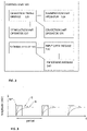
- FIG. 2 schematically illustrating main modules of the control unit 100 .
- the control unit may include an operation timing module 120 (e.g. internal clock and timer module) configured and operable for timing operation of the different units of the system 500 .
- the operation timing module 120 is connected to stimulation unit operator 122 , illumination unit operator 124 and collection unit operator 126 and configured for timing operation of the units by transmitting corresponding signals vie the respective operator modules.
- control unit 100 may include an input data module 130 , processing module 140 and storage utility 135 , for use receiving and processing collected data.
- processing module 140 may be software and/or hardware modules and may be associated with one or more processors of the control unit 100 .
- control unit 100 may include one or more storage utilities and input and output communication ports for network communication as well as for transmitting operational command to the illumination, collection and stimulation units ( 202 , 204 and 502 ). Further, the control unit may also include user interface such as screen and operation buttons for communication with an operator and providing data on operation and determined measurement results.
- the operation timing module 120 is configured to transmit operation signals to the stimulation unit 502 , e.g. via the stimulation unit operator 122 , for providing stimulation for a selected time period. Within the selected time period, the operation timing module 120 operates the illumination unit operator 124 to transmit operation signals to the illumination unit 202 for providing one or more pulses of illumination and operates the collection unit operator 126 to command the collection unit 204 for collecting two or more image data pieces. As indicated above, the illumination unit operator 122 may be configured, according to some embodiments, to cause the illumination unit 202 to provide a single pulse of illumination together with stimulation time, associated with operation of the external field generator 502 , while the collection unit 204 is operated for collecting two or more image data pieces within duration of the illumination pulse.
- the illumination unit operator 122 may be configured to operate the illumination unit 202 to provide a series of two or more pulses starting with operation of the field generator 502 , while the collection unit 204 is operated, by the collection unit operator 124 , for collecting a corresponding series of two or more image data pieces associated with the illumination pulses.
- the use of pulsed illumination of selectively short pulses enables collecting image data associated with short time window (shorter than integration time of the PDA of the collection unit), such that the collection unit may be configured with integration time that is longer than duration of the illumination pulses.
- FIG. 3 shows a graph indicating operation of a sequence of illumination pulses LP, which are operated simultaneously with the external stimulation signal, (e.g. AC magnetic field), expected signals S to be measured and estimated noise N resulting e.g. from mechanical vibrations associated with AC magnetic field.
- the external stimulation signal e.g. AC magnetic field
- expected signals S to be measured e.g. from mechanical vibrations associated with AC magnetic field.
- AC magnetic field may be preferably used.
- the AC magnetic field applied on the glucose molecules causes Faraday rotation to light interacting with the molecules which results in polarization rotation.
- applying AC magnetic field on the sample may also result in small vibrations at a similar frequency as that of the magnetic field.
- vibrations might be sensed together with the vibrations caused by blood flow (for the case of glucose monitoring) or any other desired signals, resulting in addition of noise.
- the inventors of the present invention have found that the mechanical vibrations N caused by the external stimulation (and in particular by AC magnetic field) have rise-time that is longer than that of the Faraday effect (in the case of magnetic field) measured on top of the vibrations associated with blood flow.
- the use of pulsating illumination LP combined with periodic stimulation enables detection of the desired signal S within a short time window where the mechanical vibrations are relatively lower.
- the collected data indicative of speckle patterns is collected by the collection unit, as two or more image data pieces, within the time window of illumination (being a single illumination pulse as exemplified in FIG.
- the technique may include repetitive measurement with a predetermined repetition rate for increasing measurement accuracy, or a single measurement in accordance with desired accuracy and type of the measured signal.
- the technique of the invention provides for monitoring of parameters, such as blood glucose concentration, in presence of external stimulation filed while allowing increased single to noise ratio.
- the present technique utilizes temporal filtering, differentiating between desired signal and noise, using pulsed illumination allowing collection of the desired signal at selected time windows.
Priority Applications (1)
| Application Number | Priority Date | Filing Date | Title |
|---|---|---|---|
| US16/347,921 US11406294B2 (en) | 2016-11-10 | 2017-11-06 | System and method for improved monitoring of a sample |
Applications Claiming Priority (3)
| Application Number | Priority Date | Filing Date | Title |
|---|---|---|---|
| US201662420161P | 2016-11-10 | 2016-11-10 | |
| US16/347,921 US11406294B2 (en) | 2016-11-10 | 2017-11-06 | System and method for improved monitoring of a sample |
| PCT/IL2017/051207 WO2018087751A1 (fr) | 2016-11-10 | 2017-11-06 | Système et procédé destinés à la surveillance améliorée d'un échantillon |
Publications (2)
| Publication Number | Publication Date |
|---|---|
| US20190274602A1 US20190274602A1 (en) | 2019-09-12 |
| US11406294B2 true US11406294B2 (en) | 2022-08-09 |
Family
ID=62109461
Family Applications (1)
| Application Number | Title | Priority Date | Filing Date |
|---|---|---|---|
| US16/347,921 Active 2039-08-16 US11406294B2 (en) | 2016-11-10 | 2017-11-06 | System and method for improved monitoring of a sample |
Country Status (4)
| Country | Link |
|---|---|
| US (1) | US11406294B2 (fr) |
| EP (1) | EP3537956A4 (fr) |
| IL (1) | IL266317A (fr) |
| WO (1) | WO2018087751A1 (fr) |
Families Citing this family (1)
| Publication number | Priority date | Publication date | Assignee | Title |
|---|---|---|---|---|
| JPWO2021215221A1 (fr) * | 2020-04-24 | 2021-10-28 |
Citations (11)
| Publication number | Priority date | Publication date | Assignee | Title |
|---|---|---|---|---|
| US5212667A (en) | 1992-02-03 | 1993-05-18 | General Electric Company | Light imaging in a scattering medium, using ultrasonic probing and speckle image differencing |
| US20010031914A1 (en) * | 1997-06-12 | 2001-10-18 | Tecmed, Incorporated (A New Mexico Corporation) | Method and device for glucose concentration measurement with special attention to blood glucose determinations |
| US20020118903A1 (en) | 2001-02-28 | 2002-08-29 | Cottrell William J. | High amplitude fast optical modulator |
| US20050171415A1 (en) * | 2002-05-08 | 2005-08-04 | Arkray, Inc. | Ingredient concentration measurement method and device |
| US20060025659A1 (en) | 2004-08-02 | 2006-02-02 | Masashi Kiguchi | Optical measuring device for substances in vivo |
| US20120150014A1 (en) | 2007-06-04 | 2012-06-14 | Or-Nim Medical Ltd. | System and method for noninvasively monitoring conditions of a subject |
| US8638991B2 (en) | 2007-07-26 | 2014-01-28 | Bar Ilan University | Motion detection system and method |
| US20140058226A1 (en) * | 2010-12-22 | 2014-02-27 | Boris M. Chernobrod | Method and Apparatus for In Vivo Optical Measurement of Blood Glucose Concentration |
| US20140148658A1 (en) * | 2011-01-28 | 2014-05-29 | Universitat De Valencia | Method and system for non-invasively monitoring biological or biochemical parameters of individual |
| US20160338623A1 (en) * | 2015-05-19 | 2016-11-24 | SAMTD GmbH & Co. KG | Method and apparatus for non-invasive determination of a measured variable of an analyte in a biological body |
| US9668672B2 (en) | 2011-01-28 | 2017-06-06 | Bar Ilan University | Method and system for non-invasively monitoring biological or biochemical parameters of individual |
-
2017
- 2017-11-06 WO PCT/IL2017/051207 patent/WO2018087751A1/fr active Application Filing
- 2017-11-06 EP EP17869508.6A patent/EP3537956A4/fr not_active Withdrawn
- 2017-11-06 US US16/347,921 patent/US11406294B2/en active Active
-
2019
- 2019-04-29 IL IL266317A patent/IL266317A/en unknown
Patent Citations (11)
| Publication number | Priority date | Publication date | Assignee | Title |
|---|---|---|---|---|
| US5212667A (en) | 1992-02-03 | 1993-05-18 | General Electric Company | Light imaging in a scattering medium, using ultrasonic probing and speckle image differencing |
| US20010031914A1 (en) * | 1997-06-12 | 2001-10-18 | Tecmed, Incorporated (A New Mexico Corporation) | Method and device for glucose concentration measurement with special attention to blood glucose determinations |
| US20020118903A1 (en) | 2001-02-28 | 2002-08-29 | Cottrell William J. | High amplitude fast optical modulator |
| US20050171415A1 (en) * | 2002-05-08 | 2005-08-04 | Arkray, Inc. | Ingredient concentration measurement method and device |
| US20060025659A1 (en) | 2004-08-02 | 2006-02-02 | Masashi Kiguchi | Optical measuring device for substances in vivo |
| US20120150014A1 (en) | 2007-06-04 | 2012-06-14 | Or-Nim Medical Ltd. | System and method for noninvasively monitoring conditions of a subject |
| US8638991B2 (en) | 2007-07-26 | 2014-01-28 | Bar Ilan University | Motion detection system and method |
| US20140058226A1 (en) * | 2010-12-22 | 2014-02-27 | Boris M. Chernobrod | Method and Apparatus for In Vivo Optical Measurement of Blood Glucose Concentration |
| US20140148658A1 (en) * | 2011-01-28 | 2014-05-29 | Universitat De Valencia | Method and system for non-invasively monitoring biological or biochemical parameters of individual |
| US9668672B2 (en) | 2011-01-28 | 2017-06-06 | Bar Ilan University | Method and system for non-invasively monitoring biological or biochemical parameters of individual |
| US20160338623A1 (en) * | 2015-05-19 | 2016-11-24 | SAMTD GmbH & Co. KG | Method and apparatus for non-invasive determination of a measured variable of an analyte in a biological body |
Non-Patent Citations (3)
| Title |
|---|
| Ozana, et al, Remote photonic sensing of glucose concentration via analysis of time varied speckle patterns, Advanced Materials Letters, 2018, pp. 624-628, vol. 9(9). |
| Ozana, et al., Improved noncontact optical sensor for detection of glucose concentration and indication of dehydration level, Biomedical Optics Express, May 2014, pp. 1926-1940, vol. 5, No. 6. |
| Ozana, et al., Noncontact speckle-based optical sensor for detection of glucose concentration using magneto-optic effect, Journal of Biomedical Optics, Jun. 2016, pp. 065001-1-065001-6, vol. 21(6). |
Also Published As
| Publication number | Publication date |
|---|---|
| IL266317A (en) | 2019-06-30 |
| EP3537956A1 (fr) | 2019-09-18 |
| EP3537956A4 (fr) | 2020-07-08 |
| US20190274602A1 (en) | 2019-09-12 |
| WO2018087751A1 (fr) | 2018-05-17 |
Similar Documents
| Publication | Publication Date | Title |
|---|---|---|
| RU2648029C2 (ru) | Устройство и способ измерения кровяного давления | |
| US10188325B2 (en) | Wearable, noninvasive glucose sensing methods and systems | |
| EP2207474B1 (fr) | Capteur optique pour déterminer la concentration d'une substance à analyser | |
| US10667795B2 (en) | Wearable, noninvasive glucose sensing methods and systems | |
| US20190083049A1 (en) | Massively Multi-Frequency Ultrasound-Encoded Tomography | |
| US20100087733A1 (en) | Biological information processing apparatus and biological information processing method | |
| JPH07506987A (ja) | 赤外誘導緩和放出による非侵襲的血液化学測定 | |
| JP2012231978A (ja) | 光照射装置およびその制御方法、ならびに被検体情報取得装置 | |
| JP2007510492A (ja) | 人体内の非侵襲的測定の方法およびシステム | |
| KR20080108918A (ko) | 초음파와 광의 상호 작용을 이용하여 피검체의 내부 정보를얻는 의료 기구 | |
| JP2016112277A (ja) | 血圧計測装置、電子機器及び血圧計測方法 | |
| US10595755B2 (en) | System and method for monitoring glucose level | |
| CN101264019A (zh) | 一种基于光声技术的新型便携式无创、连续、实时血糖监测仪 | |
| US20050277817A1 (en) | Noninvasive measurement system for monitoring activity condition of living body | |
| JP5662700B2 (ja) | 生体光計測装置及び生体光計測方法 | |
| WO2019225612A1 (fr) | Dispositif de détection de vaisseau sanguin et son procédé | |
| US11406294B2 (en) | System and method for improved monitoring of a sample | |
| EP3730053A1 (fr) | Dispositif de mesure de lipides et procédé associé | |
| US20160022147A1 (en) | Method and device for monitoring vital functions | |
| US20140275870A1 (en) | Continuous noninvasive measurement of analyte concentration using an optical bridge | |
| US10856739B2 (en) | System and method for monitoring of objects with increased sensitivity | |
| O'Doherty et al. | Dynamic microvascular responses with a high speed TiVi imaging system | |
| JP2021003478A (ja) | 生体センサ | |
| RU2793540C1 (ru) | Портативное устройство и способ для неинвазивного измерения элементов крови | |
| WO2017222033A1 (fr) | Appareil et procédé de traitement d'information |
Legal Events
| Date | Code | Title | Description |
|---|---|---|---|
| AS | Assignment |
Owner name: CONTINUSE BIOMETRICS LTD., ISRAEL Free format text: ASSIGNMENT OF ASSIGNORS INTEREST;ASSIGNORS:ZALEVSKY, ZEEV;GARCIA, JAVIER;OZANA, NISIM NISAN;SIGNING DATES FROM 20171121 TO 20180225;REEL/FRAME:049101/0743 |
|
| FEPP | Fee payment procedure |
Free format text: ENTITY STATUS SET TO UNDISCOUNTED (ORIGINAL EVENT CODE: BIG.); ENTITY STATUS OF PATENT OWNER: SMALL ENTITY |
|
| FEPP | Fee payment procedure |
Free format text: ENTITY STATUS SET TO SMALL (ORIGINAL EVENT CODE: SMAL); ENTITY STATUS OF PATENT OWNER: SMALL ENTITY |
|
| STPP | Information on status: patent application and granting procedure in general |
Free format text: DOCKETED NEW CASE - READY FOR EXAMINATION |
|
| AS | Assignment |
Owner name: BANK LEUMI LE-ISRAEL B.M., ISRAEL Free format text: SECURITY INTEREST;ASSIGNOR:CONTINUSE BIOMETRICS LTD.;REEL/FRAME:058550/0784 Effective date: 20211129 |
|
| STPP | Information on status: patent application and granting procedure in general |
Free format text: NON FINAL ACTION COUNTED, NOT YET MAILED |
|
| STPP | Information on status: patent application and granting procedure in general |
Free format text: NON FINAL ACTION MAILED |
|
| STPP | Information on status: patent application and granting procedure in general |
Free format text: RESPONSE TO NON-FINAL OFFICE ACTION ENTERED AND FORWARDED TO EXAMINER |
|
| STPP | Information on status: patent application and granting procedure in general |
Free format text: NOTICE OF ALLOWANCE MAILED -- APPLICATION RECEIVED IN OFFICE OF PUBLICATIONS |
|
| STPP | Information on status: patent application and granting procedure in general |
Free format text: AWAITING TC RESP., ISSUE FEE NOT PAID |
|
| STPP | Information on status: patent application and granting procedure in general |
Free format text: NOTICE OF ALLOWANCE MAILED -- APPLICATION RECEIVED IN OFFICE OF PUBLICATIONS |
|
| STCF | Information on status: patent grant |
Free format text: PATENTED CASE |