US11402785B2 - Image forming apparatus - Google Patents
Image forming apparatus Download PDFInfo
- Publication number
- US11402785B2 US11402785B2 US16/925,201 US202016925201A US11402785B2 US 11402785 B2 US11402785 B2 US 11402785B2 US 202016925201 A US202016925201 A US 202016925201A US 11402785 B2 US11402785 B2 US 11402785B2
- Authority
- US
- United States
- Prior art keywords
- sheet
- image
- section
- image forming
- instruction
- Prior art date
- Legal status (The legal status is an assumption and is not a legal conclusion. Google has not performed a legal analysis and makes no representation as to the accuracy of the status listed.)
- Active, expires
Links
Images


Classifications
-
- G—PHYSICS
- G03—PHOTOGRAPHY; CINEMATOGRAPHY; ANALOGOUS TECHNIQUES USING WAVES OTHER THAN OPTICAL WAVES; ELECTROGRAPHY; HOLOGRAPHY
- G03G—ELECTROGRAPHY; ELECTROPHOTOGRAPHY; MAGNETOGRAPHY
- G03G15/00—Apparatus for electrographic processes using a charge pattern
- G03G15/50—Machine control of apparatus for electrographic processes using a charge pattern, e.g. regulating differents parts of the machine, multimode copiers, microprocessor control
- G03G15/5016—User-machine interface; Display panels; Control console
-
- G—PHYSICS
- G03—PHOTOGRAPHY; CINEMATOGRAPHY; ANALOGOUS TECHNIQUES USING WAVES OTHER THAN OPTICAL WAVES; ELECTROGRAPHY; HOLOGRAPHY
- G03G—ELECTROGRAPHY; ELECTROPHOTOGRAPHY; MAGNETOGRAPHY
- G03G15/00—Apparatus for electrographic processes using a charge pattern
- G03G15/65—Apparatus which relate to the handling of copy material
- G03G15/6555—Handling of sheet copy material taking place in a specific part of the copy material feeding path
- G03G15/6558—Feeding path after the copy sheet preparation and up to the transfer point, e.g. registering; Deskewing; Correct timing of sheet feeding to the transfer point
-
- G—PHYSICS
- G03—PHOTOGRAPHY; CINEMATOGRAPHY; ANALOGOUS TECHNIQUES USING WAVES OTHER THAN OPTICAL WAVES; ELECTROGRAPHY; HOLOGRAPHY
- G03G—ELECTROGRAPHY; ELECTROPHOTOGRAPHY; MAGNETOGRAPHY
- G03G15/00—Apparatus for electrographic processes using a charge pattern
- G03G15/22—Apparatus for electrographic processes using a charge pattern involving the combination of more than one step according to groups G03G13/02 - G03G13/20
- G03G15/23—Apparatus for electrographic processes using a charge pattern involving the combination of more than one step according to groups G03G13/02 - G03G13/20 specially adapted for copying both sides of an original or for copying on both sides of a recording or image-receiving material
- G03G15/231—Arrangements for copying on both sides of a recording or image-receiving material
- G03G15/232—Arrangements for copying on both sides of a recording or image-receiving material using a single reusable electrographic recording member
- G03G15/234—Arrangements for copying on both sides of a recording or image-receiving material using a single reusable electrographic recording member by inverting and refeeding the image receiving material with an image on one face to the recording member to transfer a second image on its second face, e.g. by using a duplex tray; Details of duplex trays or inverters
-
- G—PHYSICS
- G03—PHOTOGRAPHY; CINEMATOGRAPHY; ANALOGOUS TECHNIQUES USING WAVES OTHER THAN OPTICAL WAVES; ELECTROGRAPHY; HOLOGRAPHY
- G03G—ELECTROGRAPHY; ELECTROPHOTOGRAPHY; MAGNETOGRAPHY
- G03G15/00—Apparatus for electrographic processes using a charge pattern
- G03G15/50—Machine control of apparatus for electrographic processes using a charge pattern, e.g. regulating differents parts of the machine, multimode copiers, microprocessor control
- G03G15/5062—Machine control of apparatus for electrographic processes using a charge pattern, e.g. regulating differents parts of the machine, multimode copiers, microprocessor control by measuring the characteristics of an image on the copy material
-
- G—PHYSICS
- G03—PHOTOGRAPHY; CINEMATOGRAPHY; ANALOGOUS TECHNIQUES USING WAVES OTHER THAN OPTICAL WAVES; ELECTROGRAPHY; HOLOGRAPHY
- G03G—ELECTROGRAPHY; ELECTROPHOTOGRAPHY; MAGNETOGRAPHY
- G03G15/00—Apparatus for electrographic processes using a charge pattern
- G03G15/60—Apparatus which relate to the handling of originals
- G03G15/607—Apparatus which relate to the handling of originals for detecting size, presence or position of original
-
- G—PHYSICS
- G03—PHOTOGRAPHY; CINEMATOGRAPHY; ANALOGOUS TECHNIQUES USING WAVES OTHER THAN OPTICAL WAVES; ELECTROGRAPHY; HOLOGRAPHY
- G03G—ELECTROGRAPHY; ELECTROPHOTOGRAPHY; MAGNETOGRAPHY
- G03G21/00—Arrangements not provided for by groups G03G13/00 - G03G19/00, e.g. cleaning, elimination of residual charge
- G03G21/16—Mechanical means for facilitating the maintenance of the apparatus, e.g. modular arrangements
- G03G21/18—Mechanical means for facilitating the maintenance of the apparatus, e.g. modular arrangements using a processing cartridge, whereby the process cartridge comprises at least two image processing means in a single unit
- G03G21/1803—Arrangements or disposition of the complete process cartridge or parts thereof
- G03G21/1817—Arrangements or disposition of the complete process cartridge or parts thereof having a submodular arrangement
- G03G21/1821—Arrangements or disposition of the complete process cartridge or parts thereof having a submodular arrangement means for connecting the different parts of the process cartridge, e.g. attachment, positioning of parts with each other, pressure/distance regulation
Definitions
- the present disclosure relates to an image forming apparatus.
- a used sheet on only one side of which an image has been formed (may be referred to in the following as a “reused sheet”) is reused so that another image is formed on the other side of the sheet in an image forming apparatus such as a printer or copier.
- the image forming apparatus includes a paper information setting member which sets the reused sheet to be housed in a paper feed cassette.
- An image forming apparatus includes an image forming section, a detector, and a reporting section.
- the image forming section forms an image on a first side of a sheet.
- the sheet has the first side and a second side.
- the detector is positioned upstream of the image forming section in a sheet conveyance direction. The detector detects whether or not an image has been formed on the first side of the sheet.
- the reporting section reports information indicating that an image has been formed on the first side of the sheet when the detector detects that an image has been formed on the first side of the sheet.
- FIG. 1 is a diagram illustrating the image forming apparatus according to a first embodiment of the present disclosure.
- FIG. 2 is a schematic illustration of the image forming apparatus according to the first embodiment of the present disclosure.
- FIG. 3 is a flowchart depicting a first half of a process performed by the image forming apparatus according to the first embodiment of the present disclosure.
- FIG. 4 is a flowchart depicting a second half of the process performed by the image forming apparatus according to the first embodiment of the present disclosure.
- FIG. 5 is a diagram illustrating an image forming apparatus according to a second embodiment of the present disclosure.
- FIG. 6 is a diagram illustrating a threshold table in the second embodiment of the present disclosure.
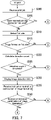
- FIG. 7 is a flowchart depicting a first half of a process performed by the image forming apparatus according to the second embodiment of the present disclosure.
- FIG. 1 is a diagram illustrating the image forming apparatus 100 .
- the image forming apparatus 100 may be communicatively connected to a user terminal (personal computer) through a network.
- the image forming apparatus 100 includes a controller 10 , an image forming section 20 , a detector 30 , a display section 40 , a conveyance section 50 , a reverse conveyance section 60 , a feeder 70 , and storage 80 .
- the storage 80 includes a storage device. Specifically, the storage 80 includes a main storage device such as semiconductor memory and an auxiliary storage device such as one or more of semiconductor memory, a solid-state drive, and a hard disk drive. The storage 80 may include removable media. The storage 80 is an example of a recording medium (non-transitory computer-readable storage medium, for example). The storage 80 stores therein data and computer programs such as software.
- the controller 10 includes a processor.
- the processor includes a central processing unit (CPU), for example.
- the controller 10 controls operation of each element of the image forming apparatus 100 . Specifically, the controller 10 controls the image forming section 20 , the detector 30 , the display section 40 , the conveyance section 50 , the reverse conveyance section 60 , the feeder 70 , and the storage 80 by executing a computer program stored in the storage 80 .
- FIG. 2 is a schematic illustration of the image forming apparatus 100 .
- An electrographic image forming apparatus 100 is described as an example in the present specification, but the present disclosure may also be applied to an inkjet image forming apparatus 100 .
- the image forming apparatus 100 is a color multifunction peripheral, for example.
- the image forming apparatus 100 includes an ejection section 90 , a first conveyance path L 1 , and a second conveyance path L 2 .
- the feeder 70 includes a cassette 71 and a feed roller 72 .
- the cassette 71 houses a sheet P.
- the feed roller 72 feeds the sheet P to the first conveyance path L 1 .
- Examples of the sheet P include plain paper, copy paper, recycled paper, thin paper, thick paper, glossy paper, and an overhead projector (OHP) sheet.
- OHP overhead projector
- one side and another side of the sheet P an image has not been formed on at least the one side but an image may or may not be formed on the other side in the present embodiment. That is, in the present embodiment, the sheet P is a blank sheet or a reused sheet, for example.
- the first conveyance path L 1 is equivalent to an example of a “conveyance path”.
- the sheet P has a first side P 1 and a second side P 2 .
- the upper side of the sheet P housed in the cassette 71 is the first side P 1 and the lower side is the second side P 2 .
- a user places the sheet P in the cassette 71 such that a side of the sheet P on which an image has not been formed faces upward. Accordingly, when the user places the sheet P in a correct orientation in the cassette 71 , an image has not been formed on the first side P 1 of the sheet P. When the user places the sheet P in an incorrect orientation in the cassette 71 , an image has been formed on the first side P 1 of the sheet P.
- the image forming section 20 forms an image on the sheet P.
- the image forming section 20 includes a transfer section 21 , a plurality of photosensitive drums 22 , a plurality of chargers 23 , a plurality of exposure sections 24 , a plurality of developing sections 25 , an intermediate transfer belt 26 , and a fixing section 27 .
- Each photosensitive drum 22 is drum-shaped and has an axis of rotation.
- the photosensitive drum 22 rotates clockwise around the axis of rotation thereof.
- the photosensitive drum 22 has a photosensitive layer on the outer circumferential surface thereof.
- a cyan toner image is formed on one of the photosensitive drums 22 .
- a magenta toner image is formed on another one of the photosensitive drums 22 .
- a yellow toner image is formed on still another one of the photosensitive drums 22 .
- a black toner image is formed on yet another one of the photosensitive drums 22 .
- Each charger 23 charges the photosensitive layer of a corresponding photosensitive drum 22 to a prescribed potential.
- Each exposure section 24 radiates laser light to expose the photosensitive layer of a corresponding photosensitive drum 22 .
- the exposure section 24 exposes the photosensitive drum 22 based on image data. As a result, an electrostatic latent image is formed on the photosensitive drum 22 .
- Each developing section 25 develops the electrostatic latent image formed on a corresponding photosensitive drum 22 .
- the developing section 25 includes a development roller.
- the development roller supplies toner to the photosensitive drum 22 and develops the electrostatic latent image formed on the photosensitive drum 22 to form a toner image. As a result, a toner image is formed on the outer circumferential surface of the photosensitive drum 22 .
- the intermediate transfer belt 26 is an endless belt. A toner image with a plurality of colors is formed on the intermediate transfer belt 26 . Specifically, the toner images formed on the photosensitive drums 22 are transferred to the intermediate transfer belt 26 .
- the transfer section 21 includes a transfer roller 21 a .
- the transfer roller 21 a transfers to the sheet P the image previously transferred to the intermediate transfer belt 26 .
- an image is formed on the sheet P.
- the first side P 1 of the sheet P conveyed from the feeder 70 faces the intermediate transfer belt 26
- the second side P 2 faces the transfer roller 21 a .
- the toner image is transferred to the first side P 1 of the sheet P. That is, the image forming section 20 forms an image on the first side P 1 of the sheet P.
- the fixing section 27 applies heat and pressure to the sheet P to fix the image formed on the sheet P to the sheet P. Having passed through the fixing section 27 , the sheet P is conveyed to the ejection section 90 by the conveyance section 50 .
- the display section 40 has a touch panel 41 and an operation button 42 .
- the touch panel 41 has a display device 43 and a touch sensor 45 .
- the display device 43 displays either or both of various screens and images, for example.
- the display device 43 is a liquid-crystal display (LCD), for example.
- the touch sensor 45 receives operation from the user.
- the touch sensor 45 is located over the display surface of the display device 43 , for example.
- the operation button 42 receives operation from the user.
- the display section 40 is equivalent to an example of a “reporting section”.
- the display section 40 displaying either or both of a screen and an image as information is equivalent to an example of a “reporting section reporting information”.
- the touch panel 41 generates operation information indicating content of operation from the user each time the operation from the user is received. For example, a plurality of icons is displayed on the touch panel 41 . The user taps an icon. The touch panel 41 generates information indicating that the icon has been tapped as the operation information.
- the display section 40 changes the image displayed on the touch panel 41 according to the operation from the user. Specifically, the display section 40 displays on the touch panel 41 an image corresponding to the icon operated by the user among the plurality of icons displayed on the touch panel 41 . The display section 40 reads out information corresponding to the image displayed on the touch panel 41 from the storage 80 .
- the first conveyance path L 1 extends from the feeder 70 to the ejection section 90 .
- the first conveyance path L 1 guides the sheet P from the feeder 70 to the ejection section 90 .
- the conveyance section 50 conveys the sheet P along the first conveyance path L 1 in a sheet conveyance direction D. In a case where the first side P 1 and the second side P 2 of the sheet P are reversed, the conveyance section 50 conveys the sheet P having passed through the fixing section 27 to the reverse conveyance section 60 .
- the detector 30 is positioned upstream of the image forming section 20 in the sheet conveyance direction D. In the present embodiment, the detector 30 is positioned above the cassette 71 .
- Examples of the detector 30 include a complementary metal-oxide-semiconductor (CMOS) image sensor and a charge-coupled device (CCD) sensor.
- CMOS complementary metal-oxide-semiconductor
- CCD charge-coupled device
- the detector 30 is preferably a contact image sensor (CIS) unit, for example.
- the detector 30 detects whether or not an image has been formed on the first side P 1 of the sheet P. Specifically, the detector 30 detects whether or not an image has been formed on the first side P 1 of the sheet P housed in the cassette 71 .
- the manufacturing cost of the image forming apparatus 100 can be reduced more in a case where the detector 30 is a CMOS image sensor or a CCD sensor than in a case where the detector 30 is a CIS unit. In a case where the detector 30 is a CIS unit, the entire first side P 1 of the sheet P can be detected. As a result, whether or not an image has been formed on the first side P 1 of the sheet P can be more accurately detected.
- the detector 30 detecting that an image has been formed on the first side P 1 of the sheet P is equivalent to a side with an image formed thereon of the sheet P facing the intermediate transfer belt 26 in the transfer section 21 . Accordingly, in a case where the detector 30 detects that an image has been formed on the first side P 1 of the sheet P, the image forming section 20 forms an image on the side with an image formed thereon of the sheet P if image formation on the sheet P is continued without reversing the sheet P.
- the ejection section 90 ejects the sheet P out of the image forming apparatus 100 . Specifically, the ejection section 90 ejects the sheet P having passed through the fixing section 27 out of the image forming apparatus 100 .
- the receiver 11 for example receives a print job from the user terminal through the network.
- the print job includes for example image data and an instruction to form an image on the sheet P based on the image data.
- the print job may also include for example an instruction for the image forming section 20 to further form an image over an image already formed on the first side P 1 of the sheet P (may be referred to in the following as a “superimposed printing instruction”).
- the print job may include an instruction for the image forming section 20 to form a character image over an entry column image already formed on the sheet P.
- the operation controller 12 controls operation of the image forming section 20 based on the print job. That is, the image forming section 20 operates based on the print job.
- the operation controller 12 also controls operation of the conveyance section 50 and the reverse conveyance section 60 , for example.
- the display controller 13 for example controls the display section 40 so as to display either or both of various screens and images.
- the display controller 13 causes the display section 40 to display information indicating that an image has been formed on the first side P 1 of the sheet P. Accordingly, the user can know that the one side and the other side of the sheet P housed in the image forming apparatus 100 (cassette 71 ) are inverted by viewing the information displayed on the display section 40 . As a result, the user can be alerted that the sheet P is placed in an incorrect orientation in the image forming apparatus 100 .
- the display controller 13 causes the display section 40 to display information for receiving an instruction from the user as to whether or not to continue image formation on the sheet P.
- the user enters an instruction through the display section 40 as to whether or not to continue image formation on the sheet P.
- the receiving section 14 for example receives an instruction from the user through the display section 40 . Specifically, in a case where the user inputs through the display section 40 an instruction to continue image formation on the sheet P, the receiving section 14 receives through the display section 40 the instruction to continue image formation on the sheet P. In a case where the user inputs through the display section 40 an instruction not to continue image formation on the sheet P, the receiving section 14 receives through the display section 40 an instruction to stop image formation on the sheet P.
- the operation controller 12 controls the operation of the image forming section 20 based on the instruction received by the receiving section 14 as to whether or not to continue image formation on the sheet P. For example, the operation controller 12 controls the operation of the image forming section 20 so as to continue image formation on the sheet P when the receiving section 14 receives the instruction to continue image formation on the sheet P. By contrast, the operation controller 12 controls the operation of the image forming section 20 so as to stop image formation on the sheet P when the receiving section 14 receives the instruction not to continue image formation on the sheet P.
- the sheet P on which image formation has been stopped is ejected out of the image forming apparatus 100 by the ejection section 90 without an image being formed thereon. Accordingly, the user can select whether or not to continue image formation on the sheet P according to the purpose of the sheet P even in a case where the sheet P is conveyed with the one side and the other side thereof reversed. As a result, convenience is improved for the user.
- the display controller 13 In response to the receiving section 14 receiving the instruction to continue image formation on the sheet P, the display controller 13 causes the display section 40 to display for example information related to reversal of the sheet P. Specifically, the display controller 13 causes the display section 40 to display information for receiving an instruction from the user as to whether or not to reverse the first side P 1 and the second side P 2 of the sheet P. The user enters the instruction as to whether or not to continue image formation on the sheet P through the display section 40 . The receiving section 14 then receives the instruction from the user through the display section 40 as to whether or not to reverse the first side P 1 and the second side P 2 of the sheet P.
- the receiving section 14 receives the instruction from the user through the display section 40 as to whether or not to reverse the first side P 1 and the second side P 2 of the sheet P when the detector 30 detects that an image has been formed on the first side P 1 of the sheet P.
- the operation controller 12 controls the operation of the reverse conveyance section 60 .
- the operation controller 12 controls the operation of the reverse conveyance section 60 so as to reverse the first side P 1 and the second side P 2 of the sheet P when the receiving section 14 receives an instruction to reverse the first side P 1 and the second side P 2 of the sheet P.
- the first side P 1 and the second side P 2 of the sheet P can be reversed inside the image forming apparatus 100 without the user manually reversing the first side P 1 and the second side P 2 of the sheet P even in a case where the sheet P has been placed in an incorrect orientation in the cassette 71 .
- a burden on the user to manually reverse the first side P 1 and the second side P 2 of the sheet P can be eliminated and convenience is improved for the user.
- the operation controller 12 controls the operation of the image forming section 20 to form an image on the first side P 1 of the sheet P without reversing the first side P 1 and the second side P 2 of the sheet P. Accordingly, image formation on the sheet P can continue according to the purpose of the sheet P without reversing the first side P 1 and the second side P 2 of the sheet P even in a case where the sheet P is conveyed with a side thereof that has an image formed thereon facing the intermediate transfer belt 26 . As a result, unnecessary reversal of the first side P 1 and the second side P 2 of the sheet P can be prevented and convenience is improved for the user.
- the image forming section 20 forms an image on the first side P 1 of the sheet P independent of a result of detection by the detector 30 . Accordingly, image formation on the sheet P can continue according to the instruction included in the print job without receiving an instruction related to continuation of image formation from the user even in a case where an image has been formed on the first side P 1 of the sheet P. As a result, a burden on the user to enter an instruction related to the continuation of image formation through the display section 40 can be eliminated and convenience is improved for the user.
- the display controller 13 does not cause the display section 40 to display information indicating that an image has been formed on the first side P 1 of the sheet P. Accordingly, the display section 40 can be prevented from unnecessarily displaying information indicating that an image has been formed on the first side P 1 of the sheet P.
- FIG. 3 is a flowchart depicting a first half of a process performed by the image forming apparatus 100 .
- FIG. 4 is a flowchart depicting a second half of the process performed by the image forming apparatus 100 .
- Step S 100 the receiver 11 receives a print job from the user terminal.
- Step S 105 the detector 30 detects whether or not an image has been formed on the first side P 1 of the sheet P.
- Step S 110 the controller 10 determines whether or not an image has been formed on the first side P 1 of the sheet P based on the result of detection by the detector 30 in Step S 105 .
- Step S 110 the process advances to Step S 115 .
- Step S 115 the display controller 13 controls the display section 40 so as to display information indicating that an image has been formed on the first side P 1 of the sheet P as image detection information. As a result, the display section 40 displays the information indicating that an image has been formed on the first side P 1 of the sheet P. Additionally, the display controller 13 causes the display section 40 to display information for receiving an instruction from the user as to whether or not to continue image formation on the sheet P. As a result, the display section 40 displays the information for receiving an instruction from the user as to whether or not to continue image formation on the sheet P.
- Step S 120 the receiving section 14 receives an instruction from the user through the display section 40 as to whether or not to continue image formation on the sheet P.
- Step S 125 the receiving section 14 determines whether or not the instruction received in Step S 120 indicates continuation of image formation on the sheet P.
- an affirmative determination Yes is made in Step S 125 , that is, the receiving section 14 receives an instruction to continue image formation on the sheet P, the process advances to Step S 130 .
- Step S 130 the display controller 13 causes the display section 40 to display information related to reversal of the sheet P. Specifically, the display controller 13 causes the display section 40 to display information for receiving an instruction from the user as to whether or not to reverse the first side P 1 and the second side P 2 of the sheet P. As a result, the display section 40 displays a screen for receiving an instruction from the user as to whether or not to reverse the first side P 1 and the second side P 2 of the sheet P.
- Step S 135 the receiving section 14 receives an instruction related to the reversal of the sheet P through the display section 40 . That is, the receiving section 14 receives an instruction from the user through the display section 40 as to whether or not to reverse the first side P 1 and the second side P 2 of the sheet P.
- Step S 140 the receiving section 14 determines whether or not the instruction received in Step S 135 is an instruction to reverse the first side P 1 and the second side P 2 of the sheet P.
- an affirmative determination that is, when the instruction received by the receiving section 14 is an instruction to reverse the first side P 1 and the second side P 2 of the sheet P, the process advances to Step S 145 .
- Step S 145 the operation controller 12 controls the operation of the reverse conveyance section 60 so as to reverse the first side P 1 and the second side P 2 of the sheet P.
- the reverse conveyance section 60 reverses the first side P 1 and the second side P 2 of the sheet P.
- Step S 150 the operation controller 12 controls the image forming section 20 so as to form an image on the sheet P.
- the image forming section 20 forms an image on the sheet P.
- Step S 155 the operation controller 12 controls the conveyance section 50 and the ejection section 90 so as to eject the sheet P out of the image forming apparatus 100 .
- the conveyance section 50 and the ejection section 90 eject the sheet P out of the image forming apparatus 100 .
- Step S 110 when a negative determination (No) is made in Step S 110 , that is, an image has not been formed on the first side P 1 of the sheet P, the process advances to Step S 150 .
- An image not having been formed on the first side P 1 of the sheet P is equivalent to an image not having been formed on the first side P 1 of the sheet P to which a toner image is to be transferred. Accordingly, when an image has not been formed on the first side P 1 of the sheet P, the image forming section 20 forms an image on the first side P 1 of the sheet P without the receiving section 14 receiving an instruction related to continuation of image formation from the user in Step S 150 .
- Step S 125 when a negative determination (No) is made in Step S 125 , that is, the receiving section 14 receives an instruction not to continue image formation on the sheet P, the process advances to Step S 155 .
- the sheet P is ejected out of the image forming apparatus 100 without the image forming section 20 forming an image on the first side P 1 or the second side P 2 of the sheet P.
- Step S 140 when a negative determination (No) is made in Step S 140 , that is, when the instruction received by the receiving section 14 is an instruction not to reverse the sheet P, the process advances to Step S 150 .
- Step S 150 the image forming section 20 forms an image on the first side P 1 of the sheet P with an image already formed thereon.
- the image forming apparatus 100 a of the second embodiment differs from the image forming apparatus 100 of the first embodiment in that the controller 10 includes a calculating section 15 and a determining section 16 .
- the controller 10 includes a calculating section 15 and a determining section 16 .
- FIG. 5 is a diagram illustrating the image forming apparatus 100 a of the second embodiment.
- the processor of the controller 10 functions as the receiver 11 , the operation controller 12 , the display controller 13 , the receiving section 14 , the calculating section 15 , and the determining section 16 by executing a computer program stored in the storage device of the storage 80 . That is, the controller 10 includes the receiver 11 , the operation controller 12 , the display controller 13 , the receiving section 14 , the calculating section 15 , and the determining section 16 .
- the receiver 11 , the operation controller 12 , the display controller 13 , and the receiving section 14 are the same as in the first embodiment, and description thereof is accordingly omitted.
- the calculating section 15 calculates an image detection count through detection by the detector 30 each time the detector 30 detects that an image has been formed on the first side P 1 of the sheet P.
- the determining section 16 determines whether or not the image detection count through detection by the detector 30 is equal to or greater than a threshold. Accordingly, either or both of the operation controller 12 and the display controller 13 can control at least one element included in the image forming apparatus 100 a according to a result of determination by the determining section 16 .
- the display controller 13 can cause the display section 40 to display information indicating that the sheet P is placed in an incorrect orientation in the cassette 71 only when the determining section 16 determines that the detection count is equal to or greater than the threshold. As a result, trouble for the user of constantly identifying that the sheet P is placed in an incorrect orientation in the cassette 71 can be reduced.
- the display controller 13 for example causes the display section 40 to display information for receiving an instruction from the user as to whether or not to continue image formation on the sheet P.
- the user enters through the display section 40 an instruction as to whether or not to continue image formation on the sheet P.
- the receiving section 14 then receives an instruction from the user through the display section 40 as to whether or not to continue image formation on the sheet P. That is, when the determining section 16 determines that the image detection count is equal to or greater than the threshold, the receiving section 14 receives an instruction from the user through the display section 40 as to whether or not to continue image formation on the sheet P.
- the operation controller 12 controls the operation of the image forming section 20 based on the instruction received by the receiving section 14 as to whether or not to continue image formation on the sheet P.
- the display section 40 does not display information for receiving an instruction as to whether or not to continue image formation on the sheet P until the image detection count through detection by the detector 30 reaches the threshold even in a case where the sheet P is placed in an incorrect orientation in the cassette 71 .
- trouble for the user caused by constantly entering an instruction as to whether or not to continue image formation on the sheet P can be reduced.
- FIG. 6 is a diagram illustrating a threshold table Tb.
- the threshold table Tb stores user names C 1 , user IDs C 2 , thresholds C 3 , and detection counts C 4 in association with each other.
- Each user name C 1 exhibits a name of a user.
- Each user ID C 2 exhibits identification information identifying a user. In the present embodiment, the user ID C 2 exhibits an ID which identifies the user.
- Each threshold C 3 exhibits a threshold set per user.
- Each detection count C 4 exhibits an image detection count calculated per user.
- the threshold is set per user.
- the calculating section 15 calculates an image detection count through detection by the detector 30 per user.
- the determining section 16 determines whether or not the image detection count is equal to or greater than the threshold per user.
- the threshold can be arbitrarily set by a user. Accordingly, the occasion at which the display section 40 displays information indicating that the sheet P is placed in an incorrect orientation in the cassette 71 can be adjusted according to the usage of the image forming apparatus 100 a per user.
- the user ID C 2 of a user 1 is “NN1”, the threshold C 3 is “5”, and the detection count C 4 is “0”. Accordingly, when the detector 30 has successively detected an image five times in operation of the image forming apparatus 100 a based on a print job received from the user 1, the display section 40 displays information for receiving an instruction as to whether or not to continue image formation on the sheet P.
- the threshold C 3 of a user 2 is “10” and the detection count C 4 is “1”. Accordingly, when the detector 30 has successively detected an image nine times in operation of the image forming apparatus 100 a based on a print job received from the user 2, the display section 40 displays information for receiving an instruction as to whether or not to continue image formation on the sheet P.
- FIG. 7 is a flowchart depicting a first half of the process performed by the image forming apparatus 100 a according to the second embodiment.
- FIG. 8 is a flowchart depicting a second half of the process performed by the image forming apparatus 100 a according to the second embodiment.
- Step S 200 in FIG. 7 has the same processing content as Step S 100 in FIG. 3
- Steps S 210 and S 215 in FIG. 7 respectively have the same processing content as Steps S 105 and S 110 in FIG. 3
- Steps S 230 to S 270 in FIGS. 7 and 8 respectively have the same processing content as Steps S 115 to S 155 in FIGS. 3 and 4 .
- description thereof is omitted.
- the image forming section 20 continues image formation on the first side P 1 of the sheet P without the display controller 13 causing the display section 40 to display information indicating that an image has been formed on the first side P 1 of the sheet P even in a case where the sheet P is placed in an incorrect orientation in the cassette 71 .
- the reporting section is the display section 40 .
- the reporting section need only report information to the user, and may be an audio output section.
- the audio output section reports information to the user using an alarm sound or the like.
- the sheet P for which image formation has been stopped is conveyed by the feed roller 72 and ejected out of the image forming apparatus 100 without an image being formed thereon.
- the feed roller 72 need not convey the sheet P in response to detection of an image having been formed on the first side P 1 of the sheet P. That is, the feed roller 72 may stop feeding of the sheet P to the first conveyance path L 1 in response to the detector 30 detecting that an image has been formed on the first side P 1 of the sheet P.
- the feed roller 72 may stop feeding of the sheet P for which image formation has been stopped to the first conveyance path L 1 .
- the user manually reverses the sheet P placed in an incorrect orientation in the cassette 71 . Accordingly, a situation in which the conveyance section 50 unnecessarily conveys the sheet P can be prevented. As a result, degradation of the conveyance section 50 due to the conveyance of the sheet P can be prevented, for example.
Abstract
Description
Claims (7)
Applications Claiming Priority (3)
| Application Number | Priority Date | Filing Date | Title |
|---|---|---|---|
| JP2019-133664 | 2019-07-19 | ||
| JPJP2019-133664 | 2019-07-19 | ||
| JP2019133664A JP2021018319A (en) | 2019-07-19 | 2019-07-19 | Image forming apparatus |
Publications (2)
| Publication Number | Publication Date |
|---|---|
| US20210018870A1 US20210018870A1 (en) | 2021-01-21 |
| US11402785B2 true US11402785B2 (en) | 2022-08-02 |
Family
ID=74343699
Family Applications (1)
| Application Number | Title | Priority Date | Filing Date |
|---|---|---|---|
| US16/925,201 Active 2040-08-19 US11402785B2 (en) | 2019-07-19 | 2020-07-09 | Image forming apparatus |
Country Status (2)
| Country | Link |
|---|---|
| US (1) | US11402785B2 (en) |
| JP (1) | JP2021018319A (en) |
Citations (7)
| Publication number | Priority date | Publication date | Assignee | Title |
|---|---|---|---|---|
| JP2004117428A (en) | 2002-09-24 | 2004-04-15 | Ricoh Co Ltd | Image forming apparatus |
| US20160378034A1 (en) * | 2013-11-29 | 2016-12-29 | Canon Kabushiki Kaisha | Image forming apparatus and image forming system |
| US20170149996A1 (en) * | 2015-11-23 | 2017-05-25 | Kabushiki Kaisha Toshiba | Image reading apparatus and image reading method |
| US20170149992A1 (en) * | 2015-11-24 | 2017-05-25 | Kabushiki Kaisha Toshiba | Image forming apparatus and method of controlling a display for selecting a sheet feeding cassette source |
| US20180039213A1 (en) * | 2015-02-20 | 2018-02-08 | Canon Kabushiki Kaisha | Apparatus and system for forming image |
| US20180089545A1 (en) * | 2016-09-28 | 2018-03-29 | Konica Minolta, Inc. | Image forming device, image forming system, and warning display method |
| US20180257418A1 (en) * | 2017-03-10 | 2018-09-13 | Kabushiki Kaisha Toshiba | Printing amount management apparatus and method |
-
2019
- 2019-07-19 JP JP2019133664A patent/JP2021018319A/en active Pending
-
2020
- 2020-07-09 US US16/925,201 patent/US11402785B2/en active Active
Patent Citations (7)
| Publication number | Priority date | Publication date | Assignee | Title |
|---|---|---|---|---|
| JP2004117428A (en) | 2002-09-24 | 2004-04-15 | Ricoh Co Ltd | Image forming apparatus |
| US20160378034A1 (en) * | 2013-11-29 | 2016-12-29 | Canon Kabushiki Kaisha | Image forming apparatus and image forming system |
| US20180039213A1 (en) * | 2015-02-20 | 2018-02-08 | Canon Kabushiki Kaisha | Apparatus and system for forming image |
| US20170149996A1 (en) * | 2015-11-23 | 2017-05-25 | Kabushiki Kaisha Toshiba | Image reading apparatus and image reading method |
| US20170149992A1 (en) * | 2015-11-24 | 2017-05-25 | Kabushiki Kaisha Toshiba | Image forming apparatus and method of controlling a display for selecting a sheet feeding cassette source |
| US20180089545A1 (en) * | 2016-09-28 | 2018-03-29 | Konica Minolta, Inc. | Image forming device, image forming system, and warning display method |
| US20180257418A1 (en) * | 2017-03-10 | 2018-09-13 | Kabushiki Kaisha Toshiba | Printing amount management apparatus and method |
Also Published As
| Publication number | Publication date |
|---|---|
| US20210018870A1 (en) | 2021-01-21 |
| JP2021018319A (en) | 2021-02-15 |
Similar Documents
| Publication | Publication Date | Title |
|---|---|---|
| US20120287455A1 (en) | Checking system, control method of checking system, and storage medium | |
| JP2023038272A (en) | Image formation device, medium discrimination method, and program | |
| JP4152235B2 (en) | Image processing system | |
| JP6469456B2 (en) | Image forming apparatus, image forming method, and image forming program | |
| US10754282B2 (en) | Image forming apparatus | |
| US11402785B2 (en) | Image forming apparatus | |
| JP5764187B2 (en) | Image forming apparatus | |
| JP6225589B2 (en) | Image forming apparatus | |
| US20040037600A1 (en) | Image forming apparatus | |
| US9001341B2 (en) | Printing apparatus, control method for printing apparatus, and storage medium | |
| US9594530B2 (en) | Image forming apparatus | |
| JP5433619B2 (en) | Image forming apparatus | |
| JP2013104948A (en) | Image forming apparatus, method, system, and printer driver | |
| US20200267269A1 (en) | Multifunctional apparatus | |
| US10939008B2 (en) | Image forming apparatus | |
| JP7235065B2 (en) | image forming device | |
| US11623833B2 (en) | Conveyance device and image forming apparatus | |
| US20230280147A1 (en) | Sheet property measurement device and image forming apparatus | |
| US20240085837A1 (en) | Image forming apparatus the controls operation depending on whether show-through of sheet is detected | |
| US20220129713A1 (en) | Image forming apparatus and image processing apparatus | |
| JP2017134273A (en) | Image forming apparatus | |
| JP2023163652A (en) | Image forming device | |
| JP4882874B2 (en) | Image forming apparatus | |
| JP2012250463A (en) | Printing apparatus, and method for controlling printing apparatus, and program | |
| JP2021054617A (en) | Image forming device |
Legal Events
| Date | Code | Title | Description |
|---|---|---|---|
| AS | Assignment |
Owner name: KYOCERA DOCUMENT SOLUTIONS INC., JAPAN Free format text: ASSIGNMENT OF ASSIGNORS INTEREST;ASSIGNOR:TSUTSUMI, YOSHIAKI;REEL/FRAME:053168/0862 Effective date: 20200624 |
|
| FEPP | Fee payment procedure |
Free format text: ENTITY STATUS SET TO UNDISCOUNTED (ORIGINAL EVENT CODE: BIG.); ENTITY STATUS OF PATENT OWNER: LARGE ENTITY |
|
| STPP | Information on status: patent application and granting procedure in general |
Free format text: DOCKETED NEW CASE - READY FOR EXAMINATION |
|
| STPP | Information on status: patent application and granting procedure in general |
Free format text: NON FINAL ACTION MAILED |
|
| STPP | Information on status: patent application and granting procedure in general |
Free format text: RESPONSE TO NON-FINAL OFFICE ACTION ENTERED AND FORWARDED TO EXAMINER |
|
| STPP | Information on status: patent application and granting procedure in general |
Free format text: PUBLICATIONS -- ISSUE FEE PAYMENT VERIFIED |
|
| STCF | Information on status: patent grant |
Free format text: PATENTED CASE |