US11367787B2 - Semiconductor device and manufacturing method thereof - Google Patents
Semiconductor device and manufacturing method thereof Download PDFInfo
- Publication number
- US11367787B2 US11367787B2 US16/681,704 US201916681704A US11367787B2 US 11367787 B2 US11367787 B2 US 11367787B2 US 201916681704 A US201916681704 A US 201916681704A US 11367787 B2 US11367787 B2 US 11367787B2
- Authority
- US
- United States
- Prior art keywords
- barrier layer
- gate electrode
- semiconductor device
- recess
- channel layer
- Prior art date
- Legal status (The legal status is an assumption and is not a legal conclusion. Google has not performed a legal analysis and makes no representation as to the accuracy of the status listed.)
- Active
Links
- 239000004065 semiconductor Substances 0.000 title claims abstract description 62
- 238000004519 manufacturing process Methods 0.000 title abstract description 15
- 230000004888 barrier function Effects 0.000 claims abstract description 108
- 239000000758 substrate Substances 0.000 claims abstract description 58
- 239000000463 material Substances 0.000 claims description 51
- 125000005842 heteroatom Chemical group 0.000 claims description 18
- 229910002704 AlGaN Inorganic materials 0.000 claims description 2
- 229910001218 Gallium arsenide Inorganic materials 0.000 claims description 2
- 239000004047 hole gas Substances 0.000 claims description 2
- 230000005533 two-dimensional electron gas Effects 0.000 claims description 2
- -1 AlInN Inorganic materials 0.000 claims 1
- 238000000034 method Methods 0.000 description 40
- 238000005530 etching Methods 0.000 description 19
- 230000015572 biosynthetic process Effects 0.000 description 8
- 239000004020 conductor Substances 0.000 description 7
- VYPSYNLAJGMNEJ-UHFFFAOYSA-N silicon dioxide Inorganic materials O=[Si]=O VYPSYNLAJGMNEJ-UHFFFAOYSA-N 0.000 description 6
- 229910052581 Si3N4 Inorganic materials 0.000 description 5
- HQVNEWCFYHHQES-UHFFFAOYSA-N silicon nitride Chemical compound N12[Si]34N5[Si]62N3[Si]51N64 HQVNEWCFYHHQES-UHFFFAOYSA-N 0.000 description 5
- 229910052814 silicon oxide Inorganic materials 0.000 description 5
- 238000005229 chemical vapour deposition Methods 0.000 description 4
- 239000002184 metal Substances 0.000 description 4
- 238000005240 physical vapour deposition Methods 0.000 description 3
- 238000010586 diagram Methods 0.000 description 2
- 230000000694 effects Effects 0.000 description 2
- 239000011810 insulating material Substances 0.000 description 2
- 238000012986 modification Methods 0.000 description 2
- 230000004048 modification Effects 0.000 description 2
- 150000004767 nitrides Chemical class 0.000 description 2
- 230000010287 polarization Effects 0.000 description 2
- 239000003990 capacitor Substances 0.000 description 1
- 150000001875 compounds Chemical class 0.000 description 1
- 230000010354 integration Effects 0.000 description 1
- 230000003071 parasitic effect Effects 0.000 description 1
- 238000000059 patterning Methods 0.000 description 1
- 238000005498 polishing Methods 0.000 description 1
- 229910021332 silicide Inorganic materials 0.000 description 1
- FVBUAEGBCNSCDD-UHFFFAOYSA-N silicide(4-) Chemical compound [Si-4] FVBUAEGBCNSCDD-UHFFFAOYSA-N 0.000 description 1
- 230000002269 spontaneous effect Effects 0.000 description 1
- 239000000126 substance Substances 0.000 description 1
Images


Classifications
-
- H—ELECTRICITY
- H01—ELECTRIC ELEMENTS
- H01L—SEMICONDUCTOR DEVICES NOT COVERED BY CLASS H10
- H01L29/00—Semiconductor devices adapted for rectifying, amplifying, oscillating or switching, or capacitors or resistors with at least one potential-jump barrier or surface barrier, e.g. PN junction depletion layer or carrier concentration layer; Details of semiconductor bodies or of electrodes thereof ; Multistep manufacturing processes therefor
- H01L29/66—Types of semiconductor device ; Multistep manufacturing processes therefor
- H01L29/68—Types of semiconductor device ; Multistep manufacturing processes therefor controllable by only the electric current supplied, or only the electric potential applied, to an electrode which does not carry the current to be rectified, amplified or switched
- H01L29/76—Unipolar devices, e.g. field effect transistors
- H01L29/772—Field effect transistors
- H01L29/778—Field effect transistors with two-dimensional charge carrier gas channel, e.g. HEMT ; with two-dimensional charge-carrier layer formed at a heterojunction interface
- H01L29/7789—Field effect transistors with two-dimensional charge carrier gas channel, e.g. HEMT ; with two-dimensional charge-carrier layer formed at a heterojunction interface the two-dimensional charge carrier gas being at least partially not parallel to a main surface of the semiconductor body
-
- H—ELECTRICITY
- H01—ELECTRIC ELEMENTS
- H01L—SEMICONDUCTOR DEVICES NOT COVERED BY CLASS H10
- H01L21/00—Processes or apparatus adapted for the manufacture or treatment of semiconductor or solid state devices or of parts thereof
- H01L21/02—Manufacture or treatment of semiconductor devices or of parts thereof
- H01L21/04—Manufacture or treatment of semiconductor devices or of parts thereof the devices having at least one potential-jump barrier or surface barrier, e.g. PN junction, depletion layer or carrier concentration layer
- H01L21/18—Manufacture or treatment of semiconductor devices or of parts thereof the devices having at least one potential-jump barrier or surface barrier, e.g. PN junction, depletion layer or carrier concentration layer the devices having semiconductor bodies comprising elements of Group IV of the Periodic System or AIIIBV compounds with or without impurities, e.g. doping materials
- H01L21/28—Manufacture of electrodes on semiconductor bodies using processes or apparatus not provided for in groups H01L21/20 - H01L21/268
- H01L21/283—Deposition of conductive or insulating materials for electrodes conducting electric current
- H01L21/285—Deposition of conductive or insulating materials for electrodes conducting electric current from a gas or vapour, e.g. condensation
- H01L21/28506—Deposition of conductive or insulating materials for electrodes conducting electric current from a gas or vapour, e.g. condensation of conductive layers
- H01L21/28575—Deposition of conductive or insulating materials for electrodes conducting electric current from a gas or vapour, e.g. condensation of conductive layers on semiconductor bodies comprising AIIIBV compounds
- H01L21/28581—Deposition of Schottky electrodes
-
- H01L27/10823—
-
- H01L27/10876—
-
- H—ELECTRICITY
- H01—ELECTRIC ELEMENTS
- H01L—SEMICONDUCTOR DEVICES NOT COVERED BY CLASS H10
- H01L29/00—Semiconductor devices adapted for rectifying, amplifying, oscillating or switching, or capacitors or resistors with at least one potential-jump barrier or surface barrier, e.g. PN junction depletion layer or carrier concentration layer; Details of semiconductor bodies or of electrodes thereof ; Multistep manufacturing processes therefor
- H01L29/02—Semiconductor bodies ; Multistep manufacturing processes therefor
- H01L29/12—Semiconductor bodies ; Multistep manufacturing processes therefor characterised by the materials of which they are formed
- H01L29/20—Semiconductor bodies ; Multistep manufacturing processes therefor characterised by the materials of which they are formed including, apart from doping materials or other impurities, only AIIIBV compounds
- H01L29/2003—Nitride compounds
-
- H—ELECTRICITY
- H01—ELECTRIC ELEMENTS
- H01L—SEMICONDUCTOR DEVICES NOT COVERED BY CLASS H10
- H01L29/00—Semiconductor devices adapted for rectifying, amplifying, oscillating or switching, or capacitors or resistors with at least one potential-jump barrier or surface barrier, e.g. PN junction depletion layer or carrier concentration layer; Details of semiconductor bodies or of electrodes thereof ; Multistep manufacturing processes therefor
- H01L29/02—Semiconductor bodies ; Multistep manufacturing processes therefor
- H01L29/12—Semiconductor bodies ; Multistep manufacturing processes therefor characterised by the materials of which they are formed
- H01L29/20—Semiconductor bodies ; Multistep manufacturing processes therefor characterised by the materials of which they are formed including, apart from doping materials or other impurities, only AIIIBV compounds
- H01L29/201—Semiconductor bodies ; Multistep manufacturing processes therefor characterised by the materials of which they are formed including, apart from doping materials or other impurities, only AIIIBV compounds including two or more compounds, e.g. alloys
- H01L29/205—Semiconductor bodies ; Multistep manufacturing processes therefor characterised by the materials of which they are formed including, apart from doping materials or other impurities, only AIIIBV compounds including two or more compounds, e.g. alloys in different semiconductor regions, e.g. heterojunctions
-
- H—ELECTRICITY
- H01—ELECTRIC ELEMENTS
- H01L—SEMICONDUCTOR DEVICES NOT COVERED BY CLASS H10
- H01L29/00—Semiconductor devices adapted for rectifying, amplifying, oscillating or switching, or capacitors or resistors with at least one potential-jump barrier or surface barrier, e.g. PN junction depletion layer or carrier concentration layer; Details of semiconductor bodies or of electrodes thereof ; Multistep manufacturing processes therefor
- H01L29/40—Electrodes ; Multistep manufacturing processes therefor
- H01L29/41—Electrodes ; Multistep manufacturing processes therefor characterised by their shape, relative sizes or dispositions
- H01L29/423—Electrodes ; Multistep manufacturing processes therefor characterised by their shape, relative sizes or dispositions not carrying the current to be rectified, amplified or switched
- H01L29/42312—Gate electrodes for field effect devices
- H01L29/42316—Gate electrodes for field effect devices for field-effect transistors
-
- H—ELECTRICITY
- H01—ELECTRIC ELEMENTS
- H01L—SEMICONDUCTOR DEVICES NOT COVERED BY CLASS H10
- H01L29/00—Semiconductor devices adapted for rectifying, amplifying, oscillating or switching, or capacitors or resistors with at least one potential-jump barrier or surface barrier, e.g. PN junction depletion layer or carrier concentration layer; Details of semiconductor bodies or of electrodes thereof ; Multistep manufacturing processes therefor
- H01L29/66—Types of semiconductor device ; Multistep manufacturing processes therefor
- H01L29/66007—Multistep manufacturing processes
- H01L29/66075—Multistep manufacturing processes of devices having semiconductor bodies comprising group 14 or group 13/15 materials
- H01L29/66227—Multistep manufacturing processes of devices having semiconductor bodies comprising group 14 or group 13/15 materials the devices being controllable only by the electric current supplied or the electric potential applied, to an electrode which does not carry the current to be rectified, amplified or switched, e.g. three-terminal devices
- H01L29/66409—Unipolar field-effect transistors
- H01L29/66446—Unipolar field-effect transistors with an active layer made of a group 13/15 material, e.g. group 13/15 velocity modulation transistor [VMT], group 13/15 negative resistance FET [NERFET]
- H01L29/66462—Unipolar field-effect transistors with an active layer made of a group 13/15 material, e.g. group 13/15 velocity modulation transistor [VMT], group 13/15 negative resistance FET [NERFET] with a heterojunction interface channel or gate, e.g. HFET, HIGFET, SISFET, HJFET, HEMT
-
- H—ELECTRICITY
- H01—ELECTRIC ELEMENTS
- H01L—SEMICONDUCTOR DEVICES NOT COVERED BY CLASS H10
- H01L29/00—Semiconductor devices adapted for rectifying, amplifying, oscillating or switching, or capacitors or resistors with at least one potential-jump barrier or surface barrier, e.g. PN junction depletion layer or carrier concentration layer; Details of semiconductor bodies or of electrodes thereof ; Multistep manufacturing processes therefor
- H01L29/66—Types of semiconductor device ; Multistep manufacturing processes therefor
- H01L29/68—Types of semiconductor device ; Multistep manufacturing processes therefor controllable by only the electric current supplied, or only the electric potential applied, to an electrode which does not carry the current to be rectified, amplified or switched
- H01L29/76—Unipolar devices, e.g. field effect transistors
- H01L29/772—Field effect transistors
- H01L29/778—Field effect transistors with two-dimensional charge carrier gas channel, e.g. HEMT ; with two-dimensional charge-carrier layer formed at a heterojunction interface
- H01L29/7782—Field effect transistors with two-dimensional charge carrier gas channel, e.g. HEMT ; with two-dimensional charge-carrier layer formed at a heterojunction interface with confinement of carriers by at least two heterojunctions, e.g. DHHEMT, quantum well HEMT, DHMODFET
- H01L29/7783—Field effect transistors with two-dimensional charge carrier gas channel, e.g. HEMT ; with two-dimensional charge-carrier layer formed at a heterojunction interface with confinement of carriers by at least two heterojunctions, e.g. DHHEMT, quantum well HEMT, DHMODFET using III-V semiconductor material
-
- H—ELECTRICITY
- H01—ELECTRIC ELEMENTS
- H01L—SEMICONDUCTOR DEVICES NOT COVERED BY CLASS H10
- H01L29/00—Semiconductor devices adapted for rectifying, amplifying, oscillating or switching, or capacitors or resistors with at least one potential-jump barrier or surface barrier, e.g. PN junction depletion layer or carrier concentration layer; Details of semiconductor bodies or of electrodes thereof ; Multistep manufacturing processes therefor
- H01L29/66—Types of semiconductor device ; Multistep manufacturing processes therefor
- H01L29/68—Types of semiconductor device ; Multistep manufacturing processes therefor controllable by only the electric current supplied, or only the electric potential applied, to an electrode which does not carry the current to be rectified, amplified or switched
- H01L29/76—Unipolar devices, e.g. field effect transistors
- H01L29/772—Field effect transistors
- H01L29/778—Field effect transistors with two-dimensional charge carrier gas channel, e.g. HEMT ; with two-dimensional charge-carrier layer formed at a heterojunction interface
- H01L29/7786—Field effect transistors with two-dimensional charge carrier gas channel, e.g. HEMT ; with two-dimensional charge-carrier layer formed at a heterojunction interface with direct single heterostructure, i.e. with wide bandgap layer formed on top of active layer, e.g. direct single heterostructure MIS-like HEMT
-
- H—ELECTRICITY
- H10—SEMICONDUCTOR DEVICES; ELECTRIC SOLID-STATE DEVICES NOT OTHERWISE PROVIDED FOR
- H10B—ELECTRONIC MEMORY DEVICES
- H10B12/00—Dynamic random access memory [DRAM] devices
- H10B12/01—Manufacture or treatment
- H10B12/02—Manufacture or treatment for one transistor one-capacitor [1T-1C] memory cells
- H10B12/05—Making the transistor
- H10B12/053—Making the transistor the transistor being at least partially in a trench in the substrate
-
- H—ELECTRICITY
- H10—SEMICONDUCTOR DEVICES; ELECTRIC SOLID-STATE DEVICES NOT OTHERWISE PROVIDED FOR
- H10B—ELECTRONIC MEMORY DEVICES
- H10B12/00—Dynamic random access memory [DRAM] devices
- H10B12/30—DRAM devices comprising one-transistor - one-capacitor [1T-1C] memory cells
- H10B12/34—DRAM devices comprising one-transistor - one-capacitor [1T-1C] memory cells the transistor being at least partially in a trench in the substrate
-
- H—ELECTRICITY
- H01—ELECTRIC ELEMENTS
- H01L—SEMICONDUCTOR DEVICES NOT COVERED BY CLASS H10
- H01L29/00—Semiconductor devices adapted for rectifying, amplifying, oscillating or switching, or capacitors or resistors with at least one potential-jump barrier or surface barrier, e.g. PN junction depletion layer or carrier concentration layer; Details of semiconductor bodies or of electrodes thereof ; Multistep manufacturing processes therefor
- H01L29/02—Semiconductor bodies ; Multistep manufacturing processes therefor
- H01L29/06—Semiconductor bodies ; Multistep manufacturing processes therefor characterised by their shape; characterised by the shapes, relative sizes, or dispositions of the semiconductor regions ; characterised by the concentration or distribution of impurities within semiconductor regions
- H01L29/0603—Semiconductor bodies ; Multistep manufacturing processes therefor characterised by their shape; characterised by the shapes, relative sizes, or dispositions of the semiconductor regions ; characterised by the concentration or distribution of impurities within semiconductor regions characterised by particular constructional design considerations, e.g. for preventing surface leakage, for controlling electric field concentration or for internal isolations regions
- H01L29/0642—Isolation within the component, i.e. internal isolation
- H01L29/0649—Dielectric regions, e.g. SiO2 regions, air gaps
Definitions
- the present disclosure is related to a semiconductor device and a manufacturing method thereof, and particularly, to an embedded transistor device and a manufacturing method thereof.
- DRAM dynamic random access memory
- a conductive channel of a transistor in the DRAM with embedded word lines is typically formed in a region of a substrate close to a sidewall of a recess. In certain cases, charges in the conductive channel may move upwardly to a top surface of the substrate, or laterally move to adjacent memory cell. In either way, reliability of the transistor or the DRAM would be negatively affected.
- a semiconductor device in an aspect of the present disclosure, includes a substrate, a first channel layer, a first barrier layer, a gate electrode and an insulating structure.
- the substrate has a recess, and the first channel layer, the first barrier layer, the gate electrode and the insulating structure are disposed in the recess.
- the first channel layer covers a surface of the recess.
- the first barrier layer is disposed on a surface of the first channel layer. A surface of a bottom portion of the first barrier layer is covered by the gate electrode, and a top surface of the gate electrode is lower than a topmost surface of the substrate. Surfaces of the gate electrode and a top portion of the first barrier layer are covered by the insulating structure.
- a semiconductor device in an aspect of the present disclosure, includes a substrate, a first channel layer, a first barrier layer, a first gate electrode, a second gate electrode and an insulating structure.
- the substrate has a recess, and the first channel layer, the first barrier layer, the first gate electrode, the second gate electrode and the insulating structure are disposed in the recess.
- the first channel layer covers a surface of the recess.
- the first barrier layer is disposed on a surface of the first channel layer.
- the first gate electrode and the second gate electrode are disposed on a bottom portion of the first barrier layer, and are separated from each other. At least a portion of the insulating structure is located between the first gate electrode and the second gate electrode.
- a manufacturing method of a semiconductor device includes: forming a recess on a surface of a substrate; sequentially forming a channel layer and a barrier layer in the recess; filling a conductive material in the recess; removing a top portion of the conductive material, wherein a remained portion of the conductive material forms a gate electrode; and forming an insulating structure in the recess.
- a manufacturing method of a semiconductor device includes: forming a recess on a surface of a substrate; sequentially forming a first channel layer and a first barrier layer in the recess; forming a first dummy structure and a second dummy structure at a surface of a vertically extending portion of the first barrier layer, wherein the first dummy structure and the second dummy structure are facing each other; forming a mask structure between the first dummy structure and the second dummy structure; removing the first dummy structure and the second dummy structure; forming a first gate electrode and a second gate electrode between the mask structure and the first barrier layer; removing the mask structure; and filling an insulating structure in the recess.
- the semiconductor device is an embedded type semiconductor device.
- a conductive channel of the semiconductor device is formed in the hetero junction formed by the channel layer and the barrier layer inside the recess of the substrate, rather than being formed in a portion of the substrate close to the recess of the substrate.
- charges in the conductive channel can be avoided from moving to the drain electrode or the source electrode on the substrate through a path in the substrate, thus formation of sneak current can be avoided. Therefore, reliability of the semiconductor device can be improved.
- charges can be avoided from moving between the semiconductor device and adjacent devices along paths in the substrate. As such, interference between the semiconductor device and other devices can be reduced.
- the semiconductor device includes the hard mask pattern. The hard mask pattern is disposed between the drain electrode and the substrate, and between the source electrode and the substrate. Charges can be further blocked by the hard mask pattern from moving to the drain electrode and the source electrode from the substrate.
- FIG. 1 is a flow diagram illustrating a manufacturing method of a semiconductor device according to some embodiments of the present disclosure.
- FIG. 2A through FIG. 2L are schematic cross-sectional views illustrating structures at various stages during the manufacturing process of the semiconductor device as shown in FIG. 1 .
- FIG. 3 is a flow diagram illustrating a manufacturing method of a semiconductor device according to some embodiments of the present disclosure.
- FIG. 4A through FIG. 4K are schematic cross-sectional views illustrating structures at various stages during the manufacturing process of the semiconductor device as shown in FIG. 3 .
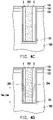
- FIG. 5 is a schematic cross-sectional view illustrating a semiconductor device according to some embodiments of the present disclosure.
- step S 100 is performed, and a substrate 100 is provided.
- the substrate 100 is a semiconductor substrate.
- Step S 102 is performed, and a hard mask pattern 102 is formed over the substrate 100 .
- the hard mask pattern 102 has an opening W. Although only a single opening W is depicted in FIG. 2A , the hard mask pattern 102 may actually have more than one openings W.
- the opening W is formed for defining location, dimension and shape of a recess RS to be formed in the subsequent step (as shown in FIG. 2B ).
- the opening W may be formed in a stripe shape, such that the subsequently formed recess RS could be a trench in a stripe shape.
- step S 104 is performed, and a portion of the substrate 100 exposed by the hard mask pattern 102 is removed, so as to form the recess RS.
- an etching process e.g., an anisotropic etching process
- a sidewall of the recess RS may be substantially coplanar with a sidewall of the opening W of the hard mask pattern 102 .
- step S 106 is performed, and a channel layer 104 and a barrier layer 106 are sequentially formed.
- a top surface of the hard mask pattern 102 , a sidewall of the hard mask pattern 102 and a surface of the recess RS of the substrate 100 are covered by the channel layer 104
- a surface of the channel layer 104 is covered by the barrier layer 106 .
- a method for forming the channel layer 104 and a method for forming the barrier layer 106 may respectively include an epitaxial process.
- Materials of the channel layer 104 and the barrier layer 106 may respectively include a group III nitride or a group III-V compound semiconductor material.
- the material of the channel layer 104 may include GaN, GaAs, the like or combinations thereof
- the material of the barrier layer 106 may include InAlGaN, AlGaN, AlInN, AN, the like or combinations thereof.
- a hetero junction formed by the channel layer 104 and the barrier layer 106 may induce a spontaneous polarization effect and a piezoelectric polarization effect, and two dimensional electron gas (2DEG) or two dimensional hole gas (2DHG) may be generated in the vicinity of an interface between the channel layer 104 and the barrier layer 106 .
- the hetero junction formed by the channel layer 104 and the barrier layer 106 may be functioned as an active region of a high electron mobility transistor (HEMT) or a high hole mobility transistor (HHMT).
- a thickness of the channel layer 104 and a thickness of the barrier layer 106 may respectively range from 3 nm to 50 nm. In these embodiments, the thickness of the barrier layer 106 is large enough for forming continuously extending 2DEG or 2DHG in the vicinity of the interface between the channel layer 104 and the barrier layer 106 .
- step S 108 is performed, and a horizontally extending portion 106 a of the barrier layer 106 are thinned.
- the barrier layer 106 has a horizontally extending portions 106 a and a vertically extending portions 106 b .
- the top surface of the hard mask pattern 102 and a bottom surface of the recess RS are covered by the horizontally extending portion 106 a
- the sidewall of the hard mask pattern 102 and the sidewall of the recess RS are covered by the vertically extending portion 106 b .
- a skin part of the horizontally extending portion 106 a may be removed by an anisotropic etching process, such that the horizontally extending portion 106 a could be thinned.
- the vertically extending portion 106 b of the barrier layer 106 is not subjected to the thinning process, and the thickness of the barrier layer 106 b may remain unchanged. In this way, the thickness of the horizontally extending portion 106 a has become less than the thickness of the vertically extending portion 106 b .
- the current thickness T 106a of the horizontally extending portion 106 a may range from 2 nm to 49 nm, whereas the thickness T 106b of the vertically extending portion 106 b may range from 3 nm to 50 nm.
- the thickness T 106a of the vertically extending portion 106 a of the barrier layer 106 has become less than the thickness of the channel layer 104 , portions of the 2DEG or 2DHG formed in the vicinity of the interface between the horizontally extending portion 106 a and the channel layer 104 no longer exist.
- the vertically extending portion 106 b of the barrier layer 106 is not subjected to the thinning process, portions of the 2DEG or 2DHG in the vicinity of the interface between the vertically extending portion 106 b and the channel layer 104 would remain. Accordingly, when the hetero junction formed by the barrier layer 104 and the channel layer 104 is unbiased, the 2DEG or 2DHG is continuous along a vertical direction, but discontinuous along a horizontal direction. Therefore, the hetero junction made by the barrier layer 106 and the channel layer 104 can be functioned as an active region of an enhance mode HEMT/HHMT (or referred as a normally-off HEMT/HHMT).
- an enhance mode HEMT/HHMT or referred as a normally-off HEMT/HHMT
- step S 110 is performed, and a gate material layer 108 is formed.
- the structure as shown in FIG. 2D may be globally covered by the gate material layer 108 , and the gate material layer 108 may extend into the recess RS. Accordingly, the horizontally extending portion 106 a and the vertically extending portion 106 b of the barrier layer 106 are both covered by the gate material layer 108 .
- the recess RS is filled up by the gate material layer 108 .
- a material of the gate material layer 108 may include a metal, a metal nitride, a metal silicide or other materials that could form schottky contact with the barrier layer 106 .
- a method for forming the gate material layer 108 may include a chemical vapor deposition (CVD) process, a physical vapor deposition process (PVD), the like or combinations thereof.
- step S 112 is performed, and some portions of the gate material layer 108 are removed, to form a gate electrode 110 .
- a portion of the gate material layer 108 above a topmost surface of the substrate 100 and another portion of the gate material layer 108 located in an upper part of the recess RS are removed, and the remained portion of the gate material layer 108 forms the gate electrode 110 .
- a top surface of the gate electrode 110 may be lower than the topmost surface of the substrate 100 .
- a method for removing the portions of the gate material layer 108 may include an etching process, a chemical mechanical polishing (CMP) process or a combination thereof.
- CMP chemical mechanical polishing
- step S 114 is performed, and an insulating structure 112 is formed on the gate electrode 110 .
- a method for forming the insulating structure 112 includes forming an insulating material layer (not shown) over the structure shown in FIG. 2F by a CVD process, and removing some portions of the insulating material layer to form the insulating structure 112 .
- the insulating structure 112 extends upwardly from the gate electrode 110 , and a top surface of the insulating structure 112 is lower than a topmost surface of the barrier layer 106 .
- the top surface of the insulating structure 112 is higher than the topmost surface of the substrate 100 , and may be lower than, coplanar with or higher than the top surface of the hard mask pattern 102 .
- a height difference between the top surface of the insulating structure 112 and the topmost surface of the barrier layer 106 may range from 30 nm to 60 nm.
- a material of the insulating structure 112 may include silicon oxide, silicon nitride or a combination thereof.
- step S 116 is performed, and a mask structure 114 is formed on the insulating structure 112 .
- a top surface of the mask structure 114 may be substantially coplanar with the topmost surface of the barrier layer 106 .
- a thickness T 114 of the mask structure 114 may range from 30 nm to 60 nm.
- a material of the mask structure 114 has sufficient etching selectivity with respect to the material of the insulating structure 112 .
- the material of the insulating structure 112 includes silicon nitride, whereas the mask structure 114 includes silicon oxide.
- step S 118 is performed, and a portion of the barrier layer 106 above the hard mask pattern 102 is removed.
- the barrier layer 106 may be etched by using the mask structure 114 as a shadow mask.
- the hard mask pattern 102 may be functioned as an etching stop layer during the etching process performed on the barrier layer 106 , such that the portion of the barrier layer 106 above the hard mask pattern 102 can be removed.
- top surfaces of the hard mask pattern 102 , the channel layer 104 and the barrier layer 106 may be substantially coplanar with one another.
- step S 120 is performed, and a drain electrode 116 and a source electrode 118 are formed at opposite sides of the mask structure 114 .
- a method for forming the drain electrode 116 and the source electrode 118 includes forming a conductive material layer (not shown) on the structure shown in FIG. 2I .
- the top surface of the hard mask pattern 102 , the top surface of the channel layer 104 , the top surface of the barrier layer 106 and the top surface of the mask structure 114 are covered by this conductive material layer.
- a planarization process (such as a CMP process) is performed on the conductive material layer, and the mask structure 114 may be functioned as a stop layer during the planarization process.
- the planarized conductive material layer may be patterned to form the drain electrode 116 and the source electrode 118 .
- the drain electrode 116 and the source electrode 118 are separated from each other, and cover portions of the barrier layer 106 , the channel layer 104 and the hard mask pattern 102 located at opposite sides of the mask structure 114 .
- a material of the drain electrode 116 and the source electrode 118 includes a metal or any material that could form ohmic contact with the barrier layer 106 .
- a thickness of the drain electrode 116 and the source electrode 118 may be substantially equal to the thickness T 114 of the mask structure 114 , and may range from, for example, 30 nm to 60 nm.
- step S 122 is performed, and the mask structure 114 is removed.
- the mask structure 114 may be removed by an etching process (e.g., an isotropic etching process or an anisotropic etching process). Since the material of the mask structure 114 may have sufficient etching selectivity with respect to the material of the insulating structure 112 , the insulating structure 112 may be functioned as an etching stop layer during the etching process performed on the mask structure 114 . Once the mask structure 114 has been removed, the top surface of the insulating structure 112 and opposing sidewalls of the drain electrode 116 and the source electrode 118 may be exposed.
- an etching process e.g., an isotropic etching process or an anisotropic etching process
- step S 124 is performed, and another insulating structure 120 is formed over the insulating structure 112 .
- a top surface of the insulating structure 120 may be substantially coplanar with top surfaces of the drain electrode 116 and the source electrode 118 .
- a material of the insulating structure 120 may include silicon oxide, silicon nitride, the like or combinations thereof.
- the semiconductor device 10 may be an embedded type HEMT/HHMT, and is at least partially formed in the recess of the substrate 100 .
- the gate electrode 110 does not receive a gate voltage or the gate voltage received by the gate electrode 110 is less than a threshold value, the 2DEG or 2DHG in the hetero junction formed by the channel layer 104 and the barrier layer 106 is discontinuous, such that the semiconductor device 10 is in an off state.
- the gate voltage received by the gate electrode 110 is greater than the threshold value, the 2DEG or 2DHG in the hetero junction formed by the channel layer 104 and the barrier layer 106 becomes continuous, and the semiconductor device 10 turns into an on state.
- the semiconductor device 10 may be a portion of a unit cell in a DRAM integrated circuit, and a capacitor structure (not shown) may be further formed on the drain electrode 116 or the source electrode 118 of the semiconductor device 10 .
- a conductive channel of the semiconductor device 10 (i.e., the 2DEG/2DHG as described above) is formed inside the recess RS of the substrate 100 , rather than being formed in a portion of the substrate 100 close to the recess RS of the substrate 100 .
- charges in the conductive channel can be avoided from moving to the drain electrode 116 or the source electrode 118 through a path in the substrate 100 , thus formation of sneak current can be avoided. Therefore, reliability of the semiconductor device 10 can be improved.
- charges can be avoided from moving between the semiconductor device 10 and adjacent devices along paths in the substrate 100 . As such, interference between the semiconductor device 10 and other devices can be reduced.
- the semiconductor device 10 includes the hard mask pattern 102 .
- the hard mask pattern 102 is disposed between the drain electrode 116 and the substrate 100 , and between the source electrode 118 and the substrate. Charges can be further blocked by the hard mask pattern 102 from moving to the drain electrode 116 and the source electrode 118 from the substrate 100 .
- step S 200 is performed after the step S 100 through step S 108 (as shown in FIG. 2A through FIG. 2D ), and a dummy structure 200 is formed on a surface of the vertically extending portion 106 b of the barrier layer 106 .
- a method for forming the dummy structure 200 may include forming a dummy material layer (not shown) globally covering the barrier layer 106 , then performing an anisotropic etching process to remove a horizontally extending portion of the dummy material layer.
- a portion of the dummy material layer covering the horizontally extending portion 106 a of the barrier layer 106 is removed, whereas a portion of the dummy material layer covering the vertically extending portion 106 b of the barrier layer 106 remains and forms the dummy structure 200 .
- a top surface of the dummy structure 200 is substantially coplanar with the topmost surface of the barrier layer 106 .
- a material of the dummy structure 200 may include silicon oxide, silicon nitride, the like or combinations thereof.
- a thickness T 200 of the dummy structure 200 may range from 3 nm to 50 nm.
- step S 202 is performed, and a mask structure 202 is formed in the recess RS of the substrate 100 .
- a top surface of the mask structure 202 may be substantially coplanar with the topmost surfaces of the dummy structure 200 and the barrier layer 106 .
- a material of the mask structure 202 has a sufficient etching selectivity with respect to the material of the dummy structure 200 .
- the material of the mask structure 202 may include silicon nitride, whereas the material of the dummy structure 200 may include silicon oxide.
- step S 204 is performed, and the dummy structure 200 is removed.
- the dummy structure 200 may be removed by an isotropic etching process or an anisotropic etching process.
- a gap G may be formed between the mask structure 202 and the barrier layer 106 .
- the gap G forms a circle in the recess RS, and may surround the mask structure 202 .
- step S 206 is performed, and a first gate electrode 204 and a second gate electrode 206 separated from each other are formed in the recess RS.
- a method for forming the first gate electrode 204 and the second gate electrode 206 may include forming a gate material layer on the structure as shown in FIG. 4C by a CVD process or a PVD process.
- the gate material layer covers the topmost surface of the barrier layer 106 , and fills into the gap G. Thereafter, portions of the gate material layer located above the topmost surface of the barrier layer 106 and in an upper part of the gap G are removed, whereas a portion of the gate material layer located in a bottom part of the gap P is remained.
- a patterning process may be performed on the gate material layer, so as to form the separated first gate electrode 204 and second gate electrode 206 located on opposite sidewalls of the recess RS.
- the first gate electrode 204 and the second gate electrode 206 are separately located in the bottom portion of the gap G, and top surfaces of the first gate electrode 204 and the second gate electrode 206 are lower than the topmost surface of the substrate 100 .
- a thickness T 204 of the first gate electrode 204 and a thickness T 206 of the second gate electrode 206 are substantially equal to each other, and may respectively range from 3 nm to 50 nm.
- a material of the first gate electrode 204 and the second gate electrode 206 may be similar to the material of the gate electrode 110 as described with reference to FIG. 2F .
- step S 208 is performed, and the mask structure 202 is removed.
- the mask structure 202 may be removed by an isotropic etching process or an anisotropic etching process.
- a bottom portion of the barrier layer 106 is exposed, along with the sidewalls of the first gate electrode 204 and the second gate electrode 206 that are facing away from the vertically extending portion 106 b of the barrier layer 106 .
- step S 210 is performed, and a channel layer 208 and a barrier layer 210 are sequentially formed.
- the channel layer 208 and the barrier layer 210 may be referred as a second channel layer and a second barrier layer, whereas the previously formed channel layer 104 and the barrier layer 106 may be referred as a first channel layer and a first barrier layer.
- the channel layer 208 and the barrier layer 210 are sequentially and conformally formed on the structure shown in FIG. 4E . In other words, exposed surfaces of the barrier layer 106 , the first gate electrode 204 and the second gate electrode 206 are covered by the channel layer 208 , and the channel layer 208 is covered by the barrier layer 210 .
- the channel layer 208 and the barrier layer 210 are similar to the materials and the formation methods of the channel layer 104 and the barrier layer 106 .
- the channel layer 208 and the barrier layer 210 may form another hetero junction.
- the first gate electrode 204 is located between two hetero junctions.
- the second gate electrode 206 is located between these two hetero junctions. Accordingly, both of the first gate electrode 204 and the second gate electrode 206 can be configured to receive gate voltages for controlling these two hetero junctions.
- step S 212 is performed, and a horizontally extending portion 210 a of the barrier layer 210 is thinned.
- This step i.e., the step S 212
- step S 214 is performed, and an insulating structure 212 is formed.
- the insulating structure 212 fills in a recess defined by a bottom portion and a vertically extending portion 210 b of the barrier layer 210 .
- the insulating structure 212 has a bottom portion between the first gate electrode 204 and the second gate electrode 206 , and has a top portion over the bottom portion.
- the bottom portion of the insulating structure 212 has a width less than a width of the top portion of the insulating structure 212 .
- a top surface of the insulating structure 212 is lower than a topmost surface of the barrier layer 210 .
- the top surface of the insulating structure 212 may be higher than the topmost surface of the substrate 100 , and may be lower than, coplanar with or higher than the top surface of the hard mask pattern 102 .
- a thickness T 212 of the insulating structure 212 may range from 3 nm to 60 nm.
- a material and a formation method of the insulating structure 212 may be similar to the material and the formation method of the insulating structure 112 as described with reference to FIG. 2G , and would not be repeated again.
- step S 216 is performed, and a mask structure 214 is formed over the insulating structure 212 .
- the mask structure 214 fills in a recess defined by the vertically extending portion 210 b of the barrier layer 210 and the top surface of the insulating structure 212 .
- This step i.e., the step S 216
- step S 218 is performed, and portions of the channel layer 104 , the barrier layer 106 , the channel layer 208 and the barrier layer 210 above the hard mask pattern 102 are removed.
- top surfaces of the hard mask pattern 102 , the channel layer 104 , the barrier layer 106 , the channel layer 208 and the barrier layer 210 may be substantially coplanar with one another.
- step S 220 is performed, and a drain electrode 216 and a source electrode 218 are formed at opposite sides of the mask structure 214 .
- the drain electrode 216 and the source electrode 218 are separated from each other, and cover portions of the barrier layer 210 , the channel layer 208 , the barrier layer 106 , the channel layer 104 and the hard mask pattern 102 located at opposite sides of the mask structure 214 .
- a material, a thickness and a formation method of the drain electrode 216 and the source electrode 218 are similar to those of the drain electrode 116 and the source electrode 118 as described with reference to FIG. 2J , and would not be repeated again.
- step S 222 is performed, and the mask structure 214 is removed. Once the mask structure 214 has been removed, the top surface of the insulating structure 212 and opposing sidewalls of the drain electrode 216 and the source electrode 218 may be exposed.
- step S 224 is performed, and another insulating structure 220 is formed over the insulating structure 212 .
- the insulating structure 220 fills in a recess defined by the top surface of the insulating structure 212 and the sidewalls of the drain electrode 216 and the source electrode 218 .
- the semiconductor device 20 includes the hetero junction formed by the channel layer 104 and the barrier layer 106 , and further includes the hetero junction formed by the channel layer 208 and the barrier layer 210 .
- the first gate electrode 204 and the second gate electrode 206 are separately located between these two hetero junctions, and may be configured to receive voltages for controlling the 2DEG/2DHG formed in these two hetero junctions.
- a semiconductor device 30 as shown in FIG. 5 is similar to the semiconductor device 20 as shown in FIG. 4K , except that the channel layer 208 and the barrier 210 as shown in FIG. 4K are omitted from the semiconductor device 30 as shown in FIG. 5 .
- the insulating structure 212 may be in contact with the barrier layer 106 , the first gate electrode 204 and the second gate electrode 206 .
- the insulating structure 220 is located over the insulating structure 212 , and may be in contact with the barrier layer 106 and sidewalls of the drain electrode 216 and the source electrode 218 .
- the semiconductor device is an embedded type semiconductor device.
- a conductive channel of the semiconductor device i.e., the 2DEG/2DHG as described above
- the semiconductor device includes the hard mask pattern. The hard mask pattern is disposed between the drain electrode and the substrate, and between the source electrode and the substrate. Charges can be further blocked by the hard mask pattern from moving to the drain electrode and the source electrode from the substrate.
Abstract
Description
Claims (13)
Priority Applications (2)
| Application Number | Priority Date | Filing Date | Title |
|---|---|---|---|
| US16/681,704 US11367787B2 (en) | 2019-11-12 | 2019-11-12 | Semiconductor device and manufacturing method thereof |
| US17/739,210 US11923449B2 (en) | 2019-11-12 | 2022-05-09 | Manufacturing method for semiconductor device |
Applications Claiming Priority (1)
| Application Number | Priority Date | Filing Date | Title |
|---|---|---|---|
| US16/681,704 US11367787B2 (en) | 2019-11-12 | 2019-11-12 | Semiconductor device and manufacturing method thereof |
Related Child Applications (1)
| Application Number | Title | Priority Date | Filing Date |
|---|---|---|---|
| US17/739,210 Division US11923449B2 (en) | 2019-11-12 | 2022-05-09 | Manufacturing method for semiconductor device |
Publications (2)
| Publication Number | Publication Date |
|---|---|
| US20210143270A1 US20210143270A1 (en) | 2021-05-13 |
| US11367787B2 true US11367787B2 (en) | 2022-06-21 |
Family
ID=75847873
Family Applications (2)
| Application Number | Title | Priority Date | Filing Date |
|---|---|---|---|
| US16/681,704 Active US11367787B2 (en) | 2019-11-12 | 2019-11-12 | Semiconductor device and manufacturing method thereof |
| US17/739,210 Active 2040-02-29 US11923449B2 (en) | 2019-11-12 | 2022-05-09 | Manufacturing method for semiconductor device |
Family Applications After (1)
| Application Number | Title | Priority Date | Filing Date |
|---|---|---|---|
| US17/739,210 Active 2040-02-29 US11923449B2 (en) | 2019-11-12 | 2022-05-09 | Manufacturing method for semiconductor device |
Country Status (1)
| Country | Link |
|---|---|
| US (2) | US11367787B2 (en) |
Citations (11)
| Publication number | Priority date | Publication date | Assignee | Title |
|---|---|---|---|---|
| US20050145883A1 (en) * | 2003-12-05 | 2005-07-07 | Robert Beach | III-nitride semiconductor device with trench structure |
| US7098093B2 (en) * | 2004-09-13 | 2006-08-29 | Northrop Grumman Corporation | HEMT device and method of making |
| US20090140295A1 (en) * | 2007-11-16 | 2009-06-04 | Shusuke Kaya | GaN-based semiconductor device and method of manufacturing the same |
| US20100025730A1 (en) * | 2008-07-31 | 2010-02-04 | Cree, Inc. | Normally-off Semiconductor Devices and Methods of Fabricating the Same |
| US20120305987A1 (en) | 2011-06-03 | 2012-12-06 | Infineon Technologies Austria Ag | Lateral trench mesfet |
| US20160172488A1 (en) * | 2014-12-16 | 2016-06-16 | SK Hynix Inc. | Semiconductor device having dual work function gate structure, method for fabricating the same, transistor circuit having the same, memory cell having the same, and electronic device having the same |
| US20170148906A1 (en) * | 2015-11-24 | 2017-05-25 | Stmicroelectronics S.R.L. | Normally-off transistor with reduced on-state resistance and manufacturing method |
| US20170345921A1 (en) * | 2016-05-30 | 2017-11-30 | Epistar Corporation | Power device and method for fabricating thereof |
| US20180294335A1 (en) * | 2017-04-07 | 2018-10-11 | University Of Electronic Science And Technology Of China | Polarization-doped enhancement mode hemt |
| US20180374952A1 (en) * | 2012-05-23 | 2018-12-27 | Hrl Laboratories, Llc | HEMT GaN DEVICE WITH A NON-UNIFORM LATERAL TWO DIMENSIONAL ELECTRON GAS PROFILE AND METHOD OF MANUFACTURING THE SAME |
| US20190081164A1 (en) * | 2017-07-12 | 2019-03-14 | Indian Institute Of Science | A High-electron-mobility transistor (HEMT) |
Family Cites Families (12)
| Publication number | Priority date | Publication date | Assignee | Title |
|---|---|---|---|---|
| US7652326B2 (en) | 2003-05-20 | 2010-01-26 | Fairchild Semiconductor Corporation | Power semiconductor devices and methods of manufacture |
| KR101417764B1 (en) | 2008-09-26 | 2014-07-09 | 삼성전자주식회사 | Vertical semiconductor device and method for manufacturing the same |
| KR20140145434A (en) * | 2013-06-13 | 2014-12-23 | 삼성전자주식회사 | Semiconductor device and method for fabricating the same |
| KR102055333B1 (en) | 2014-01-29 | 2020-01-22 | 에스케이하이닉스 주식회사 | Dual work function bruied gate type transistor, method for manufacturing the same and electronic device having the same |
| KR102336033B1 (en) * | 2015-04-22 | 2021-12-08 | 에스케이하이닉스 주식회사 | Semiconductor device having buried gate structure and method for manufacturing the same, memory cell having the same and electronic device having the same |
| US10224401B2 (en) * | 2016-05-31 | 2019-03-05 | Transphorm Inc. | III-nitride devices including a graded depleting layer |
| US9837507B1 (en) | 2016-09-30 | 2017-12-05 | Taiwan Semiconductor Manufacturing Co., Ltd. | Semiconductor device and manufacturing method thereof |
| KR102511942B1 (en) | 2016-12-16 | 2023-03-23 | 에스케이하이닉스 주식회사 | Semiconductor device having buried gate structure and method for manufacturing the same |
| TWI722166B (en) | 2017-04-10 | 2021-03-21 | 聯穎光電股份有限公司 | High electron mobility transistor |
| TWI655750B (en) | 2017-06-06 | 2019-04-01 | 旺宏電子股份有限公司 | Memory device and method for fabricating the same |
| US10714598B2 (en) | 2017-06-30 | 2020-07-14 | Taiwan Semiconductor Manufacturing Co., Ltd. | Method of manufacturing semiconductor device |
| JP6957536B2 (en) * | 2019-01-04 | 2021-11-02 | 株式会社東芝 | Semiconductor devices, inverter circuits, drives, vehicles, and elevators |
-
2019
- 2019-11-12 US US16/681,704 patent/US11367787B2/en active Active
-
2022
- 2022-05-09 US US17/739,210 patent/US11923449B2/en active Active
Patent Citations (11)
| Publication number | Priority date | Publication date | Assignee | Title |
|---|---|---|---|---|
| US20050145883A1 (en) * | 2003-12-05 | 2005-07-07 | Robert Beach | III-nitride semiconductor device with trench structure |
| US7098093B2 (en) * | 2004-09-13 | 2006-08-29 | Northrop Grumman Corporation | HEMT device and method of making |
| US20090140295A1 (en) * | 2007-11-16 | 2009-06-04 | Shusuke Kaya | GaN-based semiconductor device and method of manufacturing the same |
| US20100025730A1 (en) * | 2008-07-31 | 2010-02-04 | Cree, Inc. | Normally-off Semiconductor Devices and Methods of Fabricating the Same |
| US20120305987A1 (en) | 2011-06-03 | 2012-12-06 | Infineon Technologies Austria Ag | Lateral trench mesfet |
| US20180374952A1 (en) * | 2012-05-23 | 2018-12-27 | Hrl Laboratories, Llc | HEMT GaN DEVICE WITH A NON-UNIFORM LATERAL TWO DIMENSIONAL ELECTRON GAS PROFILE AND METHOD OF MANUFACTURING THE SAME |
| US20160172488A1 (en) * | 2014-12-16 | 2016-06-16 | SK Hynix Inc. | Semiconductor device having dual work function gate structure, method for fabricating the same, transistor circuit having the same, memory cell having the same, and electronic device having the same |
| US20170148906A1 (en) * | 2015-11-24 | 2017-05-25 | Stmicroelectronics S.R.L. | Normally-off transistor with reduced on-state resistance and manufacturing method |
| US20170345921A1 (en) * | 2016-05-30 | 2017-11-30 | Epistar Corporation | Power device and method for fabricating thereof |
| US20180294335A1 (en) * | 2017-04-07 | 2018-10-11 | University Of Electronic Science And Technology Of China | Polarization-doped enhancement mode hemt |
| US20190081164A1 (en) * | 2017-07-12 | 2019-03-14 | Indian Institute Of Science | A High-electron-mobility transistor (HEMT) |
Also Published As
| Publication number | Publication date |
|---|---|
| US20210143270A1 (en) | 2021-05-13 |
| US11923449B2 (en) | 2024-03-05 |
| US20220262943A1 (en) | 2022-08-18 |
Similar Documents
| Publication | Publication Date | Title |
|---|---|---|
| US7368769B2 (en) | MOS transistor having a recessed gate electrode and fabrication method thereof | |
| US8624350B2 (en) | Semiconductor device and method of fabricating the same | |
| CN103456781B (en) | Compound semiconductor transistor with self aligned gate | |
| US8299517B2 (en) | Semiconductor device employing transistor having recessed channel region and method of fabricating the same | |
| US8507349B2 (en) | Semiconductor device employing fin-type gate and method for manufacturing the same | |
| KR101087895B1 (en) | Semiconductor apparatus and fabrication method thereof | |
| US8580669B2 (en) | Method for fabricating semiconductor device | |
| US9570391B2 (en) | Semiconductor device and method for manufacturing the same | |
| KR20170043683A (en) | Method for manufaturing semiconductor device | |
| US7514330B2 (en) | Semiconductor device having an under stepped gate for preventing gate failure and method of manufacturing the same | |
| US7303963B2 (en) | Method for manufacturing cell transistor | |
| US20110263089A1 (en) | Method for fabricating semiconductor device | |
| US20100203696A1 (en) | Semiconductor device and method for manufacturing the same | |
| US9269819B2 (en) | Semiconductor device having a gate and a conductive line in a pillar pattern | |
| CN107369621B (en) | Fin field effect transistor and forming method thereof | |
| KR101159985B1 (en) | Semiconductor device and method for manufacturing the same | |
| CN112582413B (en) | Semiconductor device and method for manufacturing the same | |
| US20130146966A1 (en) | Semiconductor structure with enhanced cap and fabrication method thereof | |
| US11367787B2 (en) | Semiconductor device and manufacturing method thereof | |
| CN115020484A (en) | Semiconductor device having gate trench | |
| TWI704674B (en) | Semiconductor device and manufacturing method thereof | |
| KR100668741B1 (en) | Gate of semiconductor device and forming process thereof | |
| US20230132891A1 (en) | Method for Manufacturing Isolation Structure of Hybrid Epitaxial Area and Active Area in FDSOI | |
| US11316043B2 (en) | Semiconductor transistor device and method of manufacturing the same | |
| US20240074152A1 (en) | Semiconductor structure and manufacturing method therof |
Legal Events
| Date | Code | Title | Description |
|---|---|---|---|
| AS | Assignment |
Owner name: WINBOND ELECTRONICS CORP., TAIWAN Free format text: ASSIGNMENT OF ASSIGNORS INTEREST;ASSIGNORS:CHANG, HAO-CHUAN;JEN, KAI;REEL/FRAME:050987/0439 Effective date: 20191104 |
|
| FEPP | Fee payment procedure |
Free format text: ENTITY STATUS SET TO UNDISCOUNTED (ORIGINAL EVENT CODE: BIG.); ENTITY STATUS OF PATENT OWNER: LARGE ENTITY |
|
| STPP | Information on status: patent application and granting procedure in general |
Free format text: RESPONSE TO NON-FINAL OFFICE ACTION ENTERED AND FORWARDED TO EXAMINER |
|
| STPP | Information on status: patent application and granting procedure in general |
Free format text: FINAL REJECTION MAILED |
|
| STPP | Information on status: patent application and granting procedure in general |
Free format text: RESPONSE AFTER FINAL ACTION FORWARDED TO EXAMINER |
|
| STPP | Information on status: patent application and granting procedure in general |
Free format text: ADVISORY ACTION MAILED |
|
| STPP | Information on status: patent application and granting procedure in general |
Free format text: DOCKETED NEW CASE - READY FOR EXAMINATION |
|
| STPP | Information on status: patent application and granting procedure in general |
Free format text: NOTICE OF ALLOWANCE MAILED -- APPLICATION RECEIVED IN OFFICE OF PUBLICATIONS |
|
| STPP | Information on status: patent application and granting procedure in general |
Free format text: PUBLICATIONS -- ISSUE FEE PAYMENT RECEIVED |
|
| STPP | Information on status: patent application and granting procedure in general |
Free format text: PUBLICATIONS -- ISSUE FEE PAYMENT VERIFIED |
|
| STCF | Information on status: patent grant |
Free format text: PATENTED CASE |