US11309560B2 - Method of predicting life of membrane electrode assembly of fuel cell for electric power generation - Google Patents
Method of predicting life of membrane electrode assembly of fuel cell for electric power generation Download PDFInfo
- Publication number
- US11309560B2 US11309560B2 US16/824,898 US202016824898A US11309560B2 US 11309560 B2 US11309560 B2 US 11309560B2 US 202016824898 A US202016824898 A US 202016824898A US 11309560 B2 US11309560 B2 US 11309560B2
- Authority
- US
- United States
- Prior art keywords
- degradation
- fuel cell
- under
- degree
- operating condition
- Prior art date
- Legal status (The legal status is an assumption and is not a legal conclusion. Google has not performed a legal analysis and makes no representation as to the accuracy of the status listed.)
- Active, expires
Links
Images


Classifications
-
- H—ELECTRICITY
- H01—ELECTRIC ELEMENTS
- H01M—PROCESSES OR MEANS, e.g. BATTERIES, FOR THE DIRECT CONVERSION OF CHEMICAL ENERGY INTO ELECTRICAL ENERGY
- H01M8/00—Fuel cells; Manufacture thereof
- H01M8/04—Auxiliary arrangements, e.g. for control of pressure or for circulation of fluids
- H01M8/04298—Processes for controlling fuel cells or fuel cell systems
- H01M8/04313—Processes for controlling fuel cells or fuel cell systems characterised by the detection or assessment of variables; characterised by the detection or assessment of failure or abnormal function
- H01M8/04537—Electric variables
- H01M8/04544—Voltage
- H01M8/04552—Voltage of the individual fuel cell
-
- H—ELECTRICITY
- H01—ELECTRIC ELEMENTS
- H01M—PROCESSES OR MEANS, e.g. BATTERIES, FOR THE DIRECT CONVERSION OF CHEMICAL ENERGY INTO ELECTRICAL ENERGY
- H01M8/00—Fuel cells; Manufacture thereof
- H01M8/04—Auxiliary arrangements, e.g. for control of pressure or for circulation of fluids
- H01M8/04298—Processes for controlling fuel cells or fuel cell systems
- H01M8/04313—Processes for controlling fuel cells or fuel cell systems characterised by the detection or assessment of variables; characterised by the detection or assessment of failure or abnormal function
- H01M8/04664—Failure or abnormal function
-
- G—PHYSICS
- G01—MEASURING; TESTING
- G01R—MEASURING ELECTRIC VARIABLES; MEASURING MAGNETIC VARIABLES
- G01R31/00—Arrangements for testing electric properties; Arrangements for locating electric faults; Arrangements for electrical testing characterised by what is being tested not provided for elsewhere
- G01R31/36—Arrangements for testing, measuring or monitoring the electrical condition of accumulators or electric batteries, e.g. capacity or state of charge [SoC]
- G01R31/367—Software therefor, e.g. for battery testing using modelling or look-up tables
-
- H—ELECTRICITY
- H01—ELECTRIC ELEMENTS
- H01M—PROCESSES OR MEANS, e.g. BATTERIES, FOR THE DIRECT CONVERSION OF CHEMICAL ENERGY INTO ELECTRICAL ENERGY
- H01M8/00—Fuel cells; Manufacture thereof
- H01M8/04—Auxiliary arrangements, e.g. for control of pressure or for circulation of fluids
- H01M8/04298—Processes for controlling fuel cells or fuel cell systems
- H01M8/04313—Processes for controlling fuel cells or fuel cell systems characterised by the detection or assessment of variables; characterised by the detection or assessment of failure or abnormal function
- H01M8/0432—Temperature; Ambient temperature
- H01M8/04328—Temperature; Ambient temperature of anode reactants at the inlet or inside the fuel cell
-
- H—ELECTRICITY
- H01—ELECTRIC ELEMENTS
- H01M—PROCESSES OR MEANS, e.g. BATTERIES, FOR THE DIRECT CONVERSION OF CHEMICAL ENERGY INTO ELECTRICAL ENERGY
- H01M8/00—Fuel cells; Manufacture thereof
- H01M8/04—Auxiliary arrangements, e.g. for control of pressure or for circulation of fluids
- H01M8/04298—Processes for controlling fuel cells or fuel cell systems
- H01M8/04313—Processes for controlling fuel cells or fuel cell systems characterised by the detection or assessment of variables; characterised by the detection or assessment of failure or abnormal function
- H01M8/0438—Pressure; Ambient pressure; Flow
- H01M8/04388—Pressure; Ambient pressure; Flow of anode reactants at the inlet or inside the fuel cell
-
- H—ELECTRICITY
- H01—ELECTRIC ELEMENTS
- H01M—PROCESSES OR MEANS, e.g. BATTERIES, FOR THE DIRECT CONVERSION OF CHEMICAL ENERGY INTO ELECTRICAL ENERGY
- H01M8/00—Fuel cells; Manufacture thereof
- H01M8/04—Auxiliary arrangements, e.g. for control of pressure or for circulation of fluids
- H01M8/04298—Processes for controlling fuel cells or fuel cell systems
- H01M8/04313—Processes for controlling fuel cells or fuel cell systems characterised by the detection or assessment of variables; characterised by the detection or assessment of failure or abnormal function
- H01M8/04492—Humidity; Ambient humidity; Water content
- H01M8/045—Humidity; Ambient humidity; Water content of anode reactants at the inlet or inside the fuel cell
-
- H—ELECTRICITY
- H01—ELECTRIC ELEMENTS
- H01M—PROCESSES OR MEANS, e.g. BATTERIES, FOR THE DIRECT CONVERSION OF CHEMICAL ENERGY INTO ELECTRICAL ENERGY
- H01M8/00—Fuel cells; Manufacture thereof
- H01M8/04—Auxiliary arrangements, e.g. for control of pressure or for circulation of fluids
- H01M8/04298—Processes for controlling fuel cells or fuel cell systems
- H01M8/04313—Processes for controlling fuel cells or fuel cell systems characterised by the detection or assessment of variables; characterised by the detection or assessment of failure or abnormal function
- H01M8/04537—Electric variables
- H01M8/04544—Voltage
- H01M8/04559—Voltage of fuel cell stacks
-
- H—ELECTRICITY
- H01—ELECTRIC ELEMENTS
- H01M—PROCESSES OR MEANS, e.g. BATTERIES, FOR THE DIRECT CONVERSION OF CHEMICAL ENERGY INTO ELECTRICAL ENERGY
- H01M8/00—Fuel cells; Manufacture thereof
- H01M8/04—Auxiliary arrangements, e.g. for control of pressure or for circulation of fluids
- H01M8/04298—Processes for controlling fuel cells or fuel cell systems
- H01M8/04313—Processes for controlling fuel cells or fuel cell systems characterised by the detection or assessment of variables; characterised by the detection or assessment of failure or abnormal function
- H01M8/04537—Electric variables
- H01M8/04574—Current
- H01M8/04582—Current of the individual fuel cell
-
- H—ELECTRICITY
- H01—ELECTRIC ELEMENTS
- H01M—PROCESSES OR MEANS, e.g. BATTERIES, FOR THE DIRECT CONVERSION OF CHEMICAL ENERGY INTO ELECTRICAL ENERGY
- H01M8/00—Fuel cells; Manufacture thereof
- H01M8/04—Auxiliary arrangements, e.g. for control of pressure or for circulation of fluids
- H01M8/04298—Processes for controlling fuel cells or fuel cell systems
- H01M8/04313—Processes for controlling fuel cells or fuel cell systems characterised by the detection or assessment of variables; characterised by the detection or assessment of failure or abnormal function
- H01M8/04537—Electric variables
- H01M8/04574—Current
- H01M8/04589—Current of fuel cell stacks
-
- H—ELECTRICITY
- H01—ELECTRIC ELEMENTS
- H01M—PROCESSES OR MEANS, e.g. BATTERIES, FOR THE DIRECT CONVERSION OF CHEMICAL ENERGY INTO ELECTRICAL ENERGY
- H01M8/00—Fuel cells; Manufacture thereof
- H01M8/04—Auxiliary arrangements, e.g. for control of pressure or for circulation of fluids
- H01M8/04298—Processes for controlling fuel cells or fuel cell systems
- H01M8/04313—Processes for controlling fuel cells or fuel cell systems characterised by the detection or assessment of variables; characterised by the detection or assessment of failure or abnormal function
- H01M8/04537—Electric variables
- H01M8/04634—Other electric variables, e.g. resistance or impedance
- H01M8/04641—Other electric variables, e.g. resistance or impedance of the individual fuel cell
-
- H—ELECTRICITY
- H01—ELECTRIC ELEMENTS
- H01M—PROCESSES OR MEANS, e.g. BATTERIES, FOR THE DIRECT CONVERSION OF CHEMICAL ENERGY INTO ELECTRICAL ENERGY
- H01M8/00—Fuel cells; Manufacture thereof
- H01M8/04—Auxiliary arrangements, e.g. for control of pressure or for circulation of fluids
- H01M8/04298—Processes for controlling fuel cells or fuel cell systems
- H01M8/04313—Processes for controlling fuel cells or fuel cell systems characterised by the detection or assessment of variables; characterised by the detection or assessment of failure or abnormal function
- H01M8/04537—Electric variables
- H01M8/04634—Other electric variables, e.g. resistance or impedance
- H01M8/04649—Other electric variables, e.g. resistance or impedance of fuel cell stacks
-
- H—ELECTRICITY
- H01—ELECTRIC ELEMENTS
- H01M—PROCESSES OR MEANS, e.g. BATTERIES, FOR THE DIRECT CONVERSION OF CHEMICAL ENERGY INTO ELECTRICAL ENERGY
- H01M8/00—Fuel cells; Manufacture thereof
- H01M8/04—Auxiliary arrangements, e.g. for control of pressure or for circulation of fluids
- H01M8/04298—Processes for controlling fuel cells or fuel cell systems
- H01M8/04313—Processes for controlling fuel cells or fuel cell systems characterised by the detection or assessment of variables; characterised by the detection or assessment of failure or abnormal function
- H01M8/04664—Failure or abnormal function
- H01M8/04671—Failure or abnormal function of the individual fuel cell
-
- H—ELECTRICITY
- H01—ELECTRIC ELEMENTS
- H01M—PROCESSES OR MEANS, e.g. BATTERIES, FOR THE DIRECT CONVERSION OF CHEMICAL ENERGY INTO ELECTRICAL ENERGY
- H01M8/00—Fuel cells; Manufacture thereof
- H01M8/04—Auxiliary arrangements, e.g. for control of pressure or for circulation of fluids
- H01M8/04298—Processes for controlling fuel cells or fuel cell systems
- H01M8/04694—Processes for controlling fuel cells or fuel cell systems characterised by variables to be controlled
- H01M8/04858—Electric variables
- H01M8/04895—Current
- H01M8/0491—Current of fuel cell stacks
-
- H—ELECTRICITY
- H01—ELECTRIC ELEMENTS
- H01M—PROCESSES OR MEANS, e.g. BATTERIES, FOR THE DIRECT CONVERSION OF CHEMICAL ENERGY INTO ELECTRICAL ENERGY
- H01M8/00—Fuel cells; Manufacture thereof
- H01M8/04—Auxiliary arrangements, e.g. for control of pressure or for circulation of fluids
- H01M8/04298—Processes for controlling fuel cells or fuel cell systems
- H01M8/04992—Processes for controlling fuel cells or fuel cell systems characterised by the implementation of mathematical or computational algorithms, e.g. feedback control loops, fuzzy logic, neural networks or artificial intelligence
-
- H—ELECTRICITY
- H01—ELECTRIC ELEMENTS
- H01M—PROCESSES OR MEANS, e.g. BATTERIES, FOR THE DIRECT CONVERSION OF CHEMICAL ENERGY INTO ELECTRICAL ENERGY
- H01M8/00—Fuel cells; Manufacture thereof
- H01M8/10—Fuel cells with solid electrolytes
- H01M8/1004—Fuel cells with solid electrolytes characterised by membrane-electrode assemblies [MEA]
-
- G—PHYSICS
- G01—MEASURING; TESTING
- G01R—MEASURING ELECTRIC VARIABLES; MEASURING MAGNETIC VARIABLES
- G01R31/00—Arrangements for testing electric properties; Arrangements for locating electric faults; Arrangements for electrical testing characterised by what is being tested not provided for elsewhere
- G01R31/36—Arrangements for testing, measuring or monitoring the electrical condition of accumulators or electric batteries, e.g. capacity or state of charge [SoC]
- G01R31/392—Determining battery ageing or deterioration, e.g. state of health
-
- H—ELECTRICITY
- H01—ELECTRIC ELEMENTS
- H01M—PROCESSES OR MEANS, e.g. BATTERIES, FOR THE DIRECT CONVERSION OF CHEMICAL ENERGY INTO ELECTRICAL ENERGY
- H01M8/00—Fuel cells; Manufacture thereof
- H01M8/10—Fuel cells with solid electrolytes
- H01M2008/1095—Fuel cells with polymeric electrolytes
-
- H—ELECTRICITY
- H01—ELECTRIC ELEMENTS
- H01M—PROCESSES OR MEANS, e.g. BATTERIES, FOR THE DIRECT CONVERSION OF CHEMICAL ENERGY INTO ELECTRICAL ENERGY
- H01M2250/00—Fuel cells for particular applications; Specific features of fuel cell system
- H01M2250/10—Fuel cells in stationary systems, e.g. emergency power source in plant
-
- Y—GENERAL TAGGING OF NEW TECHNOLOGICAL DEVELOPMENTS; GENERAL TAGGING OF CROSS-SECTIONAL TECHNOLOGIES SPANNING OVER SEVERAL SECTIONS OF THE IPC; TECHNICAL SUBJECTS COVERED BY FORMER USPC CROSS-REFERENCE ART COLLECTIONS [XRACs] AND DIGESTS
- Y02—TECHNOLOGIES OR APPLICATIONS FOR MITIGATION OR ADAPTATION AGAINST CLIMATE CHANGE
- Y02E—REDUCTION OF GREENHOUSE GAS [GHG] EMISSIONS, RELATED TO ENERGY GENERATION, TRANSMISSION OR DISTRIBUTION
- Y02E60/00—Enabling technologies; Technologies with a potential or indirect contribution to GHG emissions mitigation
- Y02E60/30—Hydrogen technology
- Y02E60/50—Fuel cells
Definitions
- the present disclosure relates to a method of predicting a life of a membrane electrode assembly (MEA) of a fuel cell for electric power generation and, more particularly, to a method of predicting a life of a membrane electrode assembly of a fuel cell for electric power generation using an operating condition for accelerated degradation, which is applicable to the fuel cell.
- MEA membrane electrode assembly
- a fuel cell is a device that generates electric energy by causing hydrogen (H 2 ) and oxygen (O 2 ) to react with each other.
- the fuel cell includes a membrane electrode assembly (MEA).
- the membrane electrode assembly is configured to include an electrolyte membrane to which a hydrogen ion (H) is transferred, an anode that is configured to be stacked on one side of the electrolyte membrane in order to be provided with fuel, that is, oxygen (H 2 ), and a cathode that is configured to be stacked on the other side of the electrolyte in order to be provided with air (oxygen).
- a stack of the fuel cell results from sequentially stacking the membrane electrode assembly and a separation plate on top of another.
- PEMFC polymer electrolyte membrane fuel cell
- An object of the present disclosure is to provide a method of deriving an operating condition for accelerated degradation, which is applicable to a fuel cell for electric power generation, and of predicting a life of a membrane electrode assembly of the fuel cell using the derived operating condition for accelerated degradation.
- a method of predicting a life of a membrane electrode assembly of a fuel cell for electric power generation includes: deriving an operating condition for accelerated degradation, which is applicable to the fuel cell; operating the fuel cell for a specific time under the derived operating condition for accelerated degradation and under a normal operating condition, and then identifying a degree of degradation of the fuel cell and a tendency for the degree of degradation thereof under each of the operating conditions; calculating an acceleration multiple based on the degree of degradation identified under the operating condition for accelerated degradation and under the normal operating condition; and predicting the life of the membrane electrode assembly based on the acceleration multiple.
- the deriving an operating condition for accelerated degradation may include applying a specific electric current to the fuel cell, but repeatedly operating the fuel cell at a specific time interval while changing relative-humidity conditions of an anode and a cathode of the fuel cell and a temperature condition of the fuel cell, and identifying the degree of degradation and the tendency for the degree of degradation under each of the conditions, checking whether or not the identified degree of degradation under each of the conditions falls within a predetermined range of degrees of degradation and comparing the identified tendency of the degree of degradation with a tendency for the degree of degradation, which is identified after operating the fuel cell under a normal operating condition, and selecting a condition under which the identified degree of degradation under each of the condition falls within the predetermined range of the degrees of degradation and under which the tendency of the degree of degradation is the same as the tendency for the degree of degradation, which is identified under the normal operating condition.
- the degree of degradation and the tendency for the degree of degradation may indicate which one of components of the fuel cell including a catalyst, a membrane, and a gas diffusion layer (GDL) is degraded most.
- GDL gas diffusion layer
- the degree of degradation and the tendency of the degree of degradation may be identified based on at least one of an open circuit voltage (OCV) analysis, a voltage density analysis, an electric current density analysis, an Ohmic analysis, a crossover analysis, or an electrochemical surface area (ECSA) analysis.
- OCV open circuit voltage
- ECSA electrochemical surface area
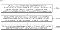
- the calculating an acceleration multiple based on the degree of degradation identified under the operating condition for accelerated degradation and under the normal operating condition may include calculating an accelerated-degradation speed under the operating condition for accelerated degradation, based on the identified degree of degradation under the operating condition for accelerated degradation, calculating a normal degradation speed under the normal operating condition, based on the identified degree of degradation under the normal operating condition, and calculating the acceleration multiple by dividing the accelerated-degradation speed by the normal degradation speed.
- the accelerated-degradation speed and the normal degradation speed may indicate a slope of a graph that is obtained by matching a voltage value on a time basis with the same electric current density as a reference after operating the fuel cell on a time basis under the normal operating condition and under the operating condition for accelerated degradation.
- the acceleration multiple may indicate how many more times the fuel cell is degraded when operated under the operating condition for accelerated degradation than when operated under the normal operating condition.
- the predicting the life of the membrane electrode assembly based on the acceleration multiple may include deriving the time it takes for performance of the fuel cell to be decreased by a predetermined percentage from initial performance when operating the fuel cell under the operating condition for accelerated degradation, and predicting the life of the membrane assembly by multiplying the derived time and the acceleration multiple.
- the method may further including deriving an optimal condition for an electric current that is to be applied to the fuel cell such that the fuel cell has optimal durability, based on the derived operating condition for accelerated degradation, which is applicable to the fuel cell.
- the deriving an optimal condition for an electric current that is to be applied to the fuel cell may include fixing the relative humidity conditions of the anode and the cathode of the fuel cell and the temperature condition of the fuel cell, among the derived operating conditions for accelerated degradation, operating the fuel cell by applying multiple different electric currents to the fuel cell, and identifying the degree of degradation of the fuel cell under a condition for each of the multiple electric currents, and selecting as an optimal condition for an electric current a condition for an electric current under which the degree of degradation of the fuel cell is lowest.
- the operating condition for accelerated degree of degradation which is applicable to the fuel cell, can be derived, and the life of the membrane electrode assembly of the fuel battery can be easily predicted using the derived operating condition for accelerated degradation.
- FIG. 1 is a diagram illustrating a flow for performing a method of predicting a life of a membrane electrode assembly of a fuel cell for electric power generation according to an exemplary embodiment of the present disclosure
- FIG. 2 is a flowchart illustrating steps of deriving an operating condition for accelerated degradation, which is applicable to the fuel cell for electric power generation, in the method of predicting the life of the membrane electrode assembly of the fuel cell for electric power generation according to an exemplary embodiment of the present disclosure
- FIG. 3 is a table illustrating operating conditions for deriving operating conditions for accelerated degradation, which are applicable to the fuel cell for electric power generation, in the method of predicting the life of the membrane electrode assembly of the fuel cell for electric power generation according to an exemplary embodiment of the present disclosure
- FIG. 4 is a diagram illustrating a result of analysis of a degree of degradation under each of the conditions in FIG. 3 ;
- FIG. 5 is a diagram illustrating durability that results from operating on a time basis under a normal operating condition and durability that results from operating on a time basis under the operating condition for accelerated degradation, in the method of predicting the life of the membrane electrode assembly of the fuel cell for electric power generation according to an exemplary embodiment of the present disclosure
- FIG. 6 is a diagram illustrating an accelerated-degradation speed under an accelerated operating condition and a degradation speed under the normal operating condition, in the method of predicting the life of the membrane electrode assembly of the fuel cell for electric power generation according to an exemplary embodiment of the present disclosure
- FIG. 7 is a diagram illustrating steps of calculating an acceleration multiple, in the method of predicting the life of the membrane electrode assembly of the fuel cell for electric power generation according to an exemplary embodiment of the present disclosure
- FIG. 8 is a diagram illustrating steps of predicting the life of the membrane electrode assembly based on the acceleration multiple, in the method of predicting the life of the membrane electrode assembly of the fuel cell for electric power generation according to an exemplary embodiment of the present disclosure.
- FIG. 9 is a diagram illustrating steps of determining the effectiveness of the derived operating condition for accelerated degradation, in the method of predicting the life of the membrane electrode assembly of the fuel cell for electric power generation according to an exemplary embodiment of the present disclosure.
- FIG. 1 is a diagram illustrating a flow for performing the method of predicting the life of the membrane electrode assembly of the fuel cell for electric power generation according to an exemplary embodiment of the present disclosure.
- FIG. 2 is a flowchart illustrating steps of deriving an operating condition for accelerated degradation, which is applicable to the fuel cell for electric power generation.
- FIG. 3 is a table illustrating operating conditions for deriving operating conditions for accelerated degradation, which are applicable to the fuel cell for electric power generation.
- FIG. 4 is a diagram illustrating a result of analysis of a degree of degradation under each of the conditions in FIG. 3 .
- FIG. 5 is a diagram illustrating durability that results from operating on a time basis under a normal operating condition and durability that results from operating on a time basis under the operating condition for accelerated degradation.
- FIG. 6 is a diagram illustrating an accelerated-degradation speed under an accelerated operating condition and a degradation speed under the normal operating condition.
- FIG. 7 is a diagram illustrating steps of calculating an acceleration multiple.
- FIG. 8 is a diagram illustrating steps of predicting the life of the membrane electrode assembly based on the acceleration multiple.
- FIG. 9 is a diagram illustrating steps of determining the effectiveness of the derived operating condition for accelerated degradation.
- a method of predicting a life of a membrane electrode assembly of a fuel cell for electric power generation includes Step S 100 of deriving an operating condition for accelerated degradation, which is applicable to the fuel cell, Step S 200 of operating the fuel cell for a specific time under the derived operating condition for accelerated degradation and under the normal operating condition and then identifying a degree of degradation of the fuel cell under each of the operating conditions, Step S 300 of calculating an acceleration multiple based on the degree of degradation identified under the derived operating condition for accelerated degradation and under the normal operating condition, and Step S 400 of predicting the life of the membrane electrode assembly based on the calculated acceleration multiple.
- Step S 100 of deriving an operating condition for accelerated degradation which is applicable to the fuel cell, as illustrated in FIG. 2 , includes Step S 110 of applying a specific electric current to the fuel cell, but of repeatedly operating the fuel cell at a specific time interval while changing relative-humidity conditions of an anode and a cathode of the fuel cell and a temperature condition of the fuel cell, and then of identifying the degree of degradation and a tendency for the degree of degradation under each of the conditions, Step S 120 of checking whether or not the identified degree of degradation under each of the conditions falls within a predetermined range of degrees of degradation and of comparing the tendency of the degree of degradation with a tendency for the degree of degradation, which is identified after operating the fuel cell under a normal operating condition, and Step S 130 of selecting a condition under which the degree of degradation falls within the predetermined range of the degrees of degradation and under which the tendency of the degree of degradation is the same as the tendency for the degree of degradation, which is identified under the normal operating condition, from among the identified degrees of degradation.
- the fuel cell is repeatedly operated at a specific time interval under six different conditions and then the degree of degradation and the tendency for the degree of degradation under each of the conditions are identified in FIG. 4 , in the step of applying a specific electric current to the fuel cell, but of repeatedly operating the fuel cell at a specific time interval while changing relative-humidity conditions of an anode and a cathode of the fuel cell and a temperature condition of the fuel cell, and then of identifying the degree of degradation and the tendency for the degree of degradation under each of the conditions.
- Steps of identifying the degree of degradation and the tendency for the degree of degradation under each of the conditions are described as follows with reference to FIGS. 3 and 4 .
- OCV open circuit voltage
- the operations 1-1 and 1-2 are performed repeatedly, and the degree of degradation and the tendency for the degree of degradation are identified at an interval of 100 hours through performance analysis.
- OCV open circuit voltage
- the operations 2-1 and 2-2 are performed repeatedly, and the degree of degradation and the tendency for the degree of degradation are identified at an interval of 100 hours through the performance analysis.
- OCV open circuit voltage
- the operations 3-1 and 3-2 are performed repeatedly, and the degree of degradation and the tendency for the degree of degradation are identified at an interval of 100 hours through the performance analysis.
- OCV open circuit voltage
- the operations 4-1 and 4-2 are performed repeatedly, and the degree of degradation and the tendency for the degree of degradation are identified at an interval of 100 hours through the performance analysis.
- the operations 5-1 and 5-2 are performed repeatedly, and the degree of degradation and the tendency for the degree of degradation are identified at an interval of 100 hours through the performance analysis.
- OCV open circuit voltage
- the operations 6-1 and 6-2 are performed repeatedly, and the degree of degradation and the tendency for the degree of degradation are identified at an interval of 100 hours through the performance analysis.
- a value of X in the electric current of X A/cm 2 that is applied to the fuel cell ranges 0 to 1.5.
- the fuel cell is operated, and then, as illustrated in FIG. 4 , the degree of degradation and the tendency for the degree of degradation under each of the conditions can be identified.
- the degree of degradation and the tendency of the degree of degradation indicate which one of components, such as a catalyst, a membrane, and a gas diffusion layer (GDL), that are included in the fuel cell is degraded much more.
- GDL gas diffusion layer
- the degree of degradation and the tendency of the degree of degradation can be identified based on at least one or more of an open circuit voltage (OCV) analysis, a voltage density analysis, an electric current density analysis, an Ohmic analysis, a crossover analysis, and an electrochemical surface area (ECSA) analysis.
- OCV open circuit voltage
- the OCV analysis identifies how much the membrane is damaged.
- the voltage density analysis and the electric current density analysis identify how much performance of all stacks of the fuel cell decrease.
- the Ohmic analysis identifies how much resistance of the stack of the fuel cell is increased.
- the crossover analysis identifies how much the membrane permits hydrogen to pass through.
- the ECSA analysis identifies how much an activation area of the catalyst is reduced.
- the degree of degradation of the fuel cell is identified with a result of each of these analyses.
- the degree of degradation and the tendency for the degree under Condition 1 to Condition 6 are identified as described above. Subsequently, it is checked whether or not the identified degree of degradation under each of the conditions falls within a predetermined range of degrees of degradation, and the tendency of the degree of degradation is compared with the tendency for the degree of degradation that is identified after operating the fuel cell. Thereafter, a condition under which the degree of degradation that is identified under Condition 1 to Condition 6 falls within the predetermined range of the degrees of degradation and under which the tendency of the degree of degradation is the same as the tendency for the degree of degradation, which is identified under the normal operating condition is selected as the operating condition for accelerated degradation, which is applicable to the fuel cell.
- the predetermined range of the degrees of degradation is a range of degrees of degradation in which performance of the stack of the fuel cell decreases by 5% to 20% of its initial performance with a voltage of the stack of the fuel cell as a reference.
- a point in time when the performance decreases by 20% of the initial performance with the voltage of the stack of the fuel cell as a reference means a point in time when the operating of a relevant fuel cell system has to be finished.
- a point in time when the performance decreases by 5% of the initial performance with the voltage of the stack of the fuel cell as a reference means an initial point in time when the degree of degradation of a constituent element within a relevant stack of the fuel cell can be identified.
- condition of Condition 1 to Condition 6 the performance decreases by 5% to 20% of the initial performance with the voltage of the stack of the fuel cell as a reference is identified, and under which condition the tendency for the degree of degradation is consistent with a condition for the tendency for the degree degradation, which is identified after operating the fuel cell under a normal condition, is identified.
- the resulting condition is selected as the operating condition for accelerated degradation, which is applicable to the fuel cell.
- Step S 200 of operating the fuel cell for a specific time under the derived operating condition for accelerated degradation and under the normal operating condition and then identifying a degree of degradation of the fuel cell under each of the operating conditions the fuel cell may be operated for a specific time under the operating condition for accelerated degradation, which is derived in Step S 100 , and under a normal operating condition, and then the degree of degradation of the fuel cell and the tendency for the degree of degradation thereof under each of the operating conditions can be identified as illustrated in FIG. 5 .
- FIG. 5 is a graph showing a voltage of the stack of the fuel cell under each of the operating conditions, with respect to an electric current density that results from operating the fuel cell for the specific time under the operating condition for accelerated degradation and the normal operating condition.
- a rate of decrease in performance that is, the degree of degradation and the tendency for the degree of degradation, under each of the operating conditions, can be identified through a rate of decrease in the voltage of the stack of the fuel cell.
- Step S 300 of calculating an acceleration multiple based on the degree of degradation that is identified under the operating condition for accelerated degradation and under the normal operating condition in Step S 200 may include Step S 310 of calculating the accelerated-degradation speed under the operating condition for accelerated degradation, based on the identified degree of degradation under the operating condition for accelerated degradation, Step S 320 of calculating a normal degradation speed under the normal operating condition, based on the degree of degradation under the derived normal operating condition, and Step S 330 of calculating the acceleration multiple by dividing the accelerated-degradation speed by the normal degradation speed.
- a graph as in FIG. 6 is obtained by matching a voltage value on a time basis on the graph in FIG. 5 with the same electric current density as a reference.
- a slope of Graph A means the normal degradation speed
- a slope of Graph B is the accelerated-degradation speed.
- the accelerated-degradation speed and the normal degradation speed are calculated, and then the acceleration multiple is calculated by dividing the accelerated-degradation speed by the normal degradation speed.
- the acceleration multiple indicates how many more times the fuel cell is degraded when operated under the operating condition for accelerated degradation than when operated under the normal operating condition.
- Step S 400 of predicting the life of the membrane electrode assembly based on the acceleration multiple may include Step S 410 of deriving the time it takes for performance of the fuel cell to decrease by a predetermined percentage of its initial performance when operating the fuel cell under the operating condition for accelerated degradation, and Step S 420 of predicting the life of the membrane electrode assembly by multiplying the derived time and the acceleration multiple.
- a life expectancy of the membrane electrode assembly of the fuel cell is 20,000 hours, which results from multiplying 1,000 hours by 20.
- a point in time when the fuel cell decreases by 20% of its initial performance means a point in time when the operating of the fuel cell has to be finished.
- the method of predicting a life of a membrane electrode assembly of a fuel cell may further include Step S 500 of deriving an optimal condition for an electric current that is to be applied to the fuel cell such that the fuel cell has optimal durability, with the derived operating condition for accelerated degradation, which is applicable to the fuel cell, as a reference, subsequently to the step of deriving the operating condition for accelerated degradation, which is applicable to the fuel cell.
- the step of deriving the optimal condition for the electric current that is to be applied to the fuel cell may include Step S 510 of fixing relative humidity conditions of the anode and the cathode of the fuel cell, and a temperature condition of the fuel cell, among the derived operating conditions for accelerated degradation, then of applying multiple different electric currents to the fuel cell, of operating the fuel cell, and of identifying the degree of degradation of the fuel cell under a condition for each of the multiple electric currents, and Step S 520 of selecting as an optimal condition for an electric current a condition for an electric current under which the degree of degradation of the fuel cell is lowest.
- the relative humidity conditions of the anode and the cathode of the fuel cell and the temperature condition of the fuel cell, among the derived operating conditions for accelerated degradation are fixed. Thereafter, different electric currents, that is, an electric current of 0.2 A/cm 2 , an electric current of 0.5 A/cm 2 , and an electric current of 1.0 A/cm 2 are applied to the fuel cell, the fuel cell is operated, the degree of degradation of the fuel cell and the tendency for the degree of degradation thereof under a condition for each of the electric currents are identified, and a condition under which the degree of degradation is lowest is selected as an optimal condition for an electric current.
- different electric currents that is, an electric current of 0.2 A/cm 2 , an electric current of 0.5 A/cm 2 , and an electric current of 1.0 A/cm 2 are applied to the fuel cell, the fuel cell is operated, the degree of degradation of the fuel cell and the tendency for the degree of degradation thereof under a condition for each of the electric currents are identified, and a condition under which
- the above described steps for the method of predicting a life of an MEA of a fuel cell for electric power generation may be performed by a processor (e.g., computer, microprocessor, CPU, ASIC, circuitry, logic circuits, etc.) having an associated non-transitory memory storing software instructions for the processor.
- a processor e.g., computer, microprocessor, CPU, ASIC, circuitry, logic circuits, etc.
Landscapes
- Engineering & Computer Science (AREA)
- Manufacturing & Machinery (AREA)
- Sustainable Development (AREA)
- Sustainable Energy (AREA)
- Chemical & Material Sciences (AREA)
- Chemical Kinetics & Catalysis (AREA)
- Electrochemistry (AREA)
- General Chemical & Material Sciences (AREA)
- Life Sciences & Earth Sciences (AREA)
- Physics & Mathematics (AREA)
- General Physics & Mathematics (AREA)
- Artificial Intelligence (AREA)
- Computing Systems (AREA)
- Evolutionary Computation (AREA)
- Fuzzy Systems (AREA)
- Medical Informatics (AREA)
- Software Systems (AREA)
- Theoretical Computer Science (AREA)
- Automation & Control Theory (AREA)
- Health & Medical Sciences (AREA)
- Fuel Cell (AREA)
Abstract
Description
Claims (10)
Applications Claiming Priority (2)
| Application Number | Priority Date | Filing Date | Title |
|---|---|---|---|
| KR10-2019-0083283 | 2019-07-10 | ||
| KR1020190083283A KR102916830B1 (en) | 2019-07-10 | 2019-07-10 | Method for predicting life cycle of membrane electrode assembly of fuel cel for power generation |
Publications (2)
| Publication Number | Publication Date |
|---|---|
| US20210013530A1 US20210013530A1 (en) | 2021-01-14 |
| US11309560B2 true US11309560B2 (en) | 2022-04-19 |
Family
ID=74058523
Family Applications (1)
| Application Number | Title | Priority Date | Filing Date |
|---|---|---|---|
| US16/824,898 Active 2040-12-10 US11309560B2 (en) | 2019-07-10 | 2020-03-20 | Method of predicting life of membrane electrode assembly of fuel cell for electric power generation |
Country Status (4)
| Country | Link |
|---|---|
| US (1) | US11309560B2 (en) |
| KR (1) | KR102916830B1 (en) |
| CN (1) | CN112216851B (en) |
| DE (1) | DE102020112820A1 (en) |
Families Citing this family (5)
| Publication number | Priority date | Publication date | Assignee | Title |
|---|---|---|---|---|
| KR102660502B1 (en) * | 2019-04-18 | 2024-04-24 | 현대모비스 주식회사 | Method for managing battery for vehicle and apparatus for the same |
| CN115411306B (en) * | 2022-08-11 | 2025-04-04 | 华中科技大学 | A method for quantifying the health status of proton exchange membrane fuel cells |
| CN116914198B (en) * | 2023-06-21 | 2024-08-30 | 中国石油大学(华东) | Accelerated test method for durability of solid oxide fuel cell stack |
| KR20250097531A (en) * | 2023-12-21 | 2025-06-30 | 한양대학교 산학협력단 | Apparatus and method for life prediction of fuel cell |
| KR102914573B1 (en) * | 2025-07-04 | 2026-01-16 | 한국건설기계연구원 | Durability test method of fuel cell for construction equipment |
Citations (2)
| Publication number | Priority date | Publication date | Assignee | Title |
|---|---|---|---|---|
| KR100647675B1 (en) | 2005-01-21 | 2006-11-23 | 삼성에스디아이 주식회사 | Accelerated test method for fuel cell life assessment |
| US20180292464A1 (en) * | 2017-04-06 | 2018-10-11 | Toyota Jidosha Kabushiki Kaisha | Inspection apparatus and inspection method for membrane electrode assembly |
Family Cites Families (15)
| Publication number | Priority date | Publication date | Assignee | Title |
|---|---|---|---|---|
| EP1542302B1 (en) * | 2003-11-18 | 2012-05-23 | Panasonic Corporation | Fuel cell life predicting device and fuel cell system |
| JP4953219B2 (en) * | 2003-11-18 | 2012-06-13 | パナソニック株式会社 | Fuel cell life prediction apparatus and fuel cell system |
| JP2007194026A (en) * | 2006-01-18 | 2007-08-02 | Mitsubishi Electric Corp | Membrane electrode assembly deterioration evaluation method and membrane electrode assembly deterioration evaluation apparatus |
| JP5111783B2 (en) * | 2006-05-15 | 2013-01-09 | 東芝燃料電池システム株式会社 | Polymer film lifetime prediction test method, test apparatus, and test program |
| CN102315461A (en) * | 2006-09-13 | 2012-01-11 | 日立麦克赛尔能源株式会社 | Membrane-electrode assembly and polymer electrolyte fuel cell |
| JP2008282644A (en) * | 2007-05-10 | 2008-11-20 | Toyota Motor Corp | Degradation assessment of membrane electrode assemblies used in fuel cells |
| KR101567079B1 (en) * | 2009-06-12 | 2015-11-09 | 현대자동차주식회사 | Method for testing electrolyte membrane endurance of fuel cell |
| JP2011100641A (en) * | 2009-11-06 | 2011-05-19 | Toyota Motor Corp | Method and device for evaluating membrane electrode assembly |
| JP5504932B2 (en) * | 2010-02-03 | 2014-05-28 | トヨタ自動車株式会社 | Method for predicting mechanical deterioration of solid polymer electrolyte membrane used in fuel cell, and deterioration prediction apparatus |
| US20130004872A1 (en) * | 2011-07-01 | 2013-01-03 | GM Global Technology Operations LLC | Method for early detection of membrane failures of fuel cell stacks and fuel cell system component defects |
| JP5734780B2 (en) * | 2011-07-26 | 2015-06-17 | 株式会社東芝 | Life prediction method of electrolyte membrane in polymer electrolyte fuel cell |
| JP2014038705A (en) * | 2012-08-10 | 2014-02-27 | Toyota Motor Corp | Fuel cell stack, fuel cell system, and fuel cell stack manufacturing method |
| JP5858023B2 (en) * | 2013-10-25 | 2016-02-10 | トヨタ自動車株式会社 | Durability inspection device and durability inspection method for membrane electrode assembly |
| KR101776390B1 (en) * | 2015-07-29 | 2017-09-08 | 현대자동차주식회사 | Method and system for diagnosis of fuel cell, and method for controling the fuel cell using the same |
| KR101665572B1 (en) * | 2015-12-21 | 2016-10-24 | 한국에너지기술연구원 | Method of operating high-temperature polymer electrolyte memberance fuel cell for maximizing stack life of thereof |
-
2019
- 2019-07-10 KR KR1020190083283A patent/KR102916830B1/en active Active
-
2020
- 2020-03-20 US US16/824,898 patent/US11309560B2/en active Active
- 2020-04-13 CN CN202010284709.4A patent/CN112216851B/en active Active
- 2020-05-12 DE DE102020112820.7A patent/DE102020112820A1/en active Pending
Patent Citations (2)
| Publication number | Priority date | Publication date | Assignee | Title |
|---|---|---|---|---|
| KR100647675B1 (en) | 2005-01-21 | 2006-11-23 | 삼성에스디아이 주식회사 | Accelerated test method for fuel cell life assessment |
| US20180292464A1 (en) * | 2017-04-06 | 2018-10-11 | Toyota Jidosha Kabushiki Kaisha | Inspection apparatus and inspection method for membrane electrode assembly |
Also Published As
| Publication number | Publication date |
|---|---|
| CN112216851A (en) | 2021-01-12 |
| CN112216851B (en) | 2025-07-15 |
| KR20210008198A (en) | 2021-01-21 |
| KR102916830B1 (en) | 2026-01-23 |
| US20210013530A1 (en) | 2021-01-14 |
| DE102020112820A1 (en) | 2021-01-14 |
Similar Documents
| Publication | Publication Date | Title |
|---|---|---|
| US11309560B2 (en) | Method of predicting life of membrane electrode assembly of fuel cell for electric power generation | |
| Mittermeier et al. | PEM fuel cell start-up/shut-down losses vs temperature for non-graphitized and graphitized cathode carbon supports | |
| Hu et al. | Comprehensive analysis of galvanostatic charge method for fuel cell degradation diagnosis | |
| US11018358B2 (en) | Pinhole determination method and system for fuel cell | |
| US10534040B2 (en) | Inspection apparatus and inspection method for membrane electrode assembly | |
| Bae et al. | Degradation pattern prediction of a polymer electrolyte membrane fuel cell stack with series reliability structure via durability data of single cells | |
| Phillips et al. | Utilizing a segmented fuel cell to study the effects of electrode coating irregularities on PEM fuel cell initial performance | |
| US10622652B2 (en) | Fuel cell system and control method therefor | |
| US10892502B2 (en) | Apparatus and method for controlling operation of fuel cell system | |
| CN101515024A (en) | Online low performing cell prediction and detection of fuel cell system | |
| Hashimasa et al. | Comparison of carbon corrosion test methods for polymer electrolyte fuel cell | |
| US20150165928A1 (en) | Technique of diagnosing fuel cell stack | |
| US9929419B2 (en) | Device and method for monitoring dryness of fuel cell stack | |
| CN115935659A (en) | Fuel cell stack service life prediction method and system and electronic equipment | |
| US10340541B2 (en) | Operation control method and system of fuel cell | |
| US10840526B2 (en) | Method and apparatus for evaluating movement tendency of ions in electrolyte membrane | |
| CN112238761B (en) | Fuel cell system and method of controlling the same | |
| JP2002298890A (en) | Defective cell detection method for fuel cell | |
| Lübben et al. | Test procedure for the prediction of water transport in polymer electrolyte fuel cells | |
| US20240304841A1 (en) | Electrochemical cell degradation monitoring method and system | |
| JP2021111438A (en) | Method for estimating degree of deterioration of fuel cell stack having multiple stacked fuel cells | |
| US20240347744A1 (en) | Fuel cell system for performance recovery and operation method thereof | |
| Breitinger et al. | Automotive Fuel Cell Systems: Testing Highly Dynamic Scenarios. Energies 2023, 16, 664 | |
| JP4325231B2 (en) | Fuel cell output characteristic estimation apparatus and output characteristic estimation method | |
| Sugawara et al. | Electrocatalytic activity analysis of PEFC cathode by 1-D macrohomogeneous model of catalyst layer |
Legal Events
| Date | Code | Title | Description |
|---|---|---|---|
| FEPP | Fee payment procedure |
Free format text: ENTITY STATUS SET TO UNDISCOUNTED (ORIGINAL EVENT CODE: BIG.); ENTITY STATUS OF PATENT OWNER: LARGE ENTITY |
|
| AS | Assignment |
Owner name: KIA MOTORS CORPORATION, KOREA, REPUBLIC OF Free format text: ASSIGNMENT OF ASSIGNORS INTEREST;ASSIGNORS:DONG, HYUN BAE;CHO, MIN KYUNG;KIM, WON JUNG;AND OTHERS;SIGNING DATES FROM 20191224 TO 20200107;REEL/FRAME:052189/0660 Owner name: KOREA INSTITUTE OF SCIENCE AND TECHNOLOGY, KOREA, REPUBLIC OF Free format text: ASSIGNMENT OF ASSIGNORS INTEREST;ASSIGNORS:DONG, HYUN BAE;CHO, MIN KYUNG;KIM, WON JUNG;AND OTHERS;SIGNING DATES FROM 20191224 TO 20200107;REEL/FRAME:052189/0660 Owner name: HYUNDAI MOTOR COMPANY, KOREA, REPUBLIC OF Free format text: ASSIGNMENT OF ASSIGNORS INTEREST;ASSIGNORS:DONG, HYUN BAE;CHO, MIN KYUNG;KIM, WON JUNG;AND OTHERS;SIGNING DATES FROM 20191224 TO 20200107;REEL/FRAME:052189/0660 |
|
| STPP | Information on status: patent application and granting procedure in general |
Free format text: DOCKETED NEW CASE - READY FOR EXAMINATION |
|
| AS | Assignment |
Owner name: HYUNDAI MOTOR COMPANY, KOREA, REPUBLIC OF Free format text: ASSIGNMENT OF ASSIGNORS INTEREST;ASSIGNORS:HYUNDAI MOTOR COMPANY;KIA MOTORS CORPORATION;KOREA INSTITUTE OF SCIENCE AND TECHNOLOGY;REEL/FRAME:052565/0852 Effective date: 20200413 Owner name: KIA MOTORS CORPORATION, KOREA, REPUBLIC OF Free format text: ASSIGNMENT OF ASSIGNORS INTEREST;ASSIGNORS:HYUNDAI MOTOR COMPANY;KIA MOTORS CORPORATION;KOREA INSTITUTE OF SCIENCE AND TECHNOLOGY;REEL/FRAME:052565/0852 Effective date: 20200413 Owner name: KOREA INSTITUTE OF SCIENCE AND TECHNOLOGY, KOREA, REPUBLIC OF Free format text: ASSIGNMENT OF ASSIGNORS INTEREST;ASSIGNORS:HYUNDAI MOTOR COMPANY;KIA MOTORS CORPORATION;KOREA INSTITUTE OF SCIENCE AND TECHNOLOGY;REEL/FRAME:052565/0852 Effective date: 20200413 |
|
| STPP | Information on status: patent application and granting procedure in general |
Free format text: NOTICE OF ALLOWANCE MAILED -- APPLICATION RECEIVED IN OFFICE OF PUBLICATIONS |
|
| STPP | Information on status: patent application and granting procedure in general |
Free format text: PUBLICATIONS -- ISSUE FEE PAYMENT VERIFIED |
|
| STCF | Information on status: patent grant |
Free format text: PATENTED CASE |
|
| MAFP | Maintenance fee payment |
Free format text: PAYMENT OF MAINTENANCE FEE, 4TH YEAR, LARGE ENTITY (ORIGINAL EVENT CODE: M1551); ENTITY STATUS OF PATENT OWNER: LARGE ENTITY Year of fee payment: 4 |